EP3296465A1 - Parkplatzschrankenvorrichtung - Google Patents
Parkplatzschrankenvorrichtung Download PDFInfo
- Publication number
- EP3296465A1 EP3296465A1 EP17188138.6A EP17188138A EP3296465A1 EP 3296465 A1 EP3296465 A1 EP 3296465A1 EP 17188138 A EP17188138 A EP 17188138A EP 3296465 A1 EP3296465 A1 EP 3296465A1
- Authority
- EP
- European Patent Office
- Prior art keywords
- base
- bases
- parking
- hoop
- openings
- Prior art date
- Legal status (The legal status is an assumption and is not a legal conclusion. Google has not performed a legal analysis and makes no representation as to the accuracy of the status listed.)
- Granted
Links
Images



Classifications
-
- E—FIXED CONSTRUCTIONS
- E01—CONSTRUCTION OF ROADS, RAILWAYS, OR BRIDGES
- E01F—ADDITIONAL WORK, SUCH AS EQUIPPING ROADS OR THE CONSTRUCTION OF PLATFORMS, HELICOPTER LANDING STAGES, SIGNS, SNOW FENCES, OR THE LIKE
- E01F13/00—Arrangements for obstructing or restricting traffic, e.g. gates, barricades ; Preventing passage of vehicles of selected category or dimensions
- E01F13/04—Arrangements for obstructing or restricting traffic, e.g. gates, barricades ; Preventing passage of vehicles of selected category or dimensions movable to allow or prevent passage
- E01F13/08—Arrangements for obstructing or restricting traffic, e.g. gates, barricades ; Preventing passage of vehicles of selected category or dimensions movable to allow or prevent passage by swinging into closed position about a transverse axis situated in the road surface, e.g. tiltable sections of the road surface, tiltable parking posts
- E01F13/085—Arrangements for obstructing or restricting traffic, e.g. gates, barricades ; Preventing passage of vehicles of selected category or dimensions movable to allow or prevent passage by swinging into closed position about a transverse axis situated in the road surface, e.g. tiltable sections of the road surface, tiltable parking posts specially adapted for individual parking spaces
Definitions
- the invention relates to a parking barrier device intended to be anchored to the ground.
- the invention further relates to equipment comprising a parking barrier device according to the invention and nails for traversing openings of a base system of the barrier device.
- the invention also relates to a method of laying such equipment on an asphalt floor.
- Asphalt means asphalt mixes that are a mixture of gravel, sand and hydrocarbon binder to form the pavement.
- the invention also relates to a parking area having an asphalt floor comprising an equipment according to the invention, the parking barrier device of which is fixed to the ground by means of the nails passing through the openings of the base system, the nails inserted directly into the floor system. through the asphalt layer of the soil.
- the field of the invention is that of parking barriers which are fixed to the ground and positioned in a vehicle parking place, outside or inside, to prevent vehicles from parking on said location.
- the holder of the parking barrier can thus prevent vehicles, other than those authorized, from parking on the parking space belonging to the holder of the barrier.
- the parking barriers known from the state of the art conventionally comprise a hoop whose two ends are respectively pivotally connected to two bases. This hoop is adapted to rotate around the bases of a lowered position, allowing the parking of a vehicle above the barrier, to a raised position, prohibiting parking.
- the barrier device conventionally has a locking mechanism of the hoop in the raised position and which comprises a slider system having two tubes slidably mounted relative to each other.
- Said slide system has an end secured to one of the tubes and pivotally connected to the bow, and another end secured to the other tube and pivotally connected to a third base.
- This system slider moves from an extended position in said lowered position of the hoop to a retracted position in said raised position of the hoop.
- Said locking mechanism further comprises a locking system, for example a key lock mechanism, which ensures the blocking of the sliding between the two tubes in said retracted position of the slider system and so as to lock the hoop.
- the barrier manufacturers recommend to fix such parking barrier devices on the ground on a slab or blocks of concrete to obtain optimal fixation with screws.
- car parks are asphalt.
- the fixing of the barrier requires previously to break down the layer of asphalt and disburden the lower layer to create cavities of sufficient size to pour concrete pads which is long and expensive.
- asphalt parking places bear the stigma of such operations with the presence on the asphalt layer of many particularly unsightly concrete blocks.
- parking barriers comprising a hoop in pivot connection with bases and a slider system pivotally connected to the hoop of one end and pivotally connected to a base of the other end.
- the bases in pivot connection with the ends of the hoop and that of the slider system are independent (that is to say not connected to each other by a common base) as is the case for the reference model B307C of at MOTTEZ for example.
- Said three independent bases are screwed on the ground which must be slab or concrete to allow good resistance to tearing.
- the aforementioned parking barriers are difficult to install in that they require to identify precisely the three anchor points on the ground for these three bases. For example, if the measurements between the bases of the ends of the rollbar and the slider system are false or poorly reported on the ground, the parking barrier will be incorrectly installed and the floor will have more deterioration than necessary due to measurement errors. .
- the ground is asphalt, it is necessary to break the asphalt slab to manufacture concrete pads to fix said three bases on the ground.
- each base and said base are constituted by an integral element, obtained from cutting operation and folding a sheet. More specifically, each base is obtained by two cuts of the sheet forming the base, semi-circular, then the folding of the cut parts, along a diametrical folding line and substantially perpendicular to the base. These cutting and folding operations make it possible to form each base, substantially each constituted by two flanges of the projecting plate perpendicular to the horizontal wall of the base. These two wings are connected by a pivot axis about which pivots the corresponding end of the arch (or the slide system).
- such a barrier device simplifies laying operations thanks to the presence of the common base, but does not give full satisfaction in terms of tearing resistance performance, and compared to the barrier device with three independent bases.
- the inventor has found that the method of manufacturing such a barrier whose bases and base are constituted by the same sheet (after cutting and folding operations) requires the presence of large openings in the base, two in number, adjacent to each base, laterally: more and according to the findings of the inventor these large openings prevent the installation of fasteners through the base in the immediate vicinity of the bases, where these organs of fasteners provide better performance in terms of tear resistance.
- the tearing performance of such a barrier whose bases have a common base drops sharply in the case of laying on a floor with irregularities of level, and compared to the performance obtained by barriers to three independent bases that can be fixed independently to the ground at three anchoring zones, adapting to the irregularities of the soil in these three zones.
- the purpose of the present invention is to overcome the aforementioned drawbacks of existing parking barriers by providing a barrier device simplifying installation, while providing good performance in terms of resistance to tearing.
- Another aim is to propose, at least according to one embodiment, such a barrier device simplifying the laying and having good tearing resistance performance, even in the case of a laying on a floor with differences in strength. level.
- Another object of the present invention is to provide equipment comprising a barrier device and fasteners allowing anchoring of the barrier on an asphalt floor, advantageously without requiring the production of concrete pads.
- Another aim is to propose a method of laying such equipment, or a method of laying such a barrier device.
- the invention relates to a parking barrier device easy to use, resistant to tearing and which is positioned in a vehicle parking space, outside or inside, to prevent vehicles from parking on said location.
- the holder of said parking barrier device can thus prevent vehicles other than that of the holder of said parking device. parking barrier, parking on said location belonging to the holder of said parking barrier device.
- said base system comprises openings near the bases for fasteners for connecting said base system to the ground.
- these openings of the base system allow the positioning of fasteners near the bases, namely in the optimum positions where the fasteners provide the best performance in terms of resistance to tearing.
- said base system having two section reductions of the sheet, respectively between one of the bases of the arch and the base of the slide system, on the one hand, and between said base the slider system and the other base of said hoop, on the other hand, each section reductions being determined, locally in the direction of the sheet substantially radial to the arc.
- these two section reductions form two flexible connections between the three bases and their respective openings for the fasteners; such flexible connections make it possible to adapt the sheet to a non-planar surface, by plating it on the ground, allowing a more intimate contact between the plate of the base system and the non-flat surface of the base: good performances are maintained in terms of resistance to tearing even in the case of installation of the barrier device on a non-planar surface, having differences in level.
- the invention further relates to equipment comprising a parking barrier device according to the invention and nails for traversing said openings of said base system, the nail heads being of greater diameter audites openings.
- Such equipment finds particular application for barrier installation on asphalt floors, advantageously without requiring the realization of concrete pad.
- the invention relates to a method of laying said equipment according to the invention on an asphalt floor in which said base system is nailed to the ground by direct insertion of the nails through the asphalt layer.
- the invention also relates to a parking area having an asphalt floor comprising an equipment according to the invention, the parking barrier device is fixed to the ground by means of the nails through the openings of the base system, the nails inserted directly into the floor. through the asphalt layer of the soil.
- the barrier device according to the invention will also find a particular application in indoor car parks for which it is often forbidden to pierce the ground; in such a case the lower surface of the base system advantageously allow anchoring by gluing; also the invention also relates to a method of laying a device according to the invention, wherein said base system (in particular the pre-cut sheet) is glued to the ground.
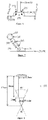
- the invention relates to a parking barrier device 1, illustrated according to a non-limiting example on the Figures 1, 2 , 3, 4 , 5 , 9 and 10 .
- This parking barrier device comprises a hoop 2, whose two ends are pivotally connected to two bases 4, the hoop 2 being able to go through rotation of a lowered position visible on the figure 2 , allowing the parking of a vehicle above the barrier, to a raised position visible on the figure 1 , prohibiting parking.
- the arch 2 can be obtained from a rigid metal tube after bending operations of the tube.
- the hoop may have a section of rectilinear intermediate length, intended to be parallel to the ground, and sections of substantially perpendicular end length each connected to the intermediate section by a bend of the tube.
- the pivot connections between the two bases and the ends of the hoop 2 are obtained by rotation of the ends of the hoop 2 about axes, parallel to the ground carried by the bases.
- Said pivot connections between the ends of the hoop 2 and the bases 4 allow the rotation of the hoop 2 which can pass from a visible down position on the figure 2 , allowing the parking of a vehicle above the parking barrier device 1, to a raised position visible on the figure 1 , prohibiting parking.
- the parking barrier device 1 also comprises a locking mechanism of the hoop 2 in the raised position visible on the figures 1 , 3-5 , 9 and 10 .
- Said locking mechanism of the hoop 2 comprises a slider system 3, and a locking system 6 adapted to block the slider system in said raised position of the hoop 2.
- the slider system is able to pass from a position deployed in said lowered position of the hoop 2 to a retracted position in said raised position of the hoop 2.
- Said locking system 6 may be a key lock for example.
- Said slide system 3 is visible on the figure 7 and comprises two tubes 32 and 33, an inside 33 and an outside 32, slidably mounted relative to each other.
- One end of said outer tube 32 or, conversely, inner tube 33 is pivotally connected to the hoop 2, in particular at the intermediate section, and one end of said inner tube 33, or vice versa, 32 is pivotally connected to a third base plate of the slide system 5.
- the free ends of said inner tubes 33 and outer 32 of said slider system 3 may have stops 34, obtained for example with an outwardly projecting return for the inner tube 33 and an inner return for the tube outer 32, preventing said outer tube 32 and inner 33 to separate.
- Said inner 33 and outer 32 tubes are obtained from rigid material such as metal.
- the pivot connection between the hoop 2 and the slider system 3 can be obtained from a tube 31 rigidly secured to the end of the outer tube (or inner) through which the intermediate length section of the hoop 2. This attachment is non-limiting and can be done by welding, for example.
- the parking barrier device 1 comprises a pedestal system 7 interconnecting the two bases of the arch 4 and the third base of the slider system 5.
- the base system comprises openings 71 near the bases for fasteners 72 intended to connect said base system 7 to the ground as is visible on the figures 1 and 3 .
- Said openings 71 of the base system 7, allow the passage of the fasteners 72 as is visible on the Figures 4 and 5 .
- the installation of the parking barrier device 1 is simplified.
- the base system is in itself a template that positions the openings 71 for the fasteners in the positions required for proper assembly.
- said openings 71 of the base system 7, allowing the passage of the fasteners, are distributed around said three bases 4 and 5, near the bases.
- these openings 71 arranged according to a fixing area 74 between 15 mm and 35 mm from the edge closest to the corresponding base as is visible on the figure 3 .
- the locations of said openings 71 are then positioned near the bases of the arch 4 and the slider system 5 and so as to provide good resistance to tearing.
- said base system 7 has, for each base of the arch 4 and the slider system 5, at least three openings 71 for fasteners 72.
- the openings 71 are for example three in number. or four for each base 4 or 5.
- the openings are three in number, allowing the respective insertion of three fasteners.
- Said openings 71 may be equidistant around the bases of the arch 4 and the slide system 5. Two of said openings 71 may be symmetrical with respect to the major axis of the bases of the arch 4 and of the slide system 5, namely in the direction of each of the bases perpendicular to the pivot connection, and the last of said openings 71 may be located on the major axis of said bases 4 and 5, between said bases 4 and 5 and the outer edge of the base system 7 as this is visible on the figure 3 . Such locations of said openings 71 allow a good attachment of the base system 7 with the ground through the fasteners 72 and thus a good resistance to tearing.
- the bases of the arch 4 and the slide system 5 can be distinct elements of the base system 7, assembled to said base system 7.
- the bases 4 or 5 may be plastic or metal elements secured to said base system by any suitable means such as screws with nuts, rivets, staples.
- the bases can still be secured to said base system by gluing or welding.
- the figures illustrate for example plastic bases, typically obtained by injection molding and which are secured to the base system by bolts, through corresponding openings between each base and the base system.
- said base system 7 may be a pre-cut sheet on which are fixed the three bases 4 and 5 in three distinct positions of attachment to the upper surface of the sheet, the openings 71 for the fasteners 72 intended for to connect said base system 7 to the ground being materialized by cuts of said sheet distributed near the bases.
- the thickness of the sheet 70 may be between 2mm and 5mm, for example 3mm.
- the sheet 70 may present locally, drawings 75 stiffening at the bases of the arch 4 and the slider system 5. These stampings are visible on the figure 6 and allow to increase the rigidity of the sheet at the bases, near the openings 71 for the fasteners. These stampings thus improve the tear resistance of the barrier and in comparison to a sheet that would be lacking.
- each stamping 75 locally deforms the protruding plate towards the corresponding base: each stamping forms a cavity on the underside of the sheet 70 which makes it possible to house one end of the fasteners connecting each base to the sheet, such as by example the head of a screw, or a nut. This prevents the member (screw head and / or nut) against the ground when the underside of the sheet is resting on the ground.
- the pre-cut sheet may have a general shape in an arc.
- the two bases of the hoop 4 are integral with the sheet at the ends of the arc and the third base of the slider system 5 is integral with the sheet at an intermediate portion of the arc, preferably at equal distance of the bases 4 of the arch.
- the sheet 70 may locally have two section reductions 72 of the sheet, respectively between one of the bases 4 of the arch and the base 5 of the slide system, on the one hand, and between said base 5 of the slider system and the other base 4 of said hoop on the other hand.
- Each section reduction is determined in the radial arc direction.
- Said reductions 73 of the base system 7 may be approximately 50% relative to the width of the sheet at said bases 4 and 5 and for example between 20% and 70%. Said reductions 73 make it possible to confer flexibility on the base system 7 between the bases 4 and 5, which overcomes the ground defects in the transverse axis as well as in the longitudinal axis, as can be seen in FIGS. Figures 9 and 10 : optimal contact is obtained between the floor and the base system 7 in order to obtain a good resistance to tearing.
- the invention also relates to equipment comprising a parking barrier device 1 and nails 9 intended to pass through the openings 71 of said base system 7.
- the nails 9 may have, from the head of the nail, a dimension in length between 70 mm and 150 mm, preferably between 90 mm and 120 mm and a diameter dimension of between 5 mm and 15 mm, preferably between 8 mm and 12 mm.
- the nail can thus have, from the nail head, a section of substantially cylindrical useful length of constant diameter, terminated by the tip of the nail.
- said nails may each have a diameter reduction at the point of the nail on a minor portion of the length of the nail, for example about one-sixth of their length.
- the nail can thus present, from the nail head, a first section of substantially cylindrical useful length of constant diameter, followed by a second section of useful length of the nail of reduced diameter, terminated by the tip of the nail.
- the nails can admit a length of 120mm of which, starting from the head of the nail, 90mm of this length admits a diameter of 12mm which is followed by a reduction of diameter being done progressively on approximately 1mm to obtain a diameter of 11mm on 15mm in length and which ends on a point whose angle is substantially equal to 40 degrees.
- Such an arrangement makes it possible to drive the tip of the nail, then the section of reduced diameter length, at least effort, and to ensure the correct position of the nail, substantially vertical to the ground. Depression of the larger diameter section of the nail can then be achieved by limiting the risk of biasing the nail.
- Such nails advantageously allow the fixing of the barrier device on an asphalt floor, without requiring the production of concrete pads.
- the shape of the nail allows to drive the nail with the help, for example, of a hammer.
- Nails in particular whose dimensions have been previously defined can be inserted using a hammer into an asphalt layer without pre-drilling.
- pre-drilling can be done with a 5mm diameter bit.
- the invention relates to a method of laying said equipment on an asphalt floor in which said base system 7 is grounded by inserting nails through the asphalt layer.
- the nails are inserted into the openings of the base 71, and driven hammer until the head of the nail abuts with said base system, in particular with the upper surface of the sheet.
- the invention also relates to a parking area having an asphalt floor comprising an equipment according to the invention, the parking barrier device is fixed to the ground by means of the nails through the openings of the base system, the nails inserted directly into the floor. through the asphalt layer of the soil.
- the barrier device according to the invention also finds particular application in indoor car parks for which it is often forbidden to pierce the ground; in such a case the lower surface of the base system advantageously allows anchoring by gluing; also the invention also relates to a method of laying a device according to the invention, wherein said base system (in particular the pre-cut sheet) is glued to the ground.
- Said methods for laying said equipment of said parking barrier device 1 and the use of the bases 4 and 5 for securing the ends of the hoop 2 and the slider system 3 with said base system 7 make it possible to obtain an aesthetic device , easy to install and with a good resistance to tearing up to 1200 kg under the conditions described in the tear test of the parking barrier device that follows.
- the inventor measured, using a load cell, the resistance of the barrier subjected to a tensile force.
- the pulling force is, initially, low to test the mounting of the tear test, the traction force then increases until the tear off of the parking barrier device.
- the tear off of the parking barrier device was carried out between the base system and the bases for a load of 1202kg.
Landscapes
- Engineering & Computer Science (AREA)
- Architecture (AREA)
- Civil Engineering (AREA)
- Structural Engineering (AREA)
- Refuge Islands, Traffic Blockers, Or Guard Fence (AREA)
- Road Paving Structures (AREA)
Applications Claiming Priority (1)
| Application Number | Priority Date | Filing Date | Title |
|---|---|---|---|
| FR1658592A FR3055909B1 (fr) | 2016-09-14 | 2016-09-14 | Dispositif de barriere de parking |
Publications (2)
| Publication Number | Publication Date |
|---|---|
| EP3296465A1 true EP3296465A1 (de) | 2018-03-21 |
| EP3296465B1 EP3296465B1 (de) | 2019-05-01 |
Family
ID=57906700
Family Applications (1)
| Application Number | Title | Priority Date | Filing Date |
|---|---|---|---|
| EP17188138.6A Active EP3296465B1 (de) | 2016-09-14 | 2017-08-28 | Parkplatzschrankenvorrichtung |
Country Status (3)
| Country | Link |
|---|---|
| EP (1) | EP3296465B1 (de) |
| ES (1) | ES2737992T3 (de) |
| FR (1) | FR3055909B1 (de) |
Cited By (2)
| Publication number | Priority date | Publication date | Assignee | Title |
|---|---|---|---|---|
| CN112878395A (zh) * | 2021-03-10 | 2021-06-01 | 广东水电二局股份有限公司 | 一种管桩轻型抗拔试验装置及试验方法 |
| FR3145368A1 (fr) * | 2023-02-01 | 2024-08-02 | STOP Park | Barrière de stationnement renforcée |
Citations (5)
| Publication number | Priority date | Publication date | Assignee | Title |
|---|---|---|---|---|
| DE7437898U (de) * | 1974-11-13 | 1975-03-20 | Uekmann H | Parkplatzsperre |
| AU546748B2 (en) * | 1981-02-17 | 1985-09-19 | Kenyon, A.J. | Traffic barrier |
| FR2578274A1 (fr) * | 1985-03-01 | 1986-09-05 | Blache Pierre | Dispositif mecanique de protection interdisant le passage des vehicules |
| WO1990002846A1 (fr) * | 1988-09-15 | 1990-03-22 | Emile Trougouboff | Barriere de parking en forme d'un arceau pivotant entre des positions relevee et abaissee |
| DE9113867U1 (de) * | 1991-11-07 | 1992-01-02 | Baclain, Peter, 5000 Köln | Absperreinrichtung für Verkehrsflächen |
Family Cites Families (1)
| Publication number | Priority date | Publication date | Assignee | Title |
|---|---|---|---|---|
| US7845876B2 (en) * | 2006-02-16 | 2010-12-07 | Biss Product Development Llc | Racing gate |
-
2016
- 2016-09-14 FR FR1658592A patent/FR3055909B1/fr active Active
-
2017
- 2017-08-28 EP EP17188138.6A patent/EP3296465B1/de active Active
- 2017-08-28 ES ES17188138T patent/ES2737992T3/es active Active
Patent Citations (5)
| Publication number | Priority date | Publication date | Assignee | Title |
|---|---|---|---|---|
| DE7437898U (de) * | 1974-11-13 | 1975-03-20 | Uekmann H | Parkplatzsperre |
| AU546748B2 (en) * | 1981-02-17 | 1985-09-19 | Kenyon, A.J. | Traffic barrier |
| FR2578274A1 (fr) * | 1985-03-01 | 1986-09-05 | Blache Pierre | Dispositif mecanique de protection interdisant le passage des vehicules |
| WO1990002846A1 (fr) * | 1988-09-15 | 1990-03-22 | Emile Trougouboff | Barriere de parking en forme d'un arceau pivotant entre des positions relevee et abaissee |
| DE9113867U1 (de) * | 1991-11-07 | 1992-01-02 | Baclain, Peter, 5000 Köln | Absperreinrichtung für Verkehrsflächen |
Cited By (3)
| Publication number | Priority date | Publication date | Assignee | Title |
|---|---|---|---|---|
| CN112878395A (zh) * | 2021-03-10 | 2021-06-01 | 广东水电二局股份有限公司 | 一种管桩轻型抗拔试验装置及试验方法 |
| FR3145368A1 (fr) * | 2023-02-01 | 2024-08-02 | STOP Park | Barrière de stationnement renforcée |
| EP4411070A1 (de) * | 2023-02-01 | 2024-08-07 | STOP Park | Verstärkte parkschranke |
Also Published As
| Publication number | Publication date |
|---|---|
| ES2737992T3 (es) | 2020-01-17 |
| EP3296465B1 (de) | 2019-05-01 |
| FR3055909A1 (fr) | 2018-03-16 |
| FR3055909B1 (fr) | 2020-10-30 |
Similar Documents
| Publication | Publication Date | Title |
|---|---|---|
| CA2628810C (fr) | Procede de montage de lames sur une structure de support et organe de fixation ameliore | |
| BE1015672A3 (fr) | Plancher. | |
| EP0588734B1 (de) | Leicht montierbare Schwelle | |
| FR2789454A1 (fr) | Attache munie d'un pied d'encliquetage a enfoncer au travers d'un trou d'un panneau | |
| EP3296465B1 (de) | Parkplatzschrankenvorrichtung | |
| WO2015144742A1 (fr) | Dispositif de fixation d'éléments d'habillage sur une lambourde | |
| EP1945881B1 (de) | Verfahren zur befestigung von blättern an einer stützstruktur und verbessertes befestigungselement | |
| FR2796996A1 (fr) | Fixation glissante fusible d'une piece en matiere plastique sur un support | |
| EP3254036A1 (de) | Vorrichtung zur befestigung eines solarpaneels | |
| FR2833658A1 (fr) | Fixation pour assujettir une piece a un support et la mettre en reference par rapport a son environnement, notamment une piece de carrosserie de vehicule automobile | |
| EP3298286A1 (de) | Verbessertes befestigungselement | |
| FR2960900A1 (fr) | Assemblage de menuiserie comprenant un seuil sur un dormant d'un ouvrant tel qu'une porte, porte-fenetre ou similaire | |
| EP1052357B1 (de) | Schliessblech | |
| EP2631897B1 (de) | Anzeigevorrichtung mit gespannter Leinwand | |
| EP1607551B1 (de) | Befestigungselement für ein Zaungitter an einem Pfosten und mit einem solchen Element hergestellter Zaun | |
| EP3360442B1 (de) | Anordnungssystem mit einem element und einem gegenelement | |
| FR2496153A1 (fr) | Barriere en bois | |
| EP2867098B1 (de) | Halterung zum fügen eines stossfängerhaut an eines fahrzeugbauteil | |
| WO2011095746A2 (fr) | Ensemble d'équipement de véhicule automobile et procédé de montage associé | |
| FR3060628A1 (fr) | Ferrure pour la pose de lames de terrasse | |
| FR2882022A1 (fr) | Dispositif de fixation automatique d'une planche de bord sur une caisse de vehicule automobile | |
| FR3125305A1 (fr) | Système de fixation invisible | |
| FR2802954A1 (fr) | Element de fixation pour un panneau d'habillage de facade a distance d'un mur de maconnerie | |
| FR2937066A1 (fr) | Accessoire pour barre de seuil a glissiere. | |
| FR3102538A1 (fr) | Ensemble de feu arrière de véhicule automobile |
Legal Events
| Date | Code | Title | Description |
|---|---|---|---|
| PUAI | Public reference made under article 153(3) epc to a published international application that has entered the european phase |
Free format text: ORIGINAL CODE: 0009012 |
|
| STAA | Information on the status of an ep patent application or granted ep patent |
Free format text: STATUS: THE APPLICATION HAS BEEN PUBLISHED |
|
| STAA | Information on the status of an ep patent application or granted ep patent |
Free format text: STATUS: REQUEST FOR EXAMINATION WAS MADE |
|
| AK | Designated contracting states |
Kind code of ref document: A1 Designated state(s): AL AT BE BG CH CY CZ DE DK EE ES FI FR GB GR HR HU IE IS IT LI LT LU LV MC MK MT NL NO PL PT RO RS SE SI SK SM TR |
|
| AX | Request for extension of the european patent |
Extension state: BA ME |
|
| 17P | Request for examination filed |
Effective date: 20180219 |
|
| RBV | Designated contracting states (corrected) |
Designated state(s): AL AT BE BG CH CY CZ DE DK EE ES FI FR GB GR HR HU IE IS IT LI LT LU LV MC MK MT NL NO PL PT RO RS SE SI SK SM TR |
|
| STAA | Information on the status of an ep patent application or granted ep patent |
Free format text: STATUS: EXAMINATION IS IN PROGRESS |
|
| 17Q | First examination report despatched |
Effective date: 20180426 |
|
| GRAP | Despatch of communication of intention to grant a patent |
Free format text: ORIGINAL CODE: EPIDOSNIGR1 |
|
| STAA | Information on the status of an ep patent application or granted ep patent |
Free format text: STATUS: GRANT OF PATENT IS INTENDED |
|
| INTG | Intention to grant announced |
Effective date: 20190124 |
|
| RIN1 | Information on inventor provided before grant (corrected) |
Inventor name: MOTTEZ, FREDERIC |
|
| GRAS | Grant fee paid |
Free format text: ORIGINAL CODE: EPIDOSNIGR3 |
|
| GRAA | (expected) grant |
Free format text: ORIGINAL CODE: 0009210 |
|
| STAA | Information on the status of an ep patent application or granted ep patent |
Free format text: STATUS: THE PATENT HAS BEEN GRANTED |
|
| AK | Designated contracting states |
Kind code of ref document: B1 Designated state(s): AL AT BE BG CH CY CZ DE DK EE ES FI FR GB GR HR HU IE IS IT LI LT LU LV MC MK MT NL NO PL PT RO RS SE SI SK SM TR |
|
| REG | Reference to a national code |
Ref country code: GB Ref legal event code: FG4D Free format text: NOT ENGLISH |
|
| REG | Reference to a national code |
Ref country code: AT Ref legal event code: REF Ref document number: 1127040 Country of ref document: AT Kind code of ref document: T Effective date: 20190515 Ref country code: CH Ref legal event code: EP |
|
| REG | Reference to a national code |
Ref country code: DE Ref legal event code: R096 Ref document number: 602017003631 Country of ref document: DE |
|
| REG | Reference to a national code |
Ref country code: IE Ref legal event code: FG4D Free format text: LANGUAGE OF EP DOCUMENT: FRENCH |
|
| REG | Reference to a national code |
Ref country code: NL Ref legal event code: FP |
|
| REG | Reference to a national code |
Ref country code: LT Ref legal event code: MG4D |
|
| PG25 | Lapsed in a contracting state [announced via postgrant information from national office to epo] |
Ref country code: PT Free format text: LAPSE BECAUSE OF FAILURE TO SUBMIT A TRANSLATION OF THE DESCRIPTION OR TO PAY THE FEE WITHIN THE PRESCRIBED TIME-LIMIT Effective date: 20190901 Ref country code: FI Free format text: LAPSE BECAUSE OF FAILURE TO SUBMIT A TRANSLATION OF THE DESCRIPTION OR TO PAY THE FEE WITHIN THE PRESCRIBED TIME-LIMIT Effective date: 20190501 Ref country code: AL Free format text: LAPSE BECAUSE OF FAILURE TO SUBMIT A TRANSLATION OF THE DESCRIPTION OR TO PAY THE FEE WITHIN THE PRESCRIBED TIME-LIMIT Effective date: 20190501 Ref country code: NO Free format text: LAPSE BECAUSE OF FAILURE TO SUBMIT A TRANSLATION OF THE DESCRIPTION OR TO PAY THE FEE WITHIN THE PRESCRIBED TIME-LIMIT Effective date: 20190801 Ref country code: SE Free format text: LAPSE BECAUSE OF FAILURE TO SUBMIT A TRANSLATION OF THE DESCRIPTION OR TO PAY THE FEE WITHIN THE PRESCRIBED TIME-LIMIT Effective date: 20190501 Ref country code: LT Free format text: LAPSE BECAUSE OF FAILURE TO SUBMIT A TRANSLATION OF THE DESCRIPTION OR TO PAY THE FEE WITHIN THE PRESCRIBED TIME-LIMIT Effective date: 20190501 Ref country code: HR Free format text: LAPSE BECAUSE OF FAILURE TO SUBMIT A TRANSLATION OF THE DESCRIPTION OR TO PAY THE FEE WITHIN THE PRESCRIBED TIME-LIMIT Effective date: 20190501 |
|
| PG25 | Lapsed in a contracting state [announced via postgrant information from national office to epo] |
Ref country code: RS Free format text: LAPSE BECAUSE OF FAILURE TO SUBMIT A TRANSLATION OF THE DESCRIPTION OR TO PAY THE FEE WITHIN THE PRESCRIBED TIME-LIMIT Effective date: 20190501 Ref country code: LV Free format text: LAPSE BECAUSE OF FAILURE TO SUBMIT A TRANSLATION OF THE DESCRIPTION OR TO PAY THE FEE WITHIN THE PRESCRIBED TIME-LIMIT Effective date: 20190501 Ref country code: GR Free format text: LAPSE BECAUSE OF FAILURE TO SUBMIT A TRANSLATION OF THE DESCRIPTION OR TO PAY THE FEE WITHIN THE PRESCRIBED TIME-LIMIT Effective date: 20190802 Ref country code: BG Free format text: LAPSE BECAUSE OF FAILURE TO SUBMIT A TRANSLATION OF THE DESCRIPTION OR TO PAY THE FEE WITHIN THE PRESCRIBED TIME-LIMIT Effective date: 20190801 |
|
| REG | Reference to a national code |
Ref country code: AT Ref legal event code: MK05 Ref document number: 1127040 Country of ref document: AT Kind code of ref document: T Effective date: 20190501 |
|
| PG25 | Lapsed in a contracting state [announced via postgrant information from national office to epo] |
Ref country code: IS Free format text: LAPSE BECAUSE OF FAILURE TO SUBMIT A TRANSLATION OF THE DESCRIPTION OR TO PAY THE FEE WITHIN THE PRESCRIBED TIME-LIMIT Effective date: 20190901 |
|
| REG | Reference to a national code |
Ref country code: ES Ref legal event code: FG2A Ref document number: 2737992 Country of ref document: ES Kind code of ref document: T3 Effective date: 20200117 |
|
| PG25 | Lapsed in a contracting state [announced via postgrant information from national office to epo] |
Ref country code: AT Free format text: LAPSE BECAUSE OF FAILURE TO SUBMIT A TRANSLATION OF THE DESCRIPTION OR TO PAY THE FEE WITHIN THE PRESCRIBED TIME-LIMIT Effective date: 20190501 Ref country code: RO Free format text: LAPSE BECAUSE OF FAILURE TO SUBMIT A TRANSLATION OF THE DESCRIPTION OR TO PAY THE FEE WITHIN THE PRESCRIBED TIME-LIMIT Effective date: 20190501 Ref country code: CZ Free format text: LAPSE BECAUSE OF FAILURE TO SUBMIT A TRANSLATION OF THE DESCRIPTION OR TO PAY THE FEE WITHIN THE PRESCRIBED TIME-LIMIT Effective date: 20190501 Ref country code: SK Free format text: LAPSE BECAUSE OF FAILURE TO SUBMIT A TRANSLATION OF THE DESCRIPTION OR TO PAY THE FEE WITHIN THE PRESCRIBED TIME-LIMIT Effective date: 20190501 Ref country code: DK Free format text: LAPSE BECAUSE OF FAILURE TO SUBMIT A TRANSLATION OF THE DESCRIPTION OR TO PAY THE FEE WITHIN THE PRESCRIBED TIME-LIMIT Effective date: 20190501 Ref country code: EE Free format text: LAPSE BECAUSE OF FAILURE TO SUBMIT A TRANSLATION OF THE DESCRIPTION OR TO PAY THE FEE WITHIN THE PRESCRIBED TIME-LIMIT Effective date: 20190501 |
|
| REG | Reference to a national code |
Ref country code: DE Ref legal event code: R097 Ref document number: 602017003631 Country of ref document: DE |
|
| PG25 | Lapsed in a contracting state [announced via postgrant information from national office to epo] |
Ref country code: SM Free format text: LAPSE BECAUSE OF FAILURE TO SUBMIT A TRANSLATION OF THE DESCRIPTION OR TO PAY THE FEE WITHIN THE PRESCRIBED TIME-LIMIT Effective date: 20190501 |
|
| PLBE | No opposition filed within time limit |
Free format text: ORIGINAL CODE: 0009261 |
|
| STAA | Information on the status of an ep patent application or granted ep patent |
Free format text: STATUS: NO OPPOSITION FILED WITHIN TIME LIMIT |
|
| PG25 | Lapsed in a contracting state [announced via postgrant information from national office to epo] |
Ref country code: TR Free format text: LAPSE BECAUSE OF FAILURE TO SUBMIT A TRANSLATION OF THE DESCRIPTION OR TO PAY THE FEE WITHIN THE PRESCRIBED TIME-LIMIT Effective date: 20190501 |
|
| 26N | No opposition filed |
Effective date: 20200204 |
|
| PG25 | Lapsed in a contracting state [announced via postgrant information from national office to epo] |
Ref country code: PL Free format text: LAPSE BECAUSE OF FAILURE TO SUBMIT A TRANSLATION OF THE DESCRIPTION OR TO PAY THE FEE WITHIN THE PRESCRIBED TIME-LIMIT Effective date: 20190501 |
|
| PG25 | Lapsed in a contracting state [announced via postgrant information from national office to epo] |
Ref country code: SI Free format text: LAPSE BECAUSE OF FAILURE TO SUBMIT A TRANSLATION OF THE DESCRIPTION OR TO PAY THE FEE WITHIN THE PRESCRIBED TIME-LIMIT Effective date: 20190501 Ref country code: MC Free format text: LAPSE BECAUSE OF FAILURE TO SUBMIT A TRANSLATION OF THE DESCRIPTION OR TO PAY THE FEE WITHIN THE PRESCRIBED TIME-LIMIT Effective date: 20190501 Ref country code: LU Free format text: LAPSE BECAUSE OF NON-PAYMENT OF DUE FEES Effective date: 20190828 |
|
| PG25 | Lapsed in a contracting state [announced via postgrant information from national office to epo] |
Ref country code: IE Free format text: LAPSE BECAUSE OF NON-PAYMENT OF DUE FEES Effective date: 20190828 |
|
| REG | Reference to a national code |
Ref country code: CH Ref legal event code: PL |
|
| PG25 | Lapsed in a contracting state [announced via postgrant information from national office to epo] |
Ref country code: LI Free format text: LAPSE BECAUSE OF NON-PAYMENT OF DUE FEES Effective date: 20200831 Ref country code: CH Free format text: LAPSE BECAUSE OF NON-PAYMENT OF DUE FEES Effective date: 20200831 |
|
| PG25 | Lapsed in a contracting state [announced via postgrant information from national office to epo] |
Ref country code: CY Free format text: LAPSE BECAUSE OF FAILURE TO SUBMIT A TRANSLATION OF THE DESCRIPTION OR TO PAY THE FEE WITHIN THE PRESCRIBED TIME-LIMIT Effective date: 20190501 |
|
| PG25 | Lapsed in a contracting state [announced via postgrant information from national office to epo] |
Ref country code: HU Free format text: LAPSE BECAUSE OF FAILURE TO SUBMIT A TRANSLATION OF THE DESCRIPTION OR TO PAY THE FEE WITHIN THE PRESCRIBED TIME-LIMIT; INVALID AB INITIO Effective date: 20170828 Ref country code: MT Free format text: LAPSE BECAUSE OF FAILURE TO SUBMIT A TRANSLATION OF THE DESCRIPTION OR TO PAY THE FEE WITHIN THE PRESCRIBED TIME-LIMIT Effective date: 20190501 |
|
| PG25 | Lapsed in a contracting state [announced via postgrant information from national office to epo] |
Ref country code: MK Free format text: LAPSE BECAUSE OF FAILURE TO SUBMIT A TRANSLATION OF THE DESCRIPTION OR TO PAY THE FEE WITHIN THE PRESCRIBED TIME-LIMIT Effective date: 20190501 |
|
| PGFP | Annual fee paid to national office [announced via postgrant information from national office to epo] |
Ref country code: FR Payment date: 20250617 Year of fee payment: 9 |
|
| PGFP | Annual fee paid to national office [announced via postgrant information from national office to epo] |
Ref country code: NL Payment date: 20250724 Year of fee payment: 9 |
|
| PGFP | Annual fee paid to national office [announced via postgrant information from national office to epo] |
Ref country code: ES Payment date: 20250908 Year of fee payment: 9 |
|
| PGFP | Annual fee paid to national office [announced via postgrant information from national office to epo] |
Ref country code: DE Payment date: 20250812 Year of fee payment: 9 |
|
| PGFP | Annual fee paid to national office [announced via postgrant information from national office to epo] |
Ref country code: IT Payment date: 20250808 Year of fee payment: 9 |
|
| PGFP | Annual fee paid to national office [announced via postgrant information from national office to epo] |
Ref country code: BE Payment date: 20250826 Year of fee payment: 9 Ref country code: GB Payment date: 20250826 Year of fee payment: 9 |