EP3296487A1 - Système de plaque de support pour des dalles de plancher surélevées - Google Patents
Système de plaque de support pour des dalles de plancher surélevées Download PDFInfo
- Publication number
- EP3296487A1 EP3296487A1 EP17189945.3A EP17189945A EP3296487A1 EP 3296487 A1 EP3296487 A1 EP 3296487A1 EP 17189945 A EP17189945 A EP 17189945A EP 3296487 A1 EP3296487 A1 EP 3296487A1
- Authority
- EP
- European Patent Office
- Prior art keywords
- support
- support plate
- flooring
- outer edge
- corner portions
- Prior art date
- Legal status (The legal status is an assumption and is not a legal conclusion. Google has not performed a legal analysis and makes no representation as to the accuracy of the status listed.)
- Granted
Links
Images











Classifications
-
- E—FIXED CONSTRUCTIONS
- E04—BUILDING
- E04F—FINISHING WORK ON BUILDINGS, e.g. STAIRS, FLOORS
- E04F15/00—Flooring
- E04F15/02—Flooring or floor layers composed of a number of similar elements
- E04F15/024—Sectional false floors, e.g. computer floors
- E04F15/02447—Supporting structures
- E04F15/02452—Details of junctions between the supporting structures and the panels or a panel-supporting framework
-
- E—FIXED CONSTRUCTIONS
- E04—BUILDING
- E04F—FINISHING WORK ON BUILDINGS, e.g. STAIRS, FLOORS
- E04F15/00—Flooring
- E04F15/02—Flooring or floor layers composed of a number of similar elements
- E04F15/024—Sectional false floors, e.g. computer floors
- E04F15/02405—Floor panels
Definitions
- the at least one adhesive may in the nature of any appropriate organic or inorganic adhesive.
- the adhesive may be in the form of any appropriate non-reactive adhesive such as a drying-type adhesive.
- the adhesive may be a solvent-based adhesive (e.g., mixture of polymers dissolved in any appropriate solvent) where the adhesive hardens or solidifies as the solvent evaporates to secure the surface tiles to the support plates (e.g., such that the adhesive is substantially free of solvents after the adhesive has solidified).
- the adhesive may be in the form of a water-based (waterborne) adhesives, such as formulated from natural or synthetic polymers.
- a support plate 300 is illustrated that is configured to provide additional support for the building surface components 102 of the elevated building surface assembly 100, reduce the potential for dropping or falling of the building surface components 102 or portions thereof in case of fracture or cracking of the building surface components 102 (e.g., towards or to the fixed surface), facilitate proper location of the building surface components 102 over the support pedestals 201 to create the building surface 101, and increase the overall durability of the elevated building surface assembly 100.
- the building surface component 102 and support plate 300 may be considered a flooring unit 450.
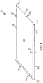
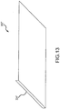
- the support plate 300 may include a body or base 304 with opposite top and bottom surfaces 308, 312, a plurality of corners or corner portions 316, and a plurality of outer edge segments 320 between adjacent corner portions 316, where the corner portions 316 and outer edge segments 320 collectively form an outer periphery or perimeter of the support plate 300.
- the base 304 may generally be in the form of a planar member that serves as a barrier between a building surface component 102 laid over the top surface 308 of the base 304 and the fixed surface below the building surface components 102 and that serves to inhibit movement of the building surface component 102 (or portions thereof) downwardly in a direction towards or to the fixed surface.
- this feature simplifies manufacture of the support plate 300, facilitates placement or location of a building surface component 102 over the top surface 308 of the support plate 300, allows for receipt of different sizes (e.g., widths, lengths) of building surface component 102, and the like.
- a plurality of support pedestals 201 may be located or placed upon a fixed surface (e.g., ground, rooftop, etc.) at the site with any appropriate (e.g. predetermined) spacing between the support pedestals 201.
- a fixed surface e.g., ground, rooftop, etc.
- any appropriate number of fixed and/or adjustable-height support pedestals 201 may be used and may be selected or configured so that the upper surfaces 220 of at least some adjacent ones of the support pedestals 201 are substantially coplanar.
- the method may then include positioning a building surface component 102 over and/or on each respective support plate 300 so that one of the outer edge segments 116 of the building surface component 102 abuts (e.g., full contact, near contact, etc.) the locating structure 324 of the first outer edge segment 320 1 of the support plate 300.
- the bottom surface 112 of the building surface component 102 may be laid over the top surface 308 of the support plate 300 so that the corner portions 110 of the building surface component 102 are generally adjacent (e.g., above) the corner portions 316 of the support plate 300.
- the corner portions 110 of the building surface component 102 may be supported by the upper surfaces 220 of the support pedestals 201.
- another outer edge segment 116 of the building surface component 102 may abut the locating structure 324 of the third outer edge segment 320 3 of the support plate 300.
- the building surface components 102 may be positioned over the support plates 300 at the site after the support plates 300 have already been positioned over the support pedestals 201.
- the building surface components 102 and support plates 300 may be separately transported to the site (e.g., whether as part of the same or different shipments) and then building surface components 102 may be positioned over the support plates 300 at the site (after the support plates 300 have already been positioned over the support pedestals 201).
- each support plate 300 may serve to provide additional support for the building surface component 102 laid thereover, reduce the likelihood of dropping or falling of the building surface component 102 or portions thereof in case of fracture or cracking of the building surface components 102 (e.g., towards or to the fixed surface), increase the overall durability of the elevated building surface assembly 100, and the like.
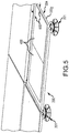
- the at least one adhesive may be in the form of one or more adhesive strips 400 (e.g., where each of opposing first and second surfaces of the adhesive strips 400 are adhesive or tacky) of any appropriate material (e.g., butyl rubber, as just one example) and of any appropriate dimensions (e.g., width, length, thickness) to cover at least a portion of the surface area of the top surface 308 of the support plate 300 and/or the bottom surface 112 of the building surface component 102 (e.g., at least about 5% of the surface area; not greater than about 90% of the surface area; etc.).
- any appropriate material e.g., butyl rubber, as just one example
- any appropriate dimensions e.g., width, length, thickness
- the adhesive may be in the form of a water-based (waterborne) adhesives, such as formulated from natural or synthetic polymers.
- the at least one adhesive 400 may be a hot adhesive (e.g., hot melt adhesive) such as a thermoplastic applied in molten form which solidifies on cooling to bond the building surface components 102 to the support plates 300.
- the at least one adhesive 400 may be in the form of a reactive adhesive such as a one-part adhesive that hardens via a chemical reaction with an external energy source (e.g., radiation, heat, moisture), a multi-component or part adhesive that hardens by mixing together two or more components that chemically react, or the like.
- a reactive adhesive such as a one-part adhesive that hardens via a chemical reaction with an external energy source (e.g., radiation, heat, moisture), a multi-component or part adhesive that hardens by mixing together two or more components that chemically react, or the like.
- a locating structure 324 need not necessarily extend along an entirety of a particular outer edge segment 320 of a support plate 300.
- the locating structure 324' of the first outer edge segment 320 1 ' may stop short of one or both of the corner portions 316' between which the first outer edge segment 320 1 ' extends to create a space 328 along the first outer edge segment 320 1 ' adjacent the corner portion 316' along which the locating structure 324' does not extend.
- first outer edge segment 320 1 ' may have spaces 328 adjacent both corner portions 316' between which the outer edge segments extend (e.g., see support plate 300'" of Figure 14 ).
- the spaces 328 may facilitate attachment of the support plate 300 to the support pedestals 201.
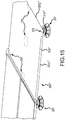
- any appropriate attachment apparatus or system 500 may be positioned into at least a portion of the space 328 and used to secure the support plate 300' to the upper surface 220 of the support pedestal 201.
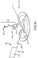
- the attachment system 500 may include an anchoring member 504 (e.g. plate such as a washer) with an aperture 512, and a threaded fastener 508 that is sized to be inserted through the aperture 512 and threaded into the upper surface 220 of the support pedestal 201.
- the anchoring member 504 may be placed over the top surface 308' of the support plate 300 adjacent a corner portion 316' of the support plate 300'.
- the fastener 508 may then be inserted through the aperture 512 and into the upper surface 220 of the support pedestal 201 until the head (not labeled) of the fastener 508 contacts the anchoring member 504and clamps the anchoring member 504 against the top surface 308' of the support plate 300' which thus clamps the support plate 300' against the upper surface 220 of the support pedestal 201. See Figure 10 .
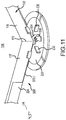
- the anchoring member 504 may include a notch 516 therein that may allow for rotation of the anchoring member 504 and alignment of the notch 516 with the support plate 300' (or another support plate 300 disposed over the upper surface 220 of the support pedestal 201) to allow for removal of the support plate 300' and building surface component 102 from the support pedestal 201 without having to first remove any other support plates 300 and building surface components 102 from the upper surface 220 of the support pedestal 201. See Figure 12 .
- the anchoring member 504 may be the same as that disclosed in U.S. Pat. No. 8,302,356 which is incorporated herein by reference in its entirety as if set forth in full.
- one or more of the support plates 300 may include one or more raised features or portions 700 that are configured to create a gap between a top surface 308 of the support plate 300 and the bottom surface 112 of the building surface component 102 (e.g., surface tile, paver, etc.) for receipt of the attachment system 500 therein to secure the support plate 300 and thus the surface tile 102 to the upper surface 220 of the support pedestal 201.
- the raised portion 700 may be generally disposed adjacent a corner portion 316 of the support plate 300 and arranged to extend upwardly away from the top surface 308 of the support plate 300 (e.g., in a direction opposite the support plate 220 ofthe support pedestal 201). An uppermost or top surface 708 of the raised portion 700 may be spaced from the corner portion 316 by a distance 716.
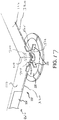
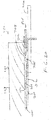
- the raised portion 700 maintains a gap 702 between the top surface 308 of the support plate 300 and the bottom surface 112 of the building surface component 102 (e.g., so as to space or separate the bottom surface 112 of the building surface component 102 from the top surface 308 of the support plate near the corner portions 110, 316). See Figures 17-19 .
- the gap 702 may begin at the corner portion 316 of the support plate 300 and extend inwardly to the uppermost portion 708 of the raised portion 700 along the distance 716 as well as at least partially down a length of at least one of first and second outer edge segments 116, 320 ofthe building surface component 102 and support plate 300.
- the gap 702 created by the raised portion 700 allows a user to selectively insert the attachment system 500 into the gap 702 while the building surface component 102 is attached to the top surface 308 of the support plate 300 and resting over the support pedestal.
- the raised portions 700 may be formed or disposed near one or more of the corner portions 316 of each surface tile 300 to create gaps 702 for receipt of one or more corresponding attachment systems 500.
- At least one adhesive 400 may be used to secure the bottom surface 112 of the building surface component 102 to the top surface 308 of the support plate 300.
- the adhesive 400 may generally not extend into the gap 702 along the distance 316 adjacent the corner portion 316 of the support plate 300 to allow the attachment apparatus or system 500 to be selectively positioned into at least a portion of the gap 702 to secure the support plate 300 to the upper surface 220 of the support pedestal 201.
- a gap 600 may be formed between the outer edge segments 320 of the support plate and an outer periphery of the adhesive. See Figures 5-6 .
- the gaps 702 and 600 may be at least partially overlapping.
- Figure 17 illustrates the anchoring member 504 of the attachment apparatus 500 being in a first rotational position whereby the anchoring member 504 is disposed outside of the gap 702 (e.g., where the notch 516 is generally aligned with the corner portions 116, 316). In this positon, the corner portions 116, 316 may be freely lifted away from or disposed onto the support plate 220 of the support pedestal 201.
- the surface tile 102 may be secured to the support plate 300 at any appropriate location (e.g., either at or away from the building site of the elevated flooring surface 101) and the resulting flooring unit 450 may be disposed over a plurality of support pedestals 201 (e.g., where the corner portions 110, 316 are disposed over the support plates 220 of the support pedestals 201).
- Figures 18-19 illustrate another rotational position of the anchoring member 504 whereby a portion of the anchoring member 504 is disposed within the gap 702 so as to limit lifting movement of the corner portions 116, 316 of the surface tile 102 and support plate 300 away from the support plate 220 of the support pedestal 201 (e.g., to limit movement of the flooring unit 450 away from the support pedestal 201).
- the raised portions 700 may be of any appropriate shape such as but not limited to circular, square, triangular, elongated, chevron, etc. When support plates 300 including one or more raised portions 700 are used, such support plates may have any appropriate number of locating structures 324 thereon or none at all.
- each of such two smaller building surface components 102 would include two corner portions 110 that are disposed over two corner portions 316 of the support plate and two other corner portions that generally abut the two other corner portions of the other smaller building surface component 102 (e.g., where one outer edge segment 116 of each smaller building surface component 102 would abut one outer edge segment 116 of the other smaller building surface component 102 over a central portion of the support plate 300).
- one or more raised portions 700 may be formed at the top surface 308 of the support plate 300 at or near locations other than the corner portions 316 of the support plate 300.
- one or more raised portions 700 may be formed near such locations such that the uppermost surfaces 708 are spaced inwardly from the outer edge segments 320 by a distance 712 to maintain a gap between the upper surface 308 of the support plate 300 and the bottom surface 112 of the surface tile 102 at such location for receipt of an attachment system 500.
- one or more markers e.g., indentations, notches, etc.
Landscapes
- Engineering & Computer Science (AREA)
- Architecture (AREA)
- General Engineering & Computer Science (AREA)
- Civil Engineering (AREA)
- Structural Engineering (AREA)
- Floor Finish (AREA)
Priority Applications (1)
| Application Number | Priority Date | Filing Date | Title |
|---|---|---|---|
| EP20182126.1A EP3739145B1 (fr) | 2016-09-16 | 2017-09-07 | Système de plaque de support pour des dalles de plancher surélevées |
Applications Claiming Priority (1)
| Application Number | Priority Date | Filing Date | Title |
|---|---|---|---|
| US15/267,326 US9683375B2 (en) | 2015-11-13 | 2016-09-16 | Support plate system for elevated flooring tiles |
Related Child Applications (1)
| Application Number | Title | Priority Date | Filing Date |
|---|---|---|---|
| EP20182126.1A Division EP3739145B1 (fr) | 2016-09-16 | 2017-09-07 | Système de plaque de support pour des dalles de plancher surélevées |
Publications (2)
| Publication Number | Publication Date |
|---|---|
| EP3296487A1 true EP3296487A1 (fr) | 2018-03-21 |
| EP3296487B1 EP3296487B1 (fr) | 2020-07-29 |
Family
ID=59811243
Family Applications (2)
| Application Number | Title | Priority Date | Filing Date |
|---|---|---|---|
| EP20182126.1A Active EP3739145B1 (fr) | 2016-09-16 | 2017-09-07 | Système de plaque de support pour des dalles de plancher surélevées |
| EP17189945.3A Active EP3296487B1 (fr) | 2016-09-16 | 2017-09-07 | Système de plaque de support pour des dalles de plancher surélevées |
Family Applications Before (1)
| Application Number | Title | Priority Date | Filing Date |
|---|---|---|---|
| EP20182126.1A Active EP3739145B1 (fr) | 2016-09-16 | 2017-09-07 | Système de plaque de support pour des dalles de plancher surélevées |
Country Status (1)
| Country | Link |
|---|---|
| EP (2) | EP3739145B1 (fr) |
Cited By (1)
| Publication number | Priority date | Publication date | Assignee | Title |
|---|---|---|---|---|
| IT201800004984A1 (it) * | 2018-05-02 | 2019-11-02 | Elemento antisfondamento per pavimentazioni sopraelevate e nuova pavimentazione sopraelevata rinforzata |
Citations (9)
| Publication number | Priority date | Publication date | Assignee | Title |
|---|---|---|---|---|
| EP0294212A2 (fr) * | 1987-06-05 | 1988-12-07 | Steelden (Manufacturing) Limited | Planchers surélevés |
| US6363685B1 (en) | 2000-05-19 | 2002-04-02 | William E. Kugler | Method and apparatus for selectively adjusting the elevation of an undulating or plannar surface |
| US20040261329A1 (en) | 2000-05-19 | 2004-12-30 | Kugler William E. | Apparatus for adjusting the elevation of a planar surface with threaded and non-threaded components |
| US20100000163A1 (en) * | 2008-07-01 | 2010-01-07 | Hong-I Tsai | Raised floor structure |
| US20110016809A1 (en) * | 2009-07-21 | 2011-01-27 | United Construction Products, Inc. | Support pedestal having an anchoring washer for securing elevated surface tiles |
| US8122612B2 (en) | 2008-08-31 | 2012-02-28 | United Construction Products, Inc. | System for indicating the engagement depth of threadably engaged surfaces |
| US8156694B2 (en) | 2009-07-31 | 2012-04-17 | United Construction Products, Inc. | Support pedestal for supporting an elevated building surface |
| US8898999B1 (en) | 2013-11-27 | 2014-12-02 | United Construction Products, Inc. | Restraint system for elevated surface tiles |
| US20150308126A1 (en) | 2014-04-29 | 2015-10-29 | United Construction Products, Inc. | Extended kerf cut and spline restraint system for elevated flooring surfaces |
-
2017
- 2017-09-07 EP EP20182126.1A patent/EP3739145B1/fr active Active
- 2017-09-07 EP EP17189945.3A patent/EP3296487B1/fr active Active
Patent Citations (10)
| Publication number | Priority date | Publication date | Assignee | Title |
|---|---|---|---|---|
| EP0294212A2 (fr) * | 1987-06-05 | 1988-12-07 | Steelden (Manufacturing) Limited | Planchers surélevés |
| US6363685B1 (en) | 2000-05-19 | 2002-04-02 | William E. Kugler | Method and apparatus for selectively adjusting the elevation of an undulating or plannar surface |
| US20040261329A1 (en) | 2000-05-19 | 2004-12-30 | Kugler William E. | Apparatus for adjusting the elevation of a planar surface with threaded and non-threaded components |
| US20100000163A1 (en) * | 2008-07-01 | 2010-01-07 | Hong-I Tsai | Raised floor structure |
| US8122612B2 (en) | 2008-08-31 | 2012-02-28 | United Construction Products, Inc. | System for indicating the engagement depth of threadably engaged surfaces |
| US20110016809A1 (en) * | 2009-07-21 | 2011-01-27 | United Construction Products, Inc. | Support pedestal having an anchoring washer for securing elevated surface tiles |
| US8302356B2 (en) | 2009-07-21 | 2012-11-06 | United Construction Products, Inc. | Support pedestal having an anchoring washer for securing elevated surface tiles |
| US8156694B2 (en) | 2009-07-31 | 2012-04-17 | United Construction Products, Inc. | Support pedestal for supporting an elevated building surface |
| US8898999B1 (en) | 2013-11-27 | 2014-12-02 | United Construction Products, Inc. | Restraint system for elevated surface tiles |
| US20150308126A1 (en) | 2014-04-29 | 2015-10-29 | United Construction Products, Inc. | Extended kerf cut and spline restraint system for elevated flooring surfaces |
Cited By (1)
| Publication number | Priority date | Publication date | Assignee | Title |
|---|---|---|---|---|
| IT201800004984A1 (it) * | 2018-05-02 | 2019-11-02 | Elemento antisfondamento per pavimentazioni sopraelevate e nuova pavimentazione sopraelevata rinforzata |
Also Published As
| Publication number | Publication date |
|---|---|
| EP3296487B1 (fr) | 2020-07-29 |
| EP3739145B1 (fr) | 2023-06-21 |
| EP3739145C0 (fr) | 2023-06-21 |
| EP3739145A1 (fr) | 2020-11-18 |
Similar Documents
| Publication | Publication Date | Title |
|---|---|---|
| US9951529B2 (en) | Support plate system for elevated flooring tiles | |
| US9874029B2 (en) | Support plate system for elevated flooring tiles | |
| US10280629B1 (en) | Restraint system for elevated flooring tiles | |
| US9038324B2 (en) | Field paver connector and restraining system | |
| EP2343419A1 (fr) | Dispositif d'alignement et de mise à niveau de tuile et procédé d'utilisation associé | |
| US8898999B1 (en) | Restraint system for elevated surface tiles | |
| US8695288B2 (en) | Structural systems for restraining elevated surface tiles | |
| US10041254B2 (en) | Tile and support structure | |
| US20160244979A1 (en) | Fasteners for pedestal supported tiles or decking | |
| US10988931B1 (en) | Tile and support structure | |
| US20150308126A1 (en) | Extended kerf cut and spline restraint system for elevated flooring surfaces | |
| US20240209634A1 (en) | Tile and support structure | |
| EP3739145B1 (fr) | Système de plaque de support pour des dalles de plancher surélevées | |
| US11085193B2 (en) | Peripheral restraint system for elevated flooring surface | |
| US11199007B2 (en) | Tile and support structure | |
| EP1856348A2 (fr) | Dispositif d'alignement et de mise a niveau de carreaux et son procede d'utilisation | |
| HK1163202A (en) | Tile alignment and leveling device and method for using the same | |
| HK1164956A (en) | Tile alignment and leveling device |
Legal Events
| Date | Code | Title | Description |
|---|---|---|---|
| PUAI | Public reference made under article 153(3) epc to a published international application that has entered the european phase |
Free format text: ORIGINAL CODE: 0009012 |
|
| STAA | Information on the status of an ep patent application or granted ep patent |
Free format text: STATUS: THE APPLICATION HAS BEEN PUBLISHED |
|
| AK | Designated contracting states |
Kind code of ref document: A1 Designated state(s): AL AT BE BG CH CY CZ DE DK EE ES FI FR GB GR HR HU IE IS IT LI LT LU LV MC MK MT NL NO PL PT RO RS SE SI SK SM TR |
|
| AX | Request for extension of the european patent |
Extension state: BA ME |
|
| STAA | Information on the status of an ep patent application or granted ep patent |
Free format text: STATUS: REQUEST FOR EXAMINATION WAS MADE |
|
| 17P | Request for examination filed |
Effective date: 20180903 |
|
| RBV | Designated contracting states (corrected) |
Designated state(s): AL AT BE BG CH CY CZ DE DK EE ES FI FR GB GR HR HU IE IS IT LI LT LU LV MC MK MT NL NO PL PT RO RS SE SI SK SM TR |
|
| GRAJ | Information related to disapproval of communication of intention to grant by the applicant or resumption of examination proceedings by the epo deleted |
Free format text: ORIGINAL CODE: EPIDOSDIGR1 |
|
| GRAP | Despatch of communication of intention to grant a patent |
Free format text: ORIGINAL CODE: EPIDOSNIGR1 |
|
| GRAP | Despatch of communication of intention to grant a patent |
Free format text: ORIGINAL CODE: EPIDOSNIGR1 |
|
| STAA | Information on the status of an ep patent application or granted ep patent |
Free format text: STATUS: GRANT OF PATENT IS INTENDED |
|
| INTG | Intention to grant announced |
Effective date: 20200220 |
|
| GRAS | Grant fee paid |
Free format text: ORIGINAL CODE: EPIDOSNIGR3 |
|
| GRAA | (expected) grant |
Free format text: ORIGINAL CODE: 0009210 |
|
| STAA | Information on the status of an ep patent application or granted ep patent |
Free format text: STATUS: THE PATENT HAS BEEN GRANTED |
|
| AK | Designated contracting states |
Kind code of ref document: B1 Designated state(s): AL AT BE BG CH CY CZ DE DK EE ES FI FR GB GR HR HU IE IS IT LI LT LU LV MC MK MT NL NO PL PT RO RS SE SI SK SM TR |
|
| REG | Reference to a national code |
Ref country code: CH Ref legal event code: EP |
|
| REG | Reference to a national code |
Ref country code: AT Ref legal event code: REF Ref document number: 1295969 Country of ref document: AT Kind code of ref document: T Effective date: 20200815 |
|
| REG | Reference to a national code |
Ref country code: IE Ref legal event code: FG4D |
|
| REG | Reference to a national code |
Ref country code: DE Ref legal event code: R096 Ref document number: 602017020459 Country of ref document: DE |
|
| REG | Reference to a national code |
Ref country code: LT Ref legal event code: MG4D |
|
| REG | Reference to a national code |
Ref country code: NL Ref legal event code: MP Effective date: 20200729 |
|
| REG | Reference to a national code |
Ref country code: AT Ref legal event code: MK05 Ref document number: 1295969 Country of ref document: AT Kind code of ref document: T Effective date: 20200729 |
|
| PG25 | Lapsed in a contracting state [announced via postgrant information from national office to epo] |
Ref country code: SE Free format text: LAPSE BECAUSE OF FAILURE TO SUBMIT A TRANSLATION OF THE DESCRIPTION OR TO PAY THE FEE WITHIN THE PRESCRIBED TIME-LIMIT Effective date: 20200729 Ref country code: BG Free format text: LAPSE BECAUSE OF FAILURE TO SUBMIT A TRANSLATION OF THE DESCRIPTION OR TO PAY THE FEE WITHIN THE PRESCRIBED TIME-LIMIT Effective date: 20201029 Ref country code: NO Free format text: LAPSE BECAUSE OF FAILURE TO SUBMIT A TRANSLATION OF THE DESCRIPTION OR TO PAY THE FEE WITHIN THE PRESCRIBED TIME-LIMIT Effective date: 20201029 Ref country code: AT Free format text: LAPSE BECAUSE OF FAILURE TO SUBMIT A TRANSLATION OF THE DESCRIPTION OR TO PAY THE FEE WITHIN THE PRESCRIBED TIME-LIMIT Effective date: 20200729 Ref country code: HR Free format text: LAPSE BECAUSE OF FAILURE TO SUBMIT A TRANSLATION OF THE DESCRIPTION OR TO PAY THE FEE WITHIN THE PRESCRIBED TIME-LIMIT Effective date: 20200729 Ref country code: FI Free format text: LAPSE BECAUSE OF FAILURE TO SUBMIT A TRANSLATION OF THE DESCRIPTION OR TO PAY THE FEE WITHIN THE PRESCRIBED TIME-LIMIT Effective date: 20200729 Ref country code: PT Free format text: LAPSE BECAUSE OF FAILURE TO SUBMIT A TRANSLATION OF THE DESCRIPTION OR TO PAY THE FEE WITHIN THE PRESCRIBED TIME-LIMIT Effective date: 20201130 Ref country code: LT Free format text: LAPSE BECAUSE OF FAILURE TO SUBMIT A TRANSLATION OF THE DESCRIPTION OR TO PAY THE FEE WITHIN THE PRESCRIBED TIME-LIMIT Effective date: 20200729 Ref country code: ES Free format text: LAPSE BECAUSE OF FAILURE TO SUBMIT A TRANSLATION OF THE DESCRIPTION OR TO PAY THE FEE WITHIN THE PRESCRIBED TIME-LIMIT Effective date: 20200729 Ref country code: GR Free format text: LAPSE BECAUSE OF FAILURE TO SUBMIT A TRANSLATION OF THE DESCRIPTION OR TO PAY THE FEE WITHIN THE PRESCRIBED TIME-LIMIT Effective date: 20201030 |
|
| PG25 | Lapsed in a contracting state [announced via postgrant information from national office to epo] |
Ref country code: LV Free format text: LAPSE BECAUSE OF FAILURE TO SUBMIT A TRANSLATION OF THE DESCRIPTION OR TO PAY THE FEE WITHIN THE PRESCRIBED TIME-LIMIT Effective date: 20200729 Ref country code: PL Free format text: LAPSE BECAUSE OF FAILURE TO SUBMIT A TRANSLATION OF THE DESCRIPTION OR TO PAY THE FEE WITHIN THE PRESCRIBED TIME-LIMIT Effective date: 20200729 Ref country code: RS Free format text: LAPSE BECAUSE OF FAILURE TO SUBMIT A TRANSLATION OF THE DESCRIPTION OR TO PAY THE FEE WITHIN THE PRESCRIBED TIME-LIMIT Effective date: 20200729 Ref country code: IS Free format text: LAPSE BECAUSE OF FAILURE TO SUBMIT A TRANSLATION OF THE DESCRIPTION OR TO PAY THE FEE WITHIN THE PRESCRIBED TIME-LIMIT Effective date: 20201129 |
|
| PG25 | Lapsed in a contracting state [announced via postgrant information from national office to epo] |
Ref country code: NL Free format text: LAPSE BECAUSE OF FAILURE TO SUBMIT A TRANSLATION OF THE DESCRIPTION OR TO PAY THE FEE WITHIN THE PRESCRIBED TIME-LIMIT Effective date: 20200729 |
|
| PG25 | Lapsed in a contracting state [announced via postgrant information from national office to epo] |
Ref country code: SM Free format text: LAPSE BECAUSE OF FAILURE TO SUBMIT A TRANSLATION OF THE DESCRIPTION OR TO PAY THE FEE WITHIN THE PRESCRIBED TIME-LIMIT Effective date: 20200729 Ref country code: EE Free format text: LAPSE BECAUSE OF FAILURE TO SUBMIT A TRANSLATION OF THE DESCRIPTION OR TO PAY THE FEE WITHIN THE PRESCRIBED TIME-LIMIT Effective date: 20200729 Ref country code: CZ Free format text: LAPSE BECAUSE OF FAILURE TO SUBMIT A TRANSLATION OF THE DESCRIPTION OR TO PAY THE FEE WITHIN THE PRESCRIBED TIME-LIMIT Effective date: 20200729 Ref country code: DK Free format text: LAPSE BECAUSE OF FAILURE TO SUBMIT A TRANSLATION OF THE DESCRIPTION OR TO PAY THE FEE WITHIN THE PRESCRIBED TIME-LIMIT Effective date: 20200729 Ref country code: RO Free format text: LAPSE BECAUSE OF FAILURE TO SUBMIT A TRANSLATION OF THE DESCRIPTION OR TO PAY THE FEE WITHIN THE PRESCRIBED TIME-LIMIT Effective date: 20200729 |
|
| REG | Reference to a national code |
Ref country code: CH Ref legal event code: PL Ref country code: DE Ref legal event code: R097 Ref document number: 602017020459 Country of ref document: DE |
|
| RAP4 | Party data changed (patent owner data changed or rights of a patent transferred) |
Owner name: UNITED CONSTRUCTION PRODUCTS, LLC |
|
| PG25 | Lapsed in a contracting state [announced via postgrant information from national office to epo] |
Ref country code: AL Free format text: LAPSE BECAUSE OF FAILURE TO SUBMIT A TRANSLATION OF THE DESCRIPTION OR TO PAY THE FEE WITHIN THE PRESCRIBED TIME-LIMIT Effective date: 20200729 |
|
| PLBE | No opposition filed within time limit |
Free format text: ORIGINAL CODE: 0009261 |
|
| STAA | Information on the status of an ep patent application or granted ep patent |
Free format text: STATUS: NO OPPOSITION FILED WITHIN TIME LIMIT |
|
| REG | Reference to a national code |
Ref country code: BE Ref legal event code: MM Effective date: 20200930 |
|
| PG25 | Lapsed in a contracting state [announced via postgrant information from national office to epo] |
Ref country code: SK Free format text: LAPSE BECAUSE OF FAILURE TO SUBMIT A TRANSLATION OF THE DESCRIPTION OR TO PAY THE FEE WITHIN THE PRESCRIBED TIME-LIMIT Effective date: 20200729 Ref country code: LU Free format text: LAPSE BECAUSE OF NON-PAYMENT OF DUE FEES Effective date: 20200907 |
|
| 26N | No opposition filed |
Effective date: 20210430 |
|
| PG25 | Lapsed in a contracting state [announced via postgrant information from national office to epo] |
Ref country code: FR Free format text: LAPSE BECAUSE OF NON-PAYMENT OF DUE FEES Effective date: 20200929 |
|
| PG25 | Lapsed in a contracting state [announced via postgrant information from national office to epo] |
Ref country code: IE Free format text: LAPSE BECAUSE OF NON-PAYMENT OF DUE FEES Effective date: 20200907 Ref country code: LI Free format text: LAPSE BECAUSE OF NON-PAYMENT OF DUE FEES Effective date: 20200930 Ref country code: SI Free format text: LAPSE BECAUSE OF FAILURE TO SUBMIT A TRANSLATION OF THE DESCRIPTION OR TO PAY THE FEE WITHIN THE PRESCRIBED TIME-LIMIT Effective date: 20200729 Ref country code: BE Free format text: LAPSE BECAUSE OF NON-PAYMENT OF DUE FEES Effective date: 20200930 Ref country code: CH Free format text: LAPSE BECAUSE OF NON-PAYMENT OF DUE FEES Effective date: 20200930 |
|
| PG25 | Lapsed in a contracting state [announced via postgrant information from national office to epo] |
Ref country code: TR Free format text: LAPSE BECAUSE OF FAILURE TO SUBMIT A TRANSLATION OF THE DESCRIPTION OR TO PAY THE FEE WITHIN THE PRESCRIBED TIME-LIMIT Effective date: 20200729 Ref country code: MT Free format text: LAPSE BECAUSE OF FAILURE TO SUBMIT A TRANSLATION OF THE DESCRIPTION OR TO PAY THE FEE WITHIN THE PRESCRIBED TIME-LIMIT Effective date: 20200729 Ref country code: CY Free format text: LAPSE BECAUSE OF FAILURE TO SUBMIT A TRANSLATION OF THE DESCRIPTION OR TO PAY THE FEE WITHIN THE PRESCRIBED TIME-LIMIT Effective date: 20200729 |
|
| PG25 | Lapsed in a contracting state [announced via postgrant information from national office to epo] |
Ref country code: MK Free format text: LAPSE BECAUSE OF FAILURE TO SUBMIT A TRANSLATION OF THE DESCRIPTION OR TO PAY THE FEE WITHIN THE PRESCRIBED TIME-LIMIT Effective date: 20200729 Ref country code: MC Free format text: LAPSE BECAUSE OF FAILURE TO SUBMIT A TRANSLATION OF THE DESCRIPTION OR TO PAY THE FEE WITHIN THE PRESCRIBED TIME-LIMIT Effective date: 20200729 |
|
| PGFP | Annual fee paid to national office [announced via postgrant information from national office to epo] |
Ref country code: DE Payment date: 20250929 Year of fee payment: 9 |
|
| PGFP | Annual fee paid to national office [announced via postgrant information from national office to epo] |
Ref country code: IT Payment date: 20250919 Year of fee payment: 9 |
|
| PGFP | Annual fee paid to national office [announced via postgrant information from national office to epo] |
Ref country code: GB Payment date: 20250929 Year of fee payment: 9 |