EP3296513B1 - Surveillance de l'état d'une hélice - Google Patents
Surveillance de l'état d'une hélice Download PDFInfo
- Publication number
- EP3296513B1 EP3296513B1 EP16306183.1A EP16306183A EP3296513B1 EP 3296513 B1 EP3296513 B1 EP 3296513B1 EP 16306183 A EP16306183 A EP 16306183A EP 3296513 B1 EP3296513 B1 EP 3296513B1
- Authority
- EP
- European Patent Office
- Prior art keywords
- propeller
- pitch angle
- residual
- threshold
- health
- Prior art date
- Legal status (The legal status is an assumption and is not a legal conclusion. Google has not performed a legal analysis and makes no representation as to the accuracy of the status listed.)
- Active
Links
Images




Classifications
-
- B—PERFORMING OPERATIONS; TRANSPORTING
- B64—AIRCRAFT; AVIATION; COSMONAUTICS
- B64D—EQUIPMENT FOR FITTING IN OR TO AIRCRAFT; FLIGHT SUITS; PARACHUTES; ARRANGEMENT OR MOUNTING OF POWER PLANTS OR PROPULSION TRANSMISSIONS IN AIRCRAFT
- B64D45/00—Aircraft indicators or protectors not otherwise provided for
-
- B—PERFORMING OPERATIONS; TRANSPORTING
- B64—AIRCRAFT; AVIATION; COSMONAUTICS
- B64C—AEROPLANES; HELICOPTERS
- B64C11/00—Propellers, e.g. of ducted type; Features common to propellers and rotors for rotorcraft
- B64C11/30—Blade pitch-changing mechanisms
-
- F—MECHANICAL ENGINEERING; LIGHTING; HEATING; WEAPONS; BLASTING
- F01—MACHINES OR ENGINES IN GENERAL; ENGINE PLANTS IN GENERAL; STEAM ENGINES
- F01D—NON-POSITIVE DISPLACEMENT MACHINES OR ENGINES, e.g. STEAM TURBINES
- F01D7/00—Rotors with blades adjustable in operation; Control thereof
-
- G—PHYSICS
- G07—CHECKING-DEVICES
- G07C—TIME OR ATTENDANCE REGISTERS; REGISTERING OR INDICATING THE WORKING OF MACHINES; GENERATING RANDOM NUMBERS; VOTING OR LOTTERY APPARATUS; ARRANGEMENTS, SYSTEMS OR APPARATUS FOR CHECKING NOT PROVIDED FOR ELSEWHERE
- G07C5/00—Registering or indicating the working of vehicles
- G07C5/08—Registering or indicating performance data other than driving, working, idle, or waiting time, with or without registering driving, working, idle or waiting time
- G07C5/0816—Indicating performance data, e.g. occurrence of a malfunction
-
- B—PERFORMING OPERATIONS; TRANSPORTING
- B64—AIRCRAFT; AVIATION; COSMONAUTICS
- B64D—EQUIPMENT FOR FITTING IN OR TO AIRCRAFT; FLIGHT SUITS; PARACHUTES; ARRANGEMENT OR MOUNTING OF POWER PLANTS OR PROPULSION TRANSMISSIONS IN AIRCRAFT
- B64D45/00—Aircraft indicators or protectors not otherwise provided for
- B64D2045/0085—Devices for aircraft health monitoring, e.g. monitoring flutter or vibration
-
- F—MECHANICAL ENGINEERING; LIGHTING; HEATING; WEAPONS; BLASTING
- F05—INDEXING SCHEMES RELATING TO ENGINES OR PUMPS IN VARIOUS SUBCLASSES OF CLASSES F01-F04
- F05D—INDEXING SCHEME FOR ASPECTS RELATING TO NON-POSITIVE-DISPLACEMENT MACHINES OR ENGINES, GAS-TURBINES OR JET-PROPULSION PLANTS
- F05D2260/00—Function
- F05D2260/80—Diagnostics
-
- Y—GENERAL TAGGING OF NEW TECHNOLOGICAL DEVELOPMENTS; GENERAL TAGGING OF CROSS-SECTIONAL TECHNOLOGIES SPANNING OVER SEVERAL SECTIONS OF THE IPC; TECHNICAL SUBJECTS COVERED BY FORMER USPC CROSS-REFERENCE ART COLLECTIONS [XRACs] AND DIGESTS
- Y02—TECHNOLOGIES OR APPLICATIONS FOR MITIGATION OR ADAPTATION AGAINST CLIMATE CHANGE
- Y02T—CLIMATE CHANGE MITIGATION TECHNOLOGIES RELATED TO TRANSPORTATION
- Y02T50/00—Aeronautics or air transport
- Y02T50/60—Efficient propulsion technologies, e.g. for aircraft
Definitions
- This disclosure relates to the technical area of health monitoring of vehicle engine propellers, in particular in aircraft, for providing a warning or an indication that maintenance is required.
- the field of the disclosure lies in the area of aircraft engine propellers.
- US 8,532,939 B2 discloses a system which measures the time of arrival of each blade of a fan at a certain position around the path of travel of the blade, and compares this with expected times of arrival of each blade. From the discrepancy between these, the system calculates the blade resonant frequencies and a comparison can be made to those of a "healthy blade", to determine if there is blade damage.
- US 2012/0045330 A1 teaches illuminating a wind turbine with a light source, building a 3-dimensional image of the wind turbine using backscattered light pulses and comparing this image with another to determine from the deviations if the health of the wind turbine has been compromised.
- US 5779446 discloses an air driven turbine including a blade pitch control system.
- the present disclosure aims to provide an alternative and simple real-time health monitoring system for one or more propellers.
- a propeller control is configured to change the pitch angle of all the blades of the propeller in order to maintain a constant speed of rotation of the propeller, the method comprising: receiving a first propeller pitch angle of a first propeller of an aircraft; receiving a second propeller pitch angle; wherein pitch angle is an average pitch angle of the blades of the propeller; calculating a first residual pitch angle which is the difference between the first propeller pitch angle and a second propeller pitch angle wherein the first propeller pitch angle and the second propeller pitch angle are for a propeller at the same operating conditions; and comparing the first residual pitch angle to at least one threshold; characterised in that the second propeller pitch angle is either a pitch angle of a second propeller of the aircraft or a predicted pitch angle generated by a computer model, and the method further comprises establishing that the health of the propeller
- the method may comprise establishing that the health of the propeller may be impaired if the residual pitch angle is above the at least one threshold.
- the at least one threshold may include upper and lower thresholds.
- the health of the propeller may be impaired if the residual pitch angle exceeds the upper threshold or is below the lower threshold.
- the method may further comprise indicating an alert for maintenance if it is established that the health of the propeller may be impaired.
- the method may further comprise: receiving a third propeller pitch angle of a second propeller of the aircraft; calculating a second residual pitch angle which is the difference between the first and third propeller pitch angles; and comparing the second residual pitch angle to at least one threshold.
- the method may comprise comparing the second residual pitch angle to upper and lower thresholds.
- the at least one threshold for the residual pitch angle may be between 0.1° to 5°, optionally between 0.2° to 2°.
- the at least one threshold for the residual pitch angle may be between 0.3° to 1°.
- the at least one threshold for the residual pitch angle may be 0.5°.
- the upper and lower thresholds for the residual pitch angle may be between +0.1° to +5° and between -0.1° to -5° respectively.
- the upper and lower thresholds for the residual pitch angle may be between +0.2° to +2° and between -0.2° to -2° respectively.
- the upper and lower thresholds for the residual pitch angle may be between +0.3° to +1° and between -0.3° to -1° respectively.
- the upper and lower thresholds for the residual pitch angle may be +0.5° and -0.5° respectively.
- the method may further comprise: receiving propeller pitch angles of further propellers of the same aircraft; calculating further residual pitch angles which are the difference between pairs of propeller pitch angles; comparing the further residual pitch angles to the upper and lower thresholds; and establishing that the health of a propeller may be impaired if multiple residual pitch angles are outside of a range defined between the lower and upper thresholds, said residual pitch angles having been calculated using data from one or more common propellers.
- the method may further comprise indicating an alert for maintenance if it is established that the health of a propeller may be impaired.
- an apparatus comprising a processor arranged to carry out the method according to the first aspect.
- the processor may be integrated into the FADEC.
- the apparatus may further comprise a propeller blade pitch angle detector.
- a first embodiment of the present disclosure of a real-time fault detection and isolation algorithm can be best described with reference to Figures 1 and 2 .
- Data relating to the pitch angle of aircraft propeller blades is conventionally collected by an aircraft. This may for example be through the use of a magnetic pickup and metallic target system and supplied to an electronic control system. For example, as the propeller rotates, metallic targets on the propeller blades pass through a magnetic field generated by the pickups and generate an electrical pulse train that can be measured by the control unit. This pulse train comprises data which, when properly calibrated, comprises meaningful data of the angle of pitch of blades on the propeller.
- Other means for collecting the pitch angle data include using a Linear Variable Differential Transformer, LVDT or using a Rotary Variable Differential Transformer, RVDT.
- the angle of pitch of propeller blades varies depending on the shaft horsepower of the engine.
- Figure 1 shows how a measured propeller pitch angle 10 varies depending on the shaft horsepower of an aircraft engine.
- pitch angle or “pitch angle data” of a propeller, what is meant is an average pitch angle, or data representing the average pitch angle (rotation about a longitudinal axis of a blade) of the blades on a propeller.
- the pitch angle of a propeller will also fluctuate with time, due to operating conditions (such as the engine shaft horsepower) and due to damage.
- damage to a propeller can occur, i.e. the health of the propeller may be impaired. This can be due, for example, to high loading during abnormal propeller operations, adverse weather conditions, bird strike or the like.
- the result of this damage is degradation of the impacted blade, which effectively causes a change of shape of the blade.
- This change of shape affects the proportion of the engine driving torque which is reacted by the blade.
- the proportion of engine driving torque which is reacted by the blade may increase or decrease. Consequently, since the engine driving torque is maintained at a constant value, the propeller control changes the pitch angle of all of the propeller blades on the propeller, in order to maintain constant speed of rotation of the propeller.
- the change in the amount of torque reacted by the degraded blade is compensated by changing the pitch angle of all of the blades. Accordingly, the average blade pitch across the entire propeller will be altered and this can be measured.
- predicted propeller pitch angle data 20 is also shown in the graph of Figure 1 .
- This predetermined data which is either calculated by a computer model or is stored propeller data for a healthy (i.e. undamaged) propeller, is based on a healthy propeller at specific flight and operation conditions. Where the conditions of the aircraft match those of the predetermined model data, then it is to be expected that unless the propeller is damaged, the two data sets should be relatively closely aligned. This can be seen in Figure 1 , where the two data sets 10 and 20 are closely aligned.
- the graph depicts residual pitch angle data 30.
- the residual pitch angle at a particular point in time is calculated by subtracting one of the measured or predetermined pitch angles from the other, i.e. by finding the difference between the predicted or predetermined pitch angle 20 for a healthy propeller and the actual measured pitch angle 10 from the propeller. By calculating this for a number of points in time, a residual pitch angle dataset 30 (also indicated as "Delta pitch”) can be obtained and plotted as in Figure 2 .
- the present inventor has recognised that the health of a propeller can be assessed by comparing the residual pitch angle with a threshold.
- the pitch angle of the propeller blades as compensated by the controller may be increased or decreased. Accordingly, it is necessary to set both a predetermined upper threshold 40 and a predetermined lower threshold 50 for the residual pitch angle data, as shown in Figure 2 .
- the predetermined upper and lower thresholds may be +0.5° and -0.5° respectively as shown in the Figures.
- the upper and lower thresholds may be between +0.1° to +5° and between -0.1° to -5° respectively, optionally between +0.2° to +2° and between -0.2° to -2° respectively, further optionally between +0.3° to +1° and between -0.3° to -1° respectively.
- the upper and lower thresholds may have the same numerical value, for example, they may be +0.4° and -0.4° respectively, +0.5° and -0.5° respectively or +0.6° and -0.6° respectively.
- the propeller may be (or has been) damaged, i.e. the health of the propeller may be impaired, because the pitch of the propeller is significantly outside of an expected healthy propeller pitch range.
- the calculated residual pitch angle reduces below the predetermined lower threshold (i.e. the residual pitch angle data curve 30 as shown in Figure 2 extends at any point below the lower threshold 50)
- the propeller may be (or has been) damaged, i.e. the health of the propeller may be impaired, because the pitch angle of the propeller is significantly outside of an expected healthy propeller pitch range.
- a control unit (not shown) is arranged to generate a maintenance alert to notify personnel that the propeller should be inspected, to assess the extent of the damage and to carry out any necessary repairs.
- the above method can be carried out in real-time throughout propeller operation for each of the propellers of an aircraft and can thus ensure that inspection and maintenance checks are scheduled when required and not unnecessarily. It also enables potential issues to be discovered as and when they occur, rather than awaiting the next maintenance check.
- a full automation of the process could involve a computer and/or processing device, which may be integrated into the FADEC (Full Authority Digital Engine Control) of the aircraft, that automatically calculates or recovers the propeller's pitch angles and then automatically calculates the residual propeller pitch angle using propeller pitch angle data for the same operating conditions.
- the process may automatically provide reports describing the state of the propeller blades and/or alert the operator if necessary and/or send a message to notify personnel of the need for inspection and possible maintenance.
- the method of the first embodiment is especially useful where the predetermined predicted propeller pitch angle data 20 is for a propeller at the same flight and operating conditions as the actual propeller at that point, or if propeller pitch angle data is easily predictable for the particular flight and operating conditions.
- the aircraft is in different flight and operating conditions than those of the predicted data so such comparisons may not be particularly indicative of a damaged propeller, or that pitch angle data may not easily be predicted for the particular conditions.
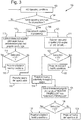
- FIG 3 shows the above method of the first embodiment via branch 110 as well as a method of the second embodiment of the disclosure via branch 120.
- a method for monitoring aircraft propeller health 100 implemented by a control unit begins with a step 102 of determining the particular operating conditions of the aircraft, i.e. checking for stabilised flight steady state conditions. This can include using aircraft parameters such as sideslip, roll, yaw, pitch, etc., as well as the engine shaft horsepower (SHP), the propeller rotational speed, etc..
- the control unit confirms that the operating conditions identified in step 102 are the same for all propellers, i.e. that the flight conditions are stable. The method does not proceed to step 106 until this has been confirmed.
- the pitch angle of the propellers is recorded, received for example from conventional pitch angle detection technology. This may be for one or more propellers, and optionally for all of the propellers. From step 106, the method divides into two separate branches, 110 and 120. It is contemplated that the method can include either branch 110 or 120, or that it can include both branches.
- the method following branch 110 is that described above for the first embodiment. It can be carried out for each individual propeller, optionally for each of multiple propellers and further optionally for each and every propeller of the aircraft.
- step 112 the difference between the measured pitch angle of the propeller and a predetermined predicted propeller pitch angle for a nominally healthy propeller under the same operating conditions is established. This is done by subtraction of one pitch angle from the other, resulting in a residual pitch angle ("delta pitch").
- the residual pitch angle is compared with upper and lower thresholds. If the residual pitch angle falls between the upper and lower thresholds, then it is concluded that the propeller is healthy, i.e. has blades in a healthy condition, at step 116.
- the propeller may have or has damaged blades (i.e. that the health of the propeller may be impaired) at step 118.
- the method following branch 120 is that of the second embodiment and is useful, for example, in cases where the operating conditions of the aircraft are not the same as or similar to those of the predetermined predicted model data, or where it is difficult to make predictions for the expected pitch angle of a healthy blade under the particular operating conditions.
- the method in branch 120 starts at step 121, by finding the difference between the measured pitch angles of different propellers. This is usually done by subtraction. For example, if there are four propellers P1, P2, P3, P4 having respective pitch angles p1, p2, p3 and p4, then the following six residual pitch angle combinations are possible: p1-p2; p1-p3; p1-p4; p2-p3; p2-p4; p3-p4. These are shown plotted over time on the graph of Figure 4 as residual pitch angle data sets 210, 220, 230, 240, 250 and 260 respectively.
- the residual pitch angle is compared with predetermined upper and lower thresholds.
- these thresholds may only be useful when the residual pitch angles arise from comparing propeller pitch angles from engines which are acting in a symmetric fashion, i.e. under symmetric operating conditions.
- pitch angle comparisons may only be made between propellers of the same type of engine, i.e. inboard or outboard engines.
- Figure 7 depicts schematically the residual pitch angle data sets 510, 520, 530, 540, 550 and 560 (showing residual pitch angle over time) on a graph, where at least some of the residual pitch angles in residual pitch angle data sets 520, 540, 560 fall outside of the thresholds 570, 580. Accordingly, there is potentially a problem with at least one propeller, which is established at step 124 of the method 100 of Figure 3 .
- the residual pitch angles in residual pitch angle data sets 520, 540 and 560 which fall outside the thresholds 570, 580 relate to propeller pitch angle comparisons p1-p3, p2-p3 and p3-p4 respectively.
- the residual pitch angles in residual pitch angle data sets 510, 530 and 550 within the thresholds 570, 580 relate to propeller pitch angle comparisons p1-p2, p1-p4 and p2-p4 respectively.
- the healthy propellers which have residual pitch angles within the thresholds 570, 580 are propellers P1, P2 and P4. It can also be seen that any comparisons of propeller pitch angle which involve propeller P3 having a propeller pitch angle of p3 result in a significantly large residual pitch angle beyond the threshold limits 570, 580. Accordingly, the potentially damaged propeller can be identified as being P3.
- Determination of which propellers are healthy and which are damaged may additionally be part of method step 124 of Figure 3 . However, it can help to optimize inspection time by carrying out the verification step 125 (discussed further below), since in many cases, this can help to pinpoint which of several propellers requires inspection. Thus, there is the possibility that in addition to comparisons being made between propellers using the above-described method of calculating a residual pitch angle to indicate the degree of similarity and/or difference between propellers, subsequent verification can also take place.
- step 124 a particular residual angle is found to fall outside of the threshold, it can be easily determined which two propellers provided the residual angle and thus one is potentially damaged. If no further analysis is carried out at this stage, then two propellers need to be inspected; however if verification is carried out, it may be discovered that only one propeller is damaged and thus only one inspection takes place.
- An alternative example is as discussed below in relation to Figure 5 , where not all of the possible residual pitch angles have been calculated initially. It may be necessary in the course of the analysis to calculate a further residual angle and so step 125 is required. Thus it is clear that although the method may stop at step 124, it can often be beneficial in reducing inspection time and costs to continue to step 125.
- a residual pitch angle is calculated between the potentially damaged propeller and either predetermined predicted pitch angle data as in step 112 above (particularly if the correct flight conditions allow for it), or a propeller which is most probably a healthy propeller.
- step 125 is carried out for each of those potentially unhealthy propellers.
- this step may involve merely referring back to a previously calculated residual pitch angle, or, as will be described below with reference to Figures 5 and 6 , may require a further residual pitch angle to be calculated.
- the residual pitch angle is compared with the predetermined upper and lower thresholds. If the residual pitch angle falls between the lower and upper thresholds, then at step 127, it is concluded that the propeller is healthy. Conversely, if the residual pitch angle is outside of the thresholds, i.e. above the upper threshold or below the lower threshold, then it is concluded at step 128 that the propeller is damaged (i.e. its health is impaired).
- branches 110 and 120 of the method once it has been established by the system that a certain propeller is damaged (i.e. has at least one damaged blade and thus its health is impaired), the control unit will send an alert that inspection and potentially maintenance is required for that particular propeller.
- propeller pitch angle comparisons are to minimise the calculations required, by making an incomplete set of comparisons. This may be beneficial in terms of time and capacity for data calculation and storage, especially if the method is operating in real-time.
- propellers P1, P2, P3 and P4 although there are four propellers P1, P2, P3 and P4 and so potentially six different pitch angle comparisons could be made, it may be desirable to reduce computation requirements by only making four pitch angle comparisons.
- each propeller is compared to two others, thus residual pitch angle p1-p2 is depicted over time by residual pitch angle data set 310, residual pitch angle p1-p4 is depicted over time by residual pitch angle data set 330, residual pitch angle p2-p3 is depicted over time by residual pitch angle data set 340 and residual pitch angle p3-p4 is depicted over time by residual pitch angle data set 360.
- Upper threshold 370 and lower threshold 380 are also shown.
- Figure 6 depicts the residual pitch angles over time for the case where all four propellers are damaged.
- propellers P1, P2 and P4 all have one damaged blade, while propeller P3 has three damaged blades.
- residual pitch angle data set 410 shows residual pitch angle p1-p2 over time
- residual pitch angle data set 430 shows residual pitch angle p1-p4 over time
- data set 440 shows residual pitch angle p2-p3 over time
- residual pitch angle data set 460 shows residual pitch angle p3-p4 over time.
- the upper threshold is given by 470 and the lower threshold by 480.
- the residual pitch angle data sets 410 and 430 show residual pitch angles completely within the thresholds, i.e. between threshold 470 and threshold 480. It can be seen therefore from residual pitch angle data set 410 that propellers P1 and P2 are in a similar state of health, and from residual pitch angle data set 430 that propellers P1 and P4 are also in a similar state of health. However, it is clear from residual pitch angle data sets 440 and 460 which show residual pitch angles lying outside the thresholds 470 and 480 respectively that propellers P2 and P3 are in very different states of health, as are propellers P3 and P4. Thus, in conclusion from this data, propellers P1, P2 and P4 are in a similar state of health, while propeller P3 is in a different state of health.
- propeller P3 it is not possible to definitely conclude whether only propeller P3 is damaged or if all of the propellers are damaged.
- all of propellers P1, P2 and P4 had incurred damage to one blade, while propeller P3 had incurred damage to three blades.
- propeller P3 was relatively more damaged that propellers P1, P2 and P4, which were all relatively similarly damaged.
- a control unit sends an alert for a visual inspection and maintenance to be carried out.
- the resultant residual pitch angle when calculating residual pitch angle, depending which pitch angle is subtracted from the other, the resultant residual pitch angle may be positive or negative. In any case, there is no need to be particular when choosing the order for subtraction, since the above methodology is not particularly concerned with whether the residual pitch angle is positive or negative, rather its amplitude. The reason for this is that depending on the particular damage to a propeller, the blades may readjust to compensate for the torque reacted (see description above) by changing the pitch angle in either direction of rotation. Accordingly, the important factor being assessed in the above methodology is the amplitude of the difference in pitch angle and not the direction of pitch change.
- a method could comprise calculating a residual pitch angle and subsequently taking the absolute value (i.e. the modulus) of this calculated residual pitch angle.
- These absolute values of residual pitch angle will range from 0° upwards. Accordingly, only one threshold, an upper threshold is required, e.g. at 0.5°.
- the pitch angle of propellers is already measured using pre-existing hardware.
- the present method and apparatus does not require additional measuring equipment, thereby providing a simple and weight-saving solution for monitoring aircraft health. Additionally, no extra instrumentation is required on rotating or static parts.
Landscapes
- Engineering & Computer Science (AREA)
- Aviation & Aerospace Engineering (AREA)
- Mechanical Engineering (AREA)
- General Engineering & Computer Science (AREA)
- Physics & Mathematics (AREA)
- General Physics & Mathematics (AREA)
- Wind Motors (AREA)
Claims (14)
- Procédé de surveillance de l'état d'une hélice d'aéronef (100) dans lequel en réponse à un changement de couple provoqué par une pale détériorée d'une hélice de l'aéronef, une commande d'hélice est configurée pour modifier l'angle de pas de toutes les pales de l'hélice afin de maintenir une vitesse de rotation constante de l'hélice, le procédé comprenant :la réception (106) d'un premier angle de pas d'hélice (10) d'une première hélice d'un aéronef ;la réception d'un deuxième angle de pas d'hélice (20) ;dans lequel l'angle de pas est un angle de pas moyen des pales de l'hélice ;le calcul (112, 121) d'un premier angle de pas résiduel (30, 210, 220, 230, 240, 250, 260) qui est la différence entre le premier angle de pas d'hélice et un deuxième angle de pas d'hélice (20) dans lequel le premier angle de pas d'hélice et le deuxième angle de pas d'hélice sont pour une hélice dans les mêmes conditions de fonctionnement ; etla comparaison (114, 122) du premier angle de pas résiduel à au moins un seuil ;caractérisé en ce que le deuxième angle de pas d'hélice est soit un angle de pas d'une seconde hélice de l'aéronef, soit un angle de pas prévu généré par un modèle informatique, etle procédé comprend en outre le fait d'établir (118, 124) que l'état de l'hélice peut être altéré si l'angle de pas résiduel est en dehors de l'au moins un seuil.
- Procédé selon la revendication 1, dans lequel l'au moins un seuil pour l'angle de pas résiduel est compris entre 0,1 ° et 5 °.
- Procédé selon la revendication 1 ou 2, comprenant en outre le fait d'établir (118, 124) que l'état de l'hélice peut être altéré si l'angle de pas résiduel est en dehors de l'au moins un seuil.
- Procédé selon la revendication 1, dans lequel l'au moins un seuil comporte des seuils supérieur (40, 270) et inférieur (50, 280).
- Procédé selon la revendication 4, dans lequel les seuils supérieur et inférieur pour l'angle de pas résiduel sont compris entre +0,1 ° et +5 ° et entre -0,1 ° et -5 ° respectivement.
- Procédé selon la revendication 4 ou 5, dans lequel les seuils supérieur et inférieur pour l'angle de pas résiduel sont compris entre +0,3 ° et +1 ° et entre -0,3 ° et -1 ° respectivement.
- Procédé selon la revendication 4, 5 ou 6, dans lequel les seuils supérieur et inférieur pour l'angle de pas résiduel sont de +0,5 ° et -0,5 ° respectivement.
- Procédé selon l'une quelconque des revendications 4 à 7, dans lequel il est établi que l'état de l'hélice peut être altéré si l'angle de pas résiduel dépasse le seuil supérieur (40) ou passe en-dessous du seuil inférieur (50).
- Procédé selon une quelconque revendication précédente, comprenant en outre l'indication d'une alerte de maintenance s'il est établi que l'état de l'hélice peut être altéré.
- Procédé selon une quelconque revendication précédente, dans lequel lorsque le deuxième angle de pas d'hélice est un angle de pas prévu (20) généré par un modèle informatique, le procédé comprend en outre :la réception d'un troisième angle de pas d'hélice d'une seconde hélice de l'aéronef ;le calcul d'un deuxième angle de pas résiduel qui est la différence entre les premier et troisième angles de pas d'hélice ; etla comparaison du deuxième angle de pas résiduel avec au moins un seuil, de préférence des seuils supérieur et inférieur.
- Procédé selon l'une quelconque des revendications 4 à 10, comprenant en outre :la réception d'angles de pas d'hélice supplémentaires du même aéronef ;le calcul d'angles de pas résiduels supplémentaires qui sont la différence entre des paires d'angles de pas d'hélice ;la comparaison des angles de pas résiduels supplémentaires avec des seuils supérieur et inférieur ;le fait d'établir que l'état d'une hélice peut être altéré si plusieurs angles de pas résiduels sont en dehors d'une plage définie entre les seuils inférieur et supérieur, lesdits angles de pas résiduels ayant été calculés à l'aide des données d'une ou plusieurs hélices communes.
- Procédé selon la revendication 11, comprenant en outre l'indication d'une alerte de maintenance s'il est établi que l'état d'une hélice peut être altéré.
- Appareil comprenant un processeur conçu pour exécuter le procédé (100) selon l'une quelconque des revendications 1 à 12.
- Appareil selon la revendication 13, dans lequel le processeur est intégré au FADEC ; dans lequel de préférence l'appareil comprend en outre un détecteur d'angle de pas de pale d'hélice.
Priority Applications (2)
| Application Number | Priority Date | Filing Date | Title |
|---|---|---|---|
| EP16306183.1A EP3296513B1 (fr) | 2016-09-16 | 2016-09-16 | Surveillance de l'état d'une hélice |
| US15/698,805 US10717545B2 (en) | 2016-09-16 | 2017-09-08 | Propeller health monitoring |
Applications Claiming Priority (1)
| Application Number | Priority Date | Filing Date | Title |
|---|---|---|---|
| EP16306183.1A EP3296513B1 (fr) | 2016-09-16 | 2016-09-16 | Surveillance de l'état d'une hélice |
Publications (2)
| Publication Number | Publication Date |
|---|---|
| EP3296513A1 EP3296513A1 (fr) | 2018-03-21 |
| EP3296513B1 true EP3296513B1 (fr) | 2020-08-19 |
Family
ID=57590430
Family Applications (1)
| Application Number | Title | Priority Date | Filing Date |
|---|---|---|---|
| EP16306183.1A Active EP3296513B1 (fr) | 2016-09-16 | 2016-09-16 | Surveillance de l'état d'une hélice |
Country Status (2)
| Country | Link |
|---|---|
| US (1) | US10717545B2 (fr) |
| EP (1) | EP3296513B1 (fr) |
Families Citing this family (9)
| Publication number | Priority date | Publication date | Assignee | Title |
|---|---|---|---|---|
| US10486827B2 (en) * | 2016-08-17 | 2019-11-26 | Pratt & Whitney Canada Corp. | Apparatus and methods for aircraft propeller control |
| EP3871982B1 (fr) * | 2020-02-28 | 2025-04-16 | Ratier-Figeac SAS | Surveillance de la durée de vie d'une hélice basée sur l'utilisation |
| EP3922843A1 (fr) * | 2020-06-12 | 2021-12-15 | Siemens Gamesa Renewable Energy A/S | Éolienne dotée d'un ensemble de production d'énergie électrique et procédé de détection d'une condition de panne dans une telle éolienne |
| US12377975B2 (en) * | 2020-07-28 | 2025-08-05 | Archer Aviation Inc. | Aircraft component longevity |
| FR3129919B1 (fr) * | 2021-12-03 | 2026-01-30 | Safran | Dispositif d’aide à la régulation des hélices de turbomachines aéronautiques |
| CN121039390A (zh) * | 2022-12-16 | 2025-11-28 | 乌托巴斯洞察公司 | 用于显示可再生能源资产健康风险信息的系统和方法 |
| US12077278B1 (en) * | 2023-04-27 | 2024-09-03 | Pratt & Whitney Canada Corp. | Systems and methods for detecting erroneous propeller blade pitch measurements |
| US20240425204A1 (en) * | 2023-06-22 | 2024-12-26 | Pratt & Whitney Canada Corp. | Automated propeller feathering test |
| EP4506245A1 (fr) | 2023-08-09 | 2025-02-12 | Ratier-Figeac SAS | Système de surveillance de santé |
Family Cites Families (12)
| Publication number | Priority date | Publication date | Assignee | Title |
|---|---|---|---|---|
| JPS626897A (ja) * | 1985-05-28 | 1987-01-13 | ゼネラル・エレクトリツク・カンパニイ | プロペラの制御装置 |
| GB2182727B (en) * | 1985-11-12 | 1989-09-27 | Gen Electric | Propeller/fan pitch feathering apparatus |
| US5779446A (en) * | 1995-11-07 | 1998-07-14 | Sundstrand Corporation | Air driven turbine including a blade pitch control system |
| US6371038B1 (en) * | 2000-10-10 | 2002-04-16 | The United States Of America As Represented By The Secretary Of The Navy | Lateral tunnel thruster propeller control method and system |
| US7623974B2 (en) | 2007-01-30 | 2009-11-24 | Pratt & Whitney Rocketdyne, Inc. | System and method for detecting onset of structural failure |
| US8532939B2 (en) | 2008-10-31 | 2013-09-10 | General Electric Company | System and method for monitoring health of airfoils |
| US20110020122A1 (en) | 2009-07-24 | 2011-01-27 | Honeywell International Inc. | Integrated condition based maintenance system for wind turbines |
| ES2381094B1 (es) * | 2010-04-13 | 2013-04-23 | Gamesa Innovation & Technology, S.L. | Metodos de monitorizacion de aerogeneradores |
| US20120045330A1 (en) | 2011-07-29 | 2012-02-23 | General Electric Company | System and method for monitoring and controlling physical structures |
| WO2013159779A1 (fr) * | 2012-04-23 | 2013-10-31 | Vestas Wind Systems A/S | Procédé de commande d'une turbine éolienne pendant un arrêt |
| EP2728128A1 (fr) | 2012-10-31 | 2014-05-07 | Siemens Aktiengesellschaft | Procédé de mesure destiné à détecter les dommages sur une aube de turbine et turbine |
| EP3239039B1 (fr) * | 2016-04-29 | 2019-07-24 | Ratier-Figeac SAS | Système de surveillance de santé de structure de pale |
-
2016
- 2016-09-16 EP EP16306183.1A patent/EP3296513B1/fr active Active
-
2017
- 2017-09-08 US US15/698,805 patent/US10717545B2/en active Active
Non-Patent Citations (1)
| Title |
|---|
| None * |
Also Published As
| Publication number | Publication date |
|---|---|
| EP3296513A1 (fr) | 2018-03-21 |
| US10717545B2 (en) | 2020-07-21 |
| US20180079522A1 (en) | 2018-03-22 |
Similar Documents
| Publication | Publication Date | Title |
|---|---|---|
| EP3296513B1 (fr) | Surveillance de l'état d'une hélice | |
| US10962448B2 (en) | Method for monitoring the engines of an aircraft | |
| US6408259B1 (en) | Alert generation for trend performance analysis | |
| US8528317B2 (en) | Method and system for detecting the ingestion of an object by an aircraft turbine engine during a mission | |
| EP2365310B1 (fr) | Procédé et système de détection des défaillances de roulements de rupture | |
| EP3126243B1 (fr) | Système et procédé de diagnostic amélioré d'un système d'entraînement | |
| US11105712B2 (en) | Integrated vibe/ODM fusion and trending analysis for prognostic health management of engine bearing | |
| EP2202500B1 (fr) | Systèmes de support d'opérations et procédés pour le diagnostic de moteurs | |
| JP5562979B2 (ja) | 航空機ガスタービンエンジンの動作時に生じる振動現象を監視するための方法およびシステム | |
| EP2207072A2 (fr) | Systèmes de support d'opérations et procédés avec diagnostic de moteur | |
| US8041520B2 (en) | Method to detect mechanical faults and dynamic instability in rotor systems of helicopters, tilt rotor aircraft, and whirl towers | |
| US11280700B2 (en) | Blade structure health monitoring system | |
| US10858122B2 (en) | Propeller health monitoring | |
| KR102857521B1 (ko) | 시스템의 작동 매개변수에 따라 달라지는 임계값을 사용하여 차량의 기계 시스템 건전성을 모니터링하는 방법 및 장치 | |
| US12060159B2 (en) | Condition indicator noise reduction through operational parameter-based corrections | |
| Yasin et al. | Reducing unplanned downtime using predictive maintenance (PdM) | |
| Ghazali et al. | Automated Drone Fault Detection Approach in Thrust Mode State | |
| US12359588B1 (en) | Aircraft engine aeromechanical instability detection | |
| CN121361586A (zh) | 一种旋翼头在动态工作下的故障检测方法及系统 | |
| EP4343301A1 (fr) | Procédé d'identification de chocs périodiques dans une structure, générateur d'éolienne et parc éolien conçu pour réaliser le procédé | |
| CN121066782A (zh) | 主轴轮毂连接螺栓状态监测方法、系统、风电机组及设备 | |
| Szczepanik | Early detection of fatigue cracks in turbine aero-engine rotor blades during flight | |
| CN117308996A (zh) | 迎角传感器叶片卡滞的健康监控方法及系统 | |
| Mathew | A Framework and Breakdown of Health & Usage Monitoring Systems for Aircraft Applications | |
| CN120489324A (zh) | 一种直升机复合材料蒙皮修复后状态监测装置及方法 |
Legal Events
| Date | Code | Title | Description |
|---|---|---|---|
| PUAI | Public reference made under article 153(3) epc to a published international application that has entered the european phase |
Free format text: ORIGINAL CODE: 0009012 |
|
| STAA | Information on the status of an ep patent application or granted ep patent |
Free format text: STATUS: THE APPLICATION HAS BEEN PUBLISHED |
|
| AK | Designated contracting states |
Kind code of ref document: A1 Designated state(s): AL AT BE BG CH CY CZ DE DK EE ES FI FR GB GR HR HU IE IS IT LI LT LU LV MC MK MT NL NO PL PT RO RS SE SI SK SM TR |
|
| AX | Request for extension of the european patent |
Extension state: BA ME |
|
| STAA | Information on the status of an ep patent application or granted ep patent |
Free format text: STATUS: REQUEST FOR EXAMINATION WAS MADE |
|
| 17P | Request for examination filed |
Effective date: 20180921 |
|
| RBV | Designated contracting states (corrected) |
Designated state(s): AL AT BE BG CH CY CZ DE DK EE ES FI FR GB GR HR HU IE IS IT LI LT LU LV MC MK MT NL NO PL PT RO RS SE SI SK SM TR |
|
| STAA | Information on the status of an ep patent application or granted ep patent |
Free format text: STATUS: EXAMINATION IS IN PROGRESS |
|
| 17Q | First examination report despatched |
Effective date: 20190416 |
|
| GRAP | Despatch of communication of intention to grant a patent |
Free format text: ORIGINAL CODE: EPIDOSNIGR1 |
|
| STAA | Information on the status of an ep patent application or granted ep patent |
Free format text: STATUS: GRANT OF PATENT IS INTENDED |
|
| INTG | Intention to grant announced |
Effective date: 20200228 |
|
| GRAS | Grant fee paid |
Free format text: ORIGINAL CODE: EPIDOSNIGR3 |
|
| GRAA | (expected) grant |
Free format text: ORIGINAL CODE: 0009210 |
|
| STAA | Information on the status of an ep patent application or granted ep patent |
Free format text: STATUS: THE PATENT HAS BEEN GRANTED |
|
| AK | Designated contracting states |
Kind code of ref document: B1 Designated state(s): AL AT BE BG CH CY CZ DE DK EE ES FI FR GB GR HR HU IE IS IT LI LT LU LV MC MK MT NL NO PL PT RO RS SE SI SK SM TR |
|
| REG | Reference to a national code |
Ref country code: CH Ref legal event code: EP |
|
| REG | Reference to a national code |
Ref country code: DE Ref legal event code: R096 Ref document number: 602016042196 Country of ref document: DE |
|
| REG | Reference to a national code |
Ref country code: AT Ref legal event code: REF Ref document number: 1304158 Country of ref document: AT Kind code of ref document: T Effective date: 20200915 |
|
| REG | Reference to a national code |
Ref country code: IE Ref legal event code: FG4D |
|
| REG | Reference to a national code |
Ref country code: LT Ref legal event code: MG4D |
|
| REG | Reference to a national code |
Ref country code: NL Ref legal event code: MP Effective date: 20200819 |
|
| PG25 | Lapsed in a contracting state [announced via postgrant information from national office to epo] |
Ref country code: NO Free format text: LAPSE BECAUSE OF FAILURE TO SUBMIT A TRANSLATION OF THE DESCRIPTION OR TO PAY THE FEE WITHIN THE PRESCRIBED TIME-LIMIT Effective date: 20201119 Ref country code: SE Free format text: LAPSE BECAUSE OF FAILURE TO SUBMIT A TRANSLATION OF THE DESCRIPTION OR TO PAY THE FEE WITHIN THE PRESCRIBED TIME-LIMIT Effective date: 20200819 Ref country code: BG Free format text: LAPSE BECAUSE OF FAILURE TO SUBMIT A TRANSLATION OF THE DESCRIPTION OR TO PAY THE FEE WITHIN THE PRESCRIBED TIME-LIMIT Effective date: 20201119 Ref country code: LT Free format text: LAPSE BECAUSE OF FAILURE TO SUBMIT A TRANSLATION OF THE DESCRIPTION OR TO PAY THE FEE WITHIN THE PRESCRIBED TIME-LIMIT Effective date: 20200819 Ref country code: HR Free format text: LAPSE BECAUSE OF FAILURE TO SUBMIT A TRANSLATION OF THE DESCRIPTION OR TO PAY THE FEE WITHIN THE PRESCRIBED TIME-LIMIT Effective date: 20200819 Ref country code: FI Free format text: LAPSE BECAUSE OF FAILURE TO SUBMIT A TRANSLATION OF THE DESCRIPTION OR TO PAY THE FEE WITHIN THE PRESCRIBED TIME-LIMIT Effective date: 20200819 Ref country code: GR Free format text: LAPSE BECAUSE OF FAILURE TO SUBMIT A TRANSLATION OF THE DESCRIPTION OR TO PAY THE FEE WITHIN THE PRESCRIBED TIME-LIMIT Effective date: 20201120 Ref country code: PT Free format text: LAPSE BECAUSE OF FAILURE TO SUBMIT A TRANSLATION OF THE DESCRIPTION OR TO PAY THE FEE WITHIN THE PRESCRIBED TIME-LIMIT Effective date: 20201221 |
|
| REG | Reference to a national code |
Ref country code: AT Ref legal event code: MK05 Ref document number: 1304158 Country of ref document: AT Kind code of ref document: T Effective date: 20200819 |
|
| PG25 | Lapsed in a contracting state [announced via postgrant information from national office to epo] |
Ref country code: NL Free format text: LAPSE BECAUSE OF FAILURE TO SUBMIT A TRANSLATION OF THE DESCRIPTION OR TO PAY THE FEE WITHIN THE PRESCRIBED TIME-LIMIT Effective date: 20200819 Ref country code: PL Free format text: LAPSE BECAUSE OF FAILURE TO SUBMIT A TRANSLATION OF THE DESCRIPTION OR TO PAY THE FEE WITHIN THE PRESCRIBED TIME-LIMIT Effective date: 20200819 Ref country code: RS Free format text: LAPSE BECAUSE OF FAILURE TO SUBMIT A TRANSLATION OF THE DESCRIPTION OR TO PAY THE FEE WITHIN THE PRESCRIBED TIME-LIMIT Effective date: 20200819 Ref country code: LV Free format text: LAPSE BECAUSE OF FAILURE TO SUBMIT A TRANSLATION OF THE DESCRIPTION OR TO PAY THE FEE WITHIN THE PRESCRIBED TIME-LIMIT Effective date: 20200819 Ref country code: IS Free format text: LAPSE BECAUSE OF FAILURE TO SUBMIT A TRANSLATION OF THE DESCRIPTION OR TO PAY THE FEE WITHIN THE PRESCRIBED TIME-LIMIT Effective date: 20201219 |
|
| PG25 | Lapsed in a contracting state [announced via postgrant information from national office to epo] |
Ref country code: EE Free format text: LAPSE BECAUSE OF FAILURE TO SUBMIT A TRANSLATION OF THE DESCRIPTION OR TO PAY THE FEE WITHIN THE PRESCRIBED TIME-LIMIT Effective date: 20200819 Ref country code: RO Free format text: LAPSE BECAUSE OF FAILURE TO SUBMIT A TRANSLATION OF THE DESCRIPTION OR TO PAY THE FEE WITHIN THE PRESCRIBED TIME-LIMIT Effective date: 20200819 Ref country code: SM Free format text: LAPSE BECAUSE OF FAILURE TO SUBMIT A TRANSLATION OF THE DESCRIPTION OR TO PAY THE FEE WITHIN THE PRESCRIBED TIME-LIMIT Effective date: 20200819 Ref country code: CZ Free format text: LAPSE BECAUSE OF FAILURE TO SUBMIT A TRANSLATION OF THE DESCRIPTION OR TO PAY THE FEE WITHIN THE PRESCRIBED TIME-LIMIT Effective date: 20200819 Ref country code: DK Free format text: LAPSE BECAUSE OF FAILURE TO SUBMIT A TRANSLATION OF THE DESCRIPTION OR TO PAY THE FEE WITHIN THE PRESCRIBED TIME-LIMIT Effective date: 20200819 |
|
| REG | Reference to a national code |
Ref country code: CH Ref legal event code: PL |
|
| REG | Reference to a national code |
Ref country code: DE Ref legal event code: R097 Ref document number: 602016042196 Country of ref document: DE |
|
| PG25 | Lapsed in a contracting state [announced via postgrant information from national office to epo] |
Ref country code: ES Free format text: LAPSE BECAUSE OF FAILURE TO SUBMIT A TRANSLATION OF THE DESCRIPTION OR TO PAY THE FEE WITHIN THE PRESCRIBED TIME-LIMIT Effective date: 20200819 Ref country code: AT Free format text: LAPSE BECAUSE OF FAILURE TO SUBMIT A TRANSLATION OF THE DESCRIPTION OR TO PAY THE FEE WITHIN THE PRESCRIBED TIME-LIMIT Effective date: 20200819 Ref country code: AL Free format text: LAPSE BECAUSE OF FAILURE TO SUBMIT A TRANSLATION OF THE DESCRIPTION OR TO PAY THE FEE WITHIN THE PRESCRIBED TIME-LIMIT Effective date: 20200819 Ref country code: MC Free format text: LAPSE BECAUSE OF FAILURE TO SUBMIT A TRANSLATION OF THE DESCRIPTION OR TO PAY THE FEE WITHIN THE PRESCRIBED TIME-LIMIT Effective date: 20200819 |
|
| REG | Reference to a national code |
Ref country code: BE Ref legal event code: MM Effective date: 20200930 |
|
| PLBE | No opposition filed within time limit |
Free format text: ORIGINAL CODE: 0009261 |
|
| STAA | Information on the status of an ep patent application or granted ep patent |
Free format text: STATUS: NO OPPOSITION FILED WITHIN TIME LIMIT |
|
| PG25 | Lapsed in a contracting state [announced via postgrant information from national office to epo] |
Ref country code: LU Free format text: LAPSE BECAUSE OF NON-PAYMENT OF DUE FEES Effective date: 20200916 Ref country code: SK Free format text: LAPSE BECAUSE OF FAILURE TO SUBMIT A TRANSLATION OF THE DESCRIPTION OR TO PAY THE FEE WITHIN THE PRESCRIBED TIME-LIMIT Effective date: 20200819 |
|
| 26N | No opposition filed |
Effective date: 20210520 |
|
| PG25 | Lapsed in a contracting state [announced via postgrant information from national office to epo] |
Ref country code: IT Free format text: LAPSE BECAUSE OF FAILURE TO SUBMIT A TRANSLATION OF THE DESCRIPTION OR TO PAY THE FEE WITHIN THE PRESCRIBED TIME-LIMIT Effective date: 20200819 |
|
| PG25 | Lapsed in a contracting state [announced via postgrant information from national office to epo] |
Ref country code: BE Free format text: LAPSE BECAUSE OF NON-PAYMENT OF DUE FEES Effective date: 20200930 Ref country code: CH Free format text: LAPSE BECAUSE OF NON-PAYMENT OF DUE FEES Effective date: 20200930 Ref country code: SI Free format text: LAPSE BECAUSE OF FAILURE TO SUBMIT A TRANSLATION OF THE DESCRIPTION OR TO PAY THE FEE WITHIN THE PRESCRIBED TIME-LIMIT Effective date: 20200819 Ref country code: LI Free format text: LAPSE BECAUSE OF NON-PAYMENT OF DUE FEES Effective date: 20200930 Ref country code: IE Free format text: LAPSE BECAUSE OF NON-PAYMENT OF DUE FEES Effective date: 20200916 |
|
| PG25 | Lapsed in a contracting state [announced via postgrant information from national office to epo] |
Ref country code: TR Free format text: LAPSE BECAUSE OF FAILURE TO SUBMIT A TRANSLATION OF THE DESCRIPTION OR TO PAY THE FEE WITHIN THE PRESCRIBED TIME-LIMIT Effective date: 20200819 Ref country code: MT Free format text: LAPSE BECAUSE OF FAILURE TO SUBMIT A TRANSLATION OF THE DESCRIPTION OR TO PAY THE FEE WITHIN THE PRESCRIBED TIME-LIMIT Effective date: 20200819 Ref country code: CY Free format text: LAPSE BECAUSE OF FAILURE TO SUBMIT A TRANSLATION OF THE DESCRIPTION OR TO PAY THE FEE WITHIN THE PRESCRIBED TIME-LIMIT Effective date: 20200819 |
|
| PG25 | Lapsed in a contracting state [announced via postgrant information from national office to epo] |
Ref country code: MK Free format text: LAPSE BECAUSE OF FAILURE TO SUBMIT A TRANSLATION OF THE DESCRIPTION OR TO PAY THE FEE WITHIN THE PRESCRIBED TIME-LIMIT Effective date: 20200819 |
|
| PGFP | Annual fee paid to national office [announced via postgrant information from national office to epo] |
Ref country code: DE Payment date: 20250820 Year of fee payment: 10 |
|
| PGFP | Annual fee paid to national office [announced via postgrant information from national office to epo] |
Ref country code: GB Payment date: 20250822 Year of fee payment: 10 |
|
| PGFP | Annual fee paid to national office [announced via postgrant information from national office to epo] |
Ref country code: FR Payment date: 20250821 Year of fee payment: 10 |
|
| P01 | Opt-out of the competence of the unified patent court (upc) registered |
Free format text: CASE NUMBER: UPC_APP_0016811_3296513/2025 Effective date: 20251210 |