EP3296514B1 - Fluidisch gesteuerte dampfturbineneinlassspirale - Google Patents
Fluidisch gesteuerte dampfturbineneinlassspirale Download PDFInfo
- Publication number
- EP3296514B1 EP3296514B1 EP17192119.0A EP17192119A EP3296514B1 EP 3296514 B1 EP3296514 B1 EP 3296514B1 EP 17192119 A EP17192119 A EP 17192119A EP 3296514 B1 EP3296514 B1 EP 3296514B1
- Authority
- EP
- European Patent Office
- Prior art keywords
- steam
- flow
- turbine
- flow diversion
- port
- Prior art date
- Legal status (The legal status is an assumption and is not a legal conclusion. Google has not performed a legal analysis and makes no representation as to the accuracy of the status listed.)
- Active
Links
Images


Classifications
-
- F—MECHANICAL ENGINEERING; LIGHTING; HEATING; WEAPONS; BLASTING
- F01—MACHINES OR ENGINES IN GENERAL; ENGINE PLANTS IN GENERAL; STEAM ENGINES
- F01D—NON-POSITIVE DISPLACEMENT MACHINES OR ENGINES, e.g. STEAM TURBINES
- F01D9/00—Stators
-
- F—MECHANICAL ENGINEERING; LIGHTING; HEATING; WEAPONS; BLASTING
- F01—MACHINES OR ENGINES IN GENERAL; ENGINE PLANTS IN GENERAL; STEAM ENGINES
- F01D—NON-POSITIVE DISPLACEMENT MACHINES OR ENGINES, e.g. STEAM TURBINES
- F01D1/00—Non-positive-displacement machines or engines, e.g. steam turbines
- F01D1/02—Non-positive-displacement machines or engines, e.g. steam turbines with stationary working-fluid guiding means and bladed or like rotor, e.g. multi-bladed impulse steam turbines
- F01D1/06—Non-positive-displacement machines or engines, e.g. steam turbines with stationary working-fluid guiding means and bladed or like rotor, e.g. multi-bladed impulse steam turbines traversed by the working-fluid substantially radially
- F01D1/08—Non-positive-displacement machines or engines, e.g. steam turbines with stationary working-fluid guiding means and bladed or like rotor, e.g. multi-bladed impulse steam turbines traversed by the working-fluid substantially radially having inward flow
-
- F—MECHANICAL ENGINEERING; LIGHTING; HEATING; WEAPONS; BLASTING
- F01—MACHINES OR ENGINES IN GENERAL; ENGINE PLANTS IN GENERAL; STEAM ENGINES
- F01D—NON-POSITIVE DISPLACEMENT MACHINES OR ENGINES, e.g. STEAM TURBINES
- F01D9/00—Stators
- F01D9/02—Nozzles; Nozzle boxes; Stator blades; Guide conduits, e.g. individual nozzles
- F01D9/026—Scrolls for radial machines or engines
-
- F—MECHANICAL ENGINEERING; LIGHTING; HEATING; WEAPONS; BLASTING
- F01—MACHINES OR ENGINES IN GENERAL; ENGINE PLANTS IN GENERAL; STEAM ENGINES
- F01D—NON-POSITIVE DISPLACEMENT MACHINES OR ENGINES, e.g. STEAM TURBINES
- F01D1/00—Non-positive-displacement machines or engines, e.g. steam turbines
- F01D1/30—Non-positive-displacement machines or engines, e.g. steam turbines characterised by having a single rotor operable in either direction of rotation, e.g. by reversing of blades
-
- F—MECHANICAL ENGINEERING; LIGHTING; HEATING; WEAPONS; BLASTING
- F01—MACHINES OR ENGINES IN GENERAL; ENGINE PLANTS IN GENERAL; STEAM ENGINES
- F01D—NON-POSITIVE DISPLACEMENT MACHINES OR ENGINES, e.g. STEAM TURBINES
- F01D25/00—Component parts, details, or accessories, not provided for in, or of interest apart from, other groups
- F01D25/24—Casings; Casing parts, e.g. diaphragms, casing fastenings
-
- F—MECHANICAL ENGINEERING; LIGHTING; HEATING; WEAPONS; BLASTING
- F01—MACHINES OR ENGINES IN GENERAL; ENGINE PLANTS IN GENERAL; STEAM ENGINES
- F01D—NON-POSITIVE DISPLACEMENT MACHINES OR ENGINES, e.g. STEAM TURBINES
- F01D9/00—Stators
- F01D9/06—Fluid supply conduits to nozzles or the like
-
- F—MECHANICAL ENGINEERING; LIGHTING; HEATING; WEAPONS; BLASTING
- F05—INDEXING SCHEMES RELATING TO ENGINES OR PUMPS IN VARIOUS SUBCLASSES OF CLASSES F01-F04
- F05D—INDEXING SCHEME FOR ASPECTS RELATING TO NON-POSITIVE-DISPLACEMENT MACHINES OR ENGINES, GAS-TURBINES OR JET-PROPULSION PLANTS
- F05D2220/00—Application
- F05D2220/30—Application in turbines
- F05D2220/31—Application in turbines in steam turbines
-
- F—MECHANICAL ENGINEERING; LIGHTING; HEATING; WEAPONS; BLASTING
- F05—INDEXING SCHEMES RELATING TO ENGINES OR PUMPS IN VARIOUS SUBCLASSES OF CLASSES F01-F04
- F05D—INDEXING SCHEME FOR ASPECTS RELATING TO NON-POSITIVE-DISPLACEMENT MACHINES OR ENGINES, GAS-TURBINES OR JET-PROPULSION PLANTS
- F05D2230/00—Manufacture
- F05D2230/80—Repairing, retrofitting or upgrading methods
Definitions
- the subject matter disclosed herein relates to steam turbines. Specifically, the subject matter disclosed herein relates to an apparatus or system for providing steam flow into the first stage(s) of a turbine.
- Steam turbines include static nozzle assemblies that direct flow of steam, a working fluid, into turbine blades connected to a rotating rotor.
- the steam is passed through a number of turbine stages, each stage including a row of stationary nozzles mounted to the outer casing and rotating blades mounted to a rotating rotor.
- the stationary nozzles direct flow of the steam into the blades, rotating the rotor.
- the turbine inlet includes a housing, a turbine inlet port in the housing, and an annular inlet chamber defined by the housing.
- the steam flows from a turbine inlet conduit, through the turbine inlet port, through a steam outlet of the inlet chamber, to the first stage nozzles and rotor blades.
- the steam does not flow through the annular inlet chamber to the steam outlet evenly or uniformly, meaning the steam does not approach the steam outlet at equal angles at all locations around the steam outlet, or in equal mass flow at all locations around the steam outlet.
- a disproportionately large portion of the steam flows in a direct stream to the steam outlet and the first stage of nozzles and rotor blades.
- some relatively small percentage of the steam arcs away from the steam outlet and enters the steam outlet at an angle of incidence deviated from a perpendicular to a tangent of the steam outlet where the steam enters the steam outlet.
- Some relatively small percentage of the steam at the periphery of the direct stream may push farther away from the steam outlet and follow a circumferential path of the annular inlet chamber, before the steam feeds radially inwardly and turns axially through a steam outlet into the first stage.
- US 4,441,856 discloses a steam turbine comprising a casing; turbine vanes rotatably set in the casing. A plurality of partition walls extend along radial directions from the rotation center of the turbine vanes to define a plurality of steam valve chambers in the casing. Steam supply pipes are respectively connected to the corresponding steam valve chamber, and regulating valves are fitted to the respective steam supply pipes to regulate respectively the flow rate of steam streams supplied to the respective steam valve chambers.
- US 3,861,821 teaches to produce angular momentum in a flow of working fluid at a location of an axial-flow turbomachine upstream of the first rotor blade ring thereof.
- a ring space located upstream of the first rotor blade ring in flow direction of a flow of working fluid which acts in axial direction directly upon the first rotor blade ring without first impinging on a preceding guide vane ring, at least one working fluid inlet extending tangentially to and communicating with the ring space, and being provided, if desired, with a throttling member for controlling the flow of working fluid through the working fluid inlet.
- US 3,982,849 proposes a low pressure multi-stage axial flow steam turbine comprising an outer housing and an inner housing structure constituting a carrier for the rows of guide blading of the various stages.
- a steam inflow housing located within the inner housing structure forms the boundary of a crescent-shaped intake duct which surrounds and admits steam to the first stage guide blading which flows through the duct in the same direction as that in which the turbine rotor rotates, and the cross sectional area of the intake duct decreases progressively in the direction of steam flow therethrough such that the tangential components of the steam velocity conform to a predetermined function.
- the curvature of the intake duct at the inner periphery thereof increases progressively in the direction of steam flow therethrough such that the radial components of the steam velocity conform to a second predetermined function.
- the two functions can be correlated such that the tangential and radial components of the steam velocity are at least approximately equal to each other for the same cross sectional locations along the duct.
- One crescent-shaped intake duct which supplies steam to the entire periphery of the first stage guide blading may be utilized, or two such ducts may be utilized, each supplying steam to one-half the periphery of the guide blading.
- EP 2 157 287 teaches a control stage for a steam turbine.
- the control stage comprises a plurality of staging valves circumferentially distributed around the turbine for regulating steam admission flow so as to control the loading of the turbine, nozzle chambers connected to a downstream end of each staging valve, an arc of admission forming the downstream portion of each nozzle chamber and control stage nozzles in the arcs of admission defining the downstream end of the nozzle chamber.
- Each nozzle chamber has at least two arcs of admission.
- US 4,441,856 discloses a steam turbine comprising a casing; turbine vanes rotatably set in the casing.
- a plurality of partition walls extends along radial directions from the rotation center of the turbine vanes to define a plurality of steam valve chambers in the casing.
- Steam supply pipes are respectively connected to the corresponding steam valve chamber, and regulating valves are fitted to the respective steam supply pipes to regulate respectively the flow rate of steam streams supplied to the respective steam valve chambers.
- US 3,861,821 teaches to produce angular momentum in a flow of working fluid at a location of an axial-flow turbomachine upstream of the first rotor blade ring thereof.
- a ring space located upstream of the first rotor blade ring in flow direction of a flow of working fluid which acts in axial direction directly upon the first rotor blade ring without first impinging on a preceding guide vane ring, at least one working fluid inlet extending tangentially to and communicating with the ring space, and being provided, if desired, with a throttling member for controlling the flow of working fluid through the working fluid inlet.
- US 3,982,849 proposes a low pressure multi-stage axial flow steam turbine comprising an outer housing and an inner housing structure constituting a carrier for the rows of guide blading of the various stages.
- a steam inflow housing located within the inner housing structure forms the boundary of a crescent-shaped intake duct which surrounds and admits steam to the first stage guide blading which flows through the duct in the same direction as that in which the turbine rotor rotates, and the cross sectional area of the intake duct decreases progressively in the direction of steam flow therethrough such that the tangential components of the steam velocity conform to a predetermined function.
- the curvature of the intake duct at the inner periphery thereof increases progressively in the direction of steam flow therethrough such that the radial components of the steam velocity conform to a second predetermined function.
- the two functions can be correlated such that the tangential and radial components of the steam velocity are at least approximately equal to each other for the same cross sectional locations along the duct.
- One crescent-shaped intake duct which supplies steam to the entire periphery of the first stage guide blading may be utilized, or two such ducts may be utilized, each supplying steam to one-half the periphery of the guide blading.
- EP 2 157 287 teaches a control stage for a steam turbine.
- the control stage comprises a plurality of staging valves circumferentially distributed around the turbine for regulating steam admission flow so as to control the loading of the turbine, nozzle chambers connected to a downstream end of each staging valve, an arc of admission forming the downstream portion of each nozzle chamber and control stage nozzles in the arcs of admission defining the downstream end of the nozzle chamber.
- Each nozzle chamber has at least two arcs of admission.
- the steam does not enter the steam outlet evenly spaced around the circumference of the steam outlet or at uniform angles of incidence to the steam outlet.
- the steam that does flow circumferentially is turbulent, such that it loses velocity, resulting in energy losses.
- uneven flow entering the first stage of the low pressure turbine results in a pressure imbalance on the rotor blades, which may stress and fatigue the rotor blades and the rotor, and reduces the life of each. This effect is continued throughout the subsequent stages of the turbine but with a lowering severity until the steam is evenly distributed around the circumference by the blades.
- non-uniform angles of incidence of steam at the steam outlet can range plus or minus 40 degrees, which can further cause pressure imbalance, and due to the indirect, non-optimum angles of approaching the components of the first stage, can considerably lower the degree of energy transferred to rotor rotation.
- Methods to address these problems include adding vanes inside the annular inlet chamber of the turbine inlet in an attempt to direct the incoming steam circumferentially, to more uniformly and evenly direct the flow of steam to and through the steam outlet. Due to the high-energy conditions inside the turbine inlet, namely the high pressure and velocity of the steam, physical components such as vanes attached inside the turbine inlet, have been found undesirable. Further, the extra components inside the turbine inlet necessitate additional inspections and maintenance, and decrease accessibility inside the turbine inlet. Additional maintenance entails additional shutdowns of the turbine, and less productivity.
- a first aspect of the invention includes a system for providing steam flow into the first stage(s) of a turbine as set forth in claim 1.
- a second aspect of the invention includes a turbine system as further set forth in the claims.
- downstream and upstream are terms that indicate a direction relative to a position within the flow of a fluid, such as the working fluid through the turbine engine or, for example, the flow of steam through a turbine stage.
- the term “downstream” corresponds to the direction of flow of the fluid, and the term “upstream” refers to the direction opposite to the flow.
- forward and “aft”, without any further specificity, refer to directions, with “forward” referring to the front or turbine end of the engine, and “aft” referring to the rearward or generator end of the engine. It is often required to describe parts that are at differing radial positions with regard to a center axis.
- radial refers to movement or position perpendicular to an axis. In cases such as this, if a first component resides closer to the axis than a second component, it will be stated herein that the first component is “radially inward” or “inboard” of the second component.
- first component resides further from the axis than the second component, it may be stated herein that the first component is “radially outward” or “outboard” of the second component.
- axial refers to movement or position parallel to an axis.
- circumferential refers to movement or position around an axis. It will be appreciated that such terms may be applied in relation to the center axis of the turbine.
- FIG. 1 shows a perspective partial cut-away illustration of a steam turbine 10.
- Steam turbine 10 includes a rotor 12 that includes a rotating shaft 14.
- a plurality of rotating blades 20 are mechanically coupled to shaft 14. More specifically, blades 20 are arranged in rows that extend circumferentially around shaft 14 with one row for each stage.
- a plurality of stationary vanes 22 extend radially from inner casing 15 towards shaft 14. Stationary vanes 22 are axially positioned between adjacent rows of blades 20, cooperating with blades 20 to form each stage and to define a portion of a steam flow path through turbine 10.
- Rotor 12, blades 20, and stationary vanes 22 are inside an inner turbine casing 15 and an outer turbine casing 16.
- turbine 10 In operation, steam 24 enters a turbine inlet 26 of steam turbine 10 and is channeled through stationary vanes 22. Vanes 22 direct steam 24 downstream against blades 20. Steam 24 passes through the remaining stages imparting a force on blades 20 causing shaft 14 to rotate. At least one end of turbine 10 may extend axially away from rotor 12 and may be attached to a load or machinery (not shown) such as, but not limited to, a generator, and/or another turbine.
- load or machinery not shown
- turbine 10 comprises five stages.
- the five stages are referred to as L0, L1, L2, L3, and L4.
- Stage L4 is the first stage and is the smallest (in a radial direction) of the five stages.
- Stage L3 is the second stage and is the next stage in an axial direction.
- Stage L2 is the third stage and is shown in the middle of the five stages.
- Stage L1 is the fourth and next-to-last stage.
- Stage L0 is the last stage and is the largest (in a radial direction). It is to be understood that five stages are shown as one example only, and each turbine may have more or less than five stages. Also, as will be described herein, the teachings of the invention do not require a multiple stage turbine.
- FIG. 2 is a schematic cross-sectional illustration of a turbine inlet 200 with a large portion of a side wall 208 cut away.
- FIG. 3 is a cross-sectional side view of turbine inlet 200.
- Turbine inlet 200 includes an annular housing 202 having an outer surrounding peripheral wall 204 and a pair of axially spaced side walls 206, 208. Annular housing 202 defines an internal chamber 210.
- a main inlet port 212 to turbine inlet 200 includes a first opening through annular housing 202.
- Main inlet port 212 couples a main steam supply conduit 214 to internal chamber 210.
- two opposing main inlet ports 212 can couple two main steam supply conduits 214 to internal chamber 210.
- a flow diversion port 216 includes a second opening through annular housing 202.
- Flow diversion port 216 couples a flow diversion supply conduit 218 to internal chamber 210.
- more than one flow diversion port 216 couples a respective flow diversion supply conduit 218 to internal chamber 210.
- FIG. 4 shows some possible locations A, B, and C for multiple flow diversion ports 216.
- a steam outlet 220 from internal chamber 210 to first stage L4 of steam turbine 10 ( FIG. 1 ) includes a third opening through annular housing 202 - that is, through one of side walls 206, 208.
- the steam outlet 220 also includes a fourth opening through housing 202 - that is, through the other of sidewalls 206, 208.
- Steam outlet 220 can be positioned around a rotor axis such that steam outlet 220 has a center axis 224 coaxial or shared with a center axis of rotor 12, and steam outlet 220 is defined by a gap between rotor 12 and a stationary blade carrier 302.
- an impulse turbine as seen in FIG.
- stationary blades 504 have a blade carrier 506 positioned between rotor 12 and an inner diameter of stationary blades 504, such that steam outlet 502 is defined by a gap between portions of stationary blade carrier 506 through stationary blades 502.
- Center axis 224 of steam outlet 220 can be approximately centrally positioned in side walls 206, 208 in annular housing 202/internal chamber 210 or off-center in annular housing 202/internal chamber 210.
- a centrally-positioned steam outlet 220 in annular housing 202/internal chamber 210 can facilitate even and uniform flow when a circumferential flow is generated in internal chamber 210.
- Main steam supply conduit 214 and main inlet port 212 can be located and oriented anywhere to direct steam into internal chamber 210, such that flow toward and through steam outlet 220 is not even and/or uniform, or such that flow toward and through steam outlet 220 can be redirected or diverted to improve its evenness and uniformity approaching and passing through steam outlet 220.
- main steam supply conduit 214 and main inlet port 212 are located and oriented to direct steam toward the center of internal chamber 210 or toward steam outlet 220.
- Such a location and orientation has a center axis 232 of steam flow directed from main steam supply conduit 214 (i.e., center axis 232 of steam flow where steam flow exits main inlet port 212) approximately intersecting a center axis 224 of steam outlet 220.
- main inlet port 212 can face the center of internal chamber 210 or the center of steam outlet 220, i.e., be in general radial alignment therewith.
- Main steam supply conduit 214 and main inlet port 212 can also be oriented to face less directly at the center of internal chamber 210 or the center of steam outlet 220, i.e., be more radially misaligned.
- Main steam supply conduit 214 and main inlet port 212 can face off-center with center of steam outlet 220 such that center axis 232 of steam flow directed from main steam supply conduit 214 is offset from center axis 224 of steam outlet 220 as far as a radius of steam outlet 220, or in some cases a diameter of steam outlet 220.
- An offset greater than a radius of steam outlet 220 can have steam outlet 220 outside a direct path of a majority of steam flow from main steam supply conduit 214.
- Flow diversion port 216 and flow diversion supply conduit 218 can be oriented to direct fluid (e.g., steam, air, etc.) from flow diversion port 216 away from the center of internal chamber 210 or steam outlet 220, and divert steam from main inlet port 212 into a circumferential flow around steam outlet 220, wherein steam more evenly enters steam outlet 220 around the circumference of steam outlet 220, and at more uniform angles of incidence, as schematically depicted in FIG. 2 .
- Flow diversion port 216 and flow diversion supply conduit 218 can be located anywhere around the circumference of annular housing 202, upstream or downstream of main inlet port 212, to push flow circumferentially in internal chamber 210.
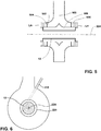
- FIG 5 and 6 illustrate some potential locations and orientations around the circumference of annular housing 202 where one or more flow diversion ports 216 can be located.
- the number, location, and orientation of flow diversion ports 216 can be combined in any desirable manner, and the combinations are not limited to what is illustrated.
- Each flow diversion port 216 illustrated in FIGS. 2 , 5, and 6 is configured to release flow with a center axis that avoids intersecting center axis 224 of steam outlet 220.
- center axis 230 of flow directed from flow diversion port 216 i.e., center axis 230 of flow where it exits flow diversion port 216) is angled by an angle ⁇ from center axis of steam outlet 220, wherein the angle can be any value greater than zero, as desired.
- the angle has a value such center axis 230 of flow directed from flow diversion port 216 intersects center axis 232 of main steam flow from main inlet port 212.
- the intersection can happen between main inlet port 212 and steam outlet 220, or it can happen on a far side of steam outlet 220 relative to main inlet port 212.
- an intersection of center axis of flow from flow diversion port 216 and center axis 232 of main steam flow from main inlet port 212 between main inlet port 212 and steam outlet 220 increases the diverting effect of flow from flow diversion port 216 on main steam flow from main inlet port 212.
- flow diversion port 216 can be angled so no line extending within a periphery of flow diversion port 216 parallel to center axis 230 of flow diversion port 216 intersects center axis 224 of steam outlet 220, as illustrated in FIG. 6 .
- flow diversion supply conduit 218 and flow diversion port 216 are located and oriented to face (or direct fluid) farther from the center of internal chamber 210 or the center of steam outlet 220, such that axis 230 of flow directed from flow diversion port 216 is off-center with the center of steam outlet 220 by at least a radius of steam outlet 220.
- flow from flow diversion port 216 is directed into the main steam flow entering internal chamber 210 from main inlet port 212.
- Aiming flow diversion inlet 216 more directly into the path of steam entering inlet 200 through main inlet port 212 has a greater impact in redirecting the flow circumferentially, which can allow reduction of the pressure and mass flow of diversion flow necessary to achieve a desired level of circumferential flow.
- Flow diversion port 216 can have a smaller area than main inlet port 212. A smaller area can facilitate higher pressure to create more impact where the fluid enters internal chamber 210 from flow diversion port 216.
- the fluid entering inlet 200 through flow diversion port 216 can also have less mass flow than steam entering main inlet port 212.
- steam can enter inlet 200 through main inlet port 212 at about X kg/s while fluid can enter flow diversion inlet 216 at about X/30 kg/s.
- steam can enter inlet 200 through main inlet port 212 at about 210 kg/s while fluid can enter flow diversion inlet 216 at about 7 kg/s.
- this embodiment is merely one example, and a great range of values can be desirable and implemented.
- the range of incidence of steam at steam outlet 220 can be reduced from plus or minus 40 degrees to plus or minus 15 degrees, or less.
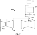
- FIG. 7 illustrates a turbine system 700 including a low pressure turbine 702, a high pressure turbine 704, and an intermediate pressure turbine 706, and a flow diversion supply conduit 707.
- the flow diversion supply conduit 707 is coupled to an external fluid supply 708 to deliver fluid of adequate pressure to the turbine inlet of low pressure turbine 702.
- External fluid supply 708 can have a supply fluid at a higher pressure than steam entering main inlet port 212.
- External fluid supply 708 need not have any fluid communication with other portions of turbine system 700, and can be controlled independently of the turbine system 700 to increases or decrease the flow diversion fluid delivered to the turbine inlet of low pressure turbine 702, without affecting operation of intermediate pressure turbine 706 or high pressure turbine 704.
- a controller 712 can be electrically coupled to external fluid supply 708 for automatic or electronic control of operation, and one or more valves 710 can be equipped in line with flow diversion supply conduit 707, again, to regulate the rate at which flow diversion fluid is delivered to the turbine inlet of low pressure turbine 702. Further, the flow diversion fluid can be shut off entirely either at valve 710 or at external fluid supply 708, without shutting off turbine system 700, which combined with the external components, provides for relatively easy and non-invasive maintenance.
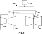
- FIG. 8 illustrates a turbine system 800 including a low pressure turbine 802, a high pressure turbine 804, an intermediate pressure turbine 806, and a flow diversion supply conduit 807.
- Flow diversion supply conduit 807 is coupled to intermediate pressure turbine 806 to supply steam through flow diversion supply conduit 807 to low pressure turbine 802.
- Flow diversion supply conduit 807 can be tied into an existing intermediate pressure turbine extraction point to reduce equipment and modification, or another point can be selected.
- a controller 812 can be electrically coupled to turbine system 800 for automatic or electronic control of operation, and one or more valves 810 can be equipped in line with flow diversion supply conduit 807, again, to regulate the rate at which flow diversion fluid is delivered to the turbine inlet of low pressure turbine 802.
- the flow diversion fluid can also be shut off entirely at valve 810, without shutting off turbine system 800, which combined with the external components, provides for relatively easy and non-invasive maintenance. Coupling to intermediate pressure turbine 806 might reduce its output and efficiency.
- the energy of the steam extracted from intermediate pressure turbine 806 can be sufficient to achieve the desired circumferential flow with relatively low energy loss, though, and the energy loss can be regained in excess from the improved, circumferential flow in the turbine inlet of low pressure turbine 802. A portion of the energy can also be regained from having a higher enthalpy fluid enter low pressure turbine 802.
- blades can be modified, or removed and replaced with differently designed blades.
- the rate and pressure of flow in flow diversion supply conduit 807 can scale with the power of intermediate pressure turbine 806. For example, when the turbine train, including low pressure turbine 802, high pressure turbine 804, and intermediate pressure turbine 806, runs at half capacity, steam extracted into fluid diversion supply conduit 807 will be reduced in proportion to the overall reduction of steam flow through intermediate pressure turbine 806.
- flow diversion supply conduit 807 can be coupled to high pressure turbine 804.
- the energy extracted from high pressure turbine 804 can be sufficient to achieve the desired circumferential flow, with relatively low energy loss that can be regained in excess from the improved, circumferential flow in the turbine inlet of low pressure turbine 802, and from reclaiming enthalpy (i.e., having a higher enthalpy fluid enter low pressure turbine 802).
- the shorter distance between intermediate pressure turbine 806 and low pressure turbine 802 than the distance between high pressure turbine 804 and low pressure turbine 802 can demand less equipment, space, and expense.
- high pressure turbine 804 extractions could be used to improve the inlet conditions of intermediate pressure turbine 806 inlet.
- the number of stages effected by the bypass increases, though, which may incur a performance penalty. There is a balance between extraction location and penalty incurred by the bypass.
- Teachings of the disclosure can be implemented as a new design or retrofitted to an existing turbine system.
- the outer casing 16 of turbine 10 ( FIG. 1 ) can be removed to access an existing turbine system.
- An existing low pressure turbine with an inlet such as the one described with reference to FIG. 2 , can be fitted with flow diversion port 216 by opening flow diversion port 216 through a housing of a turbine inlet and angling flow diversion port 216 so center axis 230 of flow from flow diversion port 216 avoids intersecting axis 224 of steam outlet 220 (in other words, off-center with steam outlet 220).
- Flow diversion supply conduit 707, 807 can be connected from the flow diversion fluid supply (e.g., intermediate pressure turbine 806, high pressure turbine 804, or external fluid supply 708) to flow diversion port 216.
- the flow diversion fluid supply can be opened for the connection, or the connection can be made at an existing connecting point.
- Blades 20 can be removed, modified, and replaced, or blades 20 can be removed and replaced with differently designed blades. Modifying a turbine inlet and a turbine system as described herein requires no additional parts internal to the turbine inlet, and minimal or no change to the inner and outer casings of the turbines.
- components described as being “coupled” to one another can be joined along one or more interfaces.
- these interfaces can include junctions between distinct components, and in other cases, these interfaces can include a solidly and/or integrally formed interconnection. That is, in some cases, components that are “coupled” to one another can be simultaneously formed to define a single continuous member.
- these coupled components can be formed as separate members and be subsequently joined through known processes (e.g., soldering, fastening, ultrasonic welding, bonding).
- electronic components described as being “coupled” can be linked via conventional hard-wired and/or wireless means such that these electronic components can communicate data with one another.
- spatially relative terms such as “inner,” “outer,” “beneath”, “below”, “lower”, “above”, “upper” and the like, may be used herein for ease of description to describe one element or feature's relationship to another element(s) or feature(s) as illustrated in the figures.
- Spatially relative terms may be intended to encompass different orientations of the device in use or operation in addition to the orientation depicted in the figures. For example, if the device in the figures is turned over, elements described as “below” or “beneath” other elements or features would then be oriented “above” the other elements or features.
- the example term “below” can encompass both an orientation of above and below.
- the device may be otherwise oriented (rotated 90 degrees or at other orientations) and the spatially relative descriptors used herein interpreted accordingly.
Landscapes
- Engineering & Computer Science (AREA)
- Mechanical Engineering (AREA)
- General Engineering & Computer Science (AREA)
- Turbine Rotor Nozzle Sealing (AREA)
Claims (9)
- System zum Bereitstellen eines Dampfstroms in die erste Stufe (L4) einer Turbine (10), umfassend einen Turbineneinlass (26, 200, 500), umfassend:• ein ringförmiges Gehäuse (202) mit einer äußeren umgebenden Umfangswand (204) und einem Paar axial beabstandeter Seitenwände (206, 208), wobei das ringförmige Gehäuse (202) eine innere Kammer (210) definiert;• eine Haupteinlassöffnung (212) zu dem ringförmigen Gehäuse (202), wobei die Haupteinlassöffnung (212) in Fluidverbindung mit der inneren Kammer (210) steht, um Dampf (24) in die innere Kammer (210) zu übertragen;• einen Dampfauslass (220) aus dem ringförmigen Gehäuse (202) und in Fluidverbindung mit der inneren Kammer (210) zum Leiten von Dampf aus der inneren Kammer (210) in die erste Stufe (L4) der Turbine (10), die stromabwärts des Turbineneinlasses fluidisch verbunden ist, wobei der Dampfauslass (220) eine Mittelachse (224) aufweist;• eine Stromablenkungsöffnung (216) zum ringförmigen Gehäuse (202), wobei der aus der Stromablenkungsöffnung (216) austretende Strom so gerichtet ist, dass eine Mittelachse (230) des Stroms ein Kreuzen mit der Mittelachse (224) des Dampfauslasses (220) vermeidet, und• eine Fluidzufuhrleitung, die die Stromablenkungsöffnung (216) mit einer Fluidzufuhr fluidtechnisch verbindet, wodurch Fluid von der Fluidzufuhr der inneren Kammer (210) zugeführt wird, wobei die Fluidzufuhr dazu konfiguriert ist, das Fluid der inneren Kammer (210) mit einem höheren Druck zuzuführen als Dampf, der von der Haupteinlassöffnung (212) in die innere Kammer (210) eintritt,dadurch gekennzeichnet, dass eine Mittelachse (230) eines Stroms, der von der Stromablenkungsöffnung (216) in die innere Kammer (210) eintritt, eine Mittelachse (232) eines Hauptdampfstroms, der von der Haupteinlassöffnung (212) in die innere Kammer (210) eintritt, kreuzt.
- System nach Anspruch 1, dadurch gekennzeichnet, dass die Stromablenkungsöffnung (216) eine Fläche aufweist und die Haupteinlassöffnung (212) eine Fläche aufweist und die Fläche der Stromablenkungsöffnung (216) kleiner als die Fläche der Haupteinlassöffnung (212) ist.
- System nach Anspruch 1 oder 2, dadurch gekennzeichnet, dass der Strom von der Stromablenkungsöffnung (216) in den Hauptdampf (24)-Strom gerichtet ist, der von der Haupteinlassöffnung (212) in die innere Kammer (210) eintritt.
- System nach einem der Ansprüche 1-3, dadurch gekennzeichnet, dass die Stromablenkungsöffnung (216) von der Mitte des Dampfauslasses (220) um einen Betrag versetzt ist, der mindestens so groß ist wie ein Radius des Dampfauslasses (220).
- System nach einem der Ansprüche 1-4, dadurch gekennzeichnet, dass das System ferner eine Stromablenkungszufuhrleitung (218, 707, 807) umfasst, wobei die Stromablenkungsöffnung (216) die Stromablenkungszufuhrleitung (218, 707, 807) mit der inneren Kammer (210) koppelt.
- System nach einem der Ansprüche 1-5, dadurch gekennzeichnet, dass der Dampfauslass (220) konzentrisch um eine Mittelachse (232) eines Rotors (12) angeordnet ist.
- Turbinensystem (700), umfassend:• ein System nach einem der Ansprüche 1-6, und• eine Turbine (10), die stromabwärts des Turbineneinlasses bereitgestellt und mit dem Dampfauslass (220) fluidisch verbunden ist.
- Turbinensystem (700) nach Anspruch 7, dadurch gekennzeichnet, dass die Stromablenkungsöffnung (216) eine Fläche aufweist, die kleiner als eine Fläche der Haupteinlassöffnung (212) ist.
- Turbinensystem (700) nach Anspruch 7 oder 8, dadurch gekennzeichnet, dass der Dampfauslass (220) eine Mittelachse (224) aufweist, wobei die Stromablenkungsöffnung (216) einen Umfang und eine Mittelachse (230) aufweist, und wobei die Stromablenkungsöffnung (216) so ausgerichtet ist, dass keine Linie, die sich durch den Umfang parallel zur Mittelachse (230) der Stromablenkungsöffnung (216) erstreckt, die Mittelachse (224) des Dampfauslasses (220) kreuzt.
Applications Claiming Priority (1)
| Application Number | Priority Date | Filing Date | Title |
|---|---|---|---|
| US15/270,139 US20180080324A1 (en) | 2016-09-20 | 2016-09-20 | Fluidically controlled steam turbine inlet scroll |
Publications (2)
| Publication Number | Publication Date |
|---|---|
| EP3296514A1 EP3296514A1 (de) | 2018-03-21 |
| EP3296514B1 true EP3296514B1 (de) | 2022-01-05 |
Family
ID=59923323
Family Applications (1)
| Application Number | Title | Priority Date | Filing Date |
|---|---|---|---|
| EP17192119.0A Active EP3296514B1 (de) | 2016-09-20 | 2017-09-20 | Fluidisch gesteuerte dampfturbineneinlassspirale |
Country Status (4)
| Country | Link |
|---|---|
| US (1) | US20180080324A1 (de) |
| EP (1) | EP3296514B1 (de) |
| JP (1) | JP7053196B2 (de) |
| CN (1) | CN107842397A (de) |
Families Citing this family (3)
| Publication number | Priority date | Publication date | Assignee | Title |
|---|---|---|---|---|
| PL3550133T3 (pl) | 2014-12-17 | 2022-08-01 | Pratt & Whitney Canada Corp. | Przewód wydechowy do silnika turbogazowego |
| DE102018219374A1 (de) * | 2018-11-13 | 2020-05-14 | Siemens Aktiengesellschaft | Dampfturbine und Verfahren zum Betreiben derselben |
| CN111520195B (zh) * | 2020-04-03 | 2022-05-10 | 东方电气集团东方汽轮机有限公司 | 一种汽轮机低压进汽室导流结构及其参数设计方法 |
Family Cites Families (22)
| Publication number | Priority date | Publication date | Assignee | Title |
|---|---|---|---|---|
| DE2213071B2 (de) * | 1972-03-17 | 1975-05-28 | Kraftwerk Union Ag, 4330 Muelheim | Leitschaufelloser Leitkanal zur Drallerzeugung vor dem ersten Laufschaufelkranz von Turbinen |
| FR2238382A5 (de) * | 1973-07-17 | 1975-02-14 | Rhone Poulenc Textile | |
| CH579212A5 (de) * | 1974-12-16 | 1976-08-31 | Bbc Brown Boveri & Cie | |
| US4416584A (en) * | 1980-08-28 | 1983-11-22 | Norquest Peter E | Ambient pressure water turbine |
| JPS6123601Y2 (de) * | 1980-10-22 | 1986-07-15 | ||
| CH654625A5 (de) * | 1981-11-30 | 1986-02-28 | Bbc Brown Boveri & Cie | Einlassgehaeuse einer dampfturbine. |
| DE3209506A1 (de) * | 1982-03-16 | 1983-09-22 | Kraftwerk Union AG, 4330 Mülheim | Axial beaufschlagte dampfturbine, insbesondere in zweiflutiger ausfuehrung |
| DE3617537A1 (de) * | 1986-05-24 | 1987-11-26 | Bbc Brown Boveri & Cie | Einstroemgehaeuse fuer eine stroemungsmaschine |
| JPH09158703A (ja) * | 1995-12-08 | 1997-06-17 | Toshiba Corp | 軸流タービン |
| US6287091B1 (en) * | 2000-05-10 | 2001-09-11 | General Motors Corporation | Turbocharger with nozzle ring coupling |
| US6402465B1 (en) * | 2001-03-15 | 2002-06-11 | Dresser-Rand Company | Ring valve for turbine flow control |
| EP1273762B1 (de) | 2001-07-02 | 2008-03-26 | Ansaldo Energia S.P.A. | Vorrichtung zur Regelung der ersten Stufe einer Dampfturbine |
| US6609881B2 (en) * | 2001-11-15 | 2003-08-26 | General Electric Company | Steam turbine inlet and methods of retrofitting |
| US8272832B2 (en) * | 2008-04-17 | 2012-09-25 | Honeywell International Inc. | Centrifugal compressor with surge control, and associated method |
| CN101307698A (zh) * | 2008-06-27 | 2008-11-19 | 西安交通大学 | 一种汽轮机的喷嘴配汽方法 |
| EP2157287A1 (de) * | 2008-08-22 | 2010-02-24 | ALSTOM Technology Ltd | Multifrequenzregelstufe für verbesserte Dämpfung der Anregungsfaktoren |
| GB2474344B (en) * | 2009-10-06 | 2016-01-27 | Cummins Ltd | Turbomachine |
| US8978389B2 (en) * | 2011-12-15 | 2015-03-17 | Siemens Energy, Inc. | Radial inflow gas turbine engine with advanced transition duct |
| CA2825849A1 (en) * | 2011-12-29 | 2013-07-04 | Elliott Company | Hot gas expander inlet casing assembly and method |
| US20140286758A1 (en) * | 2013-03-19 | 2014-09-25 | Abb Turbo Systems Ag | Nozzle ring with non-uniformly distributed airfoils and uniform throat area |
| JP6201548B2 (ja) * | 2013-09-09 | 2017-09-27 | 三菱日立パワーシステムズ株式会社 | 回転機械 |
| DE102013017145A1 (de) * | 2013-10-16 | 2014-07-24 | Daimler Ag | Turbine für einen Abgasturbolader |
-
2016
- 2016-09-20 US US15/270,139 patent/US20180080324A1/en not_active Abandoned
-
2017
- 2017-09-08 JP JP2017172577A patent/JP7053196B2/ja active Active
- 2017-09-20 CN CN201710857193.6A patent/CN107842397A/zh active Pending
- 2017-09-20 EP EP17192119.0A patent/EP3296514B1/de active Active
Non-Patent Citations (1)
| Title |
|---|
| None * |
Also Published As
| Publication number | Publication date |
|---|---|
| US20180080324A1 (en) | 2018-03-22 |
| JP2018066372A (ja) | 2018-04-26 |
| EP3296514A1 (de) | 2018-03-21 |
| JP7053196B2 (ja) | 2022-04-12 |
| CN107842397A (zh) | 2018-03-27 |
Similar Documents
| Publication | Publication Date | Title |
|---|---|---|
| JP5064494B2 (ja) | 主流が軸線方向に貫流可能な流体機械のためのリング状の流体管路 | |
| EP2009263B1 (de) | Tangentiale Anti-Wirbel-Luftzufuhr | |
| US8257015B2 (en) | Apparatus for cooling rotary components within a steam turbine | |
| US11293303B2 (en) | Connecting assembly for cooling the turbine of a turbine engine | |
| EP3296514B1 (de) | Fluidisch gesteuerte dampfturbineneinlassspirale | |
| CN112334665B (zh) | 用于制冷系统的混流式压缩机构造 | |
| US20140356143A1 (en) | Assembly for a fluid flow machine | |
| EP3059457B1 (de) | Verdichter und gasturbine | |
| US9664204B2 (en) | Assembly for a fluid flow machine | |
| EP3159486A1 (de) | Radraumdurchflussmischkammer | |
| US5927943A (en) | Inlet casing for a turbine | |
| EP3265653B1 (de) | Turbine für organische rankine-kreisläufe mit axialem eingang und ausgang | |
| CN111512031B (zh) | 涡轮机 | |
| US9587509B2 (en) | Assembly for a fluid flow machine | |
| CN114981521A (zh) | 用于涡轮机的模块 | |
| EP3557027B1 (de) | Übergangskanal, turbine und gasturbinenmotor | |
| EP4073353B1 (de) | Gehäusehalbschale für eine turbinenanlage und dampfturbine | |
| JP3686233B2 (ja) | 軸流タービン | |
| US10132195B2 (en) | Wheel space purge flow mixing chamber | |
| KR101900214B1 (ko) | 터빈 및 터보 과급기 | |
| EP2812548B1 (de) | Gasturbinenmotor | |
| US20130323009A1 (en) | Methods and apparatus for cooling rotary components within a steam turbine | |
| EP3798417A1 (de) | Mehrstromkühlkreislauf für eine fliesswegkomponente eines gasturbinentriebwerks | |
| RU2661915C1 (ru) | Впускной контур для одновального устройства | |
| US20220268161A1 (en) | Axial flow turbine |
Legal Events
| Date | Code | Title | Description |
|---|---|---|---|
| PUAI | Public reference made under article 153(3) epc to a published international application that has entered the european phase |
Free format text: ORIGINAL CODE: 0009012 |
|
| STAA | Information on the status of an ep patent application or granted ep patent |
Free format text: STATUS: THE APPLICATION HAS BEEN PUBLISHED |
|
| AK | Designated contracting states |
Kind code of ref document: A1 Designated state(s): AL AT BE BG CH CY CZ DE DK EE ES FI FR GB GR HR HU IE IS IT LI LT LU LV MC MK MT NL NO PL PT RO RS SE SI SK SM TR |
|
| AX | Request for extension of the european patent |
Extension state: BA ME |
|
| STAA | Information on the status of an ep patent application or granted ep patent |
Free format text: STATUS: REQUEST FOR EXAMINATION WAS MADE |
|
| 17P | Request for examination filed |
Effective date: 20180921 |
|
| RBV | Designated contracting states (corrected) |
Designated state(s): AL AT BE BG CH CY CZ DE DK EE ES FI FR GB GR HR HU IE IS IT LI LT LU LV MC MK MT NL NO PL PT RO RS SE SI SK SM TR |
|
| STAA | Information on the status of an ep patent application or granted ep patent |
Free format text: STATUS: EXAMINATION IS IN PROGRESS |
|
| 17Q | First examination report despatched |
Effective date: 20190719 |
|
| GRAP | Despatch of communication of intention to grant a patent |
Free format text: ORIGINAL CODE: EPIDOSNIGR1 |
|
| STAA | Information on the status of an ep patent application or granted ep patent |
Free format text: STATUS: GRANT OF PATENT IS INTENDED |
|
| INTG | Intention to grant announced |
Effective date: 20210531 |
|
| GRAJ | Information related to disapproval of communication of intention to grant by the applicant or resumption of examination proceedings by the epo deleted |
Free format text: ORIGINAL CODE: EPIDOSDIGR1 |
|
| STAA | Information on the status of an ep patent application or granted ep patent |
Free format text: STATUS: EXAMINATION IS IN PROGRESS |
|
| INTC | Intention to grant announced (deleted) | ||
| GRAP | Despatch of communication of intention to grant a patent |
Free format text: ORIGINAL CODE: EPIDOSNIGR1 |
|
| STAA | Information on the status of an ep patent application or granted ep patent |
Free format text: STATUS: GRANT OF PATENT IS INTENDED |
|
| GRAS | Grant fee paid |
Free format text: ORIGINAL CODE: EPIDOSNIGR3 |
|
| INTG | Intention to grant announced |
Effective date: 20211105 |
|
| GRAA | (expected) grant |
Free format text: ORIGINAL CODE: 0009210 |
|
| STAA | Information on the status of an ep patent application or granted ep patent |
Free format text: STATUS: THE PATENT HAS BEEN GRANTED |
|
| AK | Designated contracting states |
Kind code of ref document: B1 Designated state(s): AL AT BE BG CH CY CZ DE DK EE ES FI FR GB GR HR HU IE IS IT LI LT LU LV MC MK MT NL NO PL PT RO RS SE SI SK SM TR |
|
| REG | Reference to a national code |
Ref country code: GB Ref legal event code: FG4D |
|
| REG | Reference to a national code |
Ref country code: CH Ref legal event code: EP |
|
| REG | Reference to a national code |
Ref country code: AT Ref legal event code: REF Ref document number: 1460781 Country of ref document: AT Kind code of ref document: T Effective date: 20220115 |
|
| REG | Reference to a national code |
Ref country code: DE Ref legal event code: R096 Ref document number: 602017051796 Country of ref document: DE |
|
| REG | Reference to a national code |
Ref country code: IE Ref legal event code: FG4D |
|
| REG | Reference to a national code |
Ref country code: FI Ref legal event code: FGE |
|
| REG | Reference to a national code |
Ref country code: SE Ref legal event code: TRGR |
|
| REG | Reference to a national code |
Ref country code: LT Ref legal event code: MG9D |
|
| REG | Reference to a national code |
Ref country code: NL Ref legal event code: MP Effective date: 20220105 |
|
| REG | Reference to a national code |
Ref country code: AT Ref legal event code: MK05 Ref document number: 1460781 Country of ref document: AT Kind code of ref document: T Effective date: 20220105 |
|
| PG25 | Lapsed in a contracting state [announced via postgrant information from national office to epo] |
Ref country code: NL Free format text: LAPSE BECAUSE OF FAILURE TO SUBMIT A TRANSLATION OF THE DESCRIPTION OR TO PAY THE FEE WITHIN THE PRESCRIBED TIME-LIMIT Effective date: 20220105 |
|
| PG25 | Lapsed in a contracting state [announced via postgrant information from national office to epo] |
Ref country code: RS Free format text: LAPSE BECAUSE OF FAILURE TO SUBMIT A TRANSLATION OF THE DESCRIPTION OR TO PAY THE FEE WITHIN THE PRESCRIBED TIME-LIMIT Effective date: 20220105 Ref country code: PT Free format text: LAPSE BECAUSE OF FAILURE TO SUBMIT A TRANSLATION OF THE DESCRIPTION OR TO PAY THE FEE WITHIN THE PRESCRIBED TIME-LIMIT Effective date: 20220505 Ref country code: NO Free format text: LAPSE BECAUSE OF FAILURE TO SUBMIT A TRANSLATION OF THE DESCRIPTION OR TO PAY THE FEE WITHIN THE PRESCRIBED TIME-LIMIT Effective date: 20220405 Ref country code: LT Free format text: LAPSE BECAUSE OF FAILURE TO SUBMIT A TRANSLATION OF THE DESCRIPTION OR TO PAY THE FEE WITHIN THE PRESCRIBED TIME-LIMIT Effective date: 20220105 Ref country code: HR Free format text: LAPSE BECAUSE OF FAILURE TO SUBMIT A TRANSLATION OF THE DESCRIPTION OR TO PAY THE FEE WITHIN THE PRESCRIBED TIME-LIMIT Effective date: 20220105 Ref country code: ES Free format text: LAPSE BECAUSE OF FAILURE TO SUBMIT A TRANSLATION OF THE DESCRIPTION OR TO PAY THE FEE WITHIN THE PRESCRIBED TIME-LIMIT Effective date: 20220105 Ref country code: BG Free format text: LAPSE BECAUSE OF FAILURE TO SUBMIT A TRANSLATION OF THE DESCRIPTION OR TO PAY THE FEE WITHIN THE PRESCRIBED TIME-LIMIT Effective date: 20220405 |
|
| PG25 | Lapsed in a contracting state [announced via postgrant information from national office to epo] |
Ref country code: PL Free format text: LAPSE BECAUSE OF FAILURE TO SUBMIT A TRANSLATION OF THE DESCRIPTION OR TO PAY THE FEE WITHIN THE PRESCRIBED TIME-LIMIT Effective date: 20220105 Ref country code: LV Free format text: LAPSE BECAUSE OF FAILURE TO SUBMIT A TRANSLATION OF THE DESCRIPTION OR TO PAY THE FEE WITHIN THE PRESCRIBED TIME-LIMIT Effective date: 20220105 Ref country code: GR Free format text: LAPSE BECAUSE OF FAILURE TO SUBMIT A TRANSLATION OF THE DESCRIPTION OR TO PAY THE FEE WITHIN THE PRESCRIBED TIME-LIMIT Effective date: 20220406 Ref country code: AT Free format text: LAPSE BECAUSE OF FAILURE TO SUBMIT A TRANSLATION OF THE DESCRIPTION OR TO PAY THE FEE WITHIN THE PRESCRIBED TIME-LIMIT Effective date: 20220105 |
|
| PG25 | Lapsed in a contracting state [announced via postgrant information from national office to epo] |
Ref country code: IS Free format text: LAPSE BECAUSE OF FAILURE TO SUBMIT A TRANSLATION OF THE DESCRIPTION OR TO PAY THE FEE WITHIN THE PRESCRIBED TIME-LIMIT Effective date: 20220505 |
|
| REG | Reference to a national code |
Ref country code: DE Ref legal event code: R097 Ref document number: 602017051796 Country of ref document: DE |
|
| PG25 | Lapsed in a contracting state [announced via postgrant information from national office to epo] |
Ref country code: SM Free format text: LAPSE BECAUSE OF FAILURE TO SUBMIT A TRANSLATION OF THE DESCRIPTION OR TO PAY THE FEE WITHIN THE PRESCRIBED TIME-LIMIT Effective date: 20220105 Ref country code: SK Free format text: LAPSE BECAUSE OF FAILURE TO SUBMIT A TRANSLATION OF THE DESCRIPTION OR TO PAY THE FEE WITHIN THE PRESCRIBED TIME-LIMIT Effective date: 20220105 Ref country code: RO Free format text: LAPSE BECAUSE OF FAILURE TO SUBMIT A TRANSLATION OF THE DESCRIPTION OR TO PAY THE FEE WITHIN THE PRESCRIBED TIME-LIMIT Effective date: 20220105 Ref country code: EE Free format text: LAPSE BECAUSE OF FAILURE TO SUBMIT A TRANSLATION OF THE DESCRIPTION OR TO PAY THE FEE WITHIN THE PRESCRIBED TIME-LIMIT Effective date: 20220105 Ref country code: DK Free format text: LAPSE BECAUSE OF FAILURE TO SUBMIT A TRANSLATION OF THE DESCRIPTION OR TO PAY THE FEE WITHIN THE PRESCRIBED TIME-LIMIT Effective date: 20220105 Ref country code: CZ Free format text: LAPSE BECAUSE OF FAILURE TO SUBMIT A TRANSLATION OF THE DESCRIPTION OR TO PAY THE FEE WITHIN THE PRESCRIBED TIME-LIMIT Effective date: 20220105 |
|
| PLBE | No opposition filed within time limit |
Free format text: ORIGINAL CODE: 0009261 |
|
| STAA | Information on the status of an ep patent application or granted ep patent |
Free format text: STATUS: NO OPPOSITION FILED WITHIN TIME LIMIT |
|
| PG25 | Lapsed in a contracting state [announced via postgrant information from national office to epo] |
Ref country code: AL Free format text: LAPSE BECAUSE OF FAILURE TO SUBMIT A TRANSLATION OF THE DESCRIPTION OR TO PAY THE FEE WITHIN THE PRESCRIBED TIME-LIMIT Effective date: 20220105 |
|
| 26N | No opposition filed |
Effective date: 20221006 |
|
| PG25 | Lapsed in a contracting state [announced via postgrant information from national office to epo] |
Ref country code: SI Free format text: LAPSE BECAUSE OF FAILURE TO SUBMIT A TRANSLATION OF THE DESCRIPTION OR TO PAY THE FEE WITHIN THE PRESCRIBED TIME-LIMIT Effective date: 20220105 |
|
| REG | Reference to a national code |
Ref country code: DE Ref legal event code: R119 Ref document number: 602017051796 Country of ref document: DE |
|
| PG25 | Lapsed in a contracting state [announced via postgrant information from national office to epo] |
Ref country code: MC Free format text: LAPSE BECAUSE OF FAILURE TO SUBMIT A TRANSLATION OF THE DESCRIPTION OR TO PAY THE FEE WITHIN THE PRESCRIBED TIME-LIMIT Effective date: 20220105 |
|
| REG | Reference to a national code |
Ref country code: CH Ref legal event code: PL |
|
| REG | Reference to a national code |
Ref country code: BE Ref legal event code: MM Effective date: 20220930 |
|
| P01 | Opt-out of the competence of the unified patent court (upc) registered |
Effective date: 20230523 |
|
| PG25 | Lapsed in a contracting state [announced via postgrant information from national office to epo] |
Ref country code: LU Free format text: LAPSE BECAUSE OF NON-PAYMENT OF DUE FEES Effective date: 20220920 |
|
| PG25 | Lapsed in a contracting state [announced via postgrant information from national office to epo] |
Ref country code: LI Free format text: LAPSE BECAUSE OF NON-PAYMENT OF DUE FEES Effective date: 20220930 Ref country code: IT Free format text: LAPSE BECAUSE OF FAILURE TO SUBMIT A TRANSLATION OF THE DESCRIPTION OR TO PAY THE FEE WITHIN THE PRESCRIBED TIME-LIMIT Effective date: 20220105 Ref country code: IE Free format text: LAPSE BECAUSE OF NON-PAYMENT OF DUE FEES Effective date: 20220920 Ref country code: DE Free format text: LAPSE BECAUSE OF NON-PAYMENT OF DUE FEES Effective date: 20230401 Ref country code: CH Free format text: LAPSE BECAUSE OF NON-PAYMENT OF DUE FEES Effective date: 20220930 |
|
| PG25 | Lapsed in a contracting state [announced via postgrant information from national office to epo] |
Ref country code: BE Free format text: LAPSE BECAUSE OF NON-PAYMENT OF DUE FEES Effective date: 20220930 |
|
| PG25 | Lapsed in a contracting state [announced via postgrant information from national office to epo] |
Ref country code: HU Free format text: LAPSE BECAUSE OF FAILURE TO SUBMIT A TRANSLATION OF THE DESCRIPTION OR TO PAY THE FEE WITHIN THE PRESCRIBED TIME-LIMIT; INVALID AB INITIO Effective date: 20170920 |
|
| PG25 | Lapsed in a contracting state [announced via postgrant information from national office to epo] |
Ref country code: CY Free format text: LAPSE BECAUSE OF FAILURE TO SUBMIT A TRANSLATION OF THE DESCRIPTION OR TO PAY THE FEE WITHIN THE PRESCRIBED TIME-LIMIT Effective date: 20220105 |
|
| REG | Reference to a national code |
Ref country code: FI Ref legal event code: PCE Owner name: GENERAL ELECTRIC TECHNOLOGY GMBH |
|
| REG | Reference to a national code |
Ref country code: GB Ref legal event code: 732E Free format text: REGISTERED BETWEEN 20240502 AND 20240508 |
|
| PG25 | Lapsed in a contracting state [announced via postgrant information from national office to epo] |
Ref country code: MK Free format text: LAPSE BECAUSE OF FAILURE TO SUBMIT A TRANSLATION OF THE DESCRIPTION OR TO PAY THE FEE WITHIN THE PRESCRIBED TIME-LIMIT Effective date: 20220105 |
|
| PG25 | Lapsed in a contracting state [announced via postgrant information from national office to epo] |
Ref country code: MT Free format text: LAPSE BECAUSE OF FAILURE TO SUBMIT A TRANSLATION OF THE DESCRIPTION OR TO PAY THE FEE WITHIN THE PRESCRIBED TIME-LIMIT Effective date: 20220105 |
|
| REG | Reference to a national code |
Ref country code: FI Ref legal event code: PCE Owner name: ARABELLE TECHNOLOGIES |
|
| REG | Reference to a national code |
Ref country code: GB Ref legal event code: 732E Free format text: REGISTERED BETWEEN 20250213 AND 20250219 |
|
| REG | Reference to a national code |
Ref country code: GB Ref legal event code: 732E Free format text: REGISTERED BETWEEN 20250619 AND 20250625 |
|
| PGFP | Annual fee paid to national office [announced via postgrant information from national office to epo] |
Ref country code: FI Payment date: 20250820 Year of fee payment: 9 |
|
| PGFP | Annual fee paid to national office [announced via postgrant information from national office to epo] |
Ref country code: TR Payment date: 20250828 Year of fee payment: 9 |
|
| PGFP | Annual fee paid to national office [announced via postgrant information from national office to epo] |
Ref country code: GB Payment date: 20250822 Year of fee payment: 9 |
|
| PGFP | Annual fee paid to national office [announced via postgrant information from national office to epo] |
Ref country code: FR Payment date: 20250820 Year of fee payment: 9 |
|
| PGFP | Annual fee paid to national office [announced via postgrant information from national office to epo] |
Ref country code: SE Payment date: 20250820 Year of fee payment: 9 |
|
| REG | Reference to a national code |
Ref country code: FI Ref legal event code: PCE Owner name: ARABELLE SOLUTIONS FRANCE, FR |