EP3296540A1 - Moteur à turbine à gaz doté d'un système de réacteur à réducteur - Google Patents
Moteur à turbine à gaz doté d'un système de réacteur à réducteur Download PDFInfo
- Publication number
- EP3296540A1 EP3296540A1 EP16189699.8A EP16189699A EP3296540A1 EP 3296540 A1 EP3296540 A1 EP 3296540A1 EP 16189699 A EP16189699 A EP 16189699A EP 3296540 A1 EP3296540 A1 EP 3296540A1
- Authority
- EP
- European Patent Office
- Prior art keywords
- gas turbine
- shaft
- turbine engine
- gearbox
- torque
- Prior art date
- Legal status (The legal status is an assumption and is not a legal conclusion. Google has not performed a legal analysis and makes no representation as to the accuracy of the status listed.)
- Granted
Links
Images


Classifications
-
- F—MECHANICAL ENGINEERING; LIGHTING; HEATING; WEAPONS; BLASTING
- F01—MACHINES OR ENGINES IN GENERAL; ENGINE PLANTS IN GENERAL; STEAM ENGINES
- F01D—NON-POSITIVE DISPLACEMENT MACHINES OR ENGINES, e.g. STEAM TURBINES
- F01D21/00—Shutting-down of machines or engines, e.g. in emergency; Regulating, controlling, or safety means not otherwise provided for
- F01D21/04—Shutting-down of machines or engines, e.g. in emergency; Regulating, controlling, or safety means not otherwise provided for responsive to undesired position of rotor relative to stator or to breaking-off of a part of the rotor, e.g. indicating such position
-
- F—MECHANICAL ENGINEERING; LIGHTING; HEATING; WEAPONS; BLASTING
- F02—COMBUSTION ENGINES; HOT-GAS OR COMBUSTION-PRODUCT ENGINE PLANTS
- F02C—GAS-TURBINE PLANTS; AIR INTAKES FOR JET-PROPULSION PLANTS; CONTROLLING FUEL SUPPLY IN AIR-BREATHING JET-PROPULSION PLANTS
- F02C3/00—Gas-turbine plants characterised by the use of combustion products as the working fluid
- F02C3/04—Gas-turbine plants characterised by the use of combustion products as the working fluid having a turbine driving a compressor
- F02C3/107—Gas-turbine plants characterised by the use of combustion products as the working fluid having a turbine driving a compressor with two or more rotors connected by power transmission
-
- F—MECHANICAL ENGINEERING; LIGHTING; HEATING; WEAPONS; BLASTING
- F02—COMBUSTION ENGINES; HOT-GAS OR COMBUSTION-PRODUCT ENGINE PLANTS
- F02C—GAS-TURBINE PLANTS; AIR INTAKES FOR JET-PROPULSION PLANTS; CONTROLLING FUEL SUPPLY IN AIR-BREATHING JET-PROPULSION PLANTS
- F02C7/00—Features, components parts, details or accessories, not provided for in, or of interest apart form groups F02C1/00 - F02C6/00; Air intakes for jet-propulsion plants
- F02C7/36—Power transmission arrangements between the different shafts of the gas turbine plant, or between the gas-turbine plant and the power user
-
- F—MECHANICAL ENGINEERING; LIGHTING; HEATING; WEAPONS; BLASTING
- F02—COMBUSTION ENGINES; HOT-GAS OR COMBUSTION-PRODUCT ENGINE PLANTS
- F02K—JET-PROPULSION PLANTS
- F02K3/00—Plants including a gas turbine driving a compressor or a ducted fan
- F02K3/02—Plants including a gas turbine driving a compressor or a ducted fan in which part of the working fluid by-passes the turbine and combustion chamber
- F02K3/04—Plants including a gas turbine driving a compressor or a ducted fan in which part of the working fluid by-passes the turbine and combustion chamber the plant including ducted fans, i.e. fans with high volume, low pressure outputs, for augmenting the jet thrust, e.g. of double-flow type
- F02K3/06—Plants including a gas turbine driving a compressor or a ducted fan in which part of the working fluid by-passes the turbine and combustion chamber the plant including ducted fans, i.e. fans with high volume, low pressure outputs, for augmenting the jet thrust, e.g. of double-flow type with front fan
-
- F—MECHANICAL ENGINEERING; LIGHTING; HEATING; WEAPONS; BLASTING
- F05—INDEXING SCHEMES RELATING TO ENGINES OR PUMPS IN VARIOUS SUBCLASSES OF CLASSES F01-F04
- F05D—INDEXING SCHEME FOR ASPECTS RELATING TO NON-POSITIVE-DISPLACEMENT MACHINES OR ENGINES, GAS-TURBINES OR JET-PROPULSION PLANTS
- F05D2260/00—Function
- F05D2260/40—Transmission of power
- F05D2260/402—Transmission of power through friction drives
- F05D2260/4023—Transmission of power through friction drives through a friction clutch
-
- F—MECHANICAL ENGINEERING; LIGHTING; HEATING; WEAPONS; BLASTING
- F05—INDEXING SCHEMES RELATING TO ENGINES OR PUMPS IN VARIOUS SUBCLASSES OF CLASSES F01-F04
- F05D—INDEXING SCHEME FOR ASPECTS RELATING TO NON-POSITIVE-DISPLACEMENT MACHINES OR ENGINES, GAS-TURBINES OR JET-PROPULSION PLANTS
- F05D2260/00—Function
- F05D2260/40—Transmission of power
- F05D2260/403—Transmission of power through the shape of the drive components
- F05D2260/4031—Transmission of power through the shape of the drive components as in toothed gearing
-
- F—MECHANICAL ENGINEERING; LIGHTING; HEATING; WEAPONS; BLASTING
- F05—INDEXING SCHEMES RELATING TO ENGINES OR PUMPS IN VARIOUS SUBCLASSES OF CLASSES F01-F04
- F05D—INDEXING SCHEME FOR ASPECTS RELATING TO NON-POSITIVE-DISPLACEMENT MACHINES OR ENGINES, GAS-TURBINES OR JET-PROPULSION PLANTS
- F05D2270/00—Control
- F05D2270/01—Purpose of the control system
- F05D2270/02—Purpose of the control system to control rotational speed (n)
- F05D2270/021—Purpose of the control system to control rotational speed (n) to prevent overspeed
-
- F—MECHANICAL ENGINEERING; LIGHTING; HEATING; WEAPONS; BLASTING
- F05—INDEXING SCHEMES RELATING TO ENGINES OR PUMPS IN VARIOUS SUBCLASSES OF CLASSES F01-F04
- F05D—INDEXING SCHEME FOR ASPECTS RELATING TO NON-POSITIVE-DISPLACEMENT MACHINES OR ENGINES, GAS-TURBINES OR JET-PROPULSION PLANTS
- F05D2270/00—Control
- F05D2270/01—Purpose of the control system
- F05D2270/09—Purpose of the control system to cope with emergencies
-
- F—MECHANICAL ENGINEERING; LIGHTING; HEATING; WEAPONS; BLASTING
- F05—INDEXING SCHEMES RELATING TO ENGINES OR PUMPS IN VARIOUS SUBCLASSES OF CLASSES F01-F04
- F05D—INDEXING SCHEME FOR ASPECTS RELATING TO NON-POSITIVE-DISPLACEMENT MACHINES OR ENGINES, GAS-TURBINES OR JET-PROPULSION PLANTS
- F05D2270/00—Control
- F05D2270/40—Type of control system
- F05D2270/46—Type of control system redundant, i.e. failsafe operation
-
- F—MECHANICAL ENGINEERING; LIGHTING; HEATING; WEAPONS; BLASTING
- F16—ENGINEERING ELEMENTS AND UNITS; GENERAL MEASURES FOR PRODUCING AND MAINTAINING EFFECTIVE FUNCTIONING OF MACHINES OR INSTALLATIONS; THERMAL INSULATION IN GENERAL
- F16H—GEARING
- F16H2306/00—Shifting
- F16H2306/40—Shifting activities
- F16H2306/44—Removing torque from current gears
Definitions
- the invention relates to a gas turbine engine with a geared turbofan arrangement with the features of claim 1.
- Gas turbine engines with geared turbofan arrangements require some means to mitigate damages that might occur after a failure.
- a failure might involve the rotation prevention of at least one part of the drive train. Such a failure might be e.g. a shaft breaking, a rotor-casing contact or a bearing seizure.
- a gas turbine engine with a geared turbofan arrangement with a gearbox in a drive train driven by a turbine, a driving side (i.e. the output side) of the gearbox being driveably connected with a propulsive fan, with at least one form locking connection device in a drive train enabling a controlled disengagement of at least one engine part from the drive train in case of a mechanical failure of the gas turbine engine or a part thereof and at least one load stop for bearing an essentially axial load in case of the mechanical failure of the gas turbine or a part thereof.
- the least one form locking connection device is positioned in a torque carrying shaft or a torque carrying part of a shaft, in particular a torque bearing coupling with the gearbox.
- the at least one form locking connection device is positioned between the torque bearing coupling of the gearbox with a fan shaft and a torque carrier of the gearbox.
- the at least one form locking connection device is positioned in a non-torque carrying shaft, in particular a thrust shaft behind a fan catcher. These positions are especially suited for a controlled disengagement of the propulsive fan from the drive train.
- the form locking connection device can be e.g. a clutch or a spline connection for a controlled release of the rotating parts. It is possible that two different form locking connection devices can work together to release e.g. the fan shaft from the gearbox output (torque carrier) and the thrust shaft, such that it is no longer axially constrained or torsionally connected to the gearbox.
- the clutch connection can be released through a torque above a certain threshold value, a change in the direction of the torque, a hydraulic pressure and / or an electronic activation.
- At least one load stop is positioned between a torque carrying part of a shaft, in particular the torque bearing coupling of the gearbox to the fan shaft to engage a part moving part of the gas turbine engine after the mechanical failure.
- at least one load stop is designed for retaining the propulsive fan in the gas turbine engine and / or for directing loads away from the gearbox.
- the thrust shaft comprises and / or is contacting guiding means ("bumpers") to allow rotation under thrust shaft deflection occurring under a failure mode.
- an embodiment uses detection means for an overspeeding of a shaft, in particular the intermediate pressure shaft.
- the detection means are usually present in a gas turbine engine for other purposes.
- the signal regarding an overspeeding can be used to detect a shaft break and subsequently the engine will be shut down automatically.
- Another embodiment comprises a reference shaft for the detection of shaft break.
- the rotational speed of the reference shaft is measured. If there is a difference in the rotational speed of a driving shaft, this is an indication that a breakage has occurred.
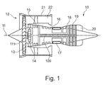
- a gas turbine engine is generally indicated at 10, having a principal and rotational axis 11.
- the engine 10 comprises, in axial flow series, an air intake 12, a propulsive fan 13 (could be more than one stage), a gearbox 14, an intermediate pressure compressor 15, a high-pressure compressor 16, a combustion equipment 17, a high-pressure turbine 18, an intermediate-pressure turbine 19 and an exhaust nozzle 20.
- a fan casing 21 generally surrounds the engine 10 and defines the intake 12.
- the gas turbine engine 10 works in the conventional manner so that air entering the intake 12 is accelerated by the propulsive fan 13 to produce two air flows: a first air flow into the intermediate pressure compressor 15 and a second air flow which passes through a bypass duct 22 to provide propulsive thrust.
- the intermediate pressure compressor 15 compresses the air flow directed into it before delivering that air to the high pressure compressor 16 where further compression takes place.
- the compressed air exhausted from the high-pressure compressor 16 is directed into the combustion equipment 17 where it is mixed with fuel and the mixture is combusted.
- the resultant hot combustion products then expand through, and thereby drive the high pressure turbine 18 and intermediate pressure turbine 19 before being exhausted through the nozzle 20 to provide additional propulsive thrust.
- An intermediate pressure shaft 109 also drives the propulsive fan 13 via the gearbox 14.
- the gearbox 14 is a reduction gearbox in that it gears down the rate of rotation of the propulsive fan 13 by comparison with the intermediate pressure compressor 15 and intermediate pressure turbine 19.
- the gearbox 14 is an epicyclic planetary gearbox having a static ring gear, rotating and orbiting planet gears supported by a planet carrier and a rotating sun gear 111.
- Fig. 1 has a specific shaft arrangement which is understood not to be limiting.
- the embodiments described in the following can also work with a 2- or 3-shaft arrangement.
- geared turbofan engines 10 are known in the art. With increasing power ratings and / or increasing diameters of the propulsive fans 13, the loads on the gas turbine engines 10 are increasing. Therefore, it seems advisable to introduce measures to counteract potential failure modes or extreme events such as e.g. a fan blade off, a core blade off, a bird strike, a mainline bearing seizure or a gearbox 14 seizure. Some of such failure modes will be described below
- the counter measures to the failures comprise at least one form locking connection device 61, 62 enabling a controlled disengagement of at least one engine part from the drive train.
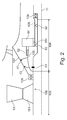
- the drive train comprises e.g. the shafts (e.g. a thrust shaft 104, Fig. 2 ) leading from the turbines 18, 19 to the compressors 15, 16, the gearbox 14 and the propulsive fan 13. Further details of the drive train in the embodiments will be shown below.
- the propulsive fan 13 is driven by the output of the gearbox 14 via a shaft 102, the shaft 102 being a part of the drive part assembly.
- the shaft 102 comprises several parts, in particular a fan shaft 103 and a thrust shaft 104. Furthermore, a torque bearing coupling 105 - also being a part of the shaft 102 - is connecting the shaft 102 with the gearbox 14 at the junction between the fan shaft 103 and the thrust shaft 104.
- the gearbox 14 is only shown schematically in Fig. 2 to 6 with a sun gear 111 around the thrust shaft 104.
- the thrust shaft 104 As a part of the shaft 102 does not carry torque, just bending moments and thrust loads. Under nominal operation thrust loads and bending moments are carried by the fan shaft 103, the thrust shaft 104, an intershaft bearing 106 eventually to a pylon (not shown in the figures) of the gas turbine engine 10.
- the drive train from gearbox 14 towards the front of the gas turbine engine 10 comprises the torque bearing coupling 105, the fan shaft 103 and the fan disk 101.
- the torque bearing coupling 105 can have a different shape than the one shown here.
- a front bearing cone 107 encloses in particular the gearbox 14 and the torque bearing coupling 105.
- the releasing (i.e. the opening) of the first and second from locking device connection 61, 62 e.g. a clutch and a spline connection
- locking device connection 61, 62 e.g. a clutch and a spline connection
- FIG. 2 In the embodiment shown in Fig. 2 , two form locking connection devices 61, 62 are shown.
- the first form locking connection device 61 is designed as a clutch to release, i.e. to open the connection under a defined load (i.e. torque). This leads to the intended disengagement of the rotating parts.
- a generally known spring loaded clutch, a ratchet clutch or a friction plate clutch can be used as a clutch.
- the second form locking connection device 62 is designed as a spline connection.
- the clutch 62 is released (e.g. a gearbox 14 seizure), or in the event that the thrust shaft 104 fails, the spline connection 61 releases under axial load, not torque.
- the clutch 61 releases due to high bending moments or the clutch 61 releases due to high torque or the spline 62 is released and the clutch 61 releases due to axial loads.
- the torque bearing coupling 105, the thrust shaft 104 and / or the front bearing cone 107 are deliberately disengaged by the form locking connection devices 61, 62 to allow a defined opening of the connection under a defined load. It should be noted that not all embodiments require to have the one clutches 61 and one spline connection 62.
- the gearbox 14 is only shown schematically in Fig. 2 with the sun gear 111 around the thrust shaft 104.
- the first load stop 41 comprises an angled structure (one arm pointing in axial direction backwards, one arm pointing radially inwards) mounted or integral with the front bearing cone 107. Radially inwards a matching structure (one arm pointing in axial direction backwards, one arm pointing radially inwards) is mounted or integral with the torque bearing coupling 105.
- first and second form locking connection devices 61, 62 are opened (i.e. due to a threshold exceeding torque), the torque bearing coupling 105 - together with the fan shaft 103 and the propulsive fan 13 - will have some radial and axial movement.
- the angled structure of the first load stop 41 controls the radial and axial movement of those parts because of a form-locking effect when the two parts of the angled structures 41 are moved together after the mechanical failure.
- the second load stop 42 also comprises an angled structure.
- the one part mounted or integral with the front bearing cone 107 has one arm pointing in the axial forward position, one arm pointing in the radial inward direction.
- the matching structure to this part is mounted or integral with the torque bearing coupling 105.
- This second load stop 42 can take an axial load during a windmilling situation after the propulsive fan 13 has been disengaged from the gearbox 14.
- the thrust shaft 104 is contacting guiding means 50 to allow rotation under thrust shaft deflection.
- the guiding means 50 are e.g. local protrusions or ring-like structures.
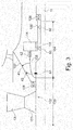
- FIG. 3 a part of a gas turbine engine 10 as depicted in Fig. 2 is shown. In principle, reference can be made to the respective description.
- the second form locking connection device 62 is a spline which is connected between the torque bearing coupling 105 and the torque carrier of the gearbox 14.
- the load stops 41, 42 operate as in the embodiment described in Fig. 2 .
- Fig. 3A the embodiment of Fig. 3 is shown in a disengaged position, i.e. the spline as form locking connection 62 is disengaged.
- the load stops 41, 42 are moved together.
- the gap in the thrust shaft 104 indicates the activation of the thrust shaft clutch or a thurst shaft 104 break scenario.
- the second form locking connection device 62 is also a spline.
- the spline connection is positioned at the connection of the torque bearing coupling 105 with the thrust shaft 104.
- a fan catcher 112 also schematically shown. In it extends from the front of the propulsive fan 13 to the intermediated pressure shaft 109.
- Fig. 4A the embodiment of Fig. 4 is shown in a disengaged position, i.e. the spline as form locking connection 62 is disengaged.
- an optional restrain device 113 connected to the front bearing cone is shown.
- the fan catcher 112 provides a secondary load path.
- the form locking connection devices 61, 62 should be sufficiently strong under a bird strike.
- the loads i.e. the threshold release loads of the form locking connection devices 61, 62
- the gas turbine engines 10 need to be able to run on partial power.
Landscapes
- Engineering & Computer Science (AREA)
- Mechanical Engineering (AREA)
- General Engineering & Computer Science (AREA)
- Chemical & Material Sciences (AREA)
- Combustion & Propulsion (AREA)
- Structures Of Non-Positive Displacement Pumps (AREA)
- Aviation & Aerospace Engineering (AREA)
- Retarders (AREA)
Priority Applications (2)
| Application Number | Priority Date | Filing Date | Title |
|---|---|---|---|
| EP16189699.8A EP3296540B1 (fr) | 2016-09-20 | 2016-09-20 | Moteur à turbine à gaz doté d'un système de réacteur à réducteur |
| US15/647,953 US10669949B2 (en) | 2016-09-20 | 2017-07-12 | Gas turbine engine with a geared turbofan arrangement |
Applications Claiming Priority (1)
| Application Number | Priority Date | Filing Date | Title |
|---|---|---|---|
| EP16189699.8A EP3296540B1 (fr) | 2016-09-20 | 2016-09-20 | Moteur à turbine à gaz doté d'un système de réacteur à réducteur |
Publications (2)
| Publication Number | Publication Date |
|---|---|
| EP3296540A1 true EP3296540A1 (fr) | 2018-03-21 |
| EP3296540B1 EP3296540B1 (fr) | 2019-01-23 |
Family
ID=57046979
Family Applications (1)
| Application Number | Title | Priority Date | Filing Date |
|---|---|---|---|
| EP16189699.8A Active EP3296540B1 (fr) | 2016-09-20 | 2016-09-20 | Moteur à turbine à gaz doté d'un système de réacteur à réducteur |
Country Status (2)
| Country | Link |
|---|---|
| US (1) | US10669949B2 (fr) |
| EP (1) | EP3296540B1 (fr) |
Cited By (2)
| Publication number | Priority date | Publication date | Assignee | Title |
|---|---|---|---|---|
| EP3415726A1 (fr) * | 2017-06-16 | 2018-12-19 | United Technologies Corporation | Turboréacteur à engrenages avec protection contre la survitesse |
| EP3798425A1 (fr) * | 2019-09-30 | 2021-03-31 | Rolls-Royce plc | Moteur de turbine à gaz |
Families Citing this family (4)
| Publication number | Priority date | Publication date | Assignee | Title |
|---|---|---|---|---|
| EP3296540B1 (fr) | 2016-09-20 | 2019-01-23 | Rolls-Royce Deutschland Ltd & Co KG | Moteur à turbine à gaz doté d'un système de réacteur à réducteur |
| EP3296525B1 (fr) * | 2016-09-20 | 2019-11-27 | Rolls-Royce Deutschland Ltd & Co KG | Moteur à turbine à gaz doté d'un agencement de turboréacteur à réducteur |
| US11434784B2 (en) | 2019-09-12 | 2022-09-06 | Pratt & Whitney Canada Corp. | Bearing preload using external gearbox reaction |
| GB202314412D0 (en) | 2023-09-20 | 2023-11-01 | Rolls Royce Plc | Shaft for a gas turbine engine |
Citations (4)
| Publication number | Priority date | Publication date | Assignee | Title |
|---|---|---|---|---|
| EP2415991A2 (fr) * | 2010-08-05 | 2012-02-08 | Rolls-Royce Corporation | Turbomachine |
| EP2884056A1 (fr) * | 2013-12-11 | 2015-06-17 | United Technologies Corporation | Systèmes et procédés impliquant de multiples chemins de couple pour des moteurs de turbines à gaz |
| FR3022890A1 (fr) * | 2014-06-25 | 2016-01-01 | Snecma | Turbomachine comportant un moyen de decouplage d'une soufflante |
| EP2998557A1 (fr) * | 2014-09-17 | 2016-03-23 | Airbus Operations, S.L. | Moteur hybride d'aéronef |
Family Cites Families (30)
| Publication number | Priority date | Publication date | Assignee | Title |
|---|---|---|---|---|
| US3997042A (en) | 1975-11-05 | 1976-12-14 | General Motors Corporation | Aircraft engine coupling |
| US4270408A (en) | 1978-10-13 | 1981-06-02 | General Motors Corporation | Gear drive for gas turbine engine |
| GB2080486B (en) | 1980-07-15 | 1984-02-15 | Rolls Royce | Shafts |
| US5533825A (en) | 1994-11-14 | 1996-07-09 | General Electric Company | Parabolically helical spline shaft coupling |
| FR2817912B1 (fr) | 2000-12-07 | 2003-01-17 | Hispano Suiza Sa | Reducteur reprenant les efforts axiaux generes par la soufflante d'un turboreacteur |
| US6428269B1 (en) | 2001-04-18 | 2002-08-06 | United Technologies Corporation | Turbine engine bearing support |
| US6783319B2 (en) | 2001-09-07 | 2004-08-31 | General Electric Co. | Method and apparatus for supporting rotor assemblies during unbalances |
| FR2841592B1 (fr) | 2002-06-27 | 2004-09-10 | Snecma Moteurs | Recentrage d'un rotor apres decouplage |
| GB0216312D0 (en) | 2002-07-12 | 2002-08-21 | Rolls Royce Plc | Frangible coupling |
| DE10309910A1 (de) | 2003-03-07 | 2004-09-16 | Rolls-Royce Deutschland Ltd & Co Kg | Abschaltsystem zur Vermeidung eines Überdrehzahlzustandes bei einem Wellenbruch |
| US7603844B2 (en) | 2005-10-19 | 2009-10-20 | General Electric Company | Gas turbine engine assembly and methods of assembling same |
| US7921634B2 (en) | 2006-10-31 | 2011-04-12 | General Electric Company | Turbofan engine assembly and method of assembling same |
| US7882693B2 (en) | 2006-11-29 | 2011-02-08 | General Electric Company | Turbofan engine assembly and method of assembling same |
| US7716914B2 (en) | 2006-12-21 | 2010-05-18 | General Electric Company | Turbofan engine assembly and method of assembling same |
| US8104289B2 (en) | 2007-10-09 | 2012-01-31 | United Technologies Corp. | Systems and methods involving multiple torque paths for gas turbine engines |
| US8245518B2 (en) | 2008-11-28 | 2012-08-21 | Pratt & Whitney Canada Corp. | Mid turbine frame system for gas turbine engine |
| US8191352B2 (en) | 2008-12-19 | 2012-06-05 | General Electric Company | Geared differential speed counter-rotatable low pressure turbine |
| US8517672B2 (en) | 2010-02-23 | 2013-08-27 | General Electric Company | Epicyclic gearbox |
| US9353690B2 (en) | 2010-06-21 | 2016-05-31 | Hamilton Sundstrand Corporation | Interface with mount features for precise alignment |
| GB2487551A (en) | 2011-01-26 | 2012-08-01 | Rolls Royce Plc | Coupling having a threaded interconnector to limit torque |
| EP2535528B1 (fr) | 2011-06-17 | 2021-04-28 | Raytheon Technologies Corporation | Support de palier de turbosoufflante |
| DE102011084360B4 (de) | 2011-10-12 | 2015-07-02 | Rolls-Royce Deutschland Ltd & Co Kg | Strömungsarbeitsmaschine |
| US9869249B2 (en) | 2012-01-31 | 2018-01-16 | United Technologies Corporation | Speed sensor probe location in gas turbine engine |
| WO2014151785A1 (fr) | 2013-03-15 | 2014-09-25 | United Technologies Corporation | Agencement paliers et boîtier de transmission de réacteur à double flux |
| US20160160875A1 (en) | 2013-08-26 | 2016-06-09 | United Technologies Corporation | Gas turbine engine with fan clearance control |
| GB201419859D0 (en) | 2014-11-07 | 2014-12-24 | Rolls Royce Plc | No title listed |
| GB201511606D0 (en) | 2015-07-02 | 2015-08-19 | Rolls Royce Plc | Drive shaft assembly |
| GB201516570D0 (en) | 2015-09-18 | 2015-11-04 | Rolls Royce Plc | A Shafting Arrangement |
| GB201516571D0 (en) | 2015-09-18 | 2015-11-04 | Rolls Royce Plc | A Coupling for a Geared Turbo Fan |
| EP3296540B1 (fr) | 2016-09-20 | 2019-01-23 | Rolls-Royce Deutschland Ltd & Co KG | Moteur à turbine à gaz doté d'un système de réacteur à réducteur |
-
2016
- 2016-09-20 EP EP16189699.8A patent/EP3296540B1/fr active Active
-
2017
- 2017-07-12 US US15/647,953 patent/US10669949B2/en active Active
Patent Citations (4)
| Publication number | Priority date | Publication date | Assignee | Title |
|---|---|---|---|---|
| EP2415991A2 (fr) * | 2010-08-05 | 2012-02-08 | Rolls-Royce Corporation | Turbomachine |
| EP2884056A1 (fr) * | 2013-12-11 | 2015-06-17 | United Technologies Corporation | Systèmes et procédés impliquant de multiples chemins de couple pour des moteurs de turbines à gaz |
| FR3022890A1 (fr) * | 2014-06-25 | 2016-01-01 | Snecma | Turbomachine comportant un moyen de decouplage d'une soufflante |
| EP2998557A1 (fr) * | 2014-09-17 | 2016-03-23 | Airbus Operations, S.L. | Moteur hybride d'aéronef |
Cited By (8)
| Publication number | Priority date | Publication date | Assignee | Title |
|---|---|---|---|---|
| EP3415726A1 (fr) * | 2017-06-16 | 2018-12-19 | United Technologies Corporation | Turboréacteur à engrenages avec protection contre la survitesse |
| US10612555B2 (en) | 2017-06-16 | 2020-04-07 | United Technologies Corporation | Geared turbofan with overspeed protection |
| EP3686399A1 (fr) * | 2017-06-16 | 2020-07-29 | United Technologies Corporation | Turboréacteur à engrenages avec protection contre la survitesse |
| US11255337B2 (en) | 2017-06-16 | 2022-02-22 | Raytheon Technologies Corporation | Geared turbofan with overspeed protection |
| EP4276295A3 (fr) * | 2017-06-16 | 2024-01-10 | RTX Corporation | Turboréacteur à engrenages avec protection contre la survitesse |
| US12385413B2 (en) | 2017-06-16 | 2025-08-12 | Rtx Corporation | Geared turbofan with overspeed protection |
| EP3798425A1 (fr) * | 2019-09-30 | 2021-03-31 | Rolls-Royce plc | Moteur de turbine à gaz |
| US11898456B2 (en) | 2019-09-30 | 2024-02-13 | Rolls-Royce Plc | Gas turbine engine |
Also Published As
| Publication number | Publication date |
|---|---|
| EP3296540B1 (fr) | 2019-01-23 |
| US10669949B2 (en) | 2020-06-02 |
| US20180080387A1 (en) | 2018-03-22 |
Similar Documents
| Publication | Publication Date | Title |
|---|---|---|
| US10669949B2 (en) | Gas turbine engine with a geared turbofan arrangement | |
| US10626925B2 (en) | Gas turbine engine with a geared turbofan arrangement | |
| US10954813B2 (en) | Planetary gearbox system and method for operating a planetary gearbox system | |
| US11391290B2 (en) | Turbomachine comprising a means of uncoupling a fan | |
| EP3361057B1 (fr) | Turbine ayant de faibles exigences de survitesse et procédé | |
| EP2553251B1 (fr) | Système de soufflante adaptative pour moteur à double flux à cycle variable | |
| US10753409B2 (en) | Mechanical clutch device and method for operating a mechanical clutch device | |
| US10830151B2 (en) | Gas turbine engine coupling arrangement | |
| US20190055991A1 (en) | Mechanical fuse device and method for operating a mechanical fuse device | |
| US6827548B2 (en) | Rotor assemblies for gas turbine engines | |
| US20170002869A1 (en) | Drive shaft assembly | |
| EP3396115A1 (fr) | Turbine à gaz | |
| EP3575550B1 (fr) | Moteur à turbine à gaz comportant un système d'arbre à sécurité intégrée et procédé correspondant | |
| EP3396144B1 (fr) | Moteur à turbine à gaz doté d'un agencement de turboréacteur à réducteur | |
| US10502144B2 (en) | Gas turbine engine with a geared turbofan arrangement | |
| GB2377731A (en) | Rotor shaft assembly for a gas turbine engine | |
| GB2579198A (en) | Shaft disconnection |
Legal Events
| Date | Code | Title | Description |
|---|---|---|---|
| STAA | Information on the status of an ep patent application or granted ep patent |
Free format text: STATUS: EXAMINATION IS IN PROGRESS |
|
| PUAI | Public reference made under article 153(3) epc to a published international application that has entered the european phase |
Free format text: ORIGINAL CODE: 0009012 |
|
| 17P | Request for examination filed |
Effective date: 20170614 |
|
| AK | Designated contracting states |
Kind code of ref document: A1 Designated state(s): AL AT BE BG CH CY CZ DE DK EE ES FI FR GB GR HR HU IE IS IT LI LT LU LV MC MK MT NL NO PL PT RO RS SE SI SK SM TR |
|
| AX | Request for extension of the european patent |
Extension state: BA ME |
|
| GRAP | Despatch of communication of intention to grant a patent |
Free format text: ORIGINAL CODE: EPIDOSNIGR1 |
|
| STAA | Information on the status of an ep patent application or granted ep patent |
Free format text: STATUS: GRANT OF PATENT IS INTENDED |
|
| INTG | Intention to grant announced |
Effective date: 20180425 |
|
| GRAS | Grant fee paid |
Free format text: ORIGINAL CODE: EPIDOSNIGR3 |
|
| GRAA | (expected) grant |
Free format text: ORIGINAL CODE: 0009210 |
|
| STAA | Information on the status of an ep patent application or granted ep patent |
Free format text: STATUS: THE PATENT HAS BEEN GRANTED |
|
| AK | Designated contracting states |
Kind code of ref document: B1 Designated state(s): AL AT BE BG CH CY CZ DE DK EE ES FI FR GB GR HR HU IE IS IT LI LT LU LV MC MK MT NL NO PL PT RO RS SE SI SK SM TR |
|
| REG | Reference to a national code |
Ref country code: GB Ref legal event code: FG4D |
|
| REG | Reference to a national code |
Ref country code: CH Ref legal event code: EP |
|
| REG | Reference to a national code |
Ref country code: AT Ref legal event code: REF Ref document number: 1091633 Country of ref document: AT Kind code of ref document: T Effective date: 20190215 |
|
| REG | Reference to a national code |
Ref country code: IE Ref legal event code: FG4D |
|
| REG | Reference to a national code |
Ref country code: DE Ref legal event code: R096 Ref document number: 602016009403 Country of ref document: DE |
|
| REG | Reference to a national code |
Ref country code: NL Ref legal event code: MP Effective date: 20190123 |
|
| PG25 | Lapsed in a contracting state [announced via postgrant information from national office to epo] |
Ref country code: NL Free format text: LAPSE BECAUSE OF FAILURE TO SUBMIT A TRANSLATION OF THE DESCRIPTION OR TO PAY THE FEE WITHIN THE PRESCRIBED TIME-LIMIT Effective date: 20190123 |
|
| PG25 | Lapsed in a contracting state [announced via postgrant information from national office to epo] |
Ref country code: PT Free format text: LAPSE BECAUSE OF FAILURE TO SUBMIT A TRANSLATION OF THE DESCRIPTION OR TO PAY THE FEE WITHIN THE PRESCRIBED TIME-LIMIT Effective date: 20190523 Ref country code: ES Free format text: LAPSE BECAUSE OF FAILURE TO SUBMIT A TRANSLATION OF THE DESCRIPTION OR TO PAY THE FEE WITHIN THE PRESCRIBED TIME-LIMIT Effective date: 20190123 Ref country code: LT Free format text: LAPSE BECAUSE OF FAILURE TO SUBMIT A TRANSLATION OF THE DESCRIPTION OR TO PAY THE FEE WITHIN THE PRESCRIBED TIME-LIMIT Effective date: 20190123 Ref country code: PL Free format text: LAPSE BECAUSE OF FAILURE TO SUBMIT A TRANSLATION OF THE DESCRIPTION OR TO PAY THE FEE WITHIN THE PRESCRIBED TIME-LIMIT Effective date: 20190123 Ref country code: NO Free format text: LAPSE BECAUSE OF FAILURE TO SUBMIT A TRANSLATION OF THE DESCRIPTION OR TO PAY THE FEE WITHIN THE PRESCRIBED TIME-LIMIT Effective date: 20190423 Ref country code: SE Free format text: LAPSE BECAUSE OF FAILURE TO SUBMIT A TRANSLATION OF THE DESCRIPTION OR TO PAY THE FEE WITHIN THE PRESCRIBED TIME-LIMIT Effective date: 20190123 Ref country code: FI Free format text: LAPSE BECAUSE OF FAILURE TO SUBMIT A TRANSLATION OF THE DESCRIPTION OR TO PAY THE FEE WITHIN THE PRESCRIBED TIME-LIMIT Effective date: 20190123 |
|
| REG | Reference to a national code |
Ref country code: AT Ref legal event code: MK05 Ref document number: 1091633 Country of ref document: AT Kind code of ref document: T Effective date: 20190123 |
|
| PG25 | Lapsed in a contracting state [announced via postgrant information from national office to epo] |
Ref country code: HR Free format text: LAPSE BECAUSE OF FAILURE TO SUBMIT A TRANSLATION OF THE DESCRIPTION OR TO PAY THE FEE WITHIN THE PRESCRIBED TIME-LIMIT Effective date: 20190123 Ref country code: GR Free format text: LAPSE BECAUSE OF FAILURE TO SUBMIT A TRANSLATION OF THE DESCRIPTION OR TO PAY THE FEE WITHIN THE PRESCRIBED TIME-LIMIT Effective date: 20190424 Ref country code: IS Free format text: LAPSE BECAUSE OF FAILURE TO SUBMIT A TRANSLATION OF THE DESCRIPTION OR TO PAY THE FEE WITHIN THE PRESCRIBED TIME-LIMIT Effective date: 20190523 Ref country code: BG Free format text: LAPSE BECAUSE OF FAILURE TO SUBMIT A TRANSLATION OF THE DESCRIPTION OR TO PAY THE FEE WITHIN THE PRESCRIBED TIME-LIMIT Effective date: 20190423 Ref country code: RS Free format text: LAPSE BECAUSE OF FAILURE TO SUBMIT A TRANSLATION OF THE DESCRIPTION OR TO PAY THE FEE WITHIN THE PRESCRIBED TIME-LIMIT Effective date: 20190123 Ref country code: LV Free format text: LAPSE BECAUSE OF FAILURE TO SUBMIT A TRANSLATION OF THE DESCRIPTION OR TO PAY THE FEE WITHIN THE PRESCRIBED TIME-LIMIT Effective date: 20190123 |
|
| REG | Reference to a national code |
Ref country code: DE Ref legal event code: R097 Ref document number: 602016009403 Country of ref document: DE |
|
| PG25 | Lapsed in a contracting state [announced via postgrant information from national office to epo] |
Ref country code: SK Free format text: LAPSE BECAUSE OF FAILURE TO SUBMIT A TRANSLATION OF THE DESCRIPTION OR TO PAY THE FEE WITHIN THE PRESCRIBED TIME-LIMIT Effective date: 20190123 Ref country code: RO Free format text: LAPSE BECAUSE OF FAILURE TO SUBMIT A TRANSLATION OF THE DESCRIPTION OR TO PAY THE FEE WITHIN THE PRESCRIBED TIME-LIMIT Effective date: 20190123 Ref country code: IT Free format text: LAPSE BECAUSE OF FAILURE TO SUBMIT A TRANSLATION OF THE DESCRIPTION OR TO PAY THE FEE WITHIN THE PRESCRIBED TIME-LIMIT Effective date: 20190123 Ref country code: AL Free format text: LAPSE BECAUSE OF FAILURE TO SUBMIT A TRANSLATION OF THE DESCRIPTION OR TO PAY THE FEE WITHIN THE PRESCRIBED TIME-LIMIT Effective date: 20190123 Ref country code: DK Free format text: LAPSE BECAUSE OF FAILURE TO SUBMIT A TRANSLATION OF THE DESCRIPTION OR TO PAY THE FEE WITHIN THE PRESCRIBED TIME-LIMIT Effective date: 20190123 Ref country code: EE Free format text: LAPSE BECAUSE OF FAILURE TO SUBMIT A TRANSLATION OF THE DESCRIPTION OR TO PAY THE FEE WITHIN THE PRESCRIBED TIME-LIMIT Effective date: 20190123 Ref country code: CZ Free format text: LAPSE BECAUSE OF FAILURE TO SUBMIT A TRANSLATION OF THE DESCRIPTION OR TO PAY THE FEE WITHIN THE PRESCRIBED TIME-LIMIT Effective date: 20190123 |
|
| PG25 | Lapsed in a contracting state [announced via postgrant information from national office to epo] |
Ref country code: SM Free format text: LAPSE BECAUSE OF FAILURE TO SUBMIT A TRANSLATION OF THE DESCRIPTION OR TO PAY THE FEE WITHIN THE PRESCRIBED TIME-LIMIT Effective date: 20190123 |
|
| PLBE | No opposition filed within time limit |
Free format text: ORIGINAL CODE: 0009261 |
|
| STAA | Information on the status of an ep patent application or granted ep patent |
Free format text: STATUS: NO OPPOSITION FILED WITHIN TIME LIMIT |
|
| PG25 | Lapsed in a contracting state [announced via postgrant information from national office to epo] |
Ref country code: AT Free format text: LAPSE BECAUSE OF FAILURE TO SUBMIT A TRANSLATION OF THE DESCRIPTION OR TO PAY THE FEE WITHIN THE PRESCRIBED TIME-LIMIT Effective date: 20190123 |
|
| 26N | No opposition filed |
Effective date: 20191024 |
|
| PG25 | Lapsed in a contracting state [announced via postgrant information from national office to epo] |
Ref country code: SI Free format text: LAPSE BECAUSE OF FAILURE TO SUBMIT A TRANSLATION OF THE DESCRIPTION OR TO PAY THE FEE WITHIN THE PRESCRIBED TIME-LIMIT Effective date: 20190123 |
|
| PG25 | Lapsed in a contracting state [announced via postgrant information from national office to epo] |
Ref country code: TR Free format text: LAPSE BECAUSE OF FAILURE TO SUBMIT A TRANSLATION OF THE DESCRIPTION OR TO PAY THE FEE WITHIN THE PRESCRIBED TIME-LIMIT Effective date: 20190123 |
|
| PG25 | Lapsed in a contracting state [announced via postgrant information from national office to epo] |
Ref country code: MC Free format text: LAPSE BECAUSE OF FAILURE TO SUBMIT A TRANSLATION OF THE DESCRIPTION OR TO PAY THE FEE WITHIN THE PRESCRIBED TIME-LIMIT Effective date: 20190123 |
|
| REG | Reference to a national code |
Ref country code: CH Ref legal event code: PL |
|
| PG25 | Lapsed in a contracting state [announced via postgrant information from national office to epo] |
Ref country code: LU Free format text: LAPSE BECAUSE OF NON-PAYMENT OF DUE FEES Effective date: 20190920 Ref country code: IE Free format text: LAPSE BECAUSE OF NON-PAYMENT OF DUE FEES Effective date: 20190920 Ref country code: LI Free format text: LAPSE BECAUSE OF NON-PAYMENT OF DUE FEES Effective date: 20190930 Ref country code: CH Free format text: LAPSE BECAUSE OF NON-PAYMENT OF DUE FEES Effective date: 20190930 |
|
| REG | Reference to a national code |
Ref country code: BE Ref legal event code: MM Effective date: 20190930 |
|
| PG25 | Lapsed in a contracting state [announced via postgrant information from national office to epo] |
Ref country code: BE Free format text: LAPSE BECAUSE OF NON-PAYMENT OF DUE FEES Effective date: 20190930 |
|
| GBPC | Gb: european patent ceased through non-payment of renewal fee |
Effective date: 20200920 |
|
| PG25 | Lapsed in a contracting state [announced via postgrant information from national office to epo] |
Ref country code: CY Free format text: LAPSE BECAUSE OF FAILURE TO SUBMIT A TRANSLATION OF THE DESCRIPTION OR TO PAY THE FEE WITHIN THE PRESCRIBED TIME-LIMIT Effective date: 20190123 |
|
| PG25 | Lapsed in a contracting state [announced via postgrant information from national office to epo] |
Ref country code: MT Free format text: LAPSE BECAUSE OF FAILURE TO SUBMIT A TRANSLATION OF THE DESCRIPTION OR TO PAY THE FEE WITHIN THE PRESCRIBED TIME-LIMIT Effective date: 20190123 Ref country code: HU Free format text: LAPSE BECAUSE OF FAILURE TO SUBMIT A TRANSLATION OF THE DESCRIPTION OR TO PAY THE FEE WITHIN THE PRESCRIBED TIME-LIMIT; INVALID AB INITIO Effective date: 20160920 |
|
| PG25 | Lapsed in a contracting state [announced via postgrant information from national office to epo] |
Ref country code: GB Free format text: LAPSE BECAUSE OF NON-PAYMENT OF DUE FEES Effective date: 20200920 |
|
| PG25 | Lapsed in a contracting state [announced via postgrant information from national office to epo] |
Ref country code: MK Free format text: LAPSE BECAUSE OF FAILURE TO SUBMIT A TRANSLATION OF THE DESCRIPTION OR TO PAY THE FEE WITHIN THE PRESCRIBED TIME-LIMIT Effective date: 20190123 |
|
| P01 | Opt-out of the competence of the unified patent court (upc) registered |
Effective date: 20230528 |
|
| PGFP | Annual fee paid to national office [announced via postgrant information from national office to epo] |
Ref country code: DE Payment date: 20250926 Year of fee payment: 10 |
|
| PGFP | Annual fee paid to national office [announced via postgrant information from national office to epo] |
Ref country code: FR Payment date: 20250925 Year of fee payment: 10 |