EP3296542B1 - Geteiltes verdichterturbinentriebwerk - Google Patents
Geteiltes verdichterturbinentriebwerk Download PDFInfo
- Publication number
- EP3296542B1 EP3296542B1 EP17191922.8A EP17191922A EP3296542B1 EP 3296542 B1 EP3296542 B1 EP 3296542B1 EP 17191922 A EP17191922 A EP 17191922A EP 3296542 B1 EP3296542 B1 EP 3296542B1
- Authority
- EP
- European Patent Office
- Prior art keywords
- compressor
- turbine
- turbine engine
- engine
- silicon carbide
- Prior art date
- Legal status (The legal status is an assumption and is not a legal conclusion. Google has not performed a legal analysis and makes no representation as to the accuracy of the status listed.)
- Active
Links
Images
Classifications
-
- F—MECHANICAL ENGINEERING; LIGHTING; HEATING; WEAPONS; BLASTING
- F02—COMBUSTION ENGINES; HOT-GAS OR COMBUSTION-PRODUCT ENGINE PLANTS
- F02C—GAS-TURBINE PLANTS; AIR INTAKES FOR JET-PROPULSION PLANTS; CONTROLLING FUEL SUPPLY IN AIR-BREATHING JET-PROPULSION PLANTS
- F02C3/00—Gas-turbine plants characterised by the use of combustion products as the working fluid
- F02C3/04—Gas-turbine plants characterised by the use of combustion products as the working fluid having a turbine driving a compressor
- F02C3/107—Gas-turbine plants characterised by the use of combustion products as the working fluid having a turbine driving a compressor with two or more rotors connected by power transmission
-
- F—MECHANICAL ENGINEERING; LIGHTING; HEATING; WEAPONS; BLASTING
- F02—COMBUSTION ENGINES; HOT-GAS OR COMBUSTION-PRODUCT ENGINE PLANTS
- F02C—GAS-TURBINE PLANTS; AIR INTAKES FOR JET-PROPULSION PLANTS; CONTROLLING FUEL SUPPLY IN AIR-BREATHING JET-PROPULSION PLANTS
- F02C3/00—Gas-turbine plants characterised by the use of combustion products as the working fluid
- F02C3/14—Gas-turbine plants characterised by the use of combustion products as the working fluid characterised by the arrangement of the combustion chamber in the plant
- F02C3/145—Gas-turbine plants characterised by the use of combustion products as the working fluid characterised by the arrangement of the combustion chamber in the plant the combustion chamber being in the reverse flow-type
-
- F—MECHANICAL ENGINEERING; LIGHTING; HEATING; WEAPONS; BLASTING
- F02—COMBUSTION ENGINES; HOT-GAS OR COMBUSTION-PRODUCT ENGINE PLANTS
- F02C—GAS-TURBINE PLANTS; AIR INTAKES FOR JET-PROPULSION PLANTS; CONTROLLING FUEL SUPPLY IN AIR-BREATHING JET-PROPULSION PLANTS
- F02C7/00—Features, components parts, details or accessories, not provided for in, or of interest apart form groups F02C1/00 - F02C6/00; Air intakes for jet-propulsion plants
- F02C7/04—Air intakes for gas-turbine plants or jet-propulsion plants
-
- F—MECHANICAL ENGINEERING; LIGHTING; HEATING; WEAPONS; BLASTING
- F05—INDEXING SCHEMES RELATING TO ENGINES OR PUMPS IN VARIOUS SUBCLASSES OF CLASSES F01-F04
- F05D—INDEXING SCHEME FOR ASPECTS RELATING TO NON-POSITIVE-DISPLACEMENT MACHINES OR ENGINES, GAS-TURBINES OR JET-PROPULSION PLANTS
- F05D2240/00—Components
- F05D2240/40—Use of a multiplicity of similar components
-
- F—MECHANICAL ENGINEERING; LIGHTING; HEATING; WEAPONS; BLASTING
- F05—INDEXING SCHEMES RELATING TO ENGINES OR PUMPS IN VARIOUS SUBCLASSES OF CLASSES F01-F04
- F05D—INDEXING SCHEME FOR ASPECTS RELATING TO NON-POSITIVE-DISPLACEMENT MACHINES OR ENGINES, GAS-TURBINES OR JET-PROPULSION PLANTS
- F05D2250/00—Geometry
- F05D2250/30—Arrangement of components
Definitions
- the present disclosure relates generally to turbine engines, and more specifically to a split compressor turbine engine.
- Turbine engines generally compress air in a compressor section, and provide the compressed air to a combustor.
- the compressed air is mixed with a fuel, and ignited within the combustor.
- the resultant combustion products are passed to a turbine section, and are expanded across the turbine section.
- the expansion of the combustion products drives rotation of the turbine section.
- the turbine section is connected to the compressor section via one or more shafts, and the rotation of the turbine section, in turn, drives rotation of the compressor section.
- the compressor section and the turbine section each include multiple compressors and turbines, respectively.
- the first compressor referred to as a low pressure compressor, compresses ambient air, and provides the compressed air to the second compressor, referred to as the high pressure compressor.
- This arrangement is referred to as the compressors being in series, and provides compressed air to the combustor section from a single output source in the compressor section.
- EP 2 551 485 A2 discloses a prior art gas turbine engine with an aft core driven fan section.
- the invention provides a turbine engine as recited in claim 1.
- a fluid inlet of the first compressor and a fluid inlet of the second compressor are approximately equal sized, such that fluid flow into each of the first compressor and the second compressor is approximately equal.
- At least one of the first turbine and the second turbine is a single stage turbine.
- each of the first turbine and the second turbine is a single stage turbine.
- first compressor and the first turbine are connected to a first spool, and wherein the second compressor and the second turbine are connected to a second spool.
- the first spool and the second spool are collinear.
- the first compressor, the second compressor, the first turbine and the second turbine are connected to a single spool.
- At least one of the first compressor and the second compressor is a direct drive compressor.
- the first compressor and the second compressor are counter-rotating compressors.
- the first compressor and the second compressor are co-rotating.
- the invention also provides a method for driving a turbine engine as recited in claim 11.
- Another example of any of the above described methods for driving a turbine engine further includes driving rotation of the first compressor via a shaft connecting the first compressor to the first turbine, and driving rotation of the second compressor via a shaft connecting the second compressor to the second turbine.
- Another example of any of the above described methods for driving a turbine engine further includes driving rotation of the first compressor and the second compressor via a shaft connecting the first compressor and the second compressor to the first turbine and the second turbine.
- each of the first turbine and the second turbine are single stage turbines.
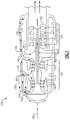
- FIG. 1 schematically illustrates an exemplary split compressor turbine engine architecture 100.
- the engine includes a pair of split compressors 112, 114 within a compressor section 110.
- the compressors 112, 114 share an inlet 116, and operate in fluid parallel, with the compressed air output being merged into a single compressed airflow 122 downstream of both compressors 112, 114.
- the inlet 116 draws ambient air from a surrounding atmosphere through a first inlet 102 on a forward end of the engine 100 and through a second inlet 104, on a radially outward surface of the engine 100.
- Airflow into the engine follows flowpath 120, and branches into the first inlet 102 along a first branch 124 and into the second inlet 104 along a second branch 126.
- the first and second branch 124, 126 merge at the compressor section 110 inlet 116, and the flow is then split again between inlets of the first compressor 112 and the second compressor 114.
- the split is approximately 50%, with each compressor 112, 114 receiving approximately the same volume of air along its respective flowpath as the other compressor 112, 114.
- Such an example can be achieved by providing each of the compressors 112, 114 approximately equal sized inlets, thereby ensure that an approximately equal volume of air will enter the compressors 112, 114.
- the compressors can be sized such that different volumes of air are received at their inlets, or a controlled or passive metering device can be incorporated at the inlet 116.
- Each compressor 112, 114 includes multiple compressor stages 118 that sequentially compress the air resulting in a higher pressure at the compressor outlet than at the compressor inlet 116.
- Each stage includes a compressor rotor and a corresponding compressor stator, with the rotors being shaped to drive air along the compressor as the rotors rotate.
- the compressor rotors are constructed of lightweight, high strength materials, such as a lightweight high strength ceramic material.
- the light weight high strength ceramic material is a silicon based structural material, such as silicon nitride, silicon carbide, silicon carbide reinforced ceramic composite, or carbon fiber reinforced silicon carbide composite.
- the compressed airflow 122 is passed to a reverse flow combustor 130, where the compressed air is mixed with a fuel and ignited according to known combustor techniques.
- the resultant combustion products are passed along a combustion product flowpath 140 into a turbine section 150.
- each of the single stage turbines 152, 154 includes a single rotor 151, and a single stator vane 153.
- either or both of the turbines 152, 154 within the turbine section 150 can include multiple turbine stages, instead of the illustrated single stage turbines 152, 154.
- Each rotor 151 is connected to a corresponding shaft 160, 170.
- the shafts 160, 170 are alternately referred to as spools.
- Each shaft 160, 170 connects the turbine rotor 151 to a corresponding one of the compressors 112, 114, and drives the rotation of the corresponding compressor 112, 114.
- the shafts 160, 170 are collinear, with the shaft 160 that is connected to the forward turbine 154 being radially outward of the shaft 170 that is connected to the aft turbine 152. While illustrated in Figure 1 utilizing direct drive connections to the shafts 160, 170, one of skill in the art could adapt the engine architecture 100 to utilize a geared connection, and drive one or both of the compressors 112, 114 via a geared connection.
- the turbines 152, 154 are sized such that rotation of the forward turbine 154, and rotation of the aft turbine 152, drive rotation of their corresponding compressors 112, 114 at the same, or approximately the same, speed at any given time.
- each of the compressors 112, 114 are driven to rotate in the same direction about an engine centerline axis, and are referred to as co-rotating compressors 112, 114.
- the compressors 112, 114 rotate in opposite directions about the centerline axis, and are referred to as counter-rotating compressors 112, 114.
- the turbine 152, 154 corresponding to a given compressor 112, 114 rotates in the same direction as the compressor 112, 114.
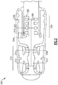
- Figure 2 schematically illustrates an alternate configuration split compressor turbine engine architecture 200.
- the architecture 200 includes two compressors 212, 214 arranged in parallel with an inlet flow to a compressor section 210 being split between the compressors 212, 214.
- the output of the compressor section 210 is provided to a reverse flow combustor 230, where the compressed air from the compressor section 210 is mixed with a fuel and ignited.
- the resultant combustion products are provided from the reverse flow combustor 230 to a turbine section 250 including a first turbine 254 and a second turbine 252.
- Each of the turbines 252, 254 includes a single stage having a stator 253 and a rotor 251. In alternative examples, the turbines 252, 254 can include multiple stages and operate in a similar fashion.
- Each of the turbines 252, 254 is connected to a single shaft 260.
- the shaft 260 is, in turn, connected to both of the compressors 212, 214 in either a direct drive (as illustrated) or a geared connection.
- the shaft 260 translates rotation from the turbines 252, 254 to the compressors 212, 214, thereby allowing the turbines 252, 254 to drive rotation of the compressors 212, 214.
- the engine architecture 200 of Figure 2 operates, and is configured, in fundamentally the same manner as the engine architecture of Figure 1 .
- One of skill in the art, having the benefit of this disclosure will understand the necessary adjustments required to configure the engine architecture for a single shaft, as opposed to the two shaft example described above in greater detail.
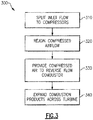
- Figure 3 illustrates a method 300 for operating a split compressor turbine engine, such as the engine architectures 100, 200 of Figures 1 and 2 .
- a split compressor turbine engine such as the engine architectures 100, 200 of Figures 1 and 2 .
- an airflow is provided to a split inlet, and is divided between two parallel operating compressors within a compressor section in a "Split Inlet Flow to Compressors" step 310.
- the compressors operate in parallel to compress the air, and provide an output of compressed air.
- the compressed air output from each compressor is rejoined into a single compressed airflow in a "Rejoin Compressed Airflow" step 320.
- the rejoined compressed air is provided to a reverse flow combustor and mixed with a fuel in the reverse flow combustor in a "Provide Compressed Air to Reverse Flow Combustor" step 330.
- the fuel/air mixture is ignited and the resultant combustion products are expelled from the reverse flow combustor according to known reverse flow combustor techniques.
- the resultant combustion products are provided to a turbine section and expanded across multiple turbines within the turbine section in an "Expand Combustion Products Across Turbine” step 340.
- the expansion of the combustion products drives the turbines to rotate, and the rotation of the turbines is utilized to drive rotation of at least one corresponding compressor via a shaft connection.
Landscapes
- Engineering & Computer Science (AREA)
- Chemical & Material Sciences (AREA)
- Combustion & Propulsion (AREA)
- Mechanical Engineering (AREA)
- General Engineering & Computer Science (AREA)
- Structures Of Non-Positive Displacement Pumps (AREA)
Claims (15)
- Turbinentriebwerk (100; 200), umfassend:einen ersten Verdichter (112; 212) und einen zweiten Verdichter (114; 214), der fluidisch parallel zu dem ersten Verdichter (112; 212) ist, wobei zumindest einer von dem ersten Verdichter (112; 212) und dem zweiten Verdichter (114; 214) aus mehreren Rotoren besteht, wobei jeder der Rotoren aus einer leichtgewichtigen Keramik mit hoher Stärke hergestellt ist;eine Rückflussbrennkammer (130; 230), die fluidisch mit dem ersten Verdichter (112; 212) und dem zweiten Verdichter (114; 214) verbunden ist; undeine erste Turbine (152; 252) und eine zweite Turbine (154; 254), die fluidisch in Reihe und fluidisch mit einer Ausgabe der Rückflussbrennkammer (130; 230) verbunden sind,
dadurch gekennzeichnet, dass:die leichtgewichtige Keramik mit hoher Stärke Siliziumnitrid, Siliziumkarbid, mit Siliziumkarbidfaser verstärkter Keramikverbundstoff oder mit Kohlefaser verstärkter Siliziumkarbidverbundstoff ist; undder erste und zweite Verdichter (112, 114; 212, 214) einen Fluideinlass (116) teilen. - Turbinentriebwerk nach Anspruch 1, wobei ein Fluideinlass des ersten Verdichters (112; 212) und ein Fluideinlass des zweiten Verdichters (114; 214) ungefähr gleich größenbemessen sind, sodass Fluidfluss in jeden von dem ersten Verdichter (112; 212) und dem zweiten Verdichter (114; 214) ungefähr gleich sind.
- Turbinentriebwerk nach Anspruch 1 oder 2, wobei zumindest eine von der ersten Turbine (152; 252) und der zweiten Turbine (154; 254) eine einstufige Turbine ist.
- Turbinentriebwerk nach einem vorhergehenden Anspruch, wobei der erste Verdichter (112) und die erste Turbine (152) mit einer ersten Spule (170) verbunden sind und der zweite Verdichter (114) und die zweite Turbine (154) mit einer zweiten Spule (160) verbunden sind.
- Turbinentriebwerk nach Anspruch 4, wobei die erste Spule (170) und die zweite Spule (160) kollinear sind.
- Turbinentriebwerk nach einem vorhergehenden Anspruch, wobei der erste Verdichter (112) und der zweite Verdichter (114) gegenläufig rotierende Verdichter sind.
- Turbinentriebwerk nach einem der Ansprüche 1 bis 3, wobei der erste Verdichter (212), der zweite Verdichter (214), die erste Turbine (252) und die zweite Turbine (254) mit einer einzelnen Spule (260) verbunden sind.
- Turbinentriebwerk nach einem der Ansprüche 1 bis 5 oder 7, wobei der erste Verdichter (112; 212) und der zweite Verdichter (114; 214) gleichsinnig rotierend sind.
- Turbinentriebwerk nach einem vorhergehenden Anspruch, wobei zumindest einer von dem ersten Verdichter (112; 212) und dem zweiten Verdichter (114; 214) ein Direktantriebsverdichter ist.
- Turbinentriebwerk nach einem vorhergehenden Anspruch, wobei jede von der ersten Turbine (152; 252) und der zweiten Turbine (154; 254) einstufige Turbinen sind.
- Verfahren zum Antreiben eines Turbinentriebwerks (100; 200), umfassend:Teilen eines Einlassflusses (120) zwischen einem ersten Verdichter (112; 212) und einem zweiten Verdichter (114; 214) an einem geteilten Fluideinlass (116), wobei zumindest einer von dem ersten Verdichter (112; 212) und dem zweiten Verdichter (114; 214) aus mehreren Rotoren besteht, wobei jeder der Rotoren aus einer leichtgewichtigen Keramik mit hoher Stärke hergestellt ist, wobei die leichtgewichtige Keramik mit hoher Stärke Siliziumnitrid, Siliziumkarbid, mit Siliziumkarbidfaser verstärkter Keramikverbundstoff oder mit Kohlefaser verstärkter Siliziumkarbidverbundstoff ist;Bereitstellen eines Ausgangsflusses (122) von jedem von dem ersten Verdichter (112; 212) und dem zweiten Verdichter (114; 214) an eine Rückflussbrennkammer (130; 230); undAntreiben einer ersten Turbine (152; 252) und einer zweiten Turbine (154; 254), sodass sie sich durch expandierende Verbrennungsprodukte drehen, die in der Rückflussbrennkammer (130; 230) quer über die erste Turbine (152; 252) und die zweite Turbine (154; 254) erzeugt werden.
- Verfahren nach Anspruch 11, wobei das Teilen eines Einlassflusses (120) zwischen dem ersten Verdichter (112; 212) und dem zweiten Verdichter (114; 214) das ungefähr gleichmäßige Teilen des Einlassflusses (120) umfasst.
- Verfahren nach Anspruch 11 oder 12, wobei das Expandieren der Verbrennungsprodukte (140) quer über die erste Turbine (152; 252) und die zweite Turbine (154; 254) das Expandieren einer Ausgabe der ersten Turbine (152; 252) quer über die zweite Turbine (154; 254) umfasst.
- Verfahren nach einem der Ansprüche 11 bis 13, ferner umfassend das Antreiben der Rotation des ersten Verdichters (112) über eine Welle (170), die den ersten Verdichter (112) mit der ersten Turbine (152) verbindet, und das Antreiben der Rotation des zweiten Verdichters (114) über eine Welle (160), die den zweiten Verdichter (114) mit der zweiten Turbine (154) verbindet.
- Verfahren nach einem der Ansprüche 11 bis 13, ferner umfassend das Antreiben der Rotation des ersten Verdichters (212) und des zweiten Verdichters (214) über eine Welle (260), die den ersten Verdichter (212) und den zweiten Verdichter (214) mit der ersten Turbine (252) und der zweiten Turbine (254) verbindet.
Applications Claiming Priority (1)
| Application Number | Priority Date | Filing Date | Title |
|---|---|---|---|
| US15/268,713 US10385774B2 (en) | 2016-09-19 | 2016-09-19 | Split compressor turbine engine |
Publications (2)
| Publication Number | Publication Date |
|---|---|
| EP3296542A1 EP3296542A1 (de) | 2018-03-21 |
| EP3296542B1 true EP3296542B1 (de) | 2019-05-22 |
Family
ID=60019671
Family Applications (1)
| Application Number | Title | Priority Date | Filing Date |
|---|---|---|---|
| EP17191922.8A Active EP3296542B1 (de) | 2016-09-19 | 2017-09-19 | Geteiltes verdichterturbinentriebwerk |
Country Status (2)
| Country | Link |
|---|---|
| US (1) | US10385774B2 (de) |
| EP (1) | EP3296542B1 (de) |
Families Citing this family (2)
| Publication number | Priority date | Publication date | Assignee | Title |
|---|---|---|---|---|
| US11530617B2 (en) | 2020-10-26 | 2022-12-20 | Antheon Research, Inc. | Gas turbine propulsion system |
| US11002146B1 (en) | 2020-10-26 | 2021-05-11 | Antheon Research, Inc. | Power generation system |
Family Cites Families (25)
| Publication number | Priority date | Publication date | Assignee | Title |
|---|---|---|---|---|
| US2405919A (en) * | 1940-03-02 | 1946-08-13 | Power Jets Res & Dev Ltd | Fluid flow energy transformer |
| US2435836A (en) * | 1944-12-13 | 1948-02-10 | Gen Electric | Centrifugal compressor |
| US2695499A (en) * | 1949-08-22 | 1954-11-30 | Power Jets Res & Dev Ltd | Gas turbine power unit |
| US3163003A (en) * | 1954-10-25 | 1964-12-29 | Garrett Corp | Gas turbine compressor |
| FR1520460A (fr) | 1967-01-11 | 1968-04-12 | Snecma | Perfectionnements aux turboréacteurs à flux multiples |
| US3625003A (en) | 1970-09-08 | 1971-12-07 | Gen Motors Corp | Split compressor gas turbine |
| GB1370887A (en) * | 1970-09-26 | 1974-10-16 | Secr Defence | Aircraft and gas turbine engines therefor |
| US3981616A (en) * | 1974-10-22 | 1976-09-21 | The United States Of America As Represented By The Secretary Of The Air Force | Hollow composite compressor blade |
| DE2617024C2 (de) | 1976-04-17 | 1985-09-26 | MTU Motoren- und Turbinen-Union München GmbH, 8000 München | Gasturbinentriebwerk |
| US5131223A (en) | 1989-07-13 | 1992-07-21 | Sundstrand Corporation | Integrated booster and sustainer engine for a missile |
| US5577900A (en) * | 1994-05-25 | 1996-11-26 | Gec- Alsthom Diesels Ltd. | Turbocharged internal combustion engine |
| US7424805B2 (en) | 2005-04-29 | 2008-09-16 | General Electric Company | Supersonic missile turbojet engine |
| US7628018B2 (en) * | 2008-03-12 | 2009-12-08 | Mowill R Jan | Single stage dual-entry centriafugal compressor, radial turbine gas generator |
| US8745989B2 (en) | 2009-04-09 | 2014-06-10 | Pratt & Whitney Canada Corp. | Reverse flow ceramic matrix composite combustor |
| US8181462B2 (en) * | 2009-06-23 | 2012-05-22 | Honeywell International Inc. | Turbocharger with two-stage compressor, including a twin-wheel parallel-flow first stage |
| US8176725B2 (en) * | 2009-09-09 | 2012-05-15 | United Technologies Corporation | Reversed-flow core for a turbofan with a fan drive gear system |
| US9297311B2 (en) * | 2011-03-22 | 2016-03-29 | Alstom Technology Ltd | Gas turbine power plant with flue gas recirculation and oxygen-depleted cooling gas |
| US8516789B2 (en) * | 2011-07-26 | 2013-08-27 | United Technologies Corporation | Gas turbine engine with aft core driven fan section |
| US9460110B2 (en) | 2011-09-21 | 2016-10-04 | Kevin Mark Klughart | File system extension system and method |
| US8935912B2 (en) * | 2011-12-09 | 2015-01-20 | United Technologies Corporation | Gas turbine engine with variable overall pressure ratio |
| US9194290B2 (en) * | 2012-02-29 | 2015-11-24 | United Technologies Corporation | Counter-rotating low pressure turbine without turbine exhaust case |
| US9239004B2 (en) * | 2012-03-27 | 2016-01-19 | United Technologies Corporation | Reverse core gear turbofan |
| US9140212B2 (en) * | 2012-06-25 | 2015-09-22 | United Technologies Corporation | Gas turbine engine with reverse-flow core having a bypass flow splitter |
| US20160169102A1 (en) * | 2014-12-12 | 2016-06-16 | United Technologies Corporation | Reverse core flow gas turbine engine |
| US10337401B2 (en) * | 2015-02-13 | 2019-07-02 | United Technologies Corporation | Turbine engine with a turbo-compressor |
-
2016
- 2016-09-19 US US15/268,713 patent/US10385774B2/en active Active
-
2017
- 2017-09-19 EP EP17191922.8A patent/EP3296542B1/de active Active
Non-Patent Citations (1)
| Title |
|---|
| None * |
Also Published As
| Publication number | Publication date |
|---|---|
| EP3296542A1 (de) | 2018-03-21 |
| US10385774B2 (en) | 2019-08-20 |
| US20180080373A1 (en) | 2018-03-22 |
Similar Documents
| Publication | Publication Date | Title |
|---|---|---|
| US11408352B2 (en) | Reverse-flow gas turbine engine | |
| EP2085586B1 (de) | Niederdruckturbine und entsprechendes Gasturbinentriebwerk | |
| EP1825117B1 (de) | Turbinentriebwerk mit von einem differentialgetriebe angetriebenem fan und verdichter | |
| EP1653064B1 (de) | Gasturbine mit gegenläufigen Schaufeln | |
| EP3321488B1 (de) | Zubehöranordnung für gasturbinenmotor | |
| US9534608B2 (en) | Multi-stage axial compressor with counter-rotation | |
| US9657643B2 (en) | Energy efficient pump system | |
| US8695324B2 (en) | Multistage tip fan | |
| EP3354876B1 (de) | Gasturbinenmotor mit architektur mit geteiltem kompressorsystem | |
| CN110821677A (zh) | 多发动机系统和方法 | |
| EP1626002B1 (de) | Turbine eines Gasturbinentriebwerks | |
| US10378438B2 (en) | Reverse flow gas turbine engine with radially outward turbine | |
| US3391540A (en) | Turbojet engines having contrarotating compressors | |
| EP2859202B1 (de) | Doppelkompressoren für einen einzelturbinenantrieb | |
| EP2233721A1 (de) | Gasturbinenmotor | |
| WO2013130296A1 (en) | Gas turbine engine driving multiple fans | |
| US10677158B2 (en) | Method and system for in-line distributed propulsion | |
| EP3296542B1 (de) | Geteiltes verdichterturbinentriebwerk | |
| US9897001B2 (en) | Compressor areas for high overall pressure ratio gas turbine engine | |
| EP2904209B1 (de) | Bidirektionales kompressionslüfterrad für einen gasturbinenmotor | |
| EP4215731B1 (de) | Gebläsesystem | |
| RU2379523C2 (ru) | Винтовентиляторный авиационный двигатель |
Legal Events
| Date | Code | Title | Description |
|---|---|---|---|
| PUAI | Public reference made under article 153(3) epc to a published international application that has entered the european phase |
Free format text: ORIGINAL CODE: 0009012 |
|
| STAA | Information on the status of an ep patent application or granted ep patent |
Free format text: STATUS: THE APPLICATION HAS BEEN PUBLISHED |
|
| AK | Designated contracting states |
Kind code of ref document: A1 Designated state(s): AL AT BE BG CH CY CZ DE DK EE ES FI FR GB GR HR HU IE IS IT LI LT LU LV MC MK MT NL NO PL PT RO RS SE SI SK SM TR |
|
| AX | Request for extension of the european patent |
Extension state: BA ME |
|
| STAA | Information on the status of an ep patent application or granted ep patent |
Free format text: STATUS: REQUEST FOR EXAMINATION WAS MADE |
|
| 17P | Request for examination filed |
Effective date: 20180921 |
|
| RBV | Designated contracting states (corrected) |
Designated state(s): AL AT BE BG CH CY CZ DE DK EE ES FI FR GB GR HR HU IE IS IT LI LT LU LV MC MK MT NL NO PL PT RO RS SE SI SK SM TR |
|
| GRAP | Despatch of communication of intention to grant a patent |
Free format text: ORIGINAL CODE: EPIDOSNIGR1 |
|
| STAA | Information on the status of an ep patent application or granted ep patent |
Free format text: STATUS: GRANT OF PATENT IS INTENDED |
|
| INTG | Intention to grant announced |
Effective date: 20181127 |
|
| GRAS | Grant fee paid |
Free format text: ORIGINAL CODE: EPIDOSNIGR3 |
|
| GRAA | (expected) grant |
Free format text: ORIGINAL CODE: 0009210 |
|
| STAA | Information on the status of an ep patent application or granted ep patent |
Free format text: STATUS: THE PATENT HAS BEEN GRANTED |
|
| AK | Designated contracting states |
Kind code of ref document: B1 Designated state(s): AL AT BE BG CH CY CZ DE DK EE ES FI FR GB GR HR HU IE IS IT LI LT LU LV MC MK MT NL NO PL PT RO RS SE SI SK SM TR |
|
| REG | Reference to a national code |
Ref country code: GB Ref legal event code: FG4D |
|
| REG | Reference to a national code |
Ref country code: CH Ref legal event code: EP |
|
| REG | Reference to a national code |
Ref country code: IE Ref legal event code: FG4D |
|
| REG | Reference to a national code |
Ref country code: DE Ref legal event code: R096 Ref document number: 602017004110 Country of ref document: DE |
|
| REG | Reference to a national code |
Ref country code: AT Ref legal event code: REF Ref document number: 1136387 Country of ref document: AT Kind code of ref document: T Effective date: 20190615 |
|
| REG | Reference to a national code |
Ref country code: NL Ref legal event code: MP Effective date: 20190522 |
|
| REG | Reference to a national code |
Ref country code: LT Ref legal event code: MG4D |
|
| PG25 | Lapsed in a contracting state [announced via postgrant information from national office to epo] |
Ref country code: NL Free format text: LAPSE BECAUSE OF FAILURE TO SUBMIT A TRANSLATION OF THE DESCRIPTION OR TO PAY THE FEE WITHIN THE PRESCRIBED TIME-LIMIT Effective date: 20190522 Ref country code: SE Free format text: LAPSE BECAUSE OF FAILURE TO SUBMIT A TRANSLATION OF THE DESCRIPTION OR TO PAY THE FEE WITHIN THE PRESCRIBED TIME-LIMIT Effective date: 20190522 Ref country code: HR Free format text: LAPSE BECAUSE OF FAILURE TO SUBMIT A TRANSLATION OF THE DESCRIPTION OR TO PAY THE FEE WITHIN THE PRESCRIBED TIME-LIMIT Effective date: 20190522 Ref country code: AL Free format text: LAPSE BECAUSE OF FAILURE TO SUBMIT A TRANSLATION OF THE DESCRIPTION OR TO PAY THE FEE WITHIN THE PRESCRIBED TIME-LIMIT Effective date: 20190522 Ref country code: PT Free format text: LAPSE BECAUSE OF FAILURE TO SUBMIT A TRANSLATION OF THE DESCRIPTION OR TO PAY THE FEE WITHIN THE PRESCRIBED TIME-LIMIT Effective date: 20190922 Ref country code: NO Free format text: LAPSE BECAUSE OF FAILURE TO SUBMIT A TRANSLATION OF THE DESCRIPTION OR TO PAY THE FEE WITHIN THE PRESCRIBED TIME-LIMIT Effective date: 20190822 Ref country code: FI Free format text: LAPSE BECAUSE OF FAILURE TO SUBMIT A TRANSLATION OF THE DESCRIPTION OR TO PAY THE FEE WITHIN THE PRESCRIBED TIME-LIMIT Effective date: 20190522 Ref country code: ES Free format text: LAPSE BECAUSE OF FAILURE TO SUBMIT A TRANSLATION OF THE DESCRIPTION OR TO PAY THE FEE WITHIN THE PRESCRIBED TIME-LIMIT Effective date: 20190522 Ref country code: LT Free format text: LAPSE BECAUSE OF FAILURE TO SUBMIT A TRANSLATION OF THE DESCRIPTION OR TO PAY THE FEE WITHIN THE PRESCRIBED TIME-LIMIT Effective date: 20190522 |
|
| PG25 | Lapsed in a contracting state [announced via postgrant information from national office to epo] |
Ref country code: GR Free format text: LAPSE BECAUSE OF FAILURE TO SUBMIT A TRANSLATION OF THE DESCRIPTION OR TO PAY THE FEE WITHIN THE PRESCRIBED TIME-LIMIT Effective date: 20190823 Ref country code: BG Free format text: LAPSE BECAUSE OF FAILURE TO SUBMIT A TRANSLATION OF THE DESCRIPTION OR TO PAY THE FEE WITHIN THE PRESCRIBED TIME-LIMIT Effective date: 20190822 Ref country code: RS Free format text: LAPSE BECAUSE OF FAILURE TO SUBMIT A TRANSLATION OF THE DESCRIPTION OR TO PAY THE FEE WITHIN THE PRESCRIBED TIME-LIMIT Effective date: 20190522 Ref country code: LV Free format text: LAPSE BECAUSE OF FAILURE TO SUBMIT A TRANSLATION OF THE DESCRIPTION OR TO PAY THE FEE WITHIN THE PRESCRIBED TIME-LIMIT Effective date: 20190522 |
|
| REG | Reference to a national code |
Ref country code: AT Ref legal event code: MK05 Ref document number: 1136387 Country of ref document: AT Kind code of ref document: T Effective date: 20190522 |
|
| PG25 | Lapsed in a contracting state [announced via postgrant information from national office to epo] |
Ref country code: EE Free format text: LAPSE BECAUSE OF FAILURE TO SUBMIT A TRANSLATION OF THE DESCRIPTION OR TO PAY THE FEE WITHIN THE PRESCRIBED TIME-LIMIT Effective date: 20190522 Ref country code: AT Free format text: LAPSE BECAUSE OF FAILURE TO SUBMIT A TRANSLATION OF THE DESCRIPTION OR TO PAY THE FEE WITHIN THE PRESCRIBED TIME-LIMIT Effective date: 20190522 Ref country code: DK Free format text: LAPSE BECAUSE OF FAILURE TO SUBMIT A TRANSLATION OF THE DESCRIPTION OR TO PAY THE FEE WITHIN THE PRESCRIBED TIME-LIMIT Effective date: 20190522 Ref country code: CZ Free format text: LAPSE BECAUSE OF FAILURE TO SUBMIT A TRANSLATION OF THE DESCRIPTION OR TO PAY THE FEE WITHIN THE PRESCRIBED TIME-LIMIT Effective date: 20190522 Ref country code: RO Free format text: LAPSE BECAUSE OF FAILURE TO SUBMIT A TRANSLATION OF THE DESCRIPTION OR TO PAY THE FEE WITHIN THE PRESCRIBED TIME-LIMIT Effective date: 20190522 Ref country code: SK Free format text: LAPSE BECAUSE OF FAILURE TO SUBMIT A TRANSLATION OF THE DESCRIPTION OR TO PAY THE FEE WITHIN THE PRESCRIBED TIME-LIMIT Effective date: 20190522 |
|
| REG | Reference to a national code |
Ref country code: DE Ref legal event code: R097 Ref document number: 602017004110 Country of ref document: DE |
|
| PG25 | Lapsed in a contracting state [announced via postgrant information from national office to epo] |
Ref country code: SM Free format text: LAPSE BECAUSE OF FAILURE TO SUBMIT A TRANSLATION OF THE DESCRIPTION OR TO PAY THE FEE WITHIN THE PRESCRIBED TIME-LIMIT Effective date: 20190522 Ref country code: IT Free format text: LAPSE BECAUSE OF FAILURE TO SUBMIT A TRANSLATION OF THE DESCRIPTION OR TO PAY THE FEE WITHIN THE PRESCRIBED TIME-LIMIT Effective date: 20190522 |
|
| PLBE | No opposition filed within time limit |
Free format text: ORIGINAL CODE: 0009261 |
|
| STAA | Information on the status of an ep patent application or granted ep patent |
Free format text: STATUS: NO OPPOSITION FILED WITHIN TIME LIMIT |
|
| PG25 | Lapsed in a contracting state [announced via postgrant information from national office to epo] |
Ref country code: TR Free format text: LAPSE BECAUSE OF FAILURE TO SUBMIT A TRANSLATION OF THE DESCRIPTION OR TO PAY THE FEE WITHIN THE PRESCRIBED TIME-LIMIT Effective date: 20190522 |
|
| 26N | No opposition filed |
Effective date: 20200225 |
|
| PG25 | Lapsed in a contracting state [announced via postgrant information from national office to epo] |
Ref country code: PL Free format text: LAPSE BECAUSE OF FAILURE TO SUBMIT A TRANSLATION OF THE DESCRIPTION OR TO PAY THE FEE WITHIN THE PRESCRIBED TIME-LIMIT Effective date: 20190522 |
|
| PG25 | Lapsed in a contracting state [announced via postgrant information from national office to epo] |
Ref country code: SI Free format text: LAPSE BECAUSE OF FAILURE TO SUBMIT A TRANSLATION OF THE DESCRIPTION OR TO PAY THE FEE WITHIN THE PRESCRIBED TIME-LIMIT Effective date: 20190522 Ref country code: MC Free format text: LAPSE BECAUSE OF FAILURE TO SUBMIT A TRANSLATION OF THE DESCRIPTION OR TO PAY THE FEE WITHIN THE PRESCRIBED TIME-LIMIT Effective date: 20190522 |
|
| PG25 | Lapsed in a contracting state [announced via postgrant information from national office to epo] |
Ref country code: IE Free format text: LAPSE BECAUSE OF NON-PAYMENT OF DUE FEES Effective date: 20190919 Ref country code: LU Free format text: LAPSE BECAUSE OF NON-PAYMENT OF DUE FEES Effective date: 20190919 |
|
| REG | Reference to a national code |
Ref country code: BE Ref legal event code: MM Effective date: 20190930 |
|
| PG25 | Lapsed in a contracting state [announced via postgrant information from national office to epo] |
Ref country code: BE Free format text: LAPSE BECAUSE OF NON-PAYMENT OF DUE FEES Effective date: 20190930 |
|
| REG | Reference to a national code |
Ref country code: CH Ref legal event code: PL |
|
| PG25 | Lapsed in a contracting state [announced via postgrant information from national office to epo] |
Ref country code: CY Free format text: LAPSE BECAUSE OF FAILURE TO SUBMIT A TRANSLATION OF THE DESCRIPTION OR TO PAY THE FEE WITHIN THE PRESCRIBED TIME-LIMIT Effective date: 20190522 |
|
| PG25 | Lapsed in a contracting state [announced via postgrant information from national office to epo] |
Ref country code: IS Free format text: LAPSE BECAUSE OF FAILURE TO SUBMIT A TRANSLATION OF THE DESCRIPTION OR TO PAY THE FEE WITHIN THE PRESCRIBED TIME-LIMIT Effective date: 20190922 |
|
| PG25 | Lapsed in a contracting state [announced via postgrant information from national office to epo] |
Ref country code: MT Free format text: LAPSE BECAUSE OF FAILURE TO SUBMIT A TRANSLATION OF THE DESCRIPTION OR TO PAY THE FEE WITHIN THE PRESCRIBED TIME-LIMIT Effective date: 20190522 Ref country code: HU Free format text: LAPSE BECAUSE OF FAILURE TO SUBMIT A TRANSLATION OF THE DESCRIPTION OR TO PAY THE FEE WITHIN THE PRESCRIBED TIME-LIMIT; INVALID AB INITIO Effective date: 20170919 |
|
| PG25 | Lapsed in a contracting state [announced via postgrant information from national office to epo] |
Ref country code: LI Free format text: LAPSE BECAUSE OF NON-PAYMENT OF DUE FEES Effective date: 20200930 Ref country code: CH Free format text: LAPSE BECAUSE OF NON-PAYMENT OF DUE FEES Effective date: 20200930 |
|
| PG25 | Lapsed in a contracting state [announced via postgrant information from national office to epo] |
Ref country code: MK Free format text: LAPSE BECAUSE OF FAILURE TO SUBMIT A TRANSLATION OF THE DESCRIPTION OR TO PAY THE FEE WITHIN THE PRESCRIBED TIME-LIMIT Effective date: 20190522 |
|
| REG | Reference to a national code |
Ref country code: DE Ref legal event code: R081 Ref document number: 602017004110 Country of ref document: DE Owner name: RAYTHEON TECHNOLOGIES CORPORATION (N.D.GES.D.S, US Free format text: FORMER OWNER: UNITED TECHNOLOGIES CORPORATION, FARMINGTON, CONN., US Ref country code: DE Ref legal event code: R081 Ref document number: 602017004110 Country of ref document: DE Owner name: RTX CORPORATION (N.D.GES.D. STAATES DELAWARE),, US Free format text: FORMER OWNER: UNITED TECHNOLOGIES CORPORATION, FARMINGTON, CONN., US |
|
| P01 | Opt-out of the competence of the unified patent court (upc) registered |
Effective date: 20230520 |
|
| PGFP | Annual fee paid to national office [announced via postgrant information from national office to epo] |
Ref country code: DE Payment date: 20250820 Year of fee payment: 9 |
|
| PGFP | Annual fee paid to national office [announced via postgrant information from national office to epo] |
Ref country code: GB Payment date: 20250820 Year of fee payment: 9 |
|
| PGFP | Annual fee paid to national office [announced via postgrant information from national office to epo] |
Ref country code: FR Payment date: 20250820 Year of fee payment: 9 |
|
| REG | Reference to a national code |
Ref country code: DE Ref legal event code: R081 Ref document number: 602017004110 Country of ref document: DE Owner name: RTX CORPORATION (N.D.GES.D. STAATES DELAWARE),, US Free format text: FORMER OWNER: RAYTHEON TECHNOLOGIES CORPORATION (N.D.GES.D.STAATES DELAWARE), ARLINGTON, VA, US |