EP3296544B1 - Dispositif de génération d'énergie par stockage d'air comprimé - Google Patents
Dispositif de génération d'énergie par stockage d'air comprimé Download PDFInfo
- Publication number
- EP3296544B1 EP3296544B1 EP16792523.9A EP16792523A EP3296544B1 EP 3296544 B1 EP3296544 B1 EP 3296544B1 EP 16792523 A EP16792523 A EP 16792523A EP 3296544 B1 EP3296544 B1 EP 3296544B1
- Authority
- EP
- European Patent Office
- Prior art keywords
- heat medium
- heat
- temperature
- tank
- heat exchanger
- Prior art date
- Legal status (The legal status is an assumption and is not a legal conclusion. Google has not performed a legal analysis and makes no representation as to the accuracy of the status listed.)
- Active
Links
Images


Classifications
-
- F—MECHANICAL ENGINEERING; LIGHTING; HEATING; WEAPONS; BLASTING
- F02—COMBUSTION ENGINES; HOT-GAS OR COMBUSTION-PRODUCT ENGINE PLANTS
- F02C—GAS-TURBINE PLANTS; AIR INTAKES FOR JET-PROPULSION PLANTS; CONTROLLING FUEL SUPPLY IN AIR-BREATHING JET-PROPULSION PLANTS
- F02C6/00—Plural gas-turbine plants; Combinations of gas-turbine plants with other apparatus; Adaptations of gas-turbine plants for special use
- F02C6/14—Gas-turbine plants having means for storing energy, e.g. for meeting peak loads
- F02C6/16—Gas-turbine plants having means for storing energy, e.g. for meeting peak loads for storing compressed air
-
- F—MECHANICAL ENGINEERING; LIGHTING; HEATING; WEAPONS; BLASTING
- F01—MACHINES OR ENGINES IN GENERAL; ENGINE PLANTS IN GENERAL; STEAM ENGINES
- F01K—STEAM ENGINE PLANTS; STEAM ACCUMULATORS; ENGINE PLANTS NOT OTHERWISE PROVIDED FOR; ENGINES USING SPECIAL WORKING FLUIDS OR CYCLES
- F01K27/00—Plants for converting heat or fluid energy into mechanical energy, not otherwise provided for
- F01K27/02—Plants modified to use their waste heat, other than that of exhaust, e.g. engine-friction heat
-
- F—MECHANICAL ENGINEERING; LIGHTING; HEATING; WEAPONS; BLASTING
- F01—MACHINES OR ENGINES IN GENERAL; ENGINE PLANTS IN GENERAL; STEAM ENGINES
- F01D—NON-POSITIVE DISPLACEMENT MACHINES OR ENGINES, e.g. STEAM TURBINES
- F01D15/00—Adaptations of machines or engines for special use; Combinations of engines with devices driven thereby
- F01D15/10—Adaptations for driving, or combinations with, electric generators
-
- F—MECHANICAL ENGINEERING; LIGHTING; HEATING; WEAPONS; BLASTING
- F01—MACHINES OR ENGINES IN GENERAL; ENGINE PLANTS IN GENERAL; STEAM ENGINES
- F01K—STEAM ENGINE PLANTS; STEAM ACCUMULATORS; ENGINE PLANTS NOT OTHERWISE PROVIDED FOR; ENGINES USING SPECIAL WORKING FLUIDS OR CYCLES
- F01K27/00—Plants for converting heat or fluid energy into mechanical energy, not otherwise provided for
-
- F—MECHANICAL ENGINEERING; LIGHTING; HEATING; WEAPONS; BLASTING
- F01—MACHINES OR ENGINES IN GENERAL; ENGINE PLANTS IN GENERAL; STEAM ENGINES
- F01K—STEAM ENGINE PLANTS; STEAM ACCUMULATORS; ENGINE PLANTS NOT OTHERWISE PROVIDED FOR; ENGINES USING SPECIAL WORKING FLUIDS OR CYCLES
- F01K3/00—Plants characterised by the use of steam or heat accumulators, or intermediate steam heaters, therein
- F01K3/12—Plants characterised by the use of steam or heat accumulators, or intermediate steam heaters, therein having two or more accumulators
-
- F—MECHANICAL ENGINEERING; LIGHTING; HEATING; WEAPONS; BLASTING
- F02—COMBUSTION ENGINES; HOT-GAS OR COMBUSTION-PRODUCT ENGINE PLANTS
- F02C—GAS-TURBINE PLANTS; AIR INTAKES FOR JET-PROPULSION PLANTS; CONTROLLING FUEL SUPPLY IN AIR-BREATHING JET-PROPULSION PLANTS
- F02C1/00—Gas-turbine plants characterised by the use of hot gases or unheated pressurised gases, as the working fluid
- F02C1/04—Gas-turbine plants characterised by the use of hot gases or unheated pressurised gases, as the working fluid the working fluid being heated indirectly
-
- F—MECHANICAL ENGINEERING; LIGHTING; HEATING; WEAPONS; BLASTING
- F02—COMBUSTION ENGINES; HOT-GAS OR COMBUSTION-PRODUCT ENGINE PLANTS
- F02C—GAS-TURBINE PLANTS; AIR INTAKES FOR JET-PROPULSION PLANTS; CONTROLLING FUEL SUPPLY IN AIR-BREATHING JET-PROPULSION PLANTS
- F02C1/00—Gas-turbine plants characterised by the use of hot gases or unheated pressurised gases, as the working fluid
- F02C1/04—Gas-turbine plants characterised by the use of hot gases or unheated pressurised gases, as the working fluid the working fluid being heated indirectly
- F02C1/05—Gas-turbine plants characterised by the use of hot gases or unheated pressurised gases, as the working fluid the working fluid being heated indirectly characterised by the type or source of heat, e.g. using nuclear or solar energy
-
- F—MECHANICAL ENGINEERING; LIGHTING; HEATING; WEAPONS; BLASTING
- F28—HEAT EXCHANGE IN GENERAL
- F28D—HEAT-EXCHANGE APPARATUS, NOT PROVIDED FOR IN ANOTHER SUBCLASS, IN WHICH THE HEAT-EXCHANGE MEDIA DO NOT COME INTO DIRECT CONTACT
- F28D20/00—Heat storage plants or apparatus in general; Regenerative heat-exchange apparatus not covered by groups F28D17/00 or F28D19/00
-
- F—MECHANICAL ENGINEERING; LIGHTING; HEATING; WEAPONS; BLASTING
- F28—HEAT EXCHANGE IN GENERAL
- F28D—HEAT-EXCHANGE APPARATUS, NOT PROVIDED FOR IN ANOTHER SUBCLASS, IN WHICH THE HEAT-EXCHANGE MEDIA DO NOT COME INTO DIRECT CONTACT
- F28D20/00—Heat storage plants or apparatus in general; Regenerative heat-exchange apparatus not covered by groups F28D17/00 or F28D19/00
- F28D20/0034—Heat storage plants or apparatus in general; Regenerative heat-exchange apparatus not covered by groups F28D17/00 or F28D19/00 using liquid heat storage material
-
- H—ELECTRICITY
- H02—GENERATION; CONVERSION OR DISTRIBUTION OF ELECTRIC POWER
- H02K—DYNAMO-ELECTRIC MACHINES
- H02K51/00—Dynamo-electric gears, i.e. dynamo-electric means for transmitting mechanical power from a driving shaft to a driven shaft and comprising structurally interrelated motor and generator parts
-
- H—ELECTRICITY
- H02—GENERATION; CONVERSION OR DISTRIBUTION OF ELECTRIC POWER
- H02K—DYNAMO-ELECTRIC MACHINES
- H02K7/00—Arrangements for handling mechanical energy structurally associated with dynamo-electric machines, e.g. structural association with mechanical driving motors or auxiliary dynamo-electric machines
- H02K7/14—Structural association with mechanical loads, e.g. with hand-held machine tools or fans
-
- F—MECHANICAL ENGINEERING; LIGHTING; HEATING; WEAPONS; BLASTING
- F05—INDEXING SCHEMES RELATING TO ENGINES OR PUMPS IN VARIOUS SUBCLASSES OF CLASSES F01-F04
- F05D—INDEXING SCHEME FOR ASPECTS RELATING TO NON-POSITIVE-DISPLACEMENT MACHINES OR ENGINES, GAS-TURBINES OR JET-PROPULSION PLANTS
- F05D2220/00—Application
- F05D2220/60—Application making use of surplus or waste energy
-
- F—MECHANICAL ENGINEERING; LIGHTING; HEATING; WEAPONS; BLASTING
- F05—INDEXING SCHEMES RELATING TO ENGINES OR PUMPS IN VARIOUS SUBCLASSES OF CLASSES F01-F04
- F05D—INDEXING SCHEME FOR ASPECTS RELATING TO NON-POSITIVE-DISPLACEMENT MACHINES OR ENGINES, GAS-TURBINES OR JET-PROPULSION PLANTS
- F05D2220/00—Application
- F05D2220/70—Application in combination with
- F05D2220/76—Application in combination with an electrical generator
-
- F—MECHANICAL ENGINEERING; LIGHTING; HEATING; WEAPONS; BLASTING
- F05—INDEXING SCHEMES RELATING TO ENGINES OR PUMPS IN VARIOUS SUBCLASSES OF CLASSES F01-F04
- F05D—INDEXING SCHEME FOR ASPECTS RELATING TO NON-POSITIVE-DISPLACEMENT MACHINES OR ENGINES, GAS-TURBINES OR JET-PROPULSION PLANTS
- F05D2260/00—Function
- F05D2260/20—Heat transfer, e.g. cooling
- F05D2260/213—Heat transfer, e.g. cooling by the provision of a heat exchanger within the cooling circuit
-
- F—MECHANICAL ENGINEERING; LIGHTING; HEATING; WEAPONS; BLASTING
- F05—INDEXING SCHEMES RELATING TO ENGINES OR PUMPS IN VARIOUS SUBCLASSES OF CLASSES F01-F04
- F05D—INDEXING SCHEME FOR ASPECTS RELATING TO NON-POSITIVE-DISPLACEMENT MACHINES OR ENGINES, GAS-TURBINES OR JET-PROPULSION PLANTS
- F05D2260/00—Function
- F05D2260/42—Storage of energy
-
- F—MECHANICAL ENGINEERING; LIGHTING; HEATING; WEAPONS; BLASTING
- F28—HEAT EXCHANGE IN GENERAL
- F28D—HEAT-EXCHANGE APPARATUS, NOT PROVIDED FOR IN ANOTHER SUBCLASS, IN WHICH THE HEAT-EXCHANGE MEDIA DO NOT COME INTO DIRECT CONTACT
- F28D20/00—Heat storage plants or apparatus in general; Regenerative heat-exchange apparatus not covered by groups F28D17/00 or F28D19/00
- F28D2020/0065—Details, e.g. particular heat storage tanks, auxiliary members within tanks
- F28D2020/0069—Distributing arrangements; Fluid deflecting means
-
- F—MECHANICAL ENGINEERING; LIGHTING; HEATING; WEAPONS; BLASTING
- F28—HEAT EXCHANGE IN GENERAL
- F28D—HEAT-EXCHANGE APPARATUS, NOT PROVIDED FOR IN ANOTHER SUBCLASS, IN WHICH THE HEAT-EXCHANGE MEDIA DO NOT COME INTO DIRECT CONTACT
- F28D20/00—Heat storage plants or apparatus in general; Regenerative heat-exchange apparatus not covered by groups F28D17/00 or F28D19/00
- F28D2020/0065—Details, e.g. particular heat storage tanks, auxiliary members within tanks
- F28D2020/0082—Multiple tanks arrangements, e.g. adjacent tanks, tank in tank
-
- Y—GENERAL TAGGING OF NEW TECHNOLOGICAL DEVELOPMENTS; GENERAL TAGGING OF CROSS-SECTIONAL TECHNOLOGIES SPANNING OVER SEVERAL SECTIONS OF THE IPC; TECHNICAL SUBJECTS COVERED BY FORMER USPC CROSS-REFERENCE ART COLLECTIONS [XRACs] AND DIGESTS
- Y02—TECHNOLOGIES OR APPLICATIONS FOR MITIGATION OR ADAPTATION AGAINST CLIMATE CHANGE
- Y02E—REDUCTION OF GREENHOUSE GAS [GHG] EMISSIONS, RELATED TO ENERGY GENERATION, TRANSMISSION OR DISTRIBUTION
- Y02E60/00—Enabling technologies; Technologies with a potential or indirect contribution to GHG emissions mitigation
- Y02E60/14—Thermal energy storage
-
- Y—GENERAL TAGGING OF NEW TECHNOLOGICAL DEVELOPMENTS; GENERAL TAGGING OF CROSS-SECTIONAL TECHNOLOGIES SPANNING OVER SEVERAL SECTIONS OF THE IPC; TECHNICAL SUBJECTS COVERED BY FORMER USPC CROSS-REFERENCE ART COLLECTIONS [XRACs] AND DIGESTS
- Y02—TECHNOLOGIES OR APPLICATIONS FOR MITIGATION OR ADAPTATION AGAINST CLIMATE CHANGE
- Y02E—REDUCTION OF GREENHOUSE GAS [GHG] EMISSIONS, RELATED TO ENERGY GENERATION, TRANSMISSION OR DISTRIBUTION
- Y02E60/00—Enabling technologies; Technologies with a potential or indirect contribution to GHG emissions mitigation
- Y02E60/16—Mechanical energy storage, e.g. flywheels or pressurised fluids
-
- Y—GENERAL TAGGING OF NEW TECHNOLOGICAL DEVELOPMENTS; GENERAL TAGGING OF CROSS-SECTIONAL TECHNOLOGIES SPANNING OVER SEVERAL SECTIONS OF THE IPC; TECHNICAL SUBJECTS COVERED BY FORMER USPC CROSS-REFERENCE ART COLLECTIONS [XRACs] AND DIGESTS
- Y02—TECHNOLOGIES OR APPLICATIONS FOR MITIGATION OR ADAPTATION AGAINST CLIMATE CHANGE
- Y02E—REDUCTION OF GREENHOUSE GAS [GHG] EMISSIONS, RELATED TO ENERGY GENERATION, TRANSMISSION OR DISTRIBUTION
- Y02E70/00—Other energy conversion or management systems reducing GHG emissions
- Y02E70/30—Systems combining energy storage with energy generation of non-fossil origin
Definitions
- the present invention relates to a compressed air energy storage power generation device.
- Electric power generation that utilizes renewable energy depends on weather conditions and thus does not produce stable outputs in some cases.
- outputs need to be leveled out by using an energy storage system, such as a Compressed Air Energy Storage (CAES) power generation system.
- CAES Compressed Air Energy Storage
- Conventional compressed air energy storage power generation devices are generally designed to store electrical energy in a pressure accumulator tank in the form of compressed air during off-peak periods for power plants and to drive an expander by utilizing the compressed air during higher power demand periods to operate a power generator, thereby generating electrical energy.
- Patent Document 1 discloses such a CAES power generation device.
- the CAES power generation device disclosed in Patent Document 1 has a heat medium tank separated from other components in order to decrease the temperature of a heat medium.
- US 2010/251712 A1 discloses a device having the features of the preamble of claim 1.
- DE 88 01 767 U1 discloses a device for heating and storing water.
- This device comprises accumulator tanks.
- As accumulator tanks several individual accumulator tanks of different volumina are used allowing much faster heating of water for households.
- Each of the several individual accumulator tanks has an inflow valve in a line from a heat exchanger and an outflow valve.
- Patent Document 1 fails to mention that the CAES power generation device is provided with a plurality of heat medium tanks, and thus does not also consider that the heat medium is maintained at a high temperature by the plurality of heat medium tanks.
- the compressed air energy storage power generation device includes the plurality of high-temperature heat medium tanks, thereby making it possible to prevent the high-temperature heat medium from mixing with the low-temperature heat medium.
- the high-temperature heat storage switching valve is switched based on the temperature of the heat medium having the temperature thereof increased in the first heat exchanger. Because of this, the heat media are individually stored in the plurality of high-temperature heat medium tanks depending on their temperatures, so that the temperature of the heat medium stored in each high-temperature heat medium tank can be maintained.
- the compressed air energy storage power generation device further comprises a direct inflow switching valve electrically connected to the control unit, the direct inflow switching valve being configured to switch the heat medium supplied from the first heat exchanger to either the high-temperature heat medium tank or the second heat exchanger.
- the control unit directly supplies the heat medium from the first heat exchanger to the second heat exchanger by switching the direct inflow switching valve when simultaneously performing compression by the compressor and expansion by the expander.
- the heat medium can be directly supplied from the first heat exchanger to the second heat exchanger without involvement of any high-temperature heat medium tank, thereby making it possible to prevent the loss of heat energy due to a decrease in the temperature of the heat medium while the heat medium is stored in the high-temperature heat medium tank.
- such direct supply of the heat medium is effective because, when variations in the renewable energy in the short-term cycle of less than approximately one hour are intended to be leveled out, the compressor and the expander are simultaneously driven in many cases, and in these cases the usage standby time of the heat medium is short or zero.
- the switching of the direct inflow switching valve can supply the heat medium from the first heat exchanger directly to the second heat exchanger.
- a device which is of the same type as a conventional device can be used, which eliminates the need for significant modification of the device, thereby making it possible to prevent a cost increase and an increase in size of the device.
- the term "direct” as used herein means the supply of the heat medium from the first heat exchanger to the second heat exchanger without involvement of the high-temperature heat medium tank.
- the second heat exchanger is one of a plurality of second heat exchangers in the compressed air energy storage power generation device, the plurality of second heat exchangers being fluidically connected in series with respect to the expander.
- the compressed air energy storage power generation device further comprises a heat exchange switching valve for switching the heat medium supplied from the high-temperature heat medium tank to any one of the second heat exchangers.
- the control unit switches the heat exchange switching valve to supply each of the heat media, individually stored in the respective high-temperature heat medium tanks depending on the temperature of the heat medium, to each of the second heat exchangers from an upstream side in ascending order of the temperature of the heat medium.
- the compressed air exchanges heat with the low-temperature heat medium and the high-temperature heat medium in this order, so that the temperature of the compressed air can be increased in sequence without being decreased.
- the heat medium at a high temperature can be effectively utilized.
- the compressed air energy storage power generation device further comprises a heat exchange switching valve for switching the heat medium supplied from the high-temperature heat medium tank to any one of the second heat exchangers.
- the expander comprises a first-stage expander main body and a second-stage expander main body.
- the control unit switches the heat exchange switching valve to supply a higher-temperature heat medium among the heat media, individually stored in the respective high-temperature heat medium tanks depending on the temperature of the heat medium, to the second heat exchanger fluidically connected to one of the first-stage expander main body and the second-stage expander main body that corresponds to an isentropic curve with a smaller gradient in a p-h diagram.
- the high-temperature heat medium is supplied to the second heat exchanger which is installed for one of the first-stage expander main body and the second-stage expander main body, corresponding to the isentropic curve with the smaller gradient, so that the power generation can be efficiently performed.
- the expander main body corresponding to the isentropic curve with the smaller gradient undergoes a significant decrease in the enthalpy relative to the same decrease in the pressure, and thus more heat energy needs to be supplied to such an expander main body.
- the use of the low-temperature heat medium switching valve prevents the mixing of the high-temperature heat medium and the low-temperature heat medium. Specifically, the heat medium supplied from the first heat exchanger to the high-temperature heat medium tank never decreases the temperature of the heat media having the heat stored in the high-temperature heat medium tank, thereby making it possible to prevent the loss of the heat energy.
- the compressed air energy storage power generation device includes the plurality of high-temperature heat medium tanks and thus can prevent a high-temperature heat medium from mixing with a low-temperature heat medium.
- Embodiments of the compressed air energy storage power generation device fall into the scope of the present invention only if they comprise at least all features of appended independent claim 1, including the controller configuration described in appended independent claim 1.
- the processing steps shown in Figures 4-11 may comprise additional controller configurations, which are then provided in addition to the configuration described by appended independent claim 1.
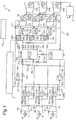
- Fig. 1 illustrates a schematic block diagram of a compressed air energy storage (CAES) power generation device 2.
- CAES compressed air energy storage
- the CAES power generation device 2 includes an air path and a heat medium path.
- air path mainly, compressors 6, a pressure accumulator tank 8, and expanders 10 are provided and connected together fluidically by air pipes 14. Through the inside of the air pipes, air flows (see the dashed line in Fig. 1 ).
- heat medium path mainly, first heat exchangers 16, heat medium tanks 18, and second heat exchangers 22 are provided and connected together fluidically by heat-medium pipes 24. Through the inside of the heat-medium pipes, the heat medium flows (see the solid line in Fig. 1 ).
- the air path will be described with reference to Fig. 1 .
- the drawn air is compressed by the plurality of compressors 6 and stored in the pressure accumulator tank 8.
- the compressed air stored in the pressure accumulator tank 8 is supplied to the plurality of expanders 10 and used for power generation in power generators 36.
- the individual compressors 6 include motors (electric motors) 26.
- the respective motors 26 are mechanically connected to the compressors 6 and electrically connected in parallel with one another. Electric power generated by the renewable energy is supplied to the motors 26, so that the motors 26 are driven with the electric power, and thereby the compressors 6 are operated.
- Discharge ports 6b of the compressors 6 are connected fluidically to the pressure accumulator tank 8 through the air pipes 14.
- Each compressor 6 draws air from a suction port 6a thereinto when driven by the motor 26, compresses the air, and then discharges the compressed air from the discharge port 6b. Consequently, the compressors 6 pressure-feed the compressed air to the pressure accumulator tank 8.
- the plurality of compressors 6 are connected fluidically in parallel with one another, and in the present embodiment, the number of compressors is three. Note that the number of compressors 6 is not limited thereto and only needs to be one or more.
- the pressure accumulator tank 8 stores the compressed air, pressure-fed from the compressors 6. Thus, the pressure accumulator tank 8 can store energy in the form of the compressed air.
- the pressure accumulator tank 8 is connected fluidically to the expanders 10 through the air pipes 14. Thus, the compressed air stored in the pressure accumulator tank 8 is supplied to the expanders 10.
- the plurality of air pipes 14 that extend from the pressure accumulator tank 8 to the individual expanders 10 is provided with flow rate sensors 28a to 28c and switching valves 30a to 30c, respectively. Because of this, the volume of air supplied to the expanders 10 is measured, and the switching valves 30a to 30c are opened and closed as appropriate, thereby making it possible to allow or block the supply of the compressed air to the expanders 10.
- Each expander 10 is of a two-stage type and includes a first-stage expander main body 11 and a second-stage expander main body 12.
- a combination of the first-stage expander main body 11 and the second-stage expander main body 12 may be simply referred to as an "expander 10" in some cases.
- Both the first-stage expander main body 11 and the second-stage expander main body 12 are provided with the respective power generators 36.
- the plurality of power generators 36 is mechanically connected to the respective expanders 10. Concurrently, the power generators 36 are electrically connected in parallel with one another.
- the expanders 10, to which the compressed air is supplied from suction ports 10a are operated by the supplied compressed air to drive the power generators 36.
- Each power generator 36 is electrically connected to the external electric power system 4 (see the alternate long and short dash line in Fig. 1 ).
- the generated electric power is supplied to the electric power system 4 as the demander.
- the air expanded by the expanders 10 is discharged from discharge ports 10b to the outside.
- the plurality of expanders 10 is connected fluidically in parallel to one another, and in the present embodiment, the number of expanders is three. Note that the number of expanders 10 is not limited thereto and only needs to be one or more.
- the heat medium path will be described with reference to Fig. 1 .
- heat generated in the compressors 6 is recovered in the heat medium by the first heat exchangers 16.
- the heat medium having heat recovered therein is stored in the heat medium tanks 18 (a first high-temperature heat medium tank 19 and a second high-temperature heat medium tank 20), and then the heat is returned to the compressed air in the second heat exchangers 22, before the compressed air is expanded by the expanders 10.
- the heat medium having its temperature decreased in the second heat exchangers 22 is supplied to the heat medium tank 18 (the low-temperature heat medium tank 21).
- the heat medium is supplied from the low-temperature heat medium tank 21 to the first heat exchangers 16 again. In this way, the heat medium is circulated.
- the kind of the heat medium is not particularly limited and may be, for example, water, oil, etc.
- Each of the first heat exchangers 16 is provided in the air pipe 14 between the corresponding compressor 6 and the pressure accumulator tank 8. Therefore, heat is exchanged between the compressed air in the air pipe 14 and the heat medium in the heat-medium pipe 24, thereby recovering the compression heat, generated in the compression by the compressors 6, in the heat medium. That is, in the first heat exchangers 16, the temperature of the compressed air is decreased, while the temperature of the heat medium is increased.
- the heat medium having its temperature increased is supplied to the heat medium tanks 18 (the first high-temperature heat medium tank 19 and the second high-temperature heat medium tank 20) through the heat-medium pipes 24.
- the heat-medium pipes 24 from the first heat exchangers 16 to the heat medium tanks 18 are provided with temperature sensors 29a to 29c for measuring the respective temperatures of heat media which have their temperature increased by exchanging heat in the first heat exchangers 16.
- the heat medium tanks 18 include the first high-temperature heat medium tank 19, the second high-temperature heat medium tank 20, and the low-temperature heat medium tank 21.
- a remaining-amount sensor (not shown) is installed to enable detection of the amount of heat medium stored in the tank.
- the remaining-amount sensor may be a gravimetric sensor or the like.
- the first high-temperature heat medium tank 19 and the second high-temperature heat medium tank 20 individually store therein the heat media having their temperatures increased in the first heat exchangers 16, depending on the temperatures of the heat media.
- the first high-temperature heat medium tank 19 stores the heat medium with a higher temperature
- the second high-temperature heat medium tank 20 stores the heat medium with a lower temperature than that of the heat medium in the first high-temperature heat medium tank 19.
- the first high-temperature heat medium tank 19 and the second high-temperature heat medium tank 20 are provided with temperature sensors 29d and 29e, respectively, to enable measurement of the temperature of the heat medium in each tank.
- the heat-medium pipes 24 (the high-temperature heat storage switching lines 24a) from the first heat exchangers 16 to the first high-temperature heat medium tank 19 and to the second high-temperature heat medium tank 20 are provided with high-temperature heat storage switching valves 31a and 31b.
- the high-temperature heat storage switching valves 31a and 31b are to switch the tank for storing the heat medium through the high-temperature heat storage switching line 24a to either the first high-temperature heat medium tank 19 or the second high-temperature heat medium tank 20.
- the heat media stored in the first high-temperature heat medium tank 19 and the second high-temperature heat medium tank 20 are supplied to the second heat exchangers 22 through the heat-medium pipes 24.
- the heat-medium pipes 24 extending from the first high-temperature heat medium tank 19 and the second high-temperature heat medium tank 20 to the second heat exchangers 22 are provided with heat exchange switching valves 32a to 32f.
- the heat exchange switching valves 32a to 32f are to switch the tank from which the heat medium is supplied to the second heat exchanger 22 to either the first high-temperature heat medium tank 19 or the second high-temperature heat medium tank 20.
- the compressed air energy storage power generation device includes the first high-temperature heat medium tank 19 and the second high-temperature heat medium tank 20, thereby making it possible to prevent the high-temperature heat medium from mixing with the low-temperature heat medium.
- the high-temperature heat storage switching valves 31a and 31b are switched based on the temperature of the heat medium having the temperature thereof increased in each first heat exchanger 16. Because of this, the heat media are individually stored in the first high-temperature heat medium tank 19 and the second high-temperature heat medium tank 20, depending on their temperatures, so that the temperature of the heat medium, especially stored in the first high-temperature heat medium tank 19 can be maintained.
- the total number of the high-temperature heat medium tanks 19 and 20 is two, but is not limited thereto and may be three or more.
- Each of the second heat exchangers 22 is provided in the air pipe 14 between the pressure accumulator tank 8 and the corresponding expander 10. Further, another second heat exchanger 22 is provided between each of the first-stage expander main bodies 11 and each of the second-stage expander main bodies 12. Therefore, heat exchange is performed between the heat medium in the heat-medium pipe 24 and each of the compressed air supplied from the pressure accumulator tank 8 to the first-stage expander main body 11 and the compressed air located between the first-stage expander main body 11 and the second-stage expander main body 12, whereby the compressed air is heated before being expanded by the expanders 10. That is, in the second heat exchangers 22, the temperature of the compressed air is increased, while the temperature of each of the heat media is decreased.
- the heat medium having its temperature decreased is supplied to the low-temperature heat medium tank 21 through the heat-medium pipe 24.
- the second heat exchangers 22 can be proposed to be installed by various installation methods, in addition to the installing method of the present embodiment.
- Figs. 2A to 2C illustrate installation examples of the second heat exchangers 22.
- Fig. 2A shows a case in which each second heat exchanger 22 is connected fluidically to each of the first-stage expander main body 11 and the second-stage expander main body 12 in the two-stage type expander 10, like the present embodiment.
- Fig. 2B shows a case in which one second heat exchanger 22 is connected fluidically to a single-stage type expander 10, unlike the present embodiment.
- FIG. 2C shows a case in which two second heat exchangers 22 are connected in series fluidically to each of the first-stage expander main body 11 and the second-stage expander main body 12 in the two-stage type expander 10.
- three or more second heat exchangers 22 may be connected in series fluidically.
- Fig. 3 is a p-h diagram of the two-stage type expander.
- the vertical axis indicates pressure, while the horizontal axis indicates specific enthalpy.
- a process from state P1 to state P2 represents a heating process in the second heat exchanger 22
- a process from state P2 to state P3 represents an expansion work process in the first-stage expander main body 11.
- a process from state P3 to state P4 represents a heating process in the second heat exchanger 22
- a process from state P4 to state P5 represents an expansion work process in the second-stage expander main body 12.
- Fig. 3 shows an isentropic change, provided that the process from state P2 to state P3 and the process from state P4 to state P5 are adiabatic processes.
- a gradient of the isentropic curve from state P4 to state P5 is smaller than a gradient of the isentropic curve from state P2 to state P3, which means that the amount of work performed on an outer side is larger. Therefore, in the case shown in Fig. 3 , the heating amount from state P3 to state P4 is preferably set larger than the heating amount from state P1 to state P2 in terms of the efficiency of the system.
- the low-temperature heat medium tank 21 mainly stores the heat medium having its temperature decreased by exchanging heat in the second heat exchangers 22.
- the temperature of the heat medium in the low-temperature heat medium tank 21 is usually lower than the temperature of the heat medium in each of the first high-temperature heat medium tank 19 and the second high-temperature heat medium tank 20.
- the heat medium stored in the low-temperature heat medium tank 21 is supplied to the first heat exchangers 16 through the heat-medium pipes 24.
- the heat medium circulates through the heat medium path by a pump 38 installed in the heat-medium pipe 24 on the downstream side of the low-temperature heat medium tank 21.
- a flow-rate sensor 28e is provided on the downstream side of the pump 38 and thereby can detect an increase and a decrease in the flow rate of the pump 38. Note that the position of the pump 38 is not limited thereto and may be arranged at an arbitrary position in the heat medium path.
- the first heat exchangers 16 and the second heat exchangers 22 are connected together fluidically via the high-temperature heat medium tanks 19 and 20, and additionally, also connected together fluidically without involvement of the high-temperature heat medium tanks 19 and 20.
- direct inflow switching valves 33a and 33b are provided in the heat-medium pipes 24 (the direct inflow switching lines 24b) on the upstream side with respect to the second heat exchangers 22 and the high-temperature heat medium tanks 19 and 20.
- the direct inflow switching valves 33a and 33b serve to switch the heat medium supplied from the first heat exchanger 16 to the second heat exchanger 22, between a state of flowing through the high-temperature heat medium tanks 19 and 20 and a state of flowing without involvement of the high-temperature heat medium tanks 19 and 20. Furthermore, a flow-rate sensor 28d is provided in the direct inflow switching line 24b that allows the heat medium to flow from the first heat exchangers 16 directly to the second heat exchangers 22.
- the first high-temperature heat medium tank 19 and the low-temperature heat medium tank 21 are connected together fluidically by a heat-medium intertank line 24c.
- the second high-temperature heat medium tank 20 and the low-temperature heat medium tank 21 are connected together fluidically by another heat-medium intertank line 24c.
- intertank shut-off valves 34 are provided in these heat-medium intertank lines 24c.
- each intertank shut-off valve 34 blocks the transfer of the heat medium between these tanks.
- the interbank shut-off valve 34 is opened, enabling the transfer of the heat medium in some cases.
- the transfer of the heat medium is possible even between the first high-temperature heat medium tank 19 and the second high-temperature heat medium tank 20 in some cases.
- the first heat exchangers 16 are fluidically connected to the low-temperature heat medium tank 21 so that the heat medium can be supplied from the first heat exchangers 16 to the low-temperature heat medium tank 21.
- low-temperature heat medium switching valves 35a to 35f serve to switch the supply of the heat medium to either of the high-temperature heat medium tanks 19 and 20 or the low-temperature heat medium tank 21.
- the low-temperature heat medium switching valves 35a to 35f are provided in the heat-medium pipes 24 on the downstream side of the first heat exchangers 16.
- the heat medium path in the CAES power generation device 2 is structured.
- the CAES power generation device 2 includes a control unit 40.
- the control unit 40 is structured by hardware, including storage devices, such as a Central Processing Unit (CPU), a Random Access Memory (RAM), and a Read Only Memory (ROM), and software installed on the hardware.
- the control unit 40 is electrically connected to at least the individual valves 30a to 35f. The operations of the individual valves 30a to 35f are controlled by the control unit 40.
- the flow-rate sensors 28a to 28e, the temperature sensors 29a to 29e, and the remaining-amount sensors (not shown) of the heat medium tanks 18 output measured values to the control unit 40.
- the control unit 40 controls the CAES power generation device 2 based on these measured values.
- the CAES power generation device 2 in the present embodiment has two control methods, namely, simultaneous charging and discharging, which involves simultaneously performing storing (charging) of the compressed air and power generation (discharging) using the compressed air, and separate charging and discharging, which involves separately performing charging and discharging.
- charging means the storing of the compressed air in the pressure accumulator tank 8
- discharging means the power generation by the power generator 36 using the compressed air in the pressure accumulator tank 8.
- the simultaneous charging and discharging is often used when the power generated by using the renewable energy varies in a short-term cycle.
- the separate charging and discharging is often used when the power generated by using the renewable energy varies in a long-term cycle.
- variations in the long-term cycle are those over a period of time from several hours to several days.
- variations in the short-term cycle are those over a period of time from several minutes to less than one hour.
- a factor for variations of the output in the long-term cycle is a day-night difference.
- a factor for variations of the output in the short-term cycle is that the sunlight is temporarily blocked by clouds.
- variations of the output in the long-term cycle occur when the power generation is stopped due to strong wind or no wind, while variations of the output in the short-term cycle occur when the wind speed varies.
- step S4-1 when the operation is started (step S4-1), the control method is determined depending on whether charging and discharging are performed simultaneously (step S4-2). This determination may be selected by the user according to the application or may be made depending on whether the renewable energy varies in the long-term cycle or the short-term cycle.
- step S4-2 if the amount of demand power is larger than a power generation amount, and the whole amount of the heat media in the high-temperature heat medium tanks 19 and 20 are needed (step S4-3), processing A is performed (step S4-4). If not (step S4-3), a necessary amount of heat medium and an excess amount of heat medium are separated from each other (step S4-5).
- the necessary amount of heat medium represents an amount of heat medium that enables the power generator 36 to generate the amount of demand power required by the electric power system 4.
- the heat medium is separated based on the measured value of the flow-rate sensor 28d. The separation is performed by switching the direct inflow switching valves 33a and 33b in the processing A and B, as will be mentioned later. After completion of these processing, the operation returns to step S4-2 again, and the procedure is repeated.
- the compressed air energy storage power generation device used therein falls into the scope of the present invention only if it comprises at least all features of appended independent claim 1, including the controller configuration described in appended independent claim 1.
- the processing steps discussed in the following may comprise additional controller configurations, which are then provided in addition to the configuration described by appended independent claim 1.
- step S5-1 when the processing A is started (step S5-1), the direct inflow switching valves 33a and 33b are switched (step S5-2), specifically, the direct inflow switching valve 33a is opened and the direct inflow switching valve 33b is closed, whereby the heat medium is directly supplied from the first heat exchangers 16 to the second heat exchangers 22 through the heat-medium pipes 24 (step S5-3). Then, heat exchange is performed between the compressed air and the heat medium in each of the second heat exchangers 22 (step S5-4). The heat medium having its temperature decreased by the heat exchange in the second heat exchanger 22 is supplied to and stored in the low-temperature heat medium tank 21 through the heat-medium pipe 24 (step S5-5). Finally, the processing A is finished (step S5-6).
- the heat medium can be directly supplied from the first heat exchangers 16 to the second heat exchangers 22 without involvement of the high-temperature heat medium tanks 19 and 20, thereby making it possible to prevent the loss of heat energy due to a decrease in the temperature of the heat medium while the heat medium is stored in each of the high-temperature heat medium tanks 19 and 20.
- such direct supply of the heat medium is effective because, when variations in the renewable energy in the short-term cycle of less than approximately one hour are intended to be leveled out, the compressor and the expander are simultaneously driven in many cases, and in these cases the usage standby time of the heat medium is short or zero.
- the switching between the direct inflow switching valves can supply the heat medium from the first heat exchangers directly to the second heat exchangers.
- a device which is of the same type as a conventional device can be used, which eliminates the need for significant modification of the device, thereby making it possible to prevent a cost increase and an increase in size of the device.
- the term "direct” as used herein means the supply of the heat medium from the first heat exchangers 16 to the second heat exchangers 22 without involvement of the high-temperature heat medium tanks 19 and 20.
- step S6-1 when the processing B is started (step S6-1), if a temperature T1 of the heat medium, which is heat-exchanged in the first heat exchanger 16, is lower than a heat medium temperature Th1 in the first high-temperature heat medium tank 19 (step S6-2) and further is lower than a heat medium temperature Th2 in the second high-temperature heat medium tank 20 (step S6-3), then the low-temperature heat medium switching valves 35a to 35f are switched (step S6-4).
- the low-temperature heat medium switching valves 35a to 35c are closed, and the low-temperature heat medium switching valves 35d to 35f are opened, whereby the heat medium, heat-exchanged in the first heat exchanger 16, is supplied to and stored in the low-temperature heat medium tank 21 (step S6-5). Meanwhile, if the temperature T1 of the heat medium, heat-exchanged in the first heat exchanger 16, is lower than the heat medium temperature Th1 in the first high-temperature heat medium tank 19 (step S6-2) and further is equal to or higher than the heat medium temperature Th2 in the second high-temperature heat medium tank 20 (step S6-3), then the high-temperature heat storage switching valves 31a and 31b are switched (step S6-6).
- the high-temperature heat storage switching valve 31b is opened, and the high-temperature heat storage switching valve 31a is closed, whereby the heat medium heat-exchanged in the first heat exchanger 16 is supplied to and stored in the second high-temperature heat medium tank 20 (step S6-7). If the temperature T1 of the heat medium, heat-exchanged in the first heat exchanger 16, is equal to or higher than the heat medium temperature Th1 in the first high-temperature heat medium tank 19, the high-temperature heat storage switching valves 31a and 31b are switched (in step S6-8).
- the high-temperature heat storage switching valve 31a is opened, and the high-temperature heat storage switching valve 31b is closed, whereby the heat medium heat-exchanged in the first heat exchanger 16 is supplied to and stored in the first high-temperature heat medium tank 19 (in step S6-8).
- the heat media individually stored in the first high-temperature heat medium tank 19 and the second high-temperature heat medium tank 20 are supplied to the second heat exchangers 22 through the heat-medium pipes 24.
- processing II is performed (step S6-11). If not (step S6-10), processing I is performed (step S6-12). After completion of such processing, the processing B is finished (step S6-13).
- the use of the low-temperature heat medium switching valves 35a to 35f prevents the mixing of the high-temperature heat medium and the low-temperature heat medium.
- the heat medium supplied from the first heat exchangers 16 to the high-temperature heat medium tanks 19 and 20 never decreases the temperature of the heat media having the heat stored in the high-temperature heat medium tanks 19 and 20, thereby making it possible to prevent the loss of the heat energy.
- the use of the high-temperature heat storage switching valves 31a and 31b can individually store the heat medium in the first high-temperature heat medium tank 19 or the second high-temperature heat medium tank 20 depending on the temperature of the heat medium.
- the processing I is performed when only one second heat exchanger 22 is installed with respect to each expander 10 (see Fig. 2B ).
- step S7-1 if the amount of demand power is larger than a power generation amount, and the whole amounts of the heat media in the high-temperature heat medium tanks 19 and 20 are needed (step S7-2), the heat exchange switching valves 32a to 32f are switched (step S7-3), thereby supplying the heat media in the first high-temperature heat medium tank 19 and the second high-temperature heat medium tank 20 to the second heat exchangers 22 (step S7-4).
- heat exchange is performed in the second heat exchangers 22 (step S7-5).
- step S7-2 If not (step S7-2), and if the second high-temperature heat medium tank 20 is empty (step S7-6), the heat exchange switching valves 32a to 32f are switched (step S7-7), thereby supplying the heat medium in the first high-temperature heat medium tank 19 to the second heat exchangers 22 (step S7-8). Subsequently, heat exchange is performed in the second heat exchangers 22 (step S7-9). Meanwhile, if the second high-temperature heat medium tank 20 is not empty (step S7-6), the heat exchange switching valves 32a to 32f are switched (step S7-10), thereby supplying the heat medium in the second high-temperature heat medium tank 20 to the second heat exchangers 22 (step S7-11).
- step S7-12 heat exchange is performed in the second heat exchangers 22 (step S7-12).
- step S7-13 heat exchange switching valves 32a to 32f are switched (step S7-13), thereby supplying the heat medium in the first high-temperature heat medium tank 19 to the second heat exchangers 22 (step S7-14).
- step S7-15 heat exchange is performed in the second heat exchangers 22 (step S7-15). In either case, the heat medium having its temperature decreased by heat exchange in each second heat exchanger 22 is stored in the low-temperature heat medium tank 21 (step S7-6). Finally, the processing I is finished (step S7-17).
- step S8-1 when the processing II is started (step S8-1), if a plurality of the second heat exchangers is installed in series (step S8-2), processing II-2 is executed (step S8-3). If not (step S8-2), processing II-1 is executed (step S8-4). After completion of such processing, the processing II is finished (step S8-5).
- the processing II-1 is performed when one second heat exchanger 22 is installed for each of the first-stage expander main body 11 and the second-stage expander main body 12 (see Fig. 2A ).
- the heat exchange switching valves 32a to 32f are switched (step S9-2).
- the heat medium in the first high-temperature heat medium tank 19 is supplied to the high-temperature side second heat exchanger 22a installed for the expander 10 corresponding to an isentropic curve with a smaller gradient (see Fig.
- step S9-3 while the heat medium in the second high-temperature heat medium tank 20 is supplied to the low-temperature side second heat exchanger 22b installed for the other expander 10 corresponding to an isentropic curve with a larger gradient (see Fig. 3 ) (step S9-3).
- step S9-4 heat exchange is performed in each of the high-temperature side second heat exchanger 22a and the low-temperature side second heat exchanger 22b (step S9-4).
- the heat media, heat-exchanged in the high-temperature side second heat exchanger 22a and the low-temperature side second heat exchanger 22b, are supplied to and stored in the low-temperature heat medium tank 21 through the heat-medium pipe 24 (step S9-5).
- step S9-6 the processing II-1 is finished (step S9-6).
- the high-temperature heat medium is supplied to the second heat exchanger 22 which is installed for one of the first-stage expander main body 11 and the second-stage expander main body 12, corresponding to the isentropic curve with the smaller gradient, so that the power generation can be efficiently performed.
- the expander main body corresponding to the isentropic curve with the smaller gradient undergoes a significant decrease in the enthalpy relative to the same decrease in the pressure, and thereby more heat energy needs to be supplied to such an expander main body.
- the processing II-2 is performed when two second heat exchangers 22 are installed in series for each of the first-stage expander main body 11 and the second-stage expander main body 12 (see Fig. 2C ).
- the heat exchange switching valves 32a to 32f are switched (step S10-2).
- the heat medium in the second high-temperature heat medium tank 20 is supplied to the low-temperature side second heat exchanger 22b located on the upstream side, while the heat medium in the first high-temperature heat medium tank 19 is supplied to the high-temperature side second heat exchanger 22a located on the downstream side (step S10-3).
- step S10-4 heat exchange is performed in the low-temperature side second heat exchanger 22b (step S10-4), and then heat exchange is performed in the high-temperature side second heat exchanger 22a (step S10-5).
- the heat medium having its temperature decreased by the heat exchange in the high-temperature side second heat exchanger 22a and the low-temperature side second heat exchanger 22b is supplied to and stored in the low-temperature heat medium tank 21 (step S10-6).
- step S10-7 the processing II-2 is finished.
- the compressed air exchanges heat with the low-temperature heat medium and the high-temperature heat medium in this order, so that the temperature of the compressed air can be increased in sequence without being decreased.
- the heat medium at a high temperature can be effectively utilized.
- the compressed air only needs to be heat-exchanged with the low-temperature heat medium and the high-temperature heat medium in this order in the same manner.
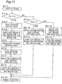
- CAES power generation device 2 in the present embodiment performs optimal control at start-up.
- step S1 1-1 when the CAES power generation device 2 is started up (step S1 1-1), if a temperature T1 of the heat medium, which is heat-exchanged in the first heat exchanger 16, is higher than a heat medium temperature Th1 in the first high-temperature heat medium tank 19 (step S11-2), then the intertank shut-off valve 34 is opened (step S11-3), and the heat medium in the first high-temperature heat medium tank 19 is moved to the low-temperature heat medium tank 21 (step S11-4). Subsequently, the heat medium in the first high-temperature heat medium tank 19 is made empty (step S11-5), and the intertank shut-off valve 34 is closed (step S11-6).
- step S11-7 the high-temperature heat storage switching valves 31a and 31b are switched (step S11-7). Specifically, the high-temperature heat storage switching valve 31a is opened, and the high-temperature heat storage switching valve 31b is closed, whereby the heat medium heat-exchanged in the first heat exchanger 16 is supplied to and stored in the first high-temperature heat medium tank 19 (step S11-8).
- step S11-10 if the temperature T1 of the heat medium, heat-exchanged in the first heat exchanger 16, is equal to or lower than the heat medium temperature Th1 in the first high-temperature heat medium tank 19 (step S11-2) and if temperature T1 of the heat medium, heat-exchanged in the first heat exchanger 16, is higher than the heat medium temperature Th2 in the second high-temperature heat medium tank 20 (step S11-9), the high-temperature heat storage switching valves 31a and 31b are switched (step S11-10).
- the high-temperature heat storage switching valve 31b is opened, and the high-temperature heat storage switching valve 31a is closed, whereby the heat medium heat-exchanged in the first heat exchanger 16 is supplied to and stored in the second high-temperature heat medium tank 20 (step S11-11). If a temperature T1 of the heat medium, which is heat-exchanged in the first heat exchanger 16, is equal to or lower than a heat medium temperature Th2 in the second high-temperature heat medium tank 20 (step S11-9), then the low-temperature heat medium switching valves 35a to 35f are switched (step S11-12).
- step S11-13 the low-temperature heat medium switching valves 35a to 35c are closed, and the low-temperature heat medium switching valves 35d to 35f are opened, whereby the heat medium, heat-exchanged in each first heat exchanger 16, is supplied to and stored in the low-temperature heat medium tank 21 (step S11-13). Then, the operation proceeds to the normal operation (step S11-14).
- the use of the intertank shut-off valve 34 can prevent the mixing of such a low-temperature heat medium with the high-temperature heat medium having the compression heat recovered therein.
- the use of the high-temperature heat storage switching valves 31a and 31b can individually store the heat medium in the high-temperature heat medium tanks 19 and 20 depending on the temperature of the heat medium. Therefore, the temperatures of the heat media having the heat stored in the high-temperature heat medium tanks 19 and 20 are not decreased, thereby making it possible to prevent the loss of the heat energy.
- the heat medium in the first high-temperature heat medium tank 19 is moved to the low-temperature heat medium tank 21 under the predetermined conditions.
- the transfer of the heat medium is not limited thereto. That is, for example, the heat medium in the first high-temperature heat medium tank 19 may be moved to the second high-temperature heat medium tank 20 to make the first high-temperature heat medium tank 19 empty.
- the optimal control can be achieved during the normal operation and at start-up.
- the compressed air energy storage power generation device takes the control methods for the simultaneous charging and discharging and the separate charging and discharging and thus can handle variations in the renewable energy in the short-term cycle and the long-term cycle.
Landscapes
- Engineering & Computer Science (AREA)
- Mechanical Engineering (AREA)
- General Engineering & Computer Science (AREA)
- Chemical & Material Sciences (AREA)
- Combustion & Propulsion (AREA)
- Physics & Mathematics (AREA)
- Thermal Sciences (AREA)
- Power Engineering (AREA)
- Life Sciences & Earth Sciences (AREA)
- High Energy & Nuclear Physics (AREA)
- Sustainable Development (AREA)
- Sustainable Energy (AREA)
- Engine Equipment That Uses Special Cycles (AREA)
- Heat-Pump Type And Storage Water Heaters (AREA)
Claims (4)
- Dispositif de production d'énergie par accumulation d'air comprimé (2), qui comprend :un moteur électrique (26) entraîné avec une énergie électrique apportée produite à l'aide d'une énergie renouvelable ;un compresseur (6) mécaniquement relié au moteur électrique (26) et configuré pour comprimer de l'air ;un réservoir accumulateur de pression (8) fluidiquement relié au compresseur (6) et configuré pour y accumuler l'air comprimé par le compresseur (6) ;un détendeur (10) fluidiquement relié au réservoir accumulateur de pression (8) et entraîné par l'air comprimé fourni depuis le réservoir accumulateur de pression (8) ;un générateur électrique (36) mécaniquement relié au détendeur (10) et configuré pour produire une énergie électrique qui doit être fournie à un demandeur ;un premier échangeur thermique (16) qui échange de la chaleur entre l'air comprimé par le compresseur (6) et un milieu caloporteur pour ainsi chauffer le milieu caloporteur ;un second échangeur thermique (22) ; etun réservoir de milieu caloporteur à basse température (21) fluidiquement relié au premier échangeur thermique (16) et au second échangeur thermique (22), le réservoir de milieu caloporteur à basse température (21) étant configuré pour accumuler le milieu caloporteur dont la température a été diminuée par l'échange de chaleur dans le second échangeur thermique (22) ;caractérisé en ce quele dispositif de production d'énergie par accumulation d'air comprimé (2) comprend en outre :un capteur de température (29a-29c) qui mesure une température du milieu caloporteur, thermiquement échangé dans le premier échangeur thermique (16) ;une pluralité de réservoirs de milieu caloporteur à haute température (19, 20) fluidiquement reliés au premier échangeur thermique (16), la pluralité de réservoirs de milieu caloporteur à haute température (19, 20) étant configurée pour accumuler individuellement le milieu caloporteur dont la température a été augmentée par l'échange de chaleur dans le premier échangeur thermique (16), en fonction de la température du milieu caloporteur ;une vanne de commutation d'accumulation de chaleur à haute température (31a, 31b) pour faire passer le milieu caloporteur fourni depuis le premier échangeur thermique (16) à l'un quelconque de la pluralité de réservoirs de milieu caloporteur à haute température (19, 20) ;le second échangeur thermique (22) qui est fluidiquement relié à la pluralité de réservoirs de milieu caloporteur à haute température (19, 20), le second échangeur thermique (22) étant configuré pour échanger de la chaleur entre le milieu caloporteur fourni depuis chacun de la pluralité de réservoirs de milieu caloporteur à haute température (19, 20) et l'air comprimé fourni au compresseur détendeur (10) pour ainsi chauffer l'air comprimé ;une unité de commande (40) électriquement reliée au capteur de température (29a-29c) et à la vanne de commutation d'accumulation de chaleur à haute température (31a, 31b), l'unité de commande (40) étant configurée pour commuter la vanne de commutation d'accumulation de chaleur à haute température (31a, 31b) afin de fournir le milieu caloporteur depuis le premier échangeur thermique (16) à l'un quelconque de la pluralité de réservoirs de milieu caloporteur à haute température (19, 20), en vue d'accumuler individuellement le milieu caloporteur dans le réservoir de milieu caloporteur à haute température (19, 20) correspondant sur la base d'une température du milieu caloporteur mesurée par le capteur de température (29a-29c), en fonction de la température de celui-ci ; etune vanne de commutation de milieu caloporteur à basse température (35a-35f) configurée pour faire passer le milieu caloporteur fourni depuis le premier échangeur thermique (16) soit au réservoir de milieu caloporteur à haute température (19, 20) soit au réservoir de milieu caloporteur à basse température (21), dans lequell'unité de commande (40) est électriquement reliée au capteur de température (29a-29c) et à la vanne de commutation de milieu caloporteur à basse température (35a-35f), l'unité de commande (40) étant configurée pour commuter la vanne de commutation de milieu caloporteur à basse température (35a-35f) afin de fournir le milieu caloporteur au réservoir de milieu caloporteur à basse température (21) lorsqu'une température du milieu caloporteur avec une chaleur de compression a été récupérée à l'intérieur dans le premier échangeur thermique (16), mesurée par le capteur de température (29a-29c), est inférieure ou égale à une température prédéterminée.
- Dispositif de production d'énergie par accumulation d'air comprimé (2) selon la revendication 1, qui comprend en outre :une vanne de commutation d'admission directe (33a) électriquement reliée à l'unité de commande (40), la vanne de commutation d'admission directe (33a) étant configurée pour faire passer le milieu caloporteur fourni depuis le premier échangeur thermique (16) soit au réservoir de milieu caloporteur à haute température (19, 20) soit au second échangeur thermique (22), dans lequell'unité de commande (40) fournit directement le milieu caloporteur depuis le premier échangeur thermique (16) au second échangeur thermique (22) en commutant la vanne de commutation d'admission directe (33a) lorsqu'il y a réalisation simultanée d'une compression par le compresseur (6) et d'une détente par le détendeur (10).
- Dispositif de production d'énergie par accumulation d'air comprimé (2) selon la revendication 1 ou 2, dans lequel le second échangeur thermique (22) est l'un d'une pluralité de seconds échangeurs thermiques dans le dispositif de production d'énergie par accumulation d'air comprimé (2), la pluralité de seconds échangeurs thermiques (22) étant fluidiquement reliée en série par rapport au détendeur (10), le dispositif de production d'énergie par accumulation d'air comprimé (2) comprenant en outre :une vanne de commutation d'échange de chaleur (32a-32f) pour faire passer le milieu caloporteur fourni depuis le réservoir de milieu caloporteur à haute température (19, 20) à l'un quelconque des seconds échangeurs thermiques (22), dans lequell'unité de commande (40) commute la vanne de commutation d'échange de chaleur (32a-32f) pour fournir chacun des milieux caloporteurs, individuellement accumulés dans les réservoirs de milieu caloporteur à haute température (19, 20) respectifs en fonction de la température du milieu caloporteur, à chacun des seconds échangeurs thermiques (22) depuis un côté en amont dans un ordre ascendant de la température du milieu caloporteur.
- Dispositif de production d'énergie par accumulation d'air comprimé (2) selon la revendication 1 ou 2, qui comprend en outre :une vanne de commutation d'échange de chaleur (32a-32f) pour faire passer le milieu caloporteur fourni depuis le réservoir de milieu caloporteur à haute température (19, 20) à l'un quelconque des seconds échangeurs thermiques (22), dans lequelle détendeur (10) comprend un corps principal de détendeur de premier étage (11) et un corps principal de détendeur de second étage (12), etl'unité de commande (40) commute la vanne de commutation d'échange de chaleur (32a-32f) pour fournir un milieu caloporteur à haute température parmi les milieux caloporteurs, individuellement accumulés dans les réservoirs de milieu caloporteur à haute température (19, 20) respectifs en fonction de la température du milieu caloporteur, au second échangeur thermique (22) fluidiquement relié à l'un parmi le corps principal de détendeur de premier étage (11) et le corps principal de détendeur de second étage (12) qui correspond à une courbe isentropique avec un gradient inférieur dans un diagramme p-h.
Applications Claiming Priority (2)
| Application Number | Priority Date | Filing Date | Title |
|---|---|---|---|
| JP2015096773A JP6387325B2 (ja) | 2015-05-11 | 2015-05-11 | 圧縮空気貯蔵発電装置 |
| PCT/JP2016/062823 WO2016181798A1 (fr) | 2015-05-11 | 2016-04-22 | Dispositif de génération d'énergie par stockage d'air comprimé |
Publications (3)
| Publication Number | Publication Date |
|---|---|
| EP3296544A1 EP3296544A1 (fr) | 2018-03-21 |
| EP3296544A4 EP3296544A4 (fr) | 2018-12-26 |
| EP3296544B1 true EP3296544B1 (fr) | 2021-06-30 |
Family
ID=57249129
Family Applications (1)
| Application Number | Title | Priority Date | Filing Date |
|---|---|---|---|
| EP16792523.9A Active EP3296544B1 (fr) | 2015-05-11 | 2016-04-22 | Dispositif de génération d'énergie par stockage d'air comprimé |
Country Status (5)
| Country | Link |
|---|---|
| US (1) | US10344628B2 (fr) |
| EP (1) | EP3296544B1 (fr) |
| JP (1) | JP6387325B2 (fr) |
| CN (1) | CN107532512B (fr) |
| WO (1) | WO2016181798A1 (fr) |
Families Citing this family (31)
| Publication number | Priority date | Publication date | Assignee | Title |
|---|---|---|---|---|
| JP6614878B2 (ja) * | 2014-12-25 | 2019-12-04 | 株式会社神戸製鋼所 | 圧縮空気貯蔵発電装置及び圧縮空気貯蔵発電方法 |
| JP6752751B2 (ja) * | 2017-04-17 | 2020-09-09 | 株式会社神戸製鋼所 | 圧縮空気貯蔵発電装置 |
| JP6705770B2 (ja) * | 2017-04-21 | 2020-06-03 | 株式会社神戸製鋼所 | 圧縮空気貯蔵発電装置 |
| JP6731377B2 (ja) * | 2017-04-26 | 2020-07-29 | 株式会社神戸製鋼所 | 圧縮空気貯蔵発電装置及び圧縮空気貯蔵発電方法 |
| JP6826962B2 (ja) * | 2017-07-25 | 2021-02-10 | 株式会社神戸製鋼所 | 圧縮空気貯蔵発電装置及び圧縮空気貯蔵発電方法 |
| JP6817908B2 (ja) * | 2017-08-01 | 2021-01-20 | 株式会社神戸製鋼所 | 圧縮空気貯蔵発電装置及び方法 |
| JP6910969B2 (ja) | 2018-01-09 | 2021-07-28 | 株式会社神戸製鋼所 | 圧縮空気貯蔵発電装置および圧縮空気貯蔵発電方法 |
| CN108316982B (zh) * | 2018-04-18 | 2023-11-24 | 贵州电网有限责任公司 | 一种压缩空气储能膨胀机系统及其控制方法 |
| JP2020122428A (ja) * | 2019-01-30 | 2020-08-13 | 株式会社神戸製鋼所 | 圧縮空気貯蔵発電装置及び圧縮空気貯蔵発電方法 |
| JP2021076056A (ja) * | 2019-11-07 | 2021-05-20 | 住友重機械工業株式会社 | 発電システム、制御装置及び発電方法 |
| JP2022011690A (ja) * | 2020-06-30 | 2022-01-17 | 株式会社神戸製鋼所 | 圧縮空気貯蔵発電装置および圧縮空気貯蔵発電方法 |
| CN114087901B (zh) * | 2020-08-05 | 2024-04-23 | 中节能国机联合电力(宁夏)有限公司 | 一种高温烟气储热系统 |
| CN112302743B (zh) * | 2020-10-30 | 2023-02-03 | 华北电力科学研究院有限责任公司 | 用于压缩空气储能电站的膨胀发电系统及其运行控制方法 |
| CN112985144B (zh) * | 2021-02-07 | 2022-04-01 | 百穰新能源科技(深圳)有限公司 | 基于二氧化碳气液相变的多级压缩储能装置及方法 |
| CN114962222B (zh) * | 2021-02-23 | 2023-09-01 | 国网湖北省电力有限公司 | 先进绝热压缩空气储能能量枢纽设备及其建模方法 |
| CN113464406A (zh) * | 2021-07-26 | 2021-10-01 | 中节能工程技术研究院有限公司 | 压缩空气储能系统及可再生能源系统 |
| CN114526134B (zh) * | 2022-01-28 | 2024-04-30 | 中国能源建设集团江苏省电力设计院有限公司 | 基于压缩空气储能发电系统的调相机系统及其运行方法 |
| US12104493B2 (en) * | 2022-04-08 | 2024-10-01 | Sapphire Technologies, Inc. | Producing power with turboexpander generators based on specified output conditions |
| US11619140B1 (en) | 2022-04-08 | 2023-04-04 | Sapphire Technologies, Inc. | Producing power with turboexpander generators based on specified output conditions |
| GB2618583A (en) * | 2022-05-11 | 2023-11-15 | Corre Energy B V | Compressed Air Energy Storage System |
| US12258887B2 (en) | 2022-07-25 | 2025-03-25 | Sapphire Technologies, Inc. | Cooling gas recovered from a well |
| US12286953B2 (en) | 2022-07-25 | 2025-04-29 | Sapphire Technologies, Inc. | Energy recovery from a gas well |
| US12449195B2 (en) | 2022-07-25 | 2025-10-21 | Sapphire Technologies, Inc. | Conditioning gas for a pipeline |
| JP7793496B2 (ja) * | 2022-08-24 | 2026-01-05 | コベルコ・コンプレッサ株式会社 | 空気圧縮機の性能試験システムおよびエネルギー回収方法 |
| US11795873B1 (en) * | 2022-09-07 | 2023-10-24 | Sapphire Technologies, Inc. | Modular design of turboexpander components |
| CN116122926A (zh) * | 2023-02-03 | 2023-05-16 | 中国华电科工集团有限公司 | 一种压缩空气储能系统及方法 |
| CN116608113B (zh) * | 2023-06-08 | 2026-01-20 | 上海发电设备成套设计研究院有限责任公司 | 压缩空气储能运行系统和储能方法 |
| CN116928070A (zh) * | 2023-09-04 | 2023-10-24 | 佛山国标储能科技有限公司 | 一种压缩空气储能系统及其应用方法 |
| CN117662270B (zh) * | 2023-11-29 | 2024-06-14 | 国家能源蓬莱发电有限公司 | 一种利用外界热源的压缩空气储能系统及方法 |
| WO2025227109A1 (fr) * | 2024-04-26 | 2025-10-30 | Spar Systems Inc. | Système de conversion de chaleur en énergie à impulsions séquentielles |
| US12345198B1 (en) * | 2024-07-09 | 2025-07-01 | Schlumberger Technology Corporation | Thermal impact of gas storage |
Family Cites Families (12)
| Publication number | Priority date | Publication date | Assignee | Title |
|---|---|---|---|---|
| JPS6155592A (ja) * | 1984-08-24 | 1986-03-20 | Matsushita Electric Works Ltd | 蓄熱装置 |
| DE8801767U1 (de) * | 1988-02-11 | 1988-07-07 | Fa. Otto Wehrle, 7815 Kirchzarten | Vorrichtung zur Erwärmung und Speicherung insbesondere von Brauchwasser |
| ATE147135T1 (de) | 1991-06-17 | 1997-01-15 | Electric Power Res Inst | Energieanlage mit komprimiertem luftspeicher |
| US8261552B2 (en) * | 2007-01-25 | 2012-09-11 | Dresser Rand Company | Advanced adiabatic compressed air energy storage system |
| CN101289963A (zh) * | 2007-04-18 | 2008-10-22 | 中国科学院工程热物理研究所 | 压缩空气储能系统 |
| DE202009018043U1 (de) * | 2009-03-09 | 2010-12-02 | Rawema Countertrade Handelsgesellschaft Mbh | Wärmespeichersystem |
| EP2554804B1 (fr) * | 2009-06-18 | 2016-12-14 | ABB Research Ltd. | Système de stockage d'énergie avec un réservoir de stockage intermédiaire et procédé de stockage d'énergie thermoélectrique |
| US20110094231A1 (en) | 2009-10-28 | 2011-04-28 | Freund Sebastian W | Adiabatic compressed air energy storage system with multi-stage thermal energy storage |
| US20110100010A1 (en) | 2009-10-30 | 2011-05-05 | Freund Sebastian W | Adiabatic compressed air energy storage system with liquid thermal energy storage |
| US20120102987A1 (en) * | 2010-10-29 | 2012-05-03 | Nuovo Pignone S.P.A. | Inlet Air Cooling and Moisture Removal Methods and Devices in Advance Adiabatic Compressed Air Energy Storage Systems |
| GB2493726A (en) * | 2011-08-16 | 2013-02-20 | Alstom Technology Ltd | Adiabatic compressed air energy storage system |
| CN103452612B (zh) | 2013-08-28 | 2015-01-28 | 中国科学院工程热物理研究所 | 一种以二氧化碳为工质的压缩气体储能系统 |
-
2015
- 2015-05-11 JP JP2015096773A patent/JP6387325B2/ja not_active Expired - Fee Related
-
2016
- 2016-04-22 US US15/572,441 patent/US10344628B2/en active Active
- 2016-04-22 CN CN201680027001.2A patent/CN107532512B/zh not_active Expired - Fee Related
- 2016-04-22 WO PCT/JP2016/062823 patent/WO2016181798A1/fr not_active Ceased
- 2016-04-22 EP EP16792523.9A patent/EP3296544B1/fr active Active
Also Published As
| Publication number | Publication date |
|---|---|
| JP6387325B2 (ja) | 2018-09-05 |
| CN107532512A (zh) | 2018-01-02 |
| WO2016181798A1 (fr) | 2016-11-17 |
| US20180171832A1 (en) | 2018-06-21 |
| EP3296544A1 (fr) | 2018-03-21 |
| EP3296544A4 (fr) | 2018-12-26 |
| JP2016211464A (ja) | 2016-12-15 |
| CN107532512B (zh) | 2020-02-11 |
| US10344628B2 (en) | 2019-07-09 |
Similar Documents
| Publication | Publication Date | Title |
|---|---|---|
| EP3296544B1 (fr) | Dispositif de génération d'énergie par stockage d'air comprimé | |
| JP6358981B2 (ja) | 圧縮空気貯蔵発電装置及び圧縮空気貯蔵発電方法 | |
| JP6614878B2 (ja) | 圧縮空気貯蔵発電装置及び圧縮空気貯蔵発電方法 | |
| US7802426B2 (en) | System and method for rapid isothermal gas expansion and compression for energy storage | |
| US20150236527A1 (en) | Asymmetric dispatching systems, devices, and methods | |
| CN107532510A (zh) | 压缩空气储能发电方法及压缩空气储能发电装置 | |
| JP6649141B2 (ja) | 圧縮空気貯蔵発電装置 | |
| CN112867855B (zh) | 压缩空气储能发电装置及压缩空气储能发电方法 | |
| CN116667399B (zh) | 一种串联储能系统、储能方法及发电方法 | |
| CN108930911B (zh) | 一种加氢站氢能源的供给方法及系统 | |
| WO2016104222A1 (fr) | Dispositif et procédé de génération électrique avec stockage d'air comprimé | |
| JP2025063773A (ja) | 圧縮空気エネルギ貯蔵装置 | |
| JP2018178887A (ja) | 圧縮空気貯蔵発電装置 | |
| EP4715180A1 (fr) | Dispositif de stockage d'énergie à air comprimé | |
| CN212690123U (zh) | 一种多能联合发电系统 | |
| TWI592573B (zh) | Solar collector fluid temperature difference air booster power plant | |
| WO2026028590A1 (fr) | Dispositif de stockage d'énergie à air comprimé et dispositif de stockage d'énergie | |
| JP2026065911A (ja) | 揚水発電設備 | |
| EP4332456A1 (fr) | Chauffe-eau à pompe à chaleur de type à stockage d'eau chaude | |
| CN117318316A (zh) | 一种气液耦合储能系统及其工作方法 | |
| Jiang et al. | Investigation and Optimization of the Thermal Performances of Compressed Sco2 Energy Storage System Based on Dynamic Modeling and Transient Simulation | |
| Sevilla Camacho et al. | Intelligent Reconfiguration Method for Pv Water-Pumping System with Partial Shading and Variable Pump Head |
Legal Events
| Date | Code | Title | Description |
|---|---|---|---|
| STAA | Information on the status of an ep patent application or granted ep patent |
Free format text: STATUS: THE INTERNATIONAL PUBLICATION HAS BEEN MADE |
|
| PUAI | Public reference made under article 153(3) epc to a published international application that has entered the european phase |
Free format text: ORIGINAL CODE: 0009012 |
|
| STAA | Information on the status of an ep patent application or granted ep patent |
Free format text: STATUS: REQUEST FOR EXAMINATION WAS MADE |
|
| 17P | Request for examination filed |
Effective date: 20171026 |
|
| AK | Designated contracting states |
Kind code of ref document: A1 Designated state(s): AL AT BE BG CH CY CZ DE DK EE ES FI FR GB GR HR HU IE IS IT LI LT LU LV MC MK MT NL NO PL PT RO RS SE SI SK SM TR |
|
| AX | Request for extension of the european patent |
Extension state: BA ME |
|
| DAV | Request for validation of the european patent (deleted) | ||
| DAX | Request for extension of the european patent (deleted) | ||
| A4 | Supplementary search report drawn up and despatched |
Effective date: 20181127 |
|
| RIC1 | Information provided on ipc code assigned before grant |
Ipc: H02J 15/00 20060101ALI20181121BHEP Ipc: F02C 1/05 20060101ALI20181121BHEP Ipc: F01K 3/12 20060101ALI20181121BHEP Ipc: H02K 51/00 20060101ALI20181121BHEP Ipc: F01K 27/00 20060101ALI20181121BHEP Ipc: H02K 7/14 20060101ALI20181121BHEP Ipc: F28D 20/00 20060101ALI20181121BHEP Ipc: F01K 27/02 20060101ALI20181121BHEP Ipc: F02C 1/04 20060101ALI20181121BHEP Ipc: F01D 15/10 20060101ALI20181121BHEP Ipc: F02C 6/16 20060101AFI20181121BHEP |
|
| RIC1 | Information provided on ipc code assigned before grant |
Ipc: H02K 51/00 20060101ALI20201216BHEP Ipc: F01K 3/12 20060101ALI20201216BHEP Ipc: F01K 27/02 20060101ALI20201216BHEP Ipc: H02K 7/14 20060101ALI20201216BHEP Ipc: F28D 20/00 20060101ALI20201216BHEP Ipc: F02C 1/04 20060101ALI20201216BHEP Ipc: H02J 15/00 20060101ALI20201216BHEP Ipc: F01D 15/10 20060101ALI20201216BHEP Ipc: F01K 27/00 20060101ALI20201216BHEP Ipc: F02C 1/05 20060101ALI20201216BHEP Ipc: F02C 6/16 20060101AFI20201216BHEP |
|
| GRAP | Despatch of communication of intention to grant a patent |
Free format text: ORIGINAL CODE: EPIDOSNIGR1 |
|
| STAA | Information on the status of an ep patent application or granted ep patent |
Free format text: STATUS: GRANT OF PATENT IS INTENDED |
|
| INTG | Intention to grant announced |
Effective date: 20210204 |
|
| GRAS | Grant fee paid |
Free format text: ORIGINAL CODE: EPIDOSNIGR3 |
|
| GRAA | (expected) grant |
Free format text: ORIGINAL CODE: 0009210 |
|
| STAA | Information on the status of an ep patent application or granted ep patent |
Free format text: STATUS: THE PATENT HAS BEEN GRANTED |
|
| AK | Designated contracting states |
Kind code of ref document: B1 Designated state(s): AL AT BE BG CH CY CZ DE DK EE ES FI FR GB GR HR HU IE IS IT LI LT LU LV MC MK MT NL NO PL PT RO RS SE SI SK SM TR |
|
| REG | Reference to a national code |
Ref country code: CH Ref legal event code: EP |
|
| REG | Reference to a national code |
Ref country code: DE Ref legal event code: R096 Ref document number: 602016060043 Country of ref document: DE Ref country code: AT Ref legal event code: REF Ref document number: 1406552 Country of ref document: AT Kind code of ref document: T Effective date: 20210715 |
|
| REG | Reference to a national code |
Ref country code: IE Ref legal event code: FG4D |
|
| REG | Reference to a national code |
Ref country code: LT Ref legal event code: MG9D |
|
| PG25 | Lapsed in a contracting state [announced via postgrant information from national office to epo] |
Ref country code: HR Free format text: LAPSE BECAUSE OF FAILURE TO SUBMIT A TRANSLATION OF THE DESCRIPTION OR TO PAY THE FEE WITHIN THE PRESCRIBED TIME-LIMIT Effective date: 20210630 Ref country code: BG Free format text: LAPSE BECAUSE OF FAILURE TO SUBMIT A TRANSLATION OF THE DESCRIPTION OR TO PAY THE FEE WITHIN THE PRESCRIBED TIME-LIMIT Effective date: 20210930 Ref country code: FI Free format text: LAPSE BECAUSE OF FAILURE TO SUBMIT A TRANSLATION OF THE DESCRIPTION OR TO PAY THE FEE WITHIN THE PRESCRIBED TIME-LIMIT Effective date: 20210630 |
|
| REG | Reference to a national code |
Ref country code: NL Ref legal event code: MP Effective date: 20210630 |
|
| REG | Reference to a national code |
Ref country code: AT Ref legal event code: MK05 Ref document number: 1406552 Country of ref document: AT Kind code of ref document: T Effective date: 20210630 |
|
| PG25 | Lapsed in a contracting state [announced via postgrant information from national office to epo] |
Ref country code: GR Free format text: LAPSE BECAUSE OF FAILURE TO SUBMIT A TRANSLATION OF THE DESCRIPTION OR TO PAY THE FEE WITHIN THE PRESCRIBED TIME-LIMIT Effective date: 20211001 Ref country code: LV Free format text: LAPSE BECAUSE OF FAILURE TO SUBMIT A TRANSLATION OF THE DESCRIPTION OR TO PAY THE FEE WITHIN THE PRESCRIBED TIME-LIMIT Effective date: 20210630 Ref country code: RS Free format text: LAPSE BECAUSE OF FAILURE TO SUBMIT A TRANSLATION OF THE DESCRIPTION OR TO PAY THE FEE WITHIN THE PRESCRIBED TIME-LIMIT Effective date: 20210630 Ref country code: SE Free format text: LAPSE BECAUSE OF FAILURE TO SUBMIT A TRANSLATION OF THE DESCRIPTION OR TO PAY THE FEE WITHIN THE PRESCRIBED TIME-LIMIT Effective date: 20210630 Ref country code: NO Free format text: LAPSE BECAUSE OF FAILURE TO SUBMIT A TRANSLATION OF THE DESCRIPTION OR TO PAY THE FEE WITHIN THE PRESCRIBED TIME-LIMIT Effective date: 20210930 |
|
| PG25 | Lapsed in a contracting state [announced via postgrant information from national office to epo] |
Ref country code: SK Free format text: LAPSE BECAUSE OF FAILURE TO SUBMIT A TRANSLATION OF THE DESCRIPTION OR TO PAY THE FEE WITHIN THE PRESCRIBED TIME-LIMIT Effective date: 20210630 Ref country code: SM Free format text: LAPSE BECAUSE OF FAILURE TO SUBMIT A TRANSLATION OF THE DESCRIPTION OR TO PAY THE FEE WITHIN THE PRESCRIBED TIME-LIMIT Effective date: 20210630 Ref country code: EE Free format text: LAPSE BECAUSE OF FAILURE TO SUBMIT A TRANSLATION OF THE DESCRIPTION OR TO PAY THE FEE WITHIN THE PRESCRIBED TIME-LIMIT Effective date: 20210630 Ref country code: CZ Free format text: LAPSE BECAUSE OF FAILURE TO SUBMIT A TRANSLATION OF THE DESCRIPTION OR TO PAY THE FEE WITHIN THE PRESCRIBED TIME-LIMIT Effective date: 20210630 Ref country code: RO Free format text: LAPSE BECAUSE OF FAILURE TO SUBMIT A TRANSLATION OF THE DESCRIPTION OR TO PAY THE FEE WITHIN THE PRESCRIBED TIME-LIMIT Effective date: 20210630 Ref country code: PT Free format text: LAPSE BECAUSE OF FAILURE TO SUBMIT A TRANSLATION OF THE DESCRIPTION OR TO PAY THE FEE WITHIN THE PRESCRIBED TIME-LIMIT Effective date: 20211102 Ref country code: NL Free format text: LAPSE BECAUSE OF FAILURE TO SUBMIT A TRANSLATION OF THE DESCRIPTION OR TO PAY THE FEE WITHIN THE PRESCRIBED TIME-LIMIT Effective date: 20210630 Ref country code: ES Free format text: LAPSE BECAUSE OF FAILURE TO SUBMIT A TRANSLATION OF THE DESCRIPTION OR TO PAY THE FEE WITHIN THE PRESCRIBED TIME-LIMIT Effective date: 20210630 Ref country code: AT Free format text: LAPSE BECAUSE OF FAILURE TO SUBMIT A TRANSLATION OF THE DESCRIPTION OR TO PAY THE FEE WITHIN THE PRESCRIBED TIME-LIMIT Effective date: 20210630 |
|
| PG25 | Lapsed in a contracting state [announced via postgrant information from national office to epo] |
Ref country code: PL Free format text: LAPSE BECAUSE OF FAILURE TO SUBMIT A TRANSLATION OF THE DESCRIPTION OR TO PAY THE FEE WITHIN THE PRESCRIBED TIME-LIMIT Effective date: 20210630 |
|
| REG | Reference to a national code |
Ref country code: DE Ref legal event code: R097 Ref document number: 602016060043 Country of ref document: DE |
|
| PG25 | Lapsed in a contracting state [announced via postgrant information from national office to epo] |
Ref country code: DK Free format text: LAPSE BECAUSE OF FAILURE TO SUBMIT A TRANSLATION OF THE DESCRIPTION OR TO PAY THE FEE WITHIN THE PRESCRIBED TIME-LIMIT Effective date: 20210630 |
|
| PLBE | No opposition filed within time limit |
Free format text: ORIGINAL CODE: 0009261 |
|
| STAA | Information on the status of an ep patent application or granted ep patent |
Free format text: STATUS: NO OPPOSITION FILED WITHIN TIME LIMIT |
|
| PG25 | Lapsed in a contracting state [announced via postgrant information from national office to epo] |
Ref country code: AL Free format text: LAPSE BECAUSE OF FAILURE TO SUBMIT A TRANSLATION OF THE DESCRIPTION OR TO PAY THE FEE WITHIN THE PRESCRIBED TIME-LIMIT Effective date: 20210630 |
|
| 26N | No opposition filed |
Effective date: 20220331 |
|
| PG25 | Lapsed in a contracting state [announced via postgrant information from national office to epo] |
Ref country code: IT Free format text: LAPSE BECAUSE OF FAILURE TO SUBMIT A TRANSLATION OF THE DESCRIPTION OR TO PAY THE FEE WITHIN THE PRESCRIBED TIME-LIMIT Effective date: 20210630 |
|
| REG | Reference to a national code |
Ref country code: CH Ref legal event code: PL |
|
| REG | Reference to a national code |
Ref country code: BE Ref legal event code: MM Effective date: 20220430 |
|
| PG25 | Lapsed in a contracting state [announced via postgrant information from national office to epo] |
Ref country code: MC Free format text: LAPSE BECAUSE OF FAILURE TO SUBMIT A TRANSLATION OF THE DESCRIPTION OR TO PAY THE FEE WITHIN THE PRESCRIBED TIME-LIMIT Effective date: 20210630 Ref country code: LU Free format text: LAPSE BECAUSE OF NON-PAYMENT OF DUE FEES Effective date: 20220422 Ref country code: LI Free format text: LAPSE BECAUSE OF NON-PAYMENT OF DUE FEES Effective date: 20220430 Ref country code: FR Free format text: LAPSE BECAUSE OF NON-PAYMENT OF DUE FEES Effective date: 20220430 Ref country code: CH Free format text: LAPSE BECAUSE OF NON-PAYMENT OF DUE FEES Effective date: 20220430 |
|
| PG25 | Lapsed in a contracting state [announced via postgrant information from national office to epo] |
Ref country code: BE Free format text: LAPSE BECAUSE OF NON-PAYMENT OF DUE FEES Effective date: 20220430 |
|
| PG25 | Lapsed in a contracting state [announced via postgrant information from national office to epo] |
Ref country code: LT Free format text: LAPSE BECAUSE OF FAILURE TO SUBMIT A TRANSLATION OF THE DESCRIPTION OR TO PAY THE FEE WITHIN THE PRESCRIBED TIME-LIMIT Effective date: 20210630 Ref country code: IE Free format text: LAPSE BECAUSE OF NON-PAYMENT OF DUE FEES Effective date: 20220422 |
|
| P01 | Opt-out of the competence of the unified patent court (upc) registered |
Effective date: 20230523 |
|
| PGFP | Annual fee paid to national office [announced via postgrant information from national office to epo] |
Ref country code: DE Payment date: 20230228 Year of fee payment: 8 |
|
| PG25 | Lapsed in a contracting state [announced via postgrant information from national office to epo] |
Ref country code: HU Free format text: LAPSE BECAUSE OF FAILURE TO SUBMIT A TRANSLATION OF THE DESCRIPTION OR TO PAY THE FEE WITHIN THE PRESCRIBED TIME-LIMIT; INVALID AB INITIO Effective date: 20160422 |
|
| PG25 | Lapsed in a contracting state [announced via postgrant information from national office to epo] |
Ref country code: MK Free format text: LAPSE BECAUSE OF FAILURE TO SUBMIT A TRANSLATION OF THE DESCRIPTION OR TO PAY THE FEE WITHIN THE PRESCRIBED TIME-LIMIT Effective date: 20210630 Ref country code: CY Free format text: LAPSE BECAUSE OF FAILURE TO SUBMIT A TRANSLATION OF THE DESCRIPTION OR TO PAY THE FEE WITHIN THE PRESCRIBED TIME-LIMIT Effective date: 20210630 |
|
| PGFP | Annual fee paid to national office [announced via postgrant information from national office to epo] |
Ref country code: GB Payment date: 20240229 Year of fee payment: 9 |
|
| PG25 | Lapsed in a contracting state [announced via postgrant information from national office to epo] |
Ref country code: TR Free format text: LAPSE BECAUSE OF FAILURE TO SUBMIT A TRANSLATION OF THE DESCRIPTION OR TO PAY THE FEE WITHIN THE PRESCRIBED TIME-LIMIT Effective date: 20210630 |
|
| PG25 | Lapsed in a contracting state [announced via postgrant information from national office to epo] |
Ref country code: MT Free format text: LAPSE BECAUSE OF FAILURE TO SUBMIT A TRANSLATION OF THE DESCRIPTION OR TO PAY THE FEE WITHIN THE PRESCRIBED TIME-LIMIT Effective date: 20210630 |
|
| REG | Reference to a national code |
Ref country code: DE Ref legal event code: R119 Ref document number: 602016060043 Country of ref document: DE |
|
| PG25 | Lapsed in a contracting state [announced via postgrant information from national office to epo] |
Ref country code: DE Free format text: LAPSE BECAUSE OF NON-PAYMENT OF DUE FEES Effective date: 20241105 |
|
| PG25 | Lapsed in a contracting state [announced via postgrant information from national office to epo] |
Ref country code: DE Free format text: LAPSE BECAUSE OF NON-PAYMENT OF DUE FEES Effective date: 20241105 |
|
| GBPC | Gb: european patent ceased through non-payment of renewal fee |
Effective date: 20250422 |
|
| PG25 | Lapsed in a contracting state [announced via postgrant information from national office to epo] |
Ref country code: GB Free format text: LAPSE BECAUSE OF NON-PAYMENT OF DUE FEES Effective date: 20250422 |