EP3296560A1 - Système d'allumage - Google Patents
Système d'allumage Download PDFInfo
- Publication number
- EP3296560A1 EP3296560A1 EP16796381.8A EP16796381A EP3296560A1 EP 3296560 A1 EP3296560 A1 EP 3296560A1 EP 16796381 A EP16796381 A EP 16796381A EP 3296560 A1 EP3296560 A1 EP 3296560A1
- Authority
- EP
- European Patent Office
- Prior art keywords
- circuit
- spark
- discharge
- threshold value
- ignition
- Prior art date
- Legal status (The legal status is an assumption and is not a legal conclusion. Google has not performed a legal analysis and makes no representation as to the accuracy of the status listed.)
- Granted
Links
Images




Classifications
-
- F—MECHANICAL ENGINEERING; LIGHTING; HEATING; WEAPONS; BLASTING
- F02—COMBUSTION ENGINES; HOT-GAS OR COMBUSTION-PRODUCT ENGINE PLANTS
- F02P—IGNITION, OTHER THAN COMPRESSION IGNITION, FOR INTERNAL-COMBUSTION ENGINES; TESTING OF IGNITION TIMING IN COMPRESSION-IGNITION ENGINES
- F02P15/00—Electric spark ignition having characteristics not provided for in, or of interest apart from, groups F02P1/00 - F02P13/00 and combined with layout of ignition circuits
- F02P15/10—Electric spark ignition having characteristics not provided for in, or of interest apart from, groups F02P1/00 - F02P13/00 and combined with layout of ignition circuits having continuous electric sparks
-
- F—MECHANICAL ENGINEERING; LIGHTING; HEATING; WEAPONS; BLASTING
- F02—COMBUSTION ENGINES; HOT-GAS OR COMBUSTION-PRODUCT ENGINE PLANTS
- F02P—IGNITION, OTHER THAN COMPRESSION IGNITION, FOR INTERNAL-COMBUSTION ENGINES; TESTING OF IGNITION TIMING IN COMPRESSION-IGNITION ENGINES
- F02P17/00—Testing of ignition installations, e.g. in combination with adjusting; Testing of ignition timing in compression-ignition engines
- F02P17/12—Testing characteristics of the spark, ignition voltage or current
-
- F—MECHANICAL ENGINEERING; LIGHTING; HEATING; WEAPONS; BLASTING
- F02—COMBUSTION ENGINES; HOT-GAS OR COMBUSTION-PRODUCT ENGINE PLANTS
- F02P—IGNITION, OTHER THAN COMPRESSION IGNITION, FOR INTERNAL-COMBUSTION ENGINES; TESTING OF IGNITION TIMING IN COMPRESSION-IGNITION ENGINES
- F02P3/00—Other installations
- F02P3/02—Other installations having inductive energy storage, e.g. arrangements of induction coils
- F02P3/04—Layout of circuits
- F02P3/05—Layout of circuits for control of the magnitude of the current in the ignition coil
- F02P3/051—Opening or closing the primary coil circuit with semiconductor devices
- F02P3/053—Opening or closing the primary coil circuit with semiconductor devices using digital techniques
-
- F—MECHANICAL ENGINEERING; LIGHTING; HEATING; WEAPONS; BLASTING
- F02—COMBUSTION ENGINES; HOT-GAS OR COMBUSTION-PRODUCT ENGINE PLANTS
- F02P—IGNITION, OTHER THAN COMPRESSION IGNITION, FOR INTERNAL-COMBUSTION ENGINES; TESTING OF IGNITION TIMING IN COMPRESSION-IGNITION ENGINES
- F02P9/00—Electric spark ignition control, not otherwise provided for
- F02P9/002—Control of spark intensity, intensifying, lengthening, suppression
- F02P9/007—Control of spark intensity, intensifying, lengthening, suppression by supplementary electrical discharge in the pre-ionised electrode interspace of the sparking plug, e.g. plasma jet ignition
-
- H—ELECTRICITY
- H01—ELECTRIC ELEMENTS
- H01T—SPARK GAPS; OVERVOLTAGE ARRESTERS USING SPARK GAPS; SPARKING PLUGS; CORONA DEVICES; GENERATING IONS TO BE INTRODUCED INTO NON-ENCLOSED GASES
- H01T13/00—Sparking plugs
- H01T13/58—Testing
-
- F—MECHANICAL ENGINEERING; LIGHTING; HEATING; WEAPONS; BLASTING
- F02—COMBUSTION ENGINES; HOT-GAS OR COMBUSTION-PRODUCT ENGINE PLANTS
- F02D—CONTROLLING COMBUSTION ENGINES
- F02D35/00—Controlling engines, dependent on conditions exterior or interior to engines, not otherwise provided for
- F02D35/02—Controlling engines, dependent on conditions exterior or interior to engines, not otherwise provided for on interior conditions
- F02D35/023—Controlling engines, dependent on conditions exterior or interior to engines, not otherwise provided for on interior conditions by determining the cylinder pressure
-
- F—MECHANICAL ENGINEERING; LIGHTING; HEATING; WEAPONS; BLASTING
- F02—COMBUSTION ENGINES; HOT-GAS OR COMBUSTION-PRODUCT ENGINE PLANTS
- F02D—CONTROLLING COMBUSTION ENGINES
- F02D41/00—Electrical control of supply of combustible mixture or its constituents
- F02D41/02—Circuit arrangements for generating control signals
- F02D41/14—Introducing closed-loop corrections
- F02D41/1438—Introducing closed-loop corrections using means for determining characteristics of the combustion gases; Sensors therefor
- F02D41/1444—Introducing closed-loop corrections using means for determining characteristics of the combustion gases; Sensors therefor characterised by the characteristics of the combustion gases
- F02D41/1454—Introducing closed-loop corrections using means for determining characteristics of the combustion gases; Sensors therefor characterised by the characteristics of the combustion gases the characteristics being an oxygen content or concentration or the air-fuel ratio
-
- F—MECHANICAL ENGINEERING; LIGHTING; HEATING; WEAPONS; BLASTING
- F02—COMBUSTION ENGINES; HOT-GAS OR COMBUSTION-PRODUCT ENGINE PLANTS
- F02P—IGNITION, OTHER THAN COMPRESSION IGNITION, FOR INTERNAL-COMBUSTION ENGINES; TESTING OF IGNITION TIMING IN COMPRESSION-IGNITION ENGINES
- F02P17/00—Testing of ignition installations, e.g. in combination with adjusting; Testing of ignition timing in compression-ignition engines
- F02P17/12—Testing characteristics of the spark, ignition voltage or current
- F02P2017/121—Testing characteristics of the spark, ignition voltage or current by measuring spark voltage
-
- F—MECHANICAL ENGINEERING; LIGHTING; HEATING; WEAPONS; BLASTING
- F02—COMBUSTION ENGINES; HOT-GAS OR COMBUSTION-PRODUCT ENGINE PLANTS
- F02P—IGNITION, OTHER THAN COMPRESSION IGNITION, FOR INTERNAL-COMBUSTION ENGINES; TESTING OF IGNITION TIMING IN COMPRESSION-IGNITION ENGINES
- F02P3/00—Other installations
- F02P3/02—Other installations having inductive energy storage, e.g. arrangements of induction coils
- F02P3/04—Layout of circuits
- F02P3/0407—Opening or closing the primary coil circuit with electronic switching means
- F02P3/0435—Opening or closing the primary coil circuit with electronic switching means with semiconductor devices
- F02P3/0442—Opening or closing the primary coil circuit with electronic switching means with semiconductor devices using digital techniques
-
- F—MECHANICAL ENGINEERING; LIGHTING; HEATING; WEAPONS; BLASTING
- F02—COMBUSTION ENGINES; HOT-GAS OR COMBUSTION-PRODUCT ENGINE PLANTS
- F02P—IGNITION, OTHER THAN COMPRESSION IGNITION, FOR INTERNAL-COMBUSTION ENGINES; TESTING OF IGNITION TIMING IN COMPRESSION-IGNITION ENGINES
- F02P3/00—Other installations
- F02P3/06—Other installations having capacitive energy storage
- F02P3/08—Layout of circuits
- F02P3/0876—Layout of circuits the storage capacitor being charged by means of an energy converter (DC-DC converter) or of an intermediate storage inductance
- F02P3/0884—Closing the discharge circuit of the storage capacitor with semiconductor devices
- F02P3/0892—Closing the discharge circuit of the storage capacitor with semiconductor devices using digital techniques
Definitions
- the invention is generally relates to an internal combustion engine ignition apparatus.
- An ignition apparatus which includes an ignition coil equipped with a primary coil and a secondary coil and a spark plug connected to the secondary coil, and works to input energy to the spark plug by means of electromagnetic induction arising from energization and deenergization of the primary coil, thereby creating spark discharges.
- Japanese Patent First Publication No. 2014-218995 discloses an ignition apparatus which is designed to continue to develop sparks once a spark is initiated.
- the ignition apparatus is equipped with a first and a second circuits, as described below.
- the first circuit energizes or deenergizes the first coil to start producing sparks in the spark plug.
- the first circuit connects a plus (+) terminal of a battery and a plus terminal of the primary coil, connects a minus terminal of the primary coil to ground, and has a discharge start switch (which will be referred to as a first switch) disposed on a minus side of the primary coil.
- the second circuit works to produce a flow of electrical current through the primary coil in a direction opposite that produced by the first circuit during the spark initiated by the first circuit, thereby keeping a flow of electric current through the secondary coil in the same direction as that initiated by the first circuit to continue input of energy to the spark plug, thereby maintaining the production of sparks.
- the second circuit has a switch (which will be referred to below as a second switch) which is disposed, for example, between the primary coil and an ignition switch and works to supply or block electric power to the primary coil from a step-up circuit.
- the electrical energy generated by the step-up circuit is inputted by turning on or off of the second switch to the negative side of the primary coil to continue to produce sparks, thereby reducing load on the spark plug and saving consumption of electrical power.
- the ignition apparatus for internal combustion engines is required to minimize a variation in time interval between start of discharge of sparks and ignition of fuel (which will also be referred to below as ignition variation) in order to minimize combustion fluctuation.
- the ignition variation may be decreased by increasing the amount of energy inputted to the spark plug in all combustion cycles.
- the increase in input amount of energy results in increases in load on the spark plug and consumption of electric power. How to reduce the ignition variation without increasing the input amount of energy is, therefore, sought.
- Japanese Patent First Publication No. 2013-024060 teaches an ignition apparatus for internal combustion engines designed to control the so-called blowout.
- the blowout as referred to herein, is a phenomenon where a path (which will also be referred to below as a spark path) of a spark is extended and then cut by gas flow, so that a spark occurs again.
- Japanese Patent First Publication No. 2013-024060 is, however, silent about the problem of the ignition variation and does not suggest how to reduce the ignition variation.
- the invention was made in view of the above problems. It is an object to provide an ignition apparatus which has a second circuit to continue spark discharges and reduces an ignition variation without need for increasing an amount of energy inputted to a spark plug.
- An ignition apparatus of this invention is equipped with an ignition coil including a primary coil and a secondary coil and a spark plug connected to the secondary coil and works to input energy to the spark plug using electromagnetic induction resulting from energization and deenergization of the primary coil, thereby producing a discharge of a spark.
- the ignition apparatus is equipped with a first circuit, a second circuit, and a control portion.
- the first circuit energizes or deenergizes the primary coil to initiate a discharge of a spark in the spark plug.
- the second circuit produces a flow of current through the primary coil in a direction opposite a direction in which a flow of current through the primary coil was produced by the first circuit during the discharge of the spark initiated by the first circuit, thereby keeping a flow of current through the secondary coil in the same direction as when a flow of current through the secondary coil has been initiated by the first circuit, to continue a spark discharge.
- the control portion controls operations of the first circuit and the second circuit.
- the control portion works to calculate a path length of a discharge of a spark between electrodes of the spark plug and has a threshold value for the path length.
- the control portion has, as control modes for the second circuit, a normal mode in which is entered when a calculated value of the path length is greater than said threshold value and a special mode which is entered when the calculated value of the path length is smaller than said threshold value. In the special mode, an energy input amount of energy inputted by the second circuit is increased to be more than that in the normal mode.
- This invention focuses on the fact that a variation in ignition, especially, the delay of the ignition is caused by a decrease in the path length.
- the ignition is achieved by extension of a spark by a gas flow in the cylinder, thereby prolonging the path length. Therefore, when the path length is short, there is a risk that the ignition is delayed.
- the path length of a discharge of a spark is calculated.
- a threshold value is provided for the path length.
- the special mode is selected to increase an energy input amount of energy inputted by the second circuit is increased with a decrease in the calculated value.
- the ignition apparatus which is equipped with the second circuit to continue the discharge of sparks is, therefore, capable of decreasing the variation in ignition without the need for uniformly increasing the energy input amount.
- Embodiments for carrying out the invention will be described using the drwaings.
- the embodiments are merely examples.
- the invention should not be limited to the embodiments.
- the ignition apparatus 1 of an embodiment will be described below with reference to Figs. 1 to 3 .
- the ignition apparatus 1 includes the ignition coil 4 equipped with the primary coil 2 and the secondary coil 3 and the spark plug 5 connected to the secondary coil 3.
- the ignition apparatus 1 works to input or delivery energy to the spark plug 5 through electromagnetic induction resulting from energization and deenergization of the primary coil 2 to create a spark.
- the ignition apparatus 1 is mounted on the internal combustion engine 6 for use in driving the vehicle and works to ignite air-fuel mixture in the cylinder 7 at a given ignition time.
- the spark plug 5 has a known structure and is, as illustrated in Figs. 3(a) to 3(d) , equipped with the center electrode 8 connected to an end of the secondary coil 3 and the ground electrode 9 connected to ground through a cylinder head of the internal combustion engine 6.
- the energy produced by the secondary coil 3 is used to create sparks between the center electrode 8 and the ground electrode 9.
- the internal combustion engine 6 is of, for example, a direct injection type which is capable of performing lean-burn of fuel, i.e., gasoline and in which a spiral flow, such as a swirl or a tumble flow of air-fuel mixture is created in the cylinder 7.
- a direct injection type which is capable of performing lean-burn of fuel, i.e., gasoline and in which a spiral flow, such as a swirl or a tumble flow of air-fuel mixture is created in the cylinder 7.
- the ignition apparatus 1 will be described below in detail.
- the ignition apparatus 1 is equipped with the first and second circuits 11 and 12 and the control portion 13.
- the first circuit 11 works to energize and then deenergize the primary coil 2 to initiate discharge of sparks in the spark plug 5.
- the second circuit 12 works to create a flow of electric current through the primary coil 2 in a direction opposite a direction in which a flow of electric current was produced by the first circuit 11 through the primary coil 2 during discharge of a spark initiated by the first circuit 11, thereby keeping a flow of electric current through secondary coil 3 in the same direction as when the energization of the secondary coil 3 has been initiated by the operation of the first circuit 11 to continue to input or delivery energy to the spark plug 5, thereby achieving continuation of discharge of sparks.
- the control portion 13 works to control the operations of the first and second circuits 11 and 12 and is made up of an electronic control unit (which will also be referred to below as the ECU 14) and the driver 15.
- the ECU 14 functions as a central control for the internal combustion engine 6 and outputs a variety of signals, such as the ignition signal IGt and the discharge-continuing signal IGw, to control the energization of the primary coil 2, thereby regulating electrical energy induced in the secondary coil 3 to control the discharge of sparks in the spark plug 5.
- the ignition signal IGt and the discharge-continuing signal IGw will be discussed later.
- the ECU 14 receives inputs from a variety of different sensors which are mounted in the vehicle and measure parameters representing operating and controlled conditions of the internal combustion engine 6.
- the ECU 14 is equipped with an input circuit, a CPU, memories, a control circuit.
- the input circuit processes signals inputted thereto.
- the CPU performs control and operation tasks for controlling the internal combustion engine 6 using the input signals.
- the memories store therein data and programs required to control the internal combustion engine 6.
- the output circuit works to output signals required to control the internal combustion engine 6 using results of the operations of the CPU.
- the sensors which output signals to the ECU 14 include the rotational speed sensor 17, the intake pressure sensor 18, and the air-fuel ratio sensor 19.
- the rotational speed sensor 17 works to measure a rotational speed of the internal combustion engine 6.
- the intake pressure sensor 18 works to measure the pressure of intake air sucked into the internal combustion engine 6.
- the air-fuel ratio sensor 19 works to measure an air-fuel ratio of the mixture.
- the ECU 14 performs ignition control or fuel injection control for the internal combustion engine 6 using parameters derived by the above sensors.
- the first circuit 11 connects between the positive (+) terminal of the battery 21 and one of ends of the primary coil 2 (which will also be referred to as a first terminal) and also connects the other end of the primary coil 2 (which will also be referred to below as a second terminal) and has a discharge start switch (which will be referred to below as a first switch 22) disposed on the ground side (i.e., the second terminal that is a low potential side) of the primary coil 2.
- the first circuit 11 turns on and off the first switch 22 to store energy in the primary coil 2 and also uses the energy in the primary coil 2 to develop high voltage in the secondary coil 3 for initiating discharge of a spark in the spark plug 5.
- the discharge of a spark created by the operation of the first circuit 11 will be referred to below as main spark-ignition.
- the direction of energization of the primary coil 2 i.e., a direction in which the primary current flows
- the direction of energization of the primary coil 2 i.e., a direction in which the primary current flows
- a plus side i.e., a direction in which the primary current flows
- the first circuit 11 turns on the first switch 22 for a period of time in which the ignition signal IGt is inputted by the ECU 14 to the first switch 22, thereby applying the voltage from the battery 21 to the primary coil 2 to produce a flow of a positive primary current therethrough, thereby storing magnetic energy in the primary coil 2. Afterwards, the first circuit 11 turns off the first switch 22 to develop high voltage at the secondary coil 3 through electromagnetic induction to create the main spark-ignition.
- the first switch 22 is implemented by a power transistor, a MOS transistor, or a thyristor.
- the ignition signal IGt is a command signal indicating a period of time for which the first circuit 11 stores the energy in the primary coil 2 and the ignition timing (i.e., a spark start time).
- the second circuit 12 connects with the first circuit 11 between the primary coil 2 and the first switch 22 and has a switch (which will also be referred to as a second switch 24) which establishes or blocks a supply of electrical power from the step-up circuit 23 to the primary coil 2.
- a switch which will also be referred to as a second switch 24
- the step-up circuit 23 works to step-up the voltage at the battery 21 and store it in the capacitor 26 for a period of time in which the ignition signal IGt is outputted from the ECU 14.
- the step-up circuit 23 is equipped with the capacitor 26, the choke coil 27, the step-up switch 28, the step-up driver 29, and the diode 30.
- the choke coil 27 is connected at an end thereof to the positive terminal of the battery 21 and energized or deenergized by the step-up switch 28.
- the step-up driver 29 outputs a control signal to the step-up switch 28 to turn on or off the step-up switch 28.
- the magnetic energy which is generated in the choke coil 27 by the on-off operations of the step-up switch 28 is stored as electrical energy in the capacitor 26.
- the step-up driver 29 cyclically turns on and off the step-up switch 28 at a given interval for a period of time in which the ignition signal IGt is inputted thereto from the ECU 14.
- the diode 30 serves to avoid a backflow of the energy, as stored in the capacitor 26, to the choke coil 27.
- the step-up switch 28 is implemented by, for example, a MOS transistor.
- the second circuit 12 is equipped with the second switch 24 and the diode 31.
- the second switch 24 is implemented by, for example, a MOS transistor and works to selectively delivery the energy, as stored in the capacitor 26, to the negative side of the primary coil 2.
- the diode 31 serves to avoid a backflow of current from the primary coil 2 to the second switch 24.
- the second switch 24 is turned on in response to a control signal from the driver 15 to deliver the energy from the step-up circuit 23 to the negative side of the primary coil 2.
- the driver 15 turns on and then off the second switch 24 for a period of time in which the discharge-continuing signal IGw is inputted thereto, thereby controlling the energy delivered or inputted from the capacitor 26 to the primary coil 2 to control the secondary current that is a function of a degree to which the secondary coil 3 is energized.
- the driver 15 will be referred to below as an energy inputting driver 15.
- the discharge-continuing signal IGw is a command signal which indicates a period of time for which the spark discharge, as initiated as the main spark-ignition, is maintained. More specifically, the discharge-continuing signal IGw is a signal indicating an energy input duration in which the second switch 24 is cyclically turned on and off to deliver or input the energy from the step-up circuit 23 to the primary coil 2.
- the second circuit 12 creates a flow of electric current through the primary coil 2 in a direction opposite a direction of a flow of electric current produced by the first circuit 11 through the primary coil 2 during discharge of a spark which has been initiated by the first circuit 11, thereby keeping a flow of the secondary current in the same direction as when the secondary current has been initiated by the operation of the first circuit 11 to continue the discharge of sparks.
- the energy inputting driver 15 receives the current command signal IGa from the ECU 14 which indicates a command value of the secondary current and then controls the secondary current based on the current command signal IGa.
- the secondary coil 3 is, as described above, connected at the first end thereof to the center electrode 8 of the spark plug 5 and at the second end to the F/B circuit 32 which works to measure the secondary voltage developed at the secondary coil 3 and the secondary current and feed them back to the control portion 13.
- the second end of the secondary coil 3 is connected to the F/B circuit 32 through the diode 34 which serves to permit the secondary current to flow only in one direction.
- the F/B circuit 32 is connected to the shunt resistor 33 for measuring the secondary current.
- the energy inputting driver 15 controls the on-off operations of the second signal 24 using the detected value of the secondary current feedback thereto and a command value of the secondary current, as derived using the current command signal IGa. Specifically, the energy inputting driver 15 determines threshold values of upper and lower limits of the detected value of the secondary current based on the command value and starts or stops outputting the control signal based on a result of comparison between the detected value and the upper and lower limit threshold values. More specifically, the energy inputting driver 15 stops outputting the control signal when the detected value of the secondary current exceeds the upper limit and alternatively starts outputting the control signal when the detected value of the secondary current is lower than the lower limit.
- the first and second circuits 11 and 12, the F/B circuit 32, and the energy inputting driver 15 are installed in a single case as the ignition circuit unit 36.
- Each of the spark plug 5, the ignition coil 4, and the ignition circuit unit 36 is, as can be seen in Fig. 2 , provided for the respective cylinder 7.
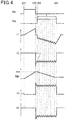
- IGt represents an input state of the ignition signal IGt using the high level or the low level.
- IGw represents an input state of the ignition signal IGt using the high level or the low level.
- I1 " and “V1” represent the primary current (i.e., the value of current flowing through the primary coil 2) and the primary voltage (i.e., the value of voltage applied to the primary coil 2), respectively.
- I2” and “V2” represent the secondary current (i.e., the value of current flowing through the secondary coil 3) and the secondary voltage (i.e., the value of voltage applied to secondary coil 3), respectively.
- Vdc represents energy stored in the capacitor 26 in terms of voltage.
- the first switch 22 When the ignition signal IGt is changed from the low level to the high level at time t01 , the first switch 22 is kept on for which the ignition signal IGt is in the high level, thereby producing a flow of the positive primary current, so that the energy is accumulated in the primary coil 2.
- the step-up switch 28 is turned on and off cyclically to store the step-upped energy in the capacitor 26.
- the first switch 22 is turned off, thereby deenergizing the primary coil 2.
- This causes the secondary coil 3 to develop high voltage through electromagnetic induction, thereby creating the main spark-ignition in the spark plug 5.
- the secondary current is damped in the form of a triangular wave (see a broken line of I2 ).
- the discharge-continuing signal IGw is changed from the low level to the high level at time t03 before the secondary current reaches the threshold value of the lower limit
- the second switch 24 When the discharge-continuing signal IGw has been changed from the low level to the high level, the second switch 24 is turned on and off cyclically, thereby delivering or inputting the energy, as stored in the capacitor 26, to the negative side of the primary coil 2.
- the primary current flows from the primary coil 2 to the positive terminal of the battery 21. More specifically, each time the second switch 24 is turned on, the primary current is additionally delivered from the primary coil 2 toward the positive terminal of the battery 21, so that the primary current increases, in sequence, toward the negative side (see time t03 to time t04 ) .
- the secondary current which is oriented in the same direction as that in which the secondary current flows to create the main spark-ignition is sequentially added to the secondary coil 3, so that the secondary current is kept between the upper and lower limits.
- the second switch 24 is sequentially turned on and off, thereby causing the secondary current to continue to flow with a degree which maintains the discharge of sparks. This causes the continuing spark discharge to be achieved in the spark plug 5 as long as the discharge-continuing signal IGw is in the on-state.
- the ECU 14 stores therein a command value indicating a target value E * of an input amount E of energy delivered by the second circuit 12 in each combustion cycle and a command value indicating the secondary current I2 .
- the ECU 14 determines an energy input duration r in which the energy is delivered by the second circuit 12 based on the command values of the target value E * of the input amount E and the secondary current I2 and then continues to output the discharge-continuing signal IGw for a period of time that is the energy input duration ⁇ .
- the ECU 14 working as the control portion 13 calculates the length of a discharge path 38 (which will also be referred to as a path length L ) between the electrodes of the spark plug 5 in a period of time for which the discharge-continuing signal IGw is outputted, and also calculates a time-sequential change rate ⁇ L / ⁇ t.
- the ECU 14 has a threshold value of the path length L (which will also be referred to below as a first threshold value ⁇ 1 ) and a threshold value of the time-sequential change rate ⁇ L / ⁇ t (which will also be referred to below as a second threshold value ⁇ 2 ).
- the ECU 14 operates the second circuit 12 in two control modes: a normal mode and a special mode.
- the normal mode is a mode entered when the calculated value of the path length L is greater than the first threshold value ⁇ 1 , and the calculated value of the time-sequential change rate ⁇ L / ⁇ t is greater than the second threshold value ⁇ 2 .
- the special mode is a mode entered when the calculated value of the path length L is smaller than the first threshold value ⁇ 1 or the calculated value of the time-sequential change rate ⁇ L / ⁇ t is smaller than the second threshold value ⁇ 2 .
- the ECU 14 monitors the path length L and the time-sequential change rate ⁇ L / ⁇ t in the form of determinations using the threshold values for a period of time in which the energy is delivered by the second circuit 12.
- the ECU 14 determines that the ignition is expected to be delayed and then enters the special mode to increase the target value E * in order to control the delay of the ignition.
- the determination of whether the special mode should be entered or not, that is, whether there is a high probability that the ignition will be delayed or not is made after a lapse of a given period of time since the energy was delivered by the second circuit.
- An increment ⁇ E1 in the target value E * may be determined in various ways.
- the increment ⁇ E1 may be set constant or variable.
- the increment ⁇ E1 may be increased with a decrease in calculated value of the path length L when the special mode is entered as a result of a determination about the path length L using the threshold value.
- the increment ⁇ E1 may also be increased with a decrease in calculated value of the time-sequential change rate ⁇ L / ⁇ t when the special mode is entered as a result of a determination about the time-sequential change rate ⁇ L / ⁇ t using the threshold value.
- the value of the path length L is calculated using, for example, the resistance value of the discharge path 38, an in-cylinder flow velocity v that is a rate of flow in the cylinder 7 of the internal combustion engine 6, a cylinder pressure P that is the pressure in the cylinder 7 of the internal combustion engine 6, and the air-fuel ratio AFR .
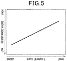
- the ECU 14 calculates the resistance value of the discharge path 38 using detected values of the secondary voltage and the secondary current and then determines the value of the path length L using a correlation between experimentally derived values of the resistance value and values of the path length L (see Fig. 5 ).
- the ECU 14 also corrects the determined value of the path length L using the in-cylinder flow velocity v , the cylinder pressure P , and the air-fuel ratio AFR and determines it as the calculated value of the path length L.
- the value of the in-cylinder flow velocity v is calculated using the speed, as derived by the rotational speed sensor 17.
- the value of the cylinder pressure P is calculated using, for example, the value of the intake pressure, as derived by the intake pressure sensor 18.
- the value of the air-fuel ratio AFR is calculated using an output of the air-fuel ratio sensor 19.
- the correction of the path length L using the in-cylinder flow velocity v , the cylinder pressure P , and the air-fuel ratio AFR is made using mapped data experimentally derived.
- the ECU 14 After entering the special mode, the ECU 14 monitors a short circuit of the discharge path 38 (see Figs. 3(c) , 6(b), and 6(c) ). Specifically, after the special mode is entered, the ECU 14 determines whether the short has occurred or not which will be described later in detail. When determining the short has occurred, the ECU 14 greatly increases the target value E *.
- the greater increment in the target value E* may be determined in various ways.
- the greater increment may be set constant or variable.
- the greater increment may be increased with an increase in change in path length L arising from the short circuit (see Fig. 6(b) ) or an increase in change in time-sequential change rate ⁇ L / ⁇ t resulting from the short circuit.
- the greater increment is increased with an increase in difference or ratio between values of the path length L before and after the short circuit occurs or an increase in difference or ratio between values of the time-sequential change rate ⁇ L / ⁇ t before and after the short circuit occurs.
- increment ⁇ E2 a portion of the greater increment which is calculated as a function of a change in the path length L resulting from the short circuit.
- increment ⁇ E3 A portion of the greater increment which is calculated as a function of a change in the time-sequential change rate ⁇ L / ⁇ t resulting from the short circuit will be referred to as an increment ⁇ E3.
- the ECU 14 When determining that the short circuit has occurred, the ECU 14 also temporarily stops the energy input achieved by the second circuit 12 and then determines whether the discharge of a spark should be resumed by the first circuit 11 or not. This is because when the path length L is kept short without being increased (see Fig. 6(c) ), or a surface spark occurs (see Fig. 3(d) ) after the short circuit occurs, it will result in a great delay in the ignition. It is preferable that the ECU 14 stops the delivery of energy by the second circuit 12 and then resumes the discharge of sparks using the first circuit 11. The ECU 14 uses the following decision criterion to determine whether the discharge is required to be resumed or not.
- the ECU 14 has a threshold value (which will also be referred to as a third threshold value ⁇ 3) for the time of first occurrence of the short circuit, a threshold value (which will also be referred to as a fourth threshold value ⁇ 4) for the time-sequential change rate ⁇ L / ⁇ t after the short circuit occurs for the first time, and a threshold value (which will also be referred to as a fifth threshold value ⁇ 5) for a spark-to-spark interval between the first occurrence of the short circuit and the following occurrence of the short circuit.
- a threshold value which will also be referred to as a third threshold value ⁇ 3
- a threshold value (which will also be referred to as a fourth threshold value ⁇ 4) for the time-sequential change rate ⁇ L / ⁇ t after the short circuit occurs for the first time
- a threshold value (which will also be referred to as a fifth threshold value ⁇ 5) for a spark-to-spark interval between the first occurrence of
- the ECU 14 concludes that the resumption of a discharge of parks is needed, stops the delivery of energy by the second circuit 12, and then operates the first circuit 11 to create the main spark to resume the spark discharge.
- the determination of whether the short circuit has occurred or not is made using detected values of the secondary voltage and the secondary current.
- the ECU 14 has a threshold value (which will also be referred to as a sixth threshold value ⁇ 6) for the secondary voltage, a threshold value (which will also be referred to as a seventh threshold value ⁇ 7) for the secondary current, and a threshold value (which will also be referred to as an eighth threshold value ⁇ 8) for the time-sequential change rate ⁇ V2 / ⁇ t of the secondary voltage.
- a threshold value which will also be referred to as a sixth threshold value ⁇ 6
- a threshold value which will also be referred to as a seventh threshold value ⁇ 7
- an eighth threshold value ⁇ 8 for the time-sequential change rate ⁇ V2 / ⁇ t of the secondary voltage.
- the ECU 14 determines, as the time of occurrence of the short circuit, the time when a detected value of the secondary voltage is lower than or equal to the sixth threshold value ⁇ 6, a detected value of the secondary current is lower than or equal to the seventh threshold value ⁇ 7, and the time-sequential change rate ⁇ V2 / ⁇ t of the secondary voltage becomes greater than or equal to the eighth threshold value ⁇ 8.
- the ECU 14 When no short circuit has occurred after the special mode is entered, the ECU 14 adds the increment ⁇ E1 to the initial target value E * to update the target value E * and then controls the operation of the second circuit 12 using the updated target value E *. When the short circuit has occurred after the special mode is entered, the ECU 14 also adds the increments ⁇ E1, ⁇ E2, and ⁇ E3 to the initial target value E* to update the target value E *, and then controls the operation of the second circuit 12 using the updated target value E *.
- the ECU 14 prolongs the energy input duration ⁇ or increases the command value of the secondary current I2 based on a last derived value of the target value E * to substantially increase the energy input amount E .
- the value of the secondary voltage is, as described above, fed back to the ECU 14.
- the ECU 14 may, therefore, be designed to determine the command value for the secondary voltage and then increase the command value of the secondary voltage V2 based on the increased target value E *, thereby substantially increasing the energy input amount E .
- the initial target value E * before the energy input amount E is increased is given by an initial value E0 stored in the ECU 14.
- the initial value E0 continues to be used as the target value E * without increasing the target value E *.
- the initial value E0 may be updated as the increased target value E * (i.e., E0 + ⁇ E1 or E0 + ⁇ E1 + ⁇ E2 + ⁇ E3 ).
- the ECU 14 may execute the ignition for several cycles using the updated initial value E0 , and measure a variation in torque, and update the initial value E0 again as a function of the variation in torque. For instance, when the variation in torque is lower than a given value, the initial value E0 may be set to be low, while when the variation in torque is greater than the given value, the initial value E0 may be set to be high.
- step S1 the discharge of a spark is initiated. Specifically, the output of the ignition signal IGt is started and then stopped, thereby initiating the discharge of a spark using the first circuit 11 to achieve the main spark-ignition. Subsequently, the output of the discharge-continuing signal IGw is started to start delivering the energy using the second circuit 12 to continue the discharge of sparks.
- the ECU 14 starts monitoring the path length L and the time-sequential change rate ⁇ L / ⁇ t at the same time as when the output of the discharge-continuing signal IGw is started.
- step S2 it is determined whether there is a high probability that the ignition is delayed or not. This determination is started after a lapse of a given period of time following the start of output of the discharge-continuing signal IGw. If one of two conditions where the calculated value of the path length L is smaller than the first threshold value ⁇ 1 and where the calculated value of the time-sequential change rate ⁇ L / ⁇ t is smaller than the second threshold value ⁇ 2 is met, it is determined that there is a high risk that the ignition is delayed. If the two conditions are not met, it is determined that the risk that the ignition is delay is low.
- step S3 the special mode that is the control mode of the second circuit 12 is selected.
- step S4 the normal mode is selected.
- step S5 NO answer is obtained until the energy input duration ⁇ passes, that is, the delivery of energy using the second circuit 12 is continued to maintain the continuing spark discharge.
- step S3 wherein the special mode is selected, the routine proceeds to step S6 wherein the increment ⁇ E1 is calculated and added to the target value E *. How to calculate the increment ⁇ E1 has already been described. The routine then proceeds to step S7 wherein the updated target value E * is used to re-calculate the energy input duration ⁇ . The second circuit 12 then continues to deliver the energy using the re-calculated energy input duration ⁇ .
- step S8 in the special mode wherein it is determined whether the discharge of a spark is short-circuited or not. The determination of whether the short circuit has occurred or not is made in the way as described above. If it is determined that the short circuit has not occurred (NO), then the routine proceeds to step S9 wherein NO answer is obtained until the energy input duration ⁇ passes. The determination of whether the short circuit has occurred or not in step S8 is continued.
- step S10 the routine proceeds to step S10 wherein the increments ⁇ E2 and ⁇ E3 are calculated and added to the target value E *.
- the calculation of the increments ⁇ E2 and ⁇ E3 is made in the way as described above.
- the routine then proceeds to step S11 wherein the energy input duration ⁇ is re-calculated using the updated target value E *.
- the second circuit 12 then continues to deliver the energy using the re-calculated energy input duration ⁇ .
- step S12 in the special mode wherein it is determined whether the spark discharge has been short-circuited again or not. If it is determined that the short circuit has not occurred again (NO), then the routine proceeds to step S13 wherein the determination of whether the short circuit has occurred or not is continued, that is, the determination in step S12 is continued until the energy input duration ⁇ passes.
- step S14 the routine proceeds to step S14 wherein the resumption of a discharge is needed or not.
- the determination of whether it is necessary to re-discharge a spark or not is made in the way as described above. If the re-discharge is not needed (NO), then the routine proceeds to step S 15 wherein the determination in step S 14 as to whether the re-discharge is needed or not is made until the energy input duration ⁇ passes.
- step S16 the ECU 14 stops the second circuit 12 from delivering the energy to temporarily terminate the spark discharge and then returns back to step S1 to resume a discharge of a spark.
- step S5 If it is determined (YES) in step S5, S9, S13, or S15 that the energy input duration ⁇ has passed, then the routine proceeds to step S17 wherein the ECU 14 stops the second circuit 12 from delivery the energy to terminate the spark discharge. The routine then proceeds to step S18 wherein the initial value E0 is updated as the increased target value E *(i.e., E0 + ⁇ E1 or E0 + ⁇ E1 + ⁇ E2 + ⁇ E3 ) .
- the ignition apparatus 1 of the embodiment has the ECU 14 which monitors the path length L and the time-sequential change rate ⁇ L / ⁇ t using the threshold values for a period of time in which the second circuit 12 delivers the energy to the spark plug 5.
- the ECU 14 determines that the ignition is expected to be delayed and then enters the special mode to increase the target value E * in order to control the delay of the ignition.
- This embodiment focuses on the fact that the variation in ignition, especially, the delay of the ignition is caused by a decrease in the path length L .
- the ignition is achieved by extension of a spark by a gas flow in the cylinder 7, thereby prolonging the path length L. Therefore, when the path length L is short, there is a risk that the ignition is delayed.
- this embodiment monitors the path length L and the time-sequential change rate ⁇ L / ⁇ t in the form of threshold determinations.
- the special mode is selected to increase the energy input amount E using the second circuit 12. This minimizes the delay of the ignition caused by the fact that the path length L does not become long.
- the ignition apparatus 1 designed to use the second circuit 12 in continuing the spark discharge is, therefore, capable of decreasing the variation in ignition without increasing the energy input amount E .
- the energy input amount E is increased using the second circuit 12 with an increase in variation in the time-sequential change rate ⁇ L / ⁇ t resulting from the occurrence of the short circuit.
- This enables an increase in the energy input amount E required to decrease the variation in the ignition to be properly regulated.
- the smaller a ratio or difference in the time-sequential change rate ⁇ L / ⁇ t before and after the short circuit occurs the smaller the energy input amount E required to eliminate the delay of the ignition (see Fig. 8(a) ).
- the histogram in Fig. 8(a) represents the energy input amount E which is required to eliminate the delay of the ignition and quantified when the ignition delay/the energy input amount E becomes lower than a given threshold value.
- the energy input amount E is increased with an increase in variation in the time-sequential change rate ⁇ L / ⁇ t arising from the occurrence of a short circuit, thereby properly regulating an amount by which the energy input amount E is required to be increased to decrease the variation in the ignition, which minimizes an excess of the input energy. For instance, as compared with the case where the energy input amount E which is suitable for a maximum difference in the time-sequential change rate ⁇ L / ⁇ t when the short circuit is occurring is fixed (see a straight horizontal line X1 in Fig.
- an excess of the energy in a range a is decreased by regulating the energy input amount E as a function of a variation in the time-sequential change rate ⁇ L / ⁇ t when the short circuit is occurring.
- the ECU 14 determines whether the second circuit 12 should be stopped from maintaining the continuing spark discharge for determining whether the main spark-ignition should be initiated again by the first circuit 11, that is, whether it is necessary to discharge a spark again or not. This enables a re-discharge to be performed when there is a high risk that the path length L is undesirably kept short, or the surface spark is created, which will lead to a great delay of the ignition, thereby eliminating such a risk.
- the histogram in Fig. 8(b) represents the energy input amount E which is required to eliminate the delay of the ignition and quantified when the ignition delay/the energy input amount E becomes lower than a given threshold value.
- the energy input amount E is increased with an increase in variation in the path length L arising from the short circuit, thereby properly regulating an amount by which the energy input amount E is required to be increased to decrease the variation in the ignition, which minimizes an excess of the input energy.
- an excess of the energy in a range, as enclosed by the straight horizontal line and the histogram is decreased by regulating the energy input amount E as a function of a variation in the time-sequential change rate ⁇ L / ⁇ t when the short circuit is occurring.
- Fig. 9 illustrates a comparison between a conventional apparatus which is equipped with the first and second circuits 11 and 12 and fixes the energy input amount E and the ignition apparatus 1 of this embodiment and shows that the energy input amount E may be decreased. Therefore, the ignition apparatus 1 is capable of decreasing the energy input amount E as compared with the conventional apparatus. When the energy input amount E is the same between the ignition apparatus 1 and the conventional apparatus, the ignition apparatus 1 is capable of decreasing the delay of the ignition as compared with the conventional apparatus.
- the ignition apparatus 1 may be modified in various ways without being limited to the embodiments.
- the ignition apparatus 1 of the embodiment selects the special mode or the normal mode based on the threshold determinations of both the path length L and the time-sequential change rate ⁇ L / ⁇ t, but however, may be designed to select the special mode or the normal mode based on the threshold determination of either of the path length L or the time-sequential change rate ⁇ L / ⁇ t.
- the ignition apparatus 1 of the embodiment calculates the path length L based on the resistance value of the discharge path 38, the in-cylinder flow velocity v , the cylinder pressure P , and the air-fuel ratio AFR , but however, may be designed to have a first detecting portion which detects or calculates electrical physical quantities, such as the secondary voltage and the resistance value of the discharge path 38 and a second detecting portion which detects or calculates physical quantities of intake air or air-fuel mixture, such as the in-cylinder flow velocity v , the cylinder pressure P , and the air-fuel ratio AFR .
- the ignition apparatus may work to use at least one of the physical quantities, as detected or calculated by the first detecting portion, and at least one of the physical quantities, as detected or calculated by the second detecting portion, to determine the path length L .
- the ignition apparatus 1 of the embodiment calculates the in-cylinder flow velocity v based on the detected value of the rotational speed sensor 17 and also calculates the cylinder pressure P based on the detected value of the intake pressure sensor 18, but however, may alternatively be designed to have, as sensors outputting signals to the ECU 14, a flow rate sensor which detects a flow rate of intake air sucked into the cylinder 7 and an intake temperature sensor which detects the temperature of the intake air and to calculate the in-cylinder flow velocity v and the cylinder pressure P using detected values of parameters, as derived by the above sensors.
- the ignition apparatus 1 of the embodiment prolongs the energy input duration ⁇ to increase the energy input amount E , but however, may be designed to increase the command value for the secondary current or the secondary voltage to increase the energy input amount E .
- the embodiment shows an example where the ignition apparatus 1 is used in the gasoline internal combustion engine 6, but may be applied to the internal combustion engine 6 which is designed to use ethanol fuel or blended fuel or may employ a low-quality fuel.
- the embodiment shows an example where the ignition apparatus 1 is applied to the internal combustion engine 6 capable of achieving lean-burn of fuel, but however, is not limited thereto because the continuing spark discharge can be established to improve the ignitability in different status of fuel combustion.
- the ignition apparatus 1 may be used with the internal combustion engine 6 designed not to execute the lean-burn of fuel.
- the embodiment shows an example where the ignition apparatus 1 is applied to the direct injection type of internal combustion engine 6 which inject fuel directly into the cylinder 7, but however, may be used with a port injection type of the internal combustion engine 6 designed to inject fuel into an intake port.
- the embodiment also shows an example where the ignition apparatus 1 is used with the internal combustion engine 6 which actively produces a spiral flow of the mixture in the cylinder 7, but however, may alternatively be used with the internal combustion engine 6 designed not to have a mechanism which actively produces the spiral flow of the mixture in the cylinder 7.
Landscapes
- Engineering & Computer Science (AREA)
- Chemical & Material Sciences (AREA)
- Combustion & Propulsion (AREA)
- Mechanical Engineering (AREA)
- General Engineering & Computer Science (AREA)
- Physics & Mathematics (AREA)
- Plasma & Fusion (AREA)
- Ignition Installations For Internal Combustion Engines (AREA)
Applications Claiming Priority (2)
| Application Number | Priority Date | Filing Date | Title |
|---|---|---|---|
| JP2015100264A JP6489929B2 (ja) | 2015-05-15 | 2015-05-15 | 点火装置 |
| PCT/JP2016/064080 WO2016185988A1 (fr) | 2015-05-15 | 2016-05-12 | Système d'allumage |
Publications (3)
| Publication Number | Publication Date |
|---|---|
| EP3296560A1 true EP3296560A1 (fr) | 2018-03-21 |
| EP3296560A4 EP3296560A4 (fr) | 2019-01-16 |
| EP3296560B1 EP3296560B1 (fr) | 2020-11-04 |
Family
ID=57319950
Family Applications (1)
| Application Number | Title | Priority Date | Filing Date |
|---|---|---|---|
| EP16796381.8A Not-in-force EP3296560B1 (fr) | 2015-05-15 | 2016-05-12 | Dispositif d'allumage |
Country Status (4)
| Country | Link |
|---|---|
| US (1) | US10415533B2 (fr) |
| EP (1) | EP3296560B1 (fr) |
| JP (1) | JP6489929B2 (fr) |
| WO (1) | WO2016185988A1 (fr) |
Families Citing this family (8)
| Publication number | Priority date | Publication date | Assignee | Title |
|---|---|---|---|---|
| JP6377198B1 (ja) * | 2017-04-07 | 2018-08-22 | 三菱電機株式会社 | 内燃機関の制御装置及び制御方法 |
| JP6395905B1 (ja) * | 2017-06-27 | 2018-09-26 | 三菱電機株式会社 | 内燃機関の制御装置及び制御方法 |
| JP6951900B2 (ja) * | 2017-08-04 | 2021-10-20 | 株式会社Soken | 内燃機関用の点火装置 |
| JP6860469B2 (ja) * | 2017-12-13 | 2021-04-14 | 株式会社豊田中央研究所 | 内燃機関の点火装置 |
| JP6698906B1 (ja) * | 2019-04-02 | 2020-05-27 | 三菱電機株式会社 | 内燃機関の放電状態検出装置 |
| JP6735877B1 (ja) | 2019-05-09 | 2020-08-05 | 三菱電機株式会社 | 点火装置 |
| JP7230147B1 (ja) * | 2021-09-24 | 2023-02-28 | エヌ・ティ・ティ・コミュニケーションズ株式会社 | 車両セキュリティ分析装置、方法およびそのプログラム |
| CN118793551A (zh) * | 2024-07-09 | 2024-10-18 | 东风汽车集团股份有限公司 | 点火线圈保护控制方法、存储介质、发动机点火系统和车辆 |
Family Cites Families (6)
| Publication number | Priority date | Publication date | Assignee | Title |
|---|---|---|---|---|
| JP4978737B2 (ja) * | 2010-01-08 | 2012-07-18 | トヨタ自動車株式会社 | 内燃機関の点火制御システム |
| JP5688683B2 (ja) | 2011-07-16 | 2015-03-25 | 株式会社デンソー | 内燃機関の制御装置 |
| US9291142B2 (en) * | 2011-09-14 | 2016-03-22 | Toyota Jidosha Kabushiki Kaisha | Ignition control device for internal combustion engine |
| JP6330366B2 (ja) * | 2013-04-11 | 2018-05-30 | 株式会社デンソー | 点火装置 |
| EP3006725B1 (fr) * | 2013-05-24 | 2020-07-01 | Denso Corporation | Dispositif de commande d'allumage pour moteur à combustion interne |
| JP6206285B2 (ja) * | 2013-09-06 | 2017-10-04 | トヨタ自動車株式会社 | 内燃機関 |
-
2015
- 2015-05-15 JP JP2015100264A patent/JP6489929B2/ja not_active Expired - Fee Related
-
2016
- 2016-05-12 WO PCT/JP2016/064080 patent/WO2016185988A1/fr not_active Ceased
- 2016-05-12 US US15/573,914 patent/US10415533B2/en active Active
- 2016-05-12 EP EP16796381.8A patent/EP3296560B1/fr not_active Not-in-force
Also Published As
| Publication number | Publication date |
|---|---|
| EP3296560B1 (fr) | 2020-11-04 |
| JP6489929B2 (ja) | 2019-03-27 |
| WO2016185988A1 (fr) | 2016-11-24 |
| US10415533B2 (en) | 2019-09-17 |
| JP2016217189A (ja) | 2016-12-22 |
| EP3296560A4 (fr) | 2019-01-16 |
| US20180266381A1 (en) | 2018-09-20 |
Similar Documents
| Publication | Publication Date | Title |
|---|---|---|
| EP3296560B1 (fr) | Dispositif d'allumage | |
| US7404396B2 (en) | Multiple discharge ignition control apparatus and method for internal combustion engines | |
| JP6274056B2 (ja) | 点火装置 | |
| US20080184968A1 (en) | Solenoid valve driver and fuel injection system equipped with the same for compensating lag of operation of solenoid valve | |
| CN106170623B (zh) | 内燃机用点火装置 | |
| EP3296561B1 (fr) | Dispositif d'allumage | |
| JP6610073B2 (ja) | 点火装置 | |
| JP6549901B2 (ja) | 点火装置 | |
| EP3172423B1 (fr) | Procédé de détection d'une défaillance d'un capteur de rapport air-carburant | |
| JP6392535B2 (ja) | 内燃機関の制御装置 | |
| JP6349895B2 (ja) | 内燃機関用点火装置 | |
| WO2015146126A1 (fr) | Dispositif de commande d'allumage de moteur | |
| US10138861B2 (en) | Ignition device | |
| JP6297899B2 (ja) | 点火装置 | |
| JP2015200255A (ja) | 点火制御装置 | |
| JP3511353B2 (ja) | 燃料ポンプ制御装置 | |
| JP6451876B2 (ja) | 点火装置 | |
| JP6411951B2 (ja) | 内燃機関の制御装置 | |
| JP6426365B2 (ja) | 内燃機関の点火制御装置 | |
| JP4781454B2 (ja) | 内燃機関制御装置 | |
| JP2018119499A (ja) | 内燃機関制御装置及び内燃機関システム | |
| JPH04298662A (ja) | エンジンのアイドル回転数制御装置 |
Legal Events
| Date | Code | Title | Description |
|---|---|---|---|
| STAA | Information on the status of an ep patent application or granted ep patent |
Free format text: STATUS: THE INTERNATIONAL PUBLICATION HAS BEEN MADE |
|
| PUAI | Public reference made under article 153(3) epc to a published international application that has entered the european phase |
Free format text: ORIGINAL CODE: 0009012 |
|
| STAA | Information on the status of an ep patent application or granted ep patent |
Free format text: STATUS: REQUEST FOR EXAMINATION WAS MADE |
|
| 17P | Request for examination filed |
Effective date: 20171205 |
|
| AK | Designated contracting states |
Kind code of ref document: A1 Designated state(s): AL AT BE BG CH CY CZ DE DK EE ES FI FR GB GR HR HU IE IS IT LI LT LU LV MC MK MT NL NO PL PT RO RS SE SI SK SM TR |
|
| AX | Request for extension of the european patent |
Extension state: BA ME |
|
| TPAC | Observations filed by third parties |
Free format text: ORIGINAL CODE: EPIDOSNTIPA |
|
| DAV | Request for validation of the european patent (deleted) | ||
| DAX | Request for extension of the european patent (deleted) | ||
| A4 | Supplementary search report drawn up and despatched |
Effective date: 20181219 |
|
| RIC1 | Information provided on ipc code assigned before grant |
Ipc: F02P 3/08 20060101ALN20181213BHEP Ipc: F02D 35/02 20060101ALN20181213BHEP Ipc: F02P 3/00 20060101AFI20181213BHEP Ipc: F02P 17/12 20060101ALI20181213BHEP Ipc: F02P 3/04 20060101ALN20181213BHEP Ipc: F02P 3/05 20060101ALI20181213BHEP Ipc: F02P 9/00 20060101ALI20181213BHEP Ipc: H01T 13/58 20110101ALI20181213BHEP Ipc: F02D 41/14 20060101ALN20181213BHEP Ipc: F02P 15/10 20060101ALI20181213BHEP |
|
| STAA | Information on the status of an ep patent application or granted ep patent |
Free format text: STATUS: EXAMINATION IS IN PROGRESS |
|
| 17Q | First examination report despatched |
Effective date: 20190129 |
|
| GRAP | Despatch of communication of intention to grant a patent |
Free format text: ORIGINAL CODE: EPIDOSNIGR1 |
|
| STAA | Information on the status of an ep patent application or granted ep patent |
Free format text: STATUS: GRANT OF PATENT IS INTENDED |
|
| RIC1 | Information provided on ipc code assigned before grant |
Ipc: F02P 3/00 20060101AFI20200430BHEP Ipc: F02D 35/02 20060101ALN20200430BHEP Ipc: F02P 3/04 20060101ALN20200430BHEP Ipc: F02P 3/05 20060101ALI20200430BHEP Ipc: F02P 9/00 20060101ALI20200430BHEP Ipc: F02D 41/14 20060101ALN20200430BHEP Ipc: F02P 3/08 20060101ALN20200430BHEP Ipc: H01T 13/58 20200101ALI20200430BHEP Ipc: F02P 15/10 20060101ALI20200430BHEP Ipc: F02P 17/12 20060101ALI20200430BHEP |
|
| INTG | Intention to grant announced |
Effective date: 20200519 |
|
| GRAS | Grant fee paid |
Free format text: ORIGINAL CODE: EPIDOSNIGR3 |
|
| GRAA | (expected) grant |
Free format text: ORIGINAL CODE: 0009210 |
|
| STAA | Information on the status of an ep patent application or granted ep patent |
Free format text: STATUS: THE PATENT HAS BEEN GRANTED |
|
| AK | Designated contracting states |
Kind code of ref document: B1 Designated state(s): AL AT BE BG CH CY CZ DE DK EE ES FI FR GB GR HR HU IE IS IT LI LT LU LV MC MK MT NL NO PL PT RO RS SE SI SK SM TR |
|
| REG | Reference to a national code |
Ref country code: GB Ref legal event code: FG4D |
|
| REG | Reference to a national code |
Ref country code: CH Ref legal event code: EP |
|
| REG | Reference to a national code |
Ref country code: AT Ref legal event code: REF Ref document number: 1331129 Country of ref document: AT Kind code of ref document: T Effective date: 20201115 |
|
| REG | Reference to a national code |
Ref country code: IE Ref legal event code: FG4D |
|
| REG | Reference to a national code |
Ref country code: DE Ref legal event code: R096 Ref document number: 602016047298 Country of ref document: DE |
|
| REG | Reference to a national code |
Ref country code: NL Ref legal event code: MP Effective date: 20201104 |
|
| REG | Reference to a national code |
Ref country code: AT Ref legal event code: MK05 Ref document number: 1331129 Country of ref document: AT Kind code of ref document: T Effective date: 20201104 |
|
| PG25 | Lapsed in a contracting state [announced via postgrant information from national office to epo] |
Ref country code: FI Free format text: LAPSE BECAUSE OF FAILURE TO SUBMIT A TRANSLATION OF THE DESCRIPTION OR TO PAY THE FEE WITHIN THE PRESCRIBED TIME-LIMIT Effective date: 20201104 Ref country code: GR Free format text: LAPSE BECAUSE OF FAILURE TO SUBMIT A TRANSLATION OF THE DESCRIPTION OR TO PAY THE FEE WITHIN THE PRESCRIBED TIME-LIMIT Effective date: 20210205 Ref country code: NO Free format text: LAPSE BECAUSE OF FAILURE TO SUBMIT A TRANSLATION OF THE DESCRIPTION OR TO PAY THE FEE WITHIN THE PRESCRIBED TIME-LIMIT Effective date: 20210204 Ref country code: PT Free format text: LAPSE BECAUSE OF FAILURE TO SUBMIT A TRANSLATION OF THE DESCRIPTION OR TO PAY THE FEE WITHIN THE PRESCRIBED TIME-LIMIT Effective date: 20210304 Ref country code: RS Free format text: LAPSE BECAUSE OF FAILURE TO SUBMIT A TRANSLATION OF THE DESCRIPTION OR TO PAY THE FEE WITHIN THE PRESCRIBED TIME-LIMIT Effective date: 20201104 |
|
| PG25 | Lapsed in a contracting state [announced via postgrant information from national office to epo] |
Ref country code: IS Free format text: LAPSE BECAUSE OF FAILURE TO SUBMIT A TRANSLATION OF THE DESCRIPTION OR TO PAY THE FEE WITHIN THE PRESCRIBED TIME-LIMIT Effective date: 20210304 Ref country code: LV Free format text: LAPSE BECAUSE OF FAILURE TO SUBMIT A TRANSLATION OF THE DESCRIPTION OR TO PAY THE FEE WITHIN THE PRESCRIBED TIME-LIMIT Effective date: 20201104 Ref country code: PL Free format text: LAPSE BECAUSE OF FAILURE TO SUBMIT A TRANSLATION OF THE DESCRIPTION OR TO PAY THE FEE WITHIN THE PRESCRIBED TIME-LIMIT Effective date: 20201104 Ref country code: BG Free format text: LAPSE BECAUSE OF FAILURE TO SUBMIT A TRANSLATION OF THE DESCRIPTION OR TO PAY THE FEE WITHIN THE PRESCRIBED TIME-LIMIT Effective date: 20210204 Ref country code: ES Free format text: LAPSE BECAUSE OF FAILURE TO SUBMIT A TRANSLATION OF THE DESCRIPTION OR TO PAY THE FEE WITHIN THE PRESCRIBED TIME-LIMIT Effective date: 20201104 Ref country code: AT Free format text: LAPSE BECAUSE OF FAILURE TO SUBMIT A TRANSLATION OF THE DESCRIPTION OR TO PAY THE FEE WITHIN THE PRESCRIBED TIME-LIMIT Effective date: 20201104 Ref country code: SE Free format text: LAPSE BECAUSE OF FAILURE TO SUBMIT A TRANSLATION OF THE DESCRIPTION OR TO PAY THE FEE WITHIN THE PRESCRIBED TIME-LIMIT Effective date: 20201104 |
|
| REG | Reference to a national code |
Ref country code: LT Ref legal event code: MG9D |
|
| PG25 | Lapsed in a contracting state [announced via postgrant information from national office to epo] |
Ref country code: HR Free format text: LAPSE BECAUSE OF FAILURE TO SUBMIT A TRANSLATION OF THE DESCRIPTION OR TO PAY THE FEE WITHIN THE PRESCRIBED TIME-LIMIT Effective date: 20201104 |
|
| PG25 | Lapsed in a contracting state [announced via postgrant information from national office to epo] |
Ref country code: RO Free format text: LAPSE BECAUSE OF FAILURE TO SUBMIT A TRANSLATION OF THE DESCRIPTION OR TO PAY THE FEE WITHIN THE PRESCRIBED TIME-LIMIT Effective date: 20201104 Ref country code: SK Free format text: LAPSE BECAUSE OF FAILURE TO SUBMIT A TRANSLATION OF THE DESCRIPTION OR TO PAY THE FEE WITHIN THE PRESCRIBED TIME-LIMIT Effective date: 20201104 Ref country code: LT Free format text: LAPSE BECAUSE OF FAILURE TO SUBMIT A TRANSLATION OF THE DESCRIPTION OR TO PAY THE FEE WITHIN THE PRESCRIBED TIME-LIMIT Effective date: 20201104 Ref country code: SM Free format text: LAPSE BECAUSE OF FAILURE TO SUBMIT A TRANSLATION OF THE DESCRIPTION OR TO PAY THE FEE WITHIN THE PRESCRIBED TIME-LIMIT Effective date: 20201104 Ref country code: EE Free format text: LAPSE BECAUSE OF FAILURE TO SUBMIT A TRANSLATION OF THE DESCRIPTION OR TO PAY THE FEE WITHIN THE PRESCRIBED TIME-LIMIT Effective date: 20201104 Ref country code: CZ Free format text: LAPSE BECAUSE OF FAILURE TO SUBMIT A TRANSLATION OF THE DESCRIPTION OR TO PAY THE FEE WITHIN THE PRESCRIBED TIME-LIMIT Effective date: 20201104 |
|
| REG | Reference to a national code |
Ref country code: DE Ref legal event code: R097 Ref document number: 602016047298 Country of ref document: DE |
|
| PG25 | Lapsed in a contracting state [announced via postgrant information from national office to epo] |
Ref country code: DK Free format text: LAPSE BECAUSE OF FAILURE TO SUBMIT A TRANSLATION OF THE DESCRIPTION OR TO PAY THE FEE WITHIN THE PRESCRIBED TIME-LIMIT Effective date: 20201104 |
|
| PLBE | No opposition filed within time limit |
Free format text: ORIGINAL CODE: 0009261 |
|
| STAA | Information on the status of an ep patent application or granted ep patent |
Free format text: STATUS: NO OPPOSITION FILED WITHIN TIME LIMIT |
|
| 26N | No opposition filed |
Effective date: 20210805 |
|
| PG25 | Lapsed in a contracting state [announced via postgrant information from national office to epo] |
Ref country code: NL Free format text: LAPSE BECAUSE OF FAILURE TO SUBMIT A TRANSLATION OF THE DESCRIPTION OR TO PAY THE FEE WITHIN THE PRESCRIBED TIME-LIMIT Effective date: 20201104 Ref country code: AL Free format text: LAPSE BECAUSE OF FAILURE TO SUBMIT A TRANSLATION OF THE DESCRIPTION OR TO PAY THE FEE WITHIN THE PRESCRIBED TIME-LIMIT Effective date: 20201104 Ref country code: IT Free format text: LAPSE BECAUSE OF FAILURE TO SUBMIT A TRANSLATION OF THE DESCRIPTION OR TO PAY THE FEE WITHIN THE PRESCRIBED TIME-LIMIT Effective date: 20201104 |
|
| PG25 | Lapsed in a contracting state [announced via postgrant information from national office to epo] |
Ref country code: SI Free format text: LAPSE BECAUSE OF FAILURE TO SUBMIT A TRANSLATION OF THE DESCRIPTION OR TO PAY THE FEE WITHIN THE PRESCRIBED TIME-LIMIT Effective date: 20201104 |
|
| REG | Reference to a national code |
Ref country code: CH Ref legal event code: PL |
|
| GBPC | Gb: european patent ceased through non-payment of renewal fee |
Effective date: 20210512 |
|
| PG25 | Lapsed in a contracting state [announced via postgrant information from national office to epo] |
Ref country code: CH Free format text: LAPSE BECAUSE OF NON-PAYMENT OF DUE FEES Effective date: 20210531 Ref country code: MC Free format text: LAPSE BECAUSE OF FAILURE TO SUBMIT A TRANSLATION OF THE DESCRIPTION OR TO PAY THE FEE WITHIN THE PRESCRIBED TIME-LIMIT Effective date: 20201104 Ref country code: LI Free format text: LAPSE BECAUSE OF NON-PAYMENT OF DUE FEES Effective date: 20210531 Ref country code: LU Free format text: LAPSE BECAUSE OF NON-PAYMENT OF DUE FEES Effective date: 20210512 |
|
| REG | Reference to a national code |
Ref country code: BE Ref legal event code: MM Effective date: 20210531 |
|
| PG25 | Lapsed in a contracting state [announced via postgrant information from national office to epo] |
Ref country code: IE Free format text: LAPSE BECAUSE OF NON-PAYMENT OF DUE FEES Effective date: 20210512 Ref country code: GB Free format text: LAPSE BECAUSE OF NON-PAYMENT OF DUE FEES Effective date: 20210512 |
|
| PG25 | Lapsed in a contracting state [announced via postgrant information from national office to epo] |
Ref country code: IS Free format text: LAPSE BECAUSE OF FAILURE TO SUBMIT A TRANSLATION OF THE DESCRIPTION OR TO PAY THE FEE WITHIN THE PRESCRIBED TIME-LIMIT Effective date: 20210304 |
|
| PG25 | Lapsed in a contracting state [announced via postgrant information from national office to epo] |
Ref country code: BE Free format text: LAPSE BECAUSE OF NON-PAYMENT OF DUE FEES Effective date: 20210531 |
|
| PG25 | Lapsed in a contracting state [announced via postgrant information from national office to epo] |
Ref country code: HU Free format text: LAPSE BECAUSE OF FAILURE TO SUBMIT A TRANSLATION OF THE DESCRIPTION OR TO PAY THE FEE WITHIN THE PRESCRIBED TIME-LIMIT; INVALID AB INITIO Effective date: 20160512 |
|
| PG25 | Lapsed in a contracting state [announced via postgrant information from national office to epo] |
Ref country code: CY Free format text: LAPSE BECAUSE OF FAILURE TO SUBMIT A TRANSLATION OF THE DESCRIPTION OR TO PAY THE FEE WITHIN THE PRESCRIBED TIME-LIMIT Effective date: 20201104 |
|
| PGFP | Annual fee paid to national office [announced via postgrant information from national office to epo] |
Ref country code: FR Payment date: 20230526 Year of fee payment: 8 Ref country code: DE Payment date: 20230519 Year of fee payment: 8 |
|
| PG25 | Lapsed in a contracting state [announced via postgrant information from national office to epo] |
Ref country code: MK Free format text: LAPSE BECAUSE OF FAILURE TO SUBMIT A TRANSLATION OF THE DESCRIPTION OR TO PAY THE FEE WITHIN THE PRESCRIBED TIME-LIMIT Effective date: 20201104 |
|
| PG25 | Lapsed in a contracting state [announced via postgrant information from national office to epo] |
Ref country code: MT Free format text: LAPSE BECAUSE OF FAILURE TO SUBMIT A TRANSLATION OF THE DESCRIPTION OR TO PAY THE FEE WITHIN THE PRESCRIBED TIME-LIMIT Effective date: 20201104 |
|
| REG | Reference to a national code |
Ref country code: DE Ref legal event code: R119 Ref document number: 602016047298 Country of ref document: DE |
|
| PG25 | Lapsed in a contracting state [announced via postgrant information from national office to epo] |
Ref country code: DE Free format text: LAPSE BECAUSE OF NON-PAYMENT OF DUE FEES Effective date: 20241203 |
|
| PG25 | Lapsed in a contracting state [announced via postgrant information from national office to epo] |
Ref country code: FR Free format text: LAPSE BECAUSE OF NON-PAYMENT OF DUE FEES Effective date: 20240531 |
|
| PG25 | Lapsed in a contracting state [announced via postgrant information from national office to epo] |
Ref country code: TR Free format text: LAPSE BECAUSE OF FAILURE TO SUBMIT A TRANSLATION OF THE DESCRIPTION OR TO PAY THE FEE WITHIN THE PRESCRIBED TIME-LIMIT Effective date: 20201104 |