EP3296563A1 - Turbine éolienne et procédé et dispositif de commande de fonctionnement pour cette dernière - Google Patents
Turbine éolienne et procédé et dispositif de commande de fonctionnement pour cette dernière Download PDFInfo
- Publication number
- EP3296563A1 EP3296563A1 EP17785283.7A EP17785283A EP3296563A1 EP 3296563 A1 EP3296563 A1 EP 3296563A1 EP 17785283 A EP17785283 A EP 17785283A EP 3296563 A1 EP3296563 A1 EP 3296563A1
- Authority
- EP
- European Patent Office
- Prior art keywords
- wind turbine
- wind
- current
- turbine
- predetermined
- Prior art date
- Legal status (The legal status is an assumption and is not a legal conclusion. Google has not performed a legal analysis and makes no representation as to the accuracy of the status listed.)
- Granted
Links
Images



Classifications
-
- F—MECHANICAL ENGINEERING; LIGHTING; HEATING; WEAPONS; BLASTING
- F03—MACHINES OR ENGINES FOR LIQUIDS; WIND, SPRING, OR WEIGHT MOTORS; PRODUCING MECHANICAL POWER OR A REACTIVE PROPULSIVE THRUST, NOT OTHERWISE PROVIDED FOR
- F03D—WIND MOTORS
- F03D7/00—Controlling wind motors
- F03D7/02—Controlling wind motors the wind motors having rotation axis substantially parallel to the air flow entering the rotor
-
- F—MECHANICAL ENGINEERING; LIGHTING; HEATING; WEAPONS; BLASTING
- F03—MACHINES OR ENGINES FOR LIQUIDS; WIND, SPRING, OR WEIGHT MOTORS; PRODUCING MECHANICAL POWER OR A REACTIVE PROPULSIVE THRUST, NOT OTHERWISE PROVIDED FOR
- F03D—WIND MOTORS
- F03D7/00—Controlling wind motors
-
- F—MECHANICAL ENGINEERING; LIGHTING; HEATING; WEAPONS; BLASTING
- F03—MACHINES OR ENGINES FOR LIQUIDS; WIND, SPRING, OR WEIGHT MOTORS; PRODUCING MECHANICAL POWER OR A REACTIVE PROPULSIVE THRUST, NOT OTHERWISE PROVIDED FOR
- F03D—WIND MOTORS
- F03D7/00—Controlling wind motors
- F03D7/02—Controlling wind motors the wind motors having rotation axis substantially parallel to the air flow entering the rotor
- F03D7/04—Automatic control; Regulation
- F03D7/042—Automatic control; Regulation by means of an electrical or electronic controller
- F03D7/048—Automatic control; Regulation by means of an electrical or electronic controller controlling wind farms
-
- F—MECHANICAL ENGINEERING; LIGHTING; HEATING; WEAPONS; BLASTING
- F03—MACHINES OR ENGINES FOR LIQUIDS; WIND, SPRING, OR WEIGHT MOTORS; PRODUCING MECHANICAL POWER OR A REACTIVE PROPULSIVE THRUST, NOT OTHERWISE PROVIDED FOR
- F03D—WIND MOTORS
- F03D7/00—Controlling wind motors
- F03D7/02—Controlling wind motors the wind motors having rotation axis substantially parallel to the air flow entering the rotor
- F03D7/0204—Controlling wind motors the wind motors having rotation axis substantially parallel to the air flow entering the rotor for orientation in relation to wind direction
-
- F—MECHANICAL ENGINEERING; LIGHTING; HEATING; WEAPONS; BLASTING
- F03—MACHINES OR ENGINES FOR LIQUIDS; WIND, SPRING, OR WEIGHT MOTORS; PRODUCING MECHANICAL POWER OR A REACTIVE PROPULSIVE THRUST, NOT OTHERWISE PROVIDED FOR
- F03D—WIND MOTORS
- F03D7/00—Controlling wind motors
- F03D7/02—Controlling wind motors the wind motors having rotation axis substantially parallel to the air flow entering the rotor
- F03D7/04—Automatic control; Regulation
- F03D7/042—Automatic control; Regulation by means of an electrical or electronic controller
-
- F—MECHANICAL ENGINEERING; LIGHTING; HEATING; WEAPONS; BLASTING
- F03—MACHINES OR ENGINES FOR LIQUIDS; WIND, SPRING, OR WEIGHT MOTORS; PRODUCING MECHANICAL POWER OR A REACTIVE PROPULSIVE THRUST, NOT OTHERWISE PROVIDED FOR
- F03D—WIND MOTORS
- F03D7/00—Controlling wind motors
- F03D7/02—Controlling wind motors the wind motors having rotation axis substantially parallel to the air flow entering the rotor
- F03D7/04—Automatic control; Regulation
- F03D7/042—Automatic control; Regulation by means of an electrical or electronic controller
- F03D7/047—Automatic control; Regulation by means of an electrical or electronic controller characterised by the controller architecture, e.g. multiple processors or data communications
-
- F—MECHANICAL ENGINEERING; LIGHTING; HEATING; WEAPONS; BLASTING
- F05—INDEXING SCHEMES RELATING TO ENGINES OR PUMPS IN VARIOUS SUBCLASSES OF CLASSES F01-F04
- F05B—INDEXING SCHEME RELATING TO WIND, SPRING, WEIGHT, INERTIA OR LIKE MOTORS, TO MACHINES OR ENGINES FOR LIQUIDS COVERED BY SUBCLASSES F03B, F03D AND F03G
- F05B2260/00—Function
- F05B2260/82—Forecasts
- F05B2260/821—Parameter estimation or prediction
-
- F—MECHANICAL ENGINEERING; LIGHTING; HEATING; WEAPONS; BLASTING
- F05—INDEXING SCHEMES RELATING TO ENGINES OR PUMPS IN VARIOUS SUBCLASSES OF CLASSES F01-F04
- F05B—INDEXING SCHEME RELATING TO WIND, SPRING, WEIGHT, INERTIA OR LIKE MOTORS, TO MACHINES OR ENGINES FOR LIQUIDS COVERED BY SUBCLASSES F03B, F03D AND F03G
- F05B2270/00—Control
- F05B2270/30—Control parameters, e.g. input parameters
- F05B2270/32—Wind speeds
-
- F—MECHANICAL ENGINEERING; LIGHTING; HEATING; WEAPONS; BLASTING
- F05—INDEXING SCHEMES RELATING TO ENGINES OR PUMPS IN VARIOUS SUBCLASSES OF CLASSES F01-F04
- F05B—INDEXING SCHEME RELATING TO WIND, SPRING, WEIGHT, INERTIA OR LIKE MOTORS, TO MACHINES OR ENGINES FOR LIQUIDS COVERED BY SUBCLASSES F03B, F03D AND F03G
- F05B2270/00—Control
- F05B2270/30—Control parameters, e.g. input parameters
- F05B2270/321—Wind directions
-
- Y—GENERAL TAGGING OF NEW TECHNOLOGICAL DEVELOPMENTS; GENERAL TAGGING OF CROSS-SECTIONAL TECHNOLOGIES SPANNING OVER SEVERAL SECTIONS OF THE IPC; TECHNICAL SUBJECTS COVERED BY FORMER USPC CROSS-REFERENCE ART COLLECTIONS [XRACs] AND DIGESTS
- Y02—TECHNOLOGIES OR APPLICATIONS FOR MITIGATION OR ADAPTATION AGAINST CLIMATE CHANGE
- Y02E—REDUCTION OF GREENHOUSE GAS [GHG] EMISSIONS, RELATED TO ENERGY GENERATION, TRANSMISSION OR DISTRIBUTION
- Y02E10/00—Energy generation through renewable energy sources
- Y02E10/70—Wind energy
- Y02E10/72—Wind turbines with rotation axis in wind direction
Definitions
- the present disclosure relates to the field of wind power generation technology, and particularly to a wind turbine and an operation control method and apparatus thereof
- wind speed determination is one of factors that determine control effect of the wind turbine. Accurate prediction of wind speed can facilitate improving a control strategy for the wind turbine to achieve a better control effect.
- a main control system of a wind turbine mostly performs control strategy adjustment and yawing passively based on its detected wind speed variation or wind direction variation. For example, if a main control system begins to control a pitch control system to perform a pitch variation operation after a wind speed variation is detected by a wind turbine, then a pitch variation of a blade will lag behind the wind speed variation, resulting in an unstable rotational speed of an impeller and loss of power generation amount.
- a main control system begins to control a yawing system to perform yawing after a wind direction variation is detected by a wind turbine, then a yawing action will lag behind the wind direction variation, resulting in a significant decrease in a rotational speed of an impeller after the wind direction variation and resulting in loss of power generation amount.
- the first way is using wind speed values and wind direction values measured by anemometer towers. Due to long distances between the anemometer towers and the wind turbine and the limited number of the anemometer towers, the measured wind speed values and the measured wind direction values are only considered as a reference instead of data required by controlling the wind turbine. Additionally, a distance between each anemometer tower and each wind turbine is unknown, hence it is difficult to seize the accurate moment to control or yawing in advance. What's more, due to the limited number of the anemometer towers, the anemometer towers is likely to coincide with multiple wind turbines in direction, and wind turbulence will cause a great influence and deviation on the wind speed value and the wind direction value. Besides, if a wind farm is in a mountainous region, wind speed values and wind direction values measured by the anemometer towers can not be considered as a control basis for all wind turbines as heights of the wind turbines are different.
- the second way is using a weather forecast to predict the wind speed value.
- This prediction method is aimless, and the predicted wind speed value is quite inaccurate.
- the third way is predicting the wind speed value and the wind direction value based on big data.
- This prediction method requires historical data of a long term operation, and has a requirement on both data quantity and quality of the historical data.
- the prediction method can only make a prediction with a certain probability, and can not reflect a true wind speed value and a true wind direction value.
- the big data includes too much historical data, prediction of the wind speed value and the wind direction value based on the big data has a certain extent of lag for controlling the wind turbine.
- the present disclosure is to provide a wind turbine and an operation control method and apparatus thereof to autonomously control an operation device of the wind turbine in advance, thereby increasing power generation amount of the wind turbine.
- an operation control method for a wind turbine includes: acquiring data of a current orientation of a nacelle of a current wind turbine; and controlling an operation device of the current wind turbine based on the data of the orientation, location data of each wind turbine in a wind farm, and wind condition data measured from the each wind turbine, to increase power generation amount of the wind turbine.
- a wind turbine including the above operation control apparatus is further provided.
- accurate control strategy adjustment is performed on the operation device of the current wind turbine in advance based on the current orientation of the nacelle of the current wind turbine, the location data of each wind turbine in the wind farm, and the wind condition data measured from the each wind turbine, thereby increasing power generation amount of the current wind turbine.
- wind condition variation prediction can be performed based on wind condition data measured in a real-time manner from each wind turbine, and amount of data processing is small, avoiding lag, complexity and inaccuracy caused in wind condition variation prediction based on a large amount of historical data.
- no additional hardware testing device is needed, thus saving operating cost.
- over-speed protection may also be performed on the wind turbine in a case of a sudden change in a wind speed, ensuring operation life of the wind turbine.
- standby start or yawing may also be performed in advance to make the wind turbine enter into a running state quickly, thereby increasing power generation amount of the current wind turbine effectively
- a wind condition data sharing mechanism is built between wind turbines in a wind farm according to the present disclosure.
- a central monitoring system of a wind farm collects, from a wind turbine in the wind farm, geographical location data of the wind turbine and wind condition data collected by the wind turbine in a real-time manner, and distributes the collected data to other wind turbines in the wind farm
- Each wind turbine may perform control strategy adjustment in advance based on received wind condition data measured from other wind turbines to increase power generation amount.
- amount of data processing is small, avoiding lag, complexity and inaccuracy caused in wind condition variation prediction based on a large amount of historical data.
- the wind condition data includes, but is not limited to, a wind speed value and a wind direction value.
- the control strategy adjustment involved includes, but is not limited to, yawing control and/or pitch control performed on a wind turbine. Additionally, the control strategy adjustment involved may further include yawing control performing, pitch control performing, and/or entering into a standby state in a case of wind rising, based on a running state or a stopped state of the wind turbine accordingly.
- an intelligent wind farm cluster control system covering multiple wind farms may be built through cloud computing technology and Internet of Things technology.
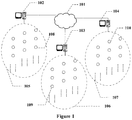
- Figure 1 is an exemplary topological graph of an intelligent wind farm cluster control system according to the present disclosure.
- a cloud server 101 is arranged in the cloud and is configured to receive and store various kinds of data (such as wind turbine parameter, environmental parameter and operating parameter) relevant to wind turbine and operation of wind turbine, which is collected from multiple wind farms 105, 106 and 107.
- a cloud server 101 may further coordinate and manage wind turbines in the multiple wind farms 105, 106 and 107 based on the received data relevant to wind turbine and operation of wind turbine.
- the multiple wind farms 105, 106 and 107 are provided with wind farm central monitoring systems 102, 103 and 104 respectively.
- Each of the wind turbines (such as wind turbines 108, 109 and 110) in the multiple wind farms 105, 106 and 107 uploads, its collected data (such as wind turbine parameter, environmental parameter and operating parameter) relevant to wind turbine and operation of wind turbine, to the wind farm central monitoring systems 102, 103 and 104 in its wind farm.
- the data uploaded by each of the wind turbines may include geographical location data (such as geographical location coordinates) thereof and wind condition data (such as a wind speed value and a wind direction value) detected in a real-time manner.
- the wind farm central monitoring systems 102, 103 and 104 receive, the data (including geographical location data of the wind turbine and wind condition data detected by the wind turbine in a real-time manner) relevant to wind turbine and operation of wind turbine, collected by each of the wind turbines in their respective wind farms 105, 106 and 107, and distribute data collected by each wind turbine to other wind turbines in their respective wind farms 105, 106 and 107.
- each wind turbine may perform corresponding control, such as yawing control and/or pitch control, on its operation device based on the geographical location data as received and the wind condition data detected in a real-time manner.
- the wind farm central monitoring systems 102, 103 and 104 communicate with the cloud server 101 respectively, to upload the various kinds ofdata (such as wind turbine parameter, environmental parameter and operating parameter) relevant to wind turbine and operation of wind turbine, collected by wind turbines in their respective wind farms.
- various kinds ofdata such as wind turbine parameter, environmental parameter and operating parameter
- Each of the wind turbines (such as the wind turbine 108) may be provided with various kinds of sensors at multiple locations to collect its geographical location data and operating parameter.
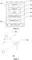
- Figure 2 is an exemplary schematic diagram of sensors arranged in a wind turbine according to the present disclosure.
- the wind turbine 108 is at least provided with an anemometer 202, an anemoscope 203 and a locator 204.
- the anemometer 202 and the anemoscope 203 are configured to detect a wind speed and a wind direction respectively.
- the locator 204 is configured to collect geographical location coordinates of the wind turbine 108.
- other sensors such as a pressure-altitude sensor 205 configured to detect an altitude of the wind turbine 108 and a temperature sensor 206 configured to measure temperatures of multiple parts of the wind turbine 108, may also be provided.
- a main control system 201 of the wind turbine 108 uploads the detected parameter data (including but not limited to a wind speed value, a wind direction value, geographical location coordinates, an altitude value, a temperature value and so on) to the wind farm central monitoring system 102.
- Each wind turbine generates virtual radar data as a reference for its autonomous operating control, based on the geographical location data of other wind turbines received from the wind farm central monitoring system in its wind farm and the wind condition data detected in a real-time manner.
- FIG. 3 is a schematic diagram of polar coordinates of a wind turbine in a wind farm and generated virtual radar according to the present disclosure.
- a wind turbine 301 establishes a polar coordinate system taking a location of itself (a current wind turbine) as a pole and a ray in a predetermined angle (for example, due north) from the pole as a polar axis.
- location data of other wind turbines for example, a wind turbine 302 in the same wind farm are each expressed as polar coordinates with a distance r from the pole and an angle a relative to the polar axis.
- the vertical direction (due north) shown in Figure 3 is considered as the polar axis, ie., a direction with an angle of 0 degree.
- the polar angle a of the wind turbine 302 is determined based on magnitude and sign of the calculated sine value sin a and the calculated cosine value cos a .
- the polar angle of the wind turbine 302 is determined as a .
- the polar angle of the wind turbine 302 is determined as a +90.
- the polar angle of the wind turbine 302 is determined as a +180.
- the polar angle of the wind turbine 302 is determined as a +270.
- the polar angle of the wind turbine 302 is determined as 90.
- the polar angle of the wind turbine 302 is determined as 180.
- the polar angle of the wind turbine 302 is determined as 270.
- the polar angle of the wind turbine 302 is a . If it is assumed that a variable for calculating the polar angle of the wind turbine 303 is ⁇ , then the polar angle of the wind turbine 303 is ⁇ +90. Similarly, polar coordinates data of other wind turbines in the same wind farm are calculated with the above method and are considered as their location data.
- virtual radar as shown in Figure 3 may be established. Based on the virtual radar, the wind turbine 301 can locate other wind turbines in the wind farm, such as the wind turbine 302 and the wind turbine 303.
- each wind turbine may store polar coordinates of wind turbines in the wind farm in association with the wind speed values and the wind direction values measured from the wind turbines.
- polar coordinate data of each wind turbine, and the wind speed value and the wind direction value measured from other wind turbines and received by the each wind turbine may be stored in a form of a multidimensional array.
- polar coordinate data of each wind turbine, and an altitude value, the wind speed value and the wind direction value measured from other wind turbines and received by the each wind turbine are stored in a multidimensional array in an associated manner.
- the angle value 1 to the angle value n are polar angle values of wind turbine 1 to wind turbine n respectively.
- the distance value 1 to the distance value n are polar distance values of the wind turbine 1 to the wind turbine n respectively.
- the wind speed value 1 to the wind speed value n are wind speed values measured from the wind turbine 1 to the wind turbine n respectively.
- the wind direction value 1 to the wind direction value n are wind direction values measured from the wind turbine 1 to the wind turbine n respectively.
- the altitude value 1 to the altitude value n are altitude values measured from the wind turbine 1 to the wind turbine n respectively.
- the current wind turbine may perform corresponding control, such as yawing control and/or pitch control, on its operation device, based on polar coordinate data of the wind turbine 1 to the wind turbine n and wind condition data measured in a real-time manner from the wind turbine 1 to the wind turbine n, which are stored in an associated manner.
- control such as yawing control and/or pitch control
- Figure 4 is a flow chart of an operation control method for a wind turbine according to the first embodiment of the present disclosure.
- the method according to the embodiment is implemented in a main control system of the wind turbine.
- step S410 data of a current orientation of a nacelle of a current wind turbine is acquired.
- the current orientation of the nacelle of the current wind turbine is usually consistent with a yawing angle of the current wind turbine. Therefore, optionally, in step S410, a yawing angle value read from a yawing counter of the current wind turbine is obtained, and the data of the current orientation of the nacelle of the current wind turbine is obtained from the yawing angle value.
- the method for acquiring the current orientation of the nacelle of the current wind turbine is not limited to the above manner, other devices such as a direction finder (such as a manual radio direction finer or an electronic compass direction finder) arranged on the nacelle may also be used to acquire the data of the current orientation.
- step S420 an operation device of the current wind turbine is controlled based on the data of the orientation, location data of each wind turbine in a wind farm, and wind condition data measured from the each wind turbine, to increase power generation amount of the current wind turbine.
- the main control system of the wind turbine may predict wind condition variation of the current wind turbine based on the orientation of the current wind turbine, and data relevant to locations of other wind turbines in the wind farm and wind condition data measured from each wind turbine in a real-time manner which are received from a wind farm central monitoring system.
- Control strategy adjustment is performed in advance on the operation device of the current wind turbine by utilizing existing hardware testing equipment, thus increasing power generation amount of the current wind turbine without adding additional hardware testing equipment, and saving operating cost.
- the operation control method for the wind turbine further includes: receiving geographical location coordinates (for example, GPS coordinates) measured from other wind turbines, and calculating polar coordinates of the other wind turbines based on geographical location coordinates of the current wind turbine and the geographical location coordinates measured from the other wind turbines.
- geographical location coordinates for example, GPS coordinates
- calculating polar coordinates of the other wind turbines based on geographical location coordinates of the current wind turbine and the geographical location coordinates measured from the other wind turbines.
- the operation control method for the wind turbine further includes: receiving wind speed values and wind direction values measured from the other wind turbines, and storing the polar coordinates of each wind turbine in the wind farm in association with the wind speed value and the wind direction value measured from the each wind turbine.
- Figure 5 is a flow chart of an operation control method for a wind turbine according to the second embodiment of the present disclosure. An exemplary processing of step S420 shown in Figure 4 is described in the second embodiment.
- step S510 a wind turbine whose location is consistent with the current orientation is selected as a forward-direction wind turbine.
- the wind condition data measured from the selected forward-direction wind turbine is taken as a reference for predicting wind condition variation to perform corresponding control strategy adjustment in advance.
- location data whose polar angle has a difference, within a predetermined angle range, with respect to the polar angle of the current orientation of the nacelle of the current wind turbine, is selected from the location data of other wind turbines in the wind farm, and a wind turbine corresponding to the selected location data is determined as the forward-direction wind turbine.
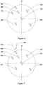
- FIG. 6 is an exemplary schematic diagram of selecting the forward-direction wind turbine according to the second embodiment of the present disclosure.
- locations of wind turbines 404 and 405 are basically consistent with a current orientation of a nacelle of the current wind turbine 401. That is, a difference between a polar angle of each of the wind turbines 404, 405 and a polar angle of the current orientation of the nacelle of the current wind turbine 401 is within a predetermined angle range (for example, [-2 degree, 2 degree]) respectively. Therefore, the wind turbine 404 or the wind turbine 405 can be considered as the current forward-direction wind turbine of the wind turbine 401.
- the number of the wind turbine whose location is consistent with the current orientation may be more than one. Any one of the more than one wind turbine can be selected as the current forward-direction. However, as a wind turbine close to the current wind turbine has a similar wind condition as the current wind turbine, it is more appropriate to determine wind condition data measured from such a wind turbine as a reference.
- the selecting the forward-direction wind turbine may further include: if the number of the wind turbine, corresponding to the location data whose polar angle has the difference, within the predetermined angle range, with respect to the polar angle of the current orientation of the nacelle of the current wind turbine, is more than one, selecting, from the more than one corresponding wind turbine, a wind turbine which has a minimum distance from the current wind turbine, as the forward-direction wind turbine.
- the wind condition of the wind turbine selected as the reference will differ greatly from the wind condition of the current wind turbine due to the difference in altitude. That is, the wind condition of the wind turbine selected as the reference has a low reference value.
- the operation control method for the wind turbine according to the embodiment of the present disclosure further includes: receiving altitude values measured from the other wind turbines, and storing the polar coordinates of each wind turbine in the wind farm in association with an altitude value, the wind speed value and the wind direction value measured from the each wind turbine.
- a wind turbine which satisfies the following condition is selected, from location data of the other wind turbines in the wind farm, as the forward-direction wind turbine: its polar angle has a difference, within a predetermined angle difference range, with respect to the polar angle of the current orientation of the nacelle of the current wind turbine, and its altitude value has a difference, within a predetermined altitude difference range (for example, [-20 meters, 20 meters]), with respect to the altitude value of the current wind turbine. If an altitude of a wind turbine differs greatly from the altitude of the current wind turbine (for example, there is an altitude difference greater than 100 meters), then there is no actual reference value to select such a wind turbine as the forward-direction wind turbine.
- the wind turbine whose location is consistent with the current orientation of the nacelle of the current wind turbine and whose altitude is close to the altitude of the current wind turbine, is selected as the current forward-direction wind turbine for the current wind turbine, to perform control strategy adjustment for the current wind turbine based on relatively reliable wind condition data.
- step S520 the operation device of the wind turbine is controlled based on the location data of the forward-direction wind turbine, the wind speed value and/or the wind direction value measured from the forward-direction wind turbine and an operation state of the current wind turbine, to increase power generation amount of the current wind turbine.
- yawing control is performed on the current wind turbine in advance based on the wind speed value and the wind direction value measured from the forward-direction wind turbine and a distance between the forward-direction wind turbine and the current wind turbine.
- FIG 7 is an exemplary schematic diagram of processing of step S520. Referring to Figure 7 , it is assumed that a wind direction 501 is consistent with a current orientation (i.e., a current yawing angle) of a nacelle of a wind turbine 401 before wind direction variation is detected, and a current forward-direction wind turbine for the wind turbine 401 is a wind turbine 405.
- a current orientation i.e., a current yawing angle
- a control time for pre-yaw is calculated based on a distance between the wind turbine 401 and the wind turbine 405, a variation value between wind direction angles, and a wind speed value measured from the wind turbine 405, to control a yawing system of the wind turbine 401 to perform yawing towards the wind direction 502 in advance, for realizing accurate and autonomous yawing to increase power generation amount.
- existing hardware testing equipment is utilized to perform accurate yawing control in advance without adding additional testing equipment, which saves operating cost.
- the wind direction value measured by the wind turbine 401 is taken as a yawing reference, which is similar to the existing yawing control.
- Figure 8 is a flow chart of an operation control method for a wind turbine according to a third embodiment of the present disclosure. An exemplary processing of step S520 shown in Figure 5 is described in the third embodiment.
- the processing according to the third embodiment is particularly suitable for a situation in which a wind direction suddenly changes and/or frequently changes.
- step S810 a wind turbine, which has a maximum variation of the wind direction value, is selected, from the other wind turbines, as a current first predetermined forward-direction wind turbine.
- the current first predetermined forward-direction wind turbine selected herein may be understood as a wind turbine for determining a target direction to which the current wind turbine is to yaw in a case that a condition for subsequently performing yawing is met.
- the current wind turbine performs yawing towards a wind direction detected by the determined first predetermined forward-direction wind turbine.
- step S820 whether yawing control needs to be performed is determined based on changing states of the wind conditions of the forward-direction wind turbine and the first predetermined forward-direction wind turbine.
- wind speed values measured from the forward-direction wind turbine and the first predetermined forward-direction wind turbine are both greater than a predetermined first wind speed threshold, and variation values of wind directions measured from the forward-direction wind turbine and the first predetermined forward-direction wind turbine are both greater than a predetermined threshold of wind direction variation, then it is determined that yawing control needs to be performed.
- yawing control is performed only in a case that the wind speed measured from the first predetermined forward-direction wind turbine is high and the variation value of the wind direction measured from the first predetermined forward-direction wind turbine is great.
- any one of the wind speed values measured from the forward-direction wind turbine and the first predetermined forward-direction wind turbine is not greater than the first wind speed threshold, or any one of the variation values of the wind directions measured from the forward-direction wind turbine and the first predetermined forward-direction wind turbine is not greater than a first wind direction threshold, then it is determined that yawing control does not need to be performed.
- step S820 If in step S820, it is determined that yawing control needs to be performed, then in step S830, yawing control is performed on the current wind turbine in advance based on the wind speed value and the wind direction value measured from the first predetermined forward-direction wind turbine, to make the current wind turbine yaw to the wind direction detected by the first predetermined forward-direction wind turbine, thereby increasing power generation amount of the current wind turbine.
- the current wind turbine is controlled to enter into a standby state, and a yawing system of the wind turbine is controlled to perform yawing based on the wind direction value measured from the first predetermined forward-direction wind turbine.
- a delay in starting time caused by yawing is reduced, and a running state of power generating is immediately entered, thus increasing power generation amount of the current wind turbine.
- yawing control is performed on the current wind turbine in advance based on the distance between the first predetermined forward-direction wind turbine and the current wind turbine, and the wind speed value and the wind direction value measured from the first predetermined forward-direction wind turbine. That is, the wind speed value and the wind direction value measured from the current first predetermined forward-direction wind turbine are considered as references for performing autonomous yawing control, to make the current wind turbine yaw to the wind direction detected by the first predetermined forward-direction wind turbine, thereby increasing power generation amount of the current wind turbine.
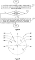
- Figure 9 shows an example of processing of the operation control method for the wind turbine according to the third embodiment of the present disclosure.
- the currently known wind direction is a wind direction 501
- a wind turbine 401 determines that a wind turbine 403 has a maximum variation of wind direction based on received wind condition data measured in a real-time manner from each wind turbine.
- the wind turbine 403 is selected as the first predetermined forward-direction wind turbine, and yawing is to be performed towards a wind direction 601 measured by the wind turbine 403.
- a control time for pre-yaw is calculated based on a distance between the wind turbine 401 and the wind turbine 403, a variation value of a wind direction angle and a wind speed value measured from the wind turbine 403, for controlling a yawing system of the wind turbine 401 to yaw towards the wind direction 601 in advance, to achieve autonomous yawing accurately and increase power generation amount.
- step S820 If in step S820, it is determined that yawing control does not need to be performed, then control may be performed based on a usual control strategy, which is no described herein.
- FIG 10 is a flow chart of an operation control method for a wind turbine according to the fourth embodiment of the present disclosure. Another illustrative processing of step S520 shown in Figure 5 is described in the fourth embodiment.
- the processing according to the fourth embodiment is particularly suitable for a situation in which a wind speed suddenly changes and/or frequently changes.
- step S1010 a wind turbine, which has a maximum variation of the wind speed value, is selected, from the other wind turbines, as a current second predetermined forward-direction wind turbine.
- the wind condition data measured from the second predetermined forward-direction wind turbine is taken as a reference for performing corresponding control on the current wind turbine in subsequent processing.
- step S1020 whether control needs to be performed is determined based on changing states of wind speeds of the forward-direction wind turbine and the first predetermined forward-direction wind turbine.
- a variation value of the wind speed measured from the second predetermined forward-direction wind turbine is greater than a predetermined first wind speed variation threshold, and a variation value of the wind speed measured from the forward-direction wind turbine is greater than a predetermined second wind speed variation threshold, then it is determined that control needs to be performed.
- the second wind speed variation threshold maybe less than the first wind speed variation threshold here. That is, only in a case that the variation values of the wind speeds measured from the forward-direction wind turbine and the second predetermined forward-direction wind turbine are both great, it is determined that control needs to be performed.
- the variation value of the wind speed measured from the second predetermined forward-direction wind turbine is not greater than the first wind speed variation threshold, or the variation value the wind speed measured from the forward-direction wind turbine is not greater than the second wind speed variation threshold, then it is determined that control does not need to be performed.
- step S1030 control is performed on the current wind turbine based on the wind condition data measured from the second predetermined forward-direction wind turbine.
- over-speed protection control or control strategy optimizing adjustment may be performed on the current wind turbine based on magnitude of the wind speed value measured from the second predetermined forward-direction wind turbine.
- yawing control and pitch control are performed on the current wind turbine in advance based on a distance between the second predetermined forward-direction wind turbine and the current wind turbine, the wind speed value and the wind direction value measured from the second predetermined forward-direction wind turbine. That is, if the wind speed value measured from the second predetermined forward-direction wind turbine is in a safety range of operation of a wind turbine, timely and advanced yawing control and pitch control may be performed with utilization of an increase in the wind speed, to increase power generation amount of the current wind turbine. Processing of the yawing control mentioned herein is similar to that in the second embodiment, which is not described herein.
- an expected arrival time of a gale is acquired based on the location data of the second predetermined forward-direction wind turbine and the wind speed value measured from the second predetermined forward-direction wind turbine, to make preparations for performing over-speed protection control on the current wind turbine.
- over-speed protection control is performed in advance in a case that a wind speed suddenly increases to exceed the cut-out wind speed of wind turbine, thereby ensuring operation life of the wind turbine.
- FIG 11 is an exemplary schematic diagram of processing of step S1030.
- the topological graph of the wind farm shown in the Figure 5 is still taken as an example. Reference is made to Figure 11 , and it is assumed that a wind direction changes frequently or changes suddenly, and a wind turbine 401 determines that a wind turbine 405 has a maximum variation of wind speed, which changes from a wind speed 801 to a wind speed 802, based on the received wind condition data measured in a real-time manner from each wind turbine. In this case, the wind turbine 405 is selected as the second predetermined forward-direction wind turbine.
- a distance between the wind turbine 405 and the wind turbine 401 is obtained based on the location data of the wind turbine 405, and an expected arrival time of a gale is acquired based on the wind speed value measured from wind turbine 405 and data of the distance.
- the wind turbine 401 makes preparations for performing over-speed protection on itself to ensure its safe operation, which facilitates extending its operation life.
- FIG 12 is a schematic diagram of another exemplary processing of step S1030.
- the topological graph of the wind farm shown in the Figure 5 is still taken as an example.
- Reference is made to Figure 12 and it is assumed that a wind turbine 401 is in a stopped state, and the wind turbine 401 determines that a wind turbine 405 has a maximum variation of wind speed, which changes to a wind speed 602, based on the received wind condition data measured in a real-time manner from each wind turbine. In this case, the wind turbine 405 is selected as the second predetermined forward-direction wind turbine.
- step S410 is performed to achieve automatic yawing or achieve wind alignment in advance, and performing of the operation control method for the wind turbine according to the present disclosure is continued.
- Figure 13 is a logic block diagram of an operation control apparatus for a wind turbine according to the fifth embodiment of the present disclosure.
- the operation control apparatus may be provided in a main control system of the wind turbine, to perform the operation control method for the wind turbine according to the first embodiment.
- the operation control apparatus for the wind turbine includes an orientation determining unit 1310 and an operation control unit 1320.
- the orientation determining unit 1310 is configured to acquire data of a current orientation of a nacelle of a current wind turbine.
- the operation control unit 1320 is configured to control an operation device of the current wind turbine based on the data of the orientation, location data of each wind turbine in a wind farm, and wind condition data measured from the each wind turbine, to increase power generation amount of the current wind turbine.
- the location data of each wind turbine in the wind farm is data of polar coordinates, with the current wind turbine as a pole and a ray in a predetermined angle from the pole as a polar axis.
- the operation control apparatus for the wind turbine further includes:
- the parameter receiving unit 1330 is further configured to receive geographical location coordinates measured from other wind turbines.
- the operation control apparatus for the wind turbine further includes: a polar coordinate calculation unit 1340, configured to calculate polar coordinates of other wind turbines based on a geographical location coordinate of the current wind turbine and the geographical location coordinates measured from the other wind turbines.
- the orientation determining unit 1310 is configured to acquire a yawing angle value read from a yawing counter of the current wind turbine, and acquire the data of the current orientation of the nacelle of the current wind turbine from the yawing angle value.
- Figure 14 is a logic block diagram of an operation control apparatus for a wind turbine according to the sixth embodiment of the present disclosure.
- the operation control apparatus for the wind turbine is a specific implementation of the operation control apparatus shown in the fifth embodiment.
- the operation control unit 1320 in the operation control apparatus for the wind turbine further includes: a forward-direction wind turbine selecting unit 1420, configured to select a wind turbine whose location is consistent with the current orientation as a current forward-direction wind turbine.
- the operation control unit 1320 is configured to control the operation device of the wind turbine based on the location data of the forward-direction wind turbine, the wind speed value and/or the wind direction value measured from the forward-direction wind turbine and an operation state of the current wind turbine, to increase power generation amount of the current wind turbine.
- the forward-direction wind turbine selecting unit 1420 is configured to select, from the location data of other wind turbines in the wind farm, location data whose polar angle has a difference, within a predetermined angle range, with respect to a polar angle of the current orientation of the nacelle of the current wind turbine, and determine a wind turbine corresponding to the selected location data as the forward-direction wind turbine.
- the forward-direction wind turbine selecting unit 1420 is further configured to: if the number of the wind turbine, corresponding to the location data whose polar angle has the difference, within the predetermined angle range, with respect to the polar angle of the current orientation of the nacelle of the current wind turbine, is more than one, select, from the more than one corresponding wind turbine, a wind turbine which has a minimum distance from the current wind turbine, as the forward-direction wind turbine.
- the parameter receiving unit 1330 is further configured to receive altitude values measured from the other wind turbines.
- the parameter storage unit 1340 is configured to store the polar coordinates of each wind turbine in the wind farm in association with an altitude value, the wind speed value and the wind direction value measured from the each wind turbine.
- the forward-direction wind turbine selecting unit 1420 is configured to select, from the location data of the other wind turbines in the wind farm, a wind turbine which satisfies the following condition as the forward-direction wind turbine: its polar angle has a difference, within a predetermined angle difference range, with respect to the polar angle of the current orientation of the nacelle of the current wind turbine, and its altitude value has a difference, within a predetermined altitude difference range, with respect to the altitude value of the current wind turbine.
- the operation control unit 1320 is configured to: perform yawing control on the current wind turbine in advance based on the wind speed value and the wind direction value measured from the forward-direction wind turbine and a distance between the forward-direction wind turbine and the current wind turbine, if the current wind turbine is in a running state, and a wind direction difference between the wind direction value measured from the forward-direction wind turbine and a wind direction value previously measured from the forward-direction wind turbine is beyond a predetermined wind direction difference range.
- Figure 15 is a logic block diagram of an operation control apparatus for a wind turbine according to a seventh embodiment of the present disclosure.
- the operation control apparatus for the wind turbine is a specific implementation of the operation control unit 1320 in the operation control apparatus shown in the sixth embodiment.
- the operation control unit 1320 includes a first predetermined forward-direction wind turbine selecting unit 1510, a first control determining unit 1520 and a first control performing unit 1530.
- the first predetermined forward-direction wind turbine selecting unit 1510 is configured to select, from the other wind turbines, a wind turbine, which has a maximum variation of the measured wind direction value, as a current first predetermined forward-direction wind turbine.
- the first control determining unit 1520 is configured to determine, based on changing states of wind conditions of the forward-direction wind turbine and the first predetermined forward-direction wind turbine, whether yawing control needs to be performed.
- the first control determining unit 1520 is configured to:
- the first control performing unit 1530 is configured to: perform yawing control on the current wind turbine in advance based on the wind speed value and the wind direction value measured from the first predetermined forward-direction wind turbine, if the first control determining unit 1520 determines that yawing control needs to be performed, to make the current wind turbine yaw to a wind direction detected by the first predetermined forward-direction wind turbine.
- the first control performing unit 1530 is configured to:
- Figure 16 is a logic block diagram of an operation control apparatus for a wind turbine according to the eighth embodiment of the present disclosure.
- the operation control apparatus for the wind turbine is another specific implementation of the operation control unit 1320 in the operation control apparatus shown in the sixth embodiment.
- the operation control unit 1320 includes a second predetermined forward-direction wind turbine selecting unit 1610, a second control determining unit 1620 and a second control performing unit 1630.
- the second predetermined forward-direction wind turbine selecting unit 1610 is configured to select, from the other wind turbines, a wind turbine which has a maximum variation of the measured wind speed value, as a current second predetermined forward-direction wind turbine.
- the second control determining unit 1620 is configured to determine, based on changing states of wind speeds of the forward-direction wind turbine and the first predetermined forward-direction wind turbine, whether yawing control needs to be performed.
- the second control determining unit 1620 is configured to:
- the second control performing unit 1630 is configured to: control the current wind turbine based on the wind condition data measured from the second predetermined forward-direction wind turbine, if the second control determining unit 1620 determines that control needs to be performed.
- the second control performing unit 1630 is configured to:
- the second control performing unit 1630 is configured to: control the current wind turbine enter into a standby state, and perform yawing based on the distance between the second predetermined forward-direction wind turbine and the current wind turbine and the wind condition data measured from the second predetermined forward-direction wind turbine, if the current wind turbine is in a stopped state.
- a wind turbine including the above operation control apparatus is further provided according to an embodiment of the present disclosure.
- each component/step described in the present disclosure may be divided into more components/steps, and two or multiple components/steps or parts of component/step may be combined to form a new component/step to achieve the object of the present disclosure.
- the method according to the present disclosure may be implemented with hardware or firmware, or may be implemented with software or computer code that may be stored in record medium (such like CD ROM, RAM, floppy disk, hard disk or magneto-optical disk). Or, the method may be implemented with computer code originally stored in remote record medium or non-transient computer-readable medium, which can be downloaded via network and will be stored in local record medium. Hence, the method described herein may be processed by software stored in record medium applied to a general-purpose computer, a specific processor or programmable or special hardware (such as ASIC or FPGA).
- record medium such like CD ROM, RAM, floppy disk, hard disk or magneto-optical disk.
- the method may be implemented with computer code originally stored in remote record medium or non-transient computer-readable medium, which can be downloaded via network and will be stored in local record medium.
- the method described herein may be processed by software stored in record medium applied to a general-purpose computer, a specific processor or programmable or special hardware (such as ASIC or FPGA
- a computer, a processor, a microprocessor controller or programmable hardware includes a memory module (such as RAM, ROM, flash memory) that can store or receive software or computer code, and the method described herein is implemented when the software or computer code is accessed and executed by a computer, a processor or hardware.
- a general-purpose computer accesses code for implementing the processing described herein, the general-purpose computer is switched to a special-purpose computer for executing the processing described herein as a result of executing the code.
Landscapes
- Engineering & Computer Science (AREA)
- Life Sciences & Earth Sciences (AREA)
- Sustainable Development (AREA)
- Sustainable Energy (AREA)
- Chemical & Material Sciences (AREA)
- Combustion & Propulsion (AREA)
- Mechanical Engineering (AREA)
- General Engineering & Computer Science (AREA)
- Wind Motors (AREA)
Applications Claiming Priority (2)
| Application Number | Priority Date | Filing Date | Title |
|---|---|---|---|
| CN201610248976.XA CN107304746B (zh) | 2016-04-20 | 2016-04-20 | 风力发电机组及其运行控制方法与设备 |
| PCT/CN2017/077316 WO2017181798A1 (fr) | 2016-04-20 | 2017-03-20 | Turbine éolienne et procédé et dispositif de commande de fonctionnement pour cette dernière |
Publications (3)
| Publication Number | Publication Date |
|---|---|
| EP3296563A1 true EP3296563A1 (fr) | 2018-03-21 |
| EP3296563A4 EP3296563A4 (fr) | 2019-01-09 |
| EP3296563B1 EP3296563B1 (fr) | 2021-05-05 |
Family
ID=60116582
Family Applications (1)
| Application Number | Title | Priority Date | Filing Date |
|---|---|---|---|
| EP17785283.7A Active EP3296563B1 (fr) | 2016-04-20 | 2017-03-20 | Turbine éolienne et procédé et dispositif de commande de fonctionnement pour cette dernière |
Country Status (7)
| Country | Link |
|---|---|
| US (1) | US10267292B2 (fr) |
| EP (1) | EP3296563B1 (fr) |
| KR (1) | KR102056531B1 (fr) |
| CN (1) | CN107304746B (fr) |
| AU (1) | AU2017254511B2 (fr) |
| ES (1) | ES2873748T3 (fr) |
| WO (1) | WO2017181798A1 (fr) |
Cited By (1)
| Publication number | Priority date | Publication date | Assignee | Title |
|---|---|---|---|---|
| CN112879220A (zh) * | 2021-03-16 | 2021-06-01 | 上海电气风电集团股份有限公司 | 风机控制方法、系统和可读存储介质 |
Families Citing this family (15)
| Publication number | Priority date | Publication date | Assignee | Title |
|---|---|---|---|---|
| DE102015114958A1 (de) * | 2015-09-07 | 2017-03-09 | Wobben Properties Gmbh | Verfahren zum Betreiben eines Windparks |
| CN107327375B (zh) * | 2016-04-28 | 2019-08-02 | 北京天诚同创电气有限公司 | 风机叶片参数确定方法及装置 |
| WO2018005363A1 (fr) * | 2016-07-01 | 2018-01-04 | Cfph, Llc | Interface pour des options d'emplacement de glissement de terrain |
| CN110206682B (zh) | 2018-02-28 | 2020-06-26 | 北京金风科创风电设备有限公司 | 动态确定偏航控制精度的方法和装置 |
| CN110273813B (zh) * | 2018-03-16 | 2021-02-02 | 北京金风慧能技术有限公司 | 风力发电机组对风偏航的控制方法、装置及设备 |
| CN109026530B (zh) * | 2018-07-20 | 2019-10-11 | 国网冀北电力有限公司迁西县供电分公司 | 一种风力发电机组智能学习方法 |
| CN109253048B (zh) * | 2018-08-31 | 2020-06-05 | 北京金风科创风电设备有限公司 | 风力发电机组的运行控制方法、装置、设备及存储介质 |
| KR102143757B1 (ko) * | 2019-05-07 | 2020-08-12 | 오토시맨틱스 주식회사 | 딥러닝을 포함한 인공지능을 적용시킨 풍력 발전장치 |
| CN113931806B (zh) * | 2020-06-29 | 2023-09-22 | 金风科技股份有限公司 | 风力发电机组及其控制方法、控制器和控制系统 |
| KR102382310B1 (ko) * | 2020-11-17 | 2022-04-04 | 한국수력원자력 주식회사 | 부유식 라이더의 가용율을 향상시키기 위한 드론 운용 시스템 및 방법 |
| US12297811B2 (en) * | 2021-06-24 | 2025-05-13 | Board Of Regents, The University Of Texas System | System and method to maximize power production by wind turbines |
| US11639710B2 (en) | 2021-06-25 | 2023-05-02 | WindESCo, Inc. | Systems and methods of coordinated yaw control of multiple wind turbines |
| CN113586335B (zh) * | 2021-09-16 | 2022-07-19 | 中国华能集团清洁能源技术研究院有限公司 | 用于大湍流工况的风力发电机防超速组控制方法及系统 |
| CN117145701A (zh) * | 2023-09-19 | 2023-12-01 | 广西民海能源有限公司 | 一种风力发电机组的偏航控制方法及系统 |
| CN118327881A (zh) * | 2024-04-11 | 2024-07-12 | 大唐可再生能源试验研究院有限公司 | 基于风向风速湍流动能的大型风力机偏航联合控制方法 |
Family Cites Families (41)
| Publication number | Priority date | Publication date | Assignee | Title |
|---|---|---|---|---|
| DE10051513A1 (de) * | 2000-10-17 | 2002-04-25 | Aloys Wobben | Windpark |
| DE10137272A1 (de) * | 2001-07-31 | 2003-02-27 | Aloys Wobben | Frühwarnsystem für Windenergieanlagen |
| NL1021078C1 (nl) * | 2002-07-15 | 2004-01-16 | Energieonderzoek Ct Petten Ecn | Werkwijze en inrichting betreffende stromingsenergie zoals een windturbinepark. |
| JP3774689B2 (ja) * | 2002-09-06 | 2006-05-17 | 三菱電機株式会社 | 風力発電用風車建設予定地の風向風速計測方法 |
| DE10320087B4 (de) | 2003-05-05 | 2005-04-28 | Aloys Wobben | Verfahren zum Betreiben eines Windparks |
| NL1023666C2 (nl) * | 2003-06-14 | 2004-12-20 | Energieonderzoek Ct Petten Ecn | Werkwijze of inrichting om energie aan een stromend fluïdum te onttrekken. |
| US7040859B2 (en) * | 2004-02-03 | 2006-05-09 | Vic Kane | Wind turbine |
| US8649911B2 (en) * | 2005-06-03 | 2014-02-11 | General Electric Company | System and method for operating a wind farm under high wind speed conditions |
| US20070124025A1 (en) | 2005-11-29 | 2007-05-31 | General Electric Company | Windpark turbine control system and method for wind condition estimation and performance optimization |
| CN101684774B (zh) * | 2008-09-28 | 2012-12-26 | 通用电气公司 | 一种风力发电系统及风力发电机的测风方法 |
| JP4698718B2 (ja) | 2008-09-30 | 2011-06-08 | 株式会社日立製作所 | 風力発電装置群の制御装置及び制御方法 |
| CN101476541B (zh) * | 2008-12-26 | 2011-02-16 | 华锐风电科技(集团)股份有限公司 | 用于风力发电机组的独立变桨控制系统及控制方法 |
| US7941304B2 (en) * | 2009-04-30 | 2011-05-10 | General Electric Company | Method for enhancement of a wind plant layout with multiple wind turbines |
| GB2481461A (en) * | 2010-06-21 | 2011-12-28 | Vestas Wind Sys As | Control of a downstream wind turbine in a wind park by sensing the wake turbulence of an upstream turbine |
| US8035241B2 (en) * | 2010-07-09 | 2011-10-11 | General Electric Company | Wind turbine, control system, and method for optimizing wind turbine power production |
| US8202049B2 (en) * | 2010-08-31 | 2012-06-19 | Catch the Wind, Inc. | Independent blade pitch control |
| US20110193344A1 (en) * | 2010-12-29 | 2011-08-11 | Vestas Wind Systems A/S | Control Network for Wind Turbine Park |
| US8489247B1 (en) * | 2011-03-18 | 2013-07-16 | Rockwell Collins, Inc. | Agent-based chaotic control of wind turbines |
| GB201109897D0 (en) * | 2011-06-13 | 2011-07-27 | Romax Technology Ltd | A method for managing wind farms |
| US9644610B2 (en) * | 2011-12-06 | 2017-05-09 | Vestas Wind Systems A/S | Warning a wind turbine generator in a wind park of an extreme wind event |
| US20120133138A1 (en) * | 2011-12-22 | 2012-05-31 | Vestas Wind Systems A/S | Plant power optimization |
| EP2631470A1 (fr) * | 2012-02-23 | 2013-08-28 | Siemens Aktiengesellschaft | Procédé pour aligner l'angle de lacet d'une nacelle d'éolienne |
| DE102012013896A1 (de) * | 2012-07-13 | 2014-01-16 | E.N.O. Energy Systems Gmbh | Windenergieanlage |
| US9617975B2 (en) * | 2012-08-06 | 2017-04-11 | General Electric Company | Wind turbine yaw control |
| KR101418413B1 (ko) * | 2012-09-27 | 2014-07-09 | 삼성중공업 주식회사 | 풍력 발전 단지 제어 방법 |
| DE102012218484A1 (de) * | 2012-10-10 | 2014-04-10 | Wobben Properties Gmbh | Verfahren zum Betreiben einer Windenergieanlage |
| CN102945318B (zh) * | 2012-10-29 | 2015-10-28 | 上海电力学院 | 一种基于级联风机的超短期风速动态预测方法 |
| US8987929B2 (en) * | 2012-11-01 | 2015-03-24 | General Electric Company | System and method for operating wind farm |
| EP2757255A1 (fr) * | 2013-01-21 | 2014-07-23 | Alstom Wind, S.L.U. | Procédé de fonctionnement d'un parc éolien |
| US10151301B2 (en) | 2013-01-25 | 2018-12-11 | Vestas Wind Systems A/S | Control of wind turbines |
| WO2014125592A1 (fr) | 2013-02-14 | 2014-08-21 | 三菱重工業株式会社 | Ferme éolienne, son procédé d'exploitation et dispositif de commande |
| KR101407460B1 (ko) * | 2013-04-03 | 2014-06-13 | 삼성중공업 주식회사 | 풍력발전기 및 그 운영 방법 |
| US10044221B2 (en) * | 2013-12-16 | 2018-08-07 | Vestas Wind Systems A/S | Wind turbine generators with power backup system |
| EP2940295B1 (fr) * | 2014-04-29 | 2018-04-11 | General Electric Company | Système et procédé de commande d'un parc éolien |
| EP3309389B1 (fr) * | 2014-09-29 | 2019-08-14 | Vestas Wind Systems A/S | Vérification de capteur de position de lacet de nacelle d'éolienne |
| EP3037657A1 (fr) * | 2014-12-23 | 2016-06-29 | ABB Technology AG | Fonctionnement optimal de parc éolien |
| US20160215759A1 (en) * | 2015-01-28 | 2016-07-28 | Alliance For Sustainable Energy, Llc | Methods and systems for wind plant power optimization |
| EP3096004A1 (fr) * | 2015-05-18 | 2016-11-23 | ABB Technology AG | Réponse inertielle de parc éolien |
| CN104989592B (zh) * | 2015-07-07 | 2018-05-04 | 中能电力科技开发有限公司 | 风力发电机组机舱风向校正方法 |
| CN104963811B (zh) * | 2015-07-15 | 2018-03-06 | 上海电机学院 | 自适应风速的多级风力发电机及其控制方法 |
| EP3121442B2 (fr) * | 2015-07-20 | 2023-07-05 | GE Renewable Technologies Wind B.V. | Fonctionnement de turbines éoliennes |
-
2016
- 2016-04-20 CN CN201610248976.XA patent/CN107304746B/zh active Active
-
2017
- 2017-03-20 ES ES17785283T patent/ES2873748T3/es active Active
- 2017-03-20 EP EP17785283.7A patent/EP3296563B1/fr active Active
- 2017-03-20 WO PCT/CN2017/077316 patent/WO2017181798A1/fr not_active Ceased
- 2017-03-20 US US15/580,126 patent/US10267292B2/en active Active
- 2017-03-20 KR KR1020177037649A patent/KR102056531B1/ko active Active
- 2017-03-20 AU AU2017254511A patent/AU2017254511B2/en active Active
Cited By (2)
| Publication number | Priority date | Publication date | Assignee | Title |
|---|---|---|---|---|
| CN112879220A (zh) * | 2021-03-16 | 2021-06-01 | 上海电气风电集团股份有限公司 | 风机控制方法、系统和可读存储介质 |
| CN112879220B (zh) * | 2021-03-16 | 2022-11-01 | 上海电气风电集团股份有限公司 | 风机控制方法、系统和可读存储介质 |
Also Published As
| Publication number | Publication date |
|---|---|
| KR20180012826A (ko) | 2018-02-06 |
| ES2873748T3 (es) | 2021-11-03 |
| AU2017254511A1 (en) | 2017-12-14 |
| KR102056531B1 (ko) | 2019-12-16 |
| EP3296563A4 (fr) | 2019-01-09 |
| EP3296563B1 (fr) | 2021-05-05 |
| WO2017181798A1 (fr) | 2017-10-26 |
| US20180298880A1 (en) | 2018-10-18 |
| CN107304746A (zh) | 2017-10-31 |
| CN107304746B (zh) | 2020-07-17 |
| AU2017254511B2 (en) | 2019-03-07 |
| US10267292B2 (en) | 2019-04-23 |
Similar Documents
| Publication | Publication Date | Title |
|---|---|---|
| EP3296563B1 (fr) | Turbine éolienne et procédé et dispositif de commande de fonctionnement pour cette dernière | |
| US11578696B2 (en) | Method for determining the available power of a wind park, and corresponding wind park | |
| EP3645866B1 (fr) | Procédé mis en oeuvre par ordinateur pour ré-étalonner au moins un angle de lacet d'une éolienne, système respectif, procédé mis en oeuvre par ordinateur pour l'optimisation de parc éolien et parc éolien respectif | |
| US9995276B2 (en) | Control of wind turbines in response to wind shear | |
| AU2015374696B2 (en) | Method, device and system for compensating output power of wind turbine generator set | |
| US12123399B2 (en) | Load control method and apparatus for wind turbine generator system | |
| CN108317040B (zh) | 偏航对风矫正的方法、装置、介质、设备和风力发电机组 | |
| CN108798997B (zh) | 风力发电机组的控制方法、装置、控制器及系统 | |
| ES2951274T3 (es) | Sistema de control y procedimiento para el funcionamiento de una pluralidad de turbinas eólicas | |
| CN107514336B (zh) | 风速信息处理方法及装置和变桨控制方法、装置及系统 | |
| CN108167119B (zh) | 风力发电机组的主动偏航控制方法及控制器 | |
| CN110765640B (zh) | 一种转子有效风速的计算方法、系统及设备 | |
| CN107664096B (zh) | 偏航对风控制方法、装置及系统 | |
| CN107781117A (zh) | 风机方位距离的检测方法、装置及风力发电机组 | |
| EP3364020B1 (fr) | Procédé de commande, dispositif de commande maître, système et dispositif de commande central pour éoliennes | |
| CN119593970A (zh) | 基于rtk技术的叶片净空值与不平衡实时监测方法及装置 | |
| CN117803521B (zh) | 一种风机叶片防覆冰方法、系统、电子设备及存储介质 | |
| US12135014B2 (en) | Method and device for determining a rotor orientation of a rotor of a wind turbine | |
| CN107654335A (zh) | 风力发电机组的偏航控制方法及装置 | |
| CN120231692A (zh) | 风力发电机组的变桨控制方法及风力发电机组 | |
| CN121454546A (zh) | 雷达合成风速解算方法、装置、设备及存储介质 | |
| CN119401414A (zh) | 风电场发电功率的预测方法、装置、电子设备及存储介质 | |
| Korzhavin et al. | Universal computer vision system for monitoring the main parameters of wind turbines |
Legal Events
| Date | Code | Title | Description |
|---|---|---|---|
| STAA | Information on the status of an ep patent application or granted ep patent |
Free format text: STATUS: THE INTERNATIONAL PUBLICATION HAS BEEN MADE |
|
| PUAI | Public reference made under article 153(3) epc to a published international application that has entered the european phase |
Free format text: ORIGINAL CODE: 0009012 |
|
| STAA | Information on the status of an ep patent application or granted ep patent |
Free format text: STATUS: REQUEST FOR EXAMINATION WAS MADE |
|
| 17P | Request for examination filed |
Effective date: 20171211 |
|
| AK | Designated contracting states |
Kind code of ref document: A1 Designated state(s): AL AT BE BG CH CY CZ DE DK EE ES FI FR GB GR HR HU IE IS IT LI LT LU LV MC MK MT NL NO PL PT RO RS SE SI SK SM TR |
|
| AX | Request for extension of the european patent |
Extension state: BA ME |
|
| A4 | Supplementary search report drawn up and despatched |
Effective date: 20181210 |
|
| RIC1 | Information provided on ipc code assigned before grant |
Ipc: F03D 7/02 20060101AFI20181204BHEP |
|
| DAV | Request for validation of the european patent (deleted) | ||
| DAX | Request for extension of the european patent (deleted) | ||
| GRAP | Despatch of communication of intention to grant a patent |
Free format text: ORIGINAL CODE: EPIDOSNIGR1 |
|
| STAA | Information on the status of an ep patent application or granted ep patent |
Free format text: STATUS: GRANT OF PATENT IS INTENDED |
|
| INTG | Intention to grant announced |
Effective date: 20210120 |
|
| GRAS | Grant fee paid |
Free format text: ORIGINAL CODE: EPIDOSNIGR3 |
|
| GRAA | (expected) grant |
Free format text: ORIGINAL CODE: 0009210 |
|
| STAA | Information on the status of an ep patent application or granted ep patent |
Free format text: STATUS: THE PATENT HAS BEEN GRANTED |
|
| AK | Designated contracting states |
Kind code of ref document: B1 Designated state(s): AL AT BE BG CH CY CZ DE DK EE ES FI FR GB GR HR HU IE IS IT LI LT LU LV MC MK MT NL NO PL PT RO RS SE SI SK SM TR |
|
| RAP3 | Party data changed (applicant data changed or rights of an application transferred) |
Owner name: BEIJING ETECHWIN ELECTRIC CO., LTD. |
|
| REG | Reference to a national code |
Ref country code: GB Ref legal event code: FG4D |
|
| REG | Reference to a national code |
Ref country code: CH Ref legal event code: EP |
|
| REG | Reference to a national code |
Ref country code: AT Ref legal event code: REF Ref document number: 1390115 Country of ref document: AT Kind code of ref document: T Effective date: 20210515 |
|
| REG | Reference to a national code |
Ref country code: IE Ref legal event code: FG4D |
|
| REG | Reference to a national code |
Ref country code: DE Ref legal event code: R096 Ref document number: 602017038218 Country of ref document: DE |
|
| REG | Reference to a national code |
Ref country code: LT Ref legal event code: MG9D |
|
| REG | Reference to a national code |
Ref country code: GR Ref legal event code: EP Ref document number: 20210401949 Country of ref document: GR Effective date: 20210813 |
|
| REG | Reference to a national code |
Ref country code: AT Ref legal event code: MK05 Ref document number: 1390115 Country of ref document: AT Kind code of ref document: T Effective date: 20210505 |
|
| PG25 | Lapsed in a contracting state [announced via postgrant information from national office to epo] |
Ref country code: LT Free format text: LAPSE BECAUSE OF FAILURE TO SUBMIT A TRANSLATION OF THE DESCRIPTION OR TO PAY THE FEE WITHIN THE PRESCRIBED TIME-LIMIT Effective date: 20210505 Ref country code: FI Free format text: LAPSE BECAUSE OF FAILURE TO SUBMIT A TRANSLATION OF THE DESCRIPTION OR TO PAY THE FEE WITHIN THE PRESCRIBED TIME-LIMIT Effective date: 20210505 Ref country code: HR Free format text: LAPSE BECAUSE OF FAILURE TO SUBMIT A TRANSLATION OF THE DESCRIPTION OR TO PAY THE FEE WITHIN THE PRESCRIBED TIME-LIMIT Effective date: 20210505 Ref country code: AT Free format text: LAPSE BECAUSE OF FAILURE TO SUBMIT A TRANSLATION OF THE DESCRIPTION OR TO PAY THE FEE WITHIN THE PRESCRIBED TIME-LIMIT Effective date: 20210505 Ref country code: BG Free format text: LAPSE BECAUSE OF FAILURE TO SUBMIT A TRANSLATION OF THE DESCRIPTION OR TO PAY THE FEE WITHIN THE PRESCRIBED TIME-LIMIT Effective date: 20210805 |
|
| REG | Reference to a national code |
Ref country code: ES Ref legal event code: FG2A Ref document number: 2873748 Country of ref document: ES Kind code of ref document: T3 Effective date: 20211103 |
|
| PG25 | Lapsed in a contracting state [announced via postgrant information from national office to epo] |
Ref country code: RS Free format text: LAPSE BECAUSE OF FAILURE TO SUBMIT A TRANSLATION OF THE DESCRIPTION OR TO PAY THE FEE WITHIN THE PRESCRIBED TIME-LIMIT Effective date: 20210505 Ref country code: SE Free format text: LAPSE BECAUSE OF FAILURE TO SUBMIT A TRANSLATION OF THE DESCRIPTION OR TO PAY THE FEE WITHIN THE PRESCRIBED TIME-LIMIT Effective date: 20210505 Ref country code: PL Free format text: LAPSE BECAUSE OF FAILURE TO SUBMIT A TRANSLATION OF THE DESCRIPTION OR TO PAY THE FEE WITHIN THE PRESCRIBED TIME-LIMIT Effective date: 20210505 Ref country code: LV Free format text: LAPSE BECAUSE OF FAILURE TO SUBMIT A TRANSLATION OF THE DESCRIPTION OR TO PAY THE FEE WITHIN THE PRESCRIBED TIME-LIMIT Effective date: 20210505 Ref country code: PT Free format text: LAPSE BECAUSE OF FAILURE TO SUBMIT A TRANSLATION OF THE DESCRIPTION OR TO PAY THE FEE WITHIN THE PRESCRIBED TIME-LIMIT Effective date: 20210906 Ref country code: NO Free format text: LAPSE BECAUSE OF FAILURE TO SUBMIT A TRANSLATION OF THE DESCRIPTION OR TO PAY THE FEE WITHIN THE PRESCRIBED TIME-LIMIT Effective date: 20210805 Ref country code: IS Free format text: LAPSE BECAUSE OF FAILURE TO SUBMIT A TRANSLATION OF THE DESCRIPTION OR TO PAY THE FEE WITHIN THE PRESCRIBED TIME-LIMIT Effective date: 20210905 |
|
| REG | Reference to a national code |
Ref country code: NL Ref legal event code: MP Effective date: 20210505 |
|
| PG25 | Lapsed in a contracting state [announced via postgrant information from national office to epo] |
Ref country code: NL Free format text: LAPSE BECAUSE OF FAILURE TO SUBMIT A TRANSLATION OF THE DESCRIPTION OR TO PAY THE FEE WITHIN THE PRESCRIBED TIME-LIMIT Effective date: 20210505 |
|
| PG25 | Lapsed in a contracting state [announced via postgrant information from national office to epo] |
Ref country code: EE Free format text: LAPSE BECAUSE OF FAILURE TO SUBMIT A TRANSLATION OF THE DESCRIPTION OR TO PAY THE FEE WITHIN THE PRESCRIBED TIME-LIMIT Effective date: 20210505 Ref country code: CZ Free format text: LAPSE BECAUSE OF FAILURE TO SUBMIT A TRANSLATION OF THE DESCRIPTION OR TO PAY THE FEE WITHIN THE PRESCRIBED TIME-LIMIT Effective date: 20210505 Ref country code: DK Free format text: LAPSE BECAUSE OF FAILURE TO SUBMIT A TRANSLATION OF THE DESCRIPTION OR TO PAY THE FEE WITHIN THE PRESCRIBED TIME-LIMIT Effective date: 20210505 Ref country code: RO Free format text: LAPSE BECAUSE OF FAILURE TO SUBMIT A TRANSLATION OF THE DESCRIPTION OR TO PAY THE FEE WITHIN THE PRESCRIBED TIME-LIMIT Effective date: 20210505 Ref country code: SM Free format text: LAPSE BECAUSE OF FAILURE TO SUBMIT A TRANSLATION OF THE DESCRIPTION OR TO PAY THE FEE WITHIN THE PRESCRIBED TIME-LIMIT Effective date: 20210505 Ref country code: SK Free format text: LAPSE BECAUSE OF FAILURE TO SUBMIT A TRANSLATION OF THE DESCRIPTION OR TO PAY THE FEE WITHIN THE PRESCRIBED TIME-LIMIT Effective date: 20210505 |
|
| REG | Reference to a national code |
Ref country code: DE Ref legal event code: R097 Ref document number: 602017038218 Country of ref document: DE |
|
| PLBE | No opposition filed within time limit |
Free format text: ORIGINAL CODE: 0009261 |
|
| STAA | Information on the status of an ep patent application or granted ep patent |
Free format text: STATUS: NO OPPOSITION FILED WITHIN TIME LIMIT |
|
| 26N | No opposition filed |
Effective date: 20220208 |
|
| PG25 | Lapsed in a contracting state [announced via postgrant information from national office to epo] |
Ref country code: IS Free format text: LAPSE BECAUSE OF FAILURE TO SUBMIT A TRANSLATION OF THE DESCRIPTION OR TO PAY THE FEE WITHIN THE PRESCRIBED TIME-LIMIT Effective date: 20210905 Ref country code: AL Free format text: LAPSE BECAUSE OF FAILURE TO SUBMIT A TRANSLATION OF THE DESCRIPTION OR TO PAY THE FEE WITHIN THE PRESCRIBED TIME-LIMIT Effective date: 20210505 |
|
| REG | Reference to a national code |
Ref country code: DE Ref legal event code: R119 Ref document number: 602017038218 Country of ref document: DE |
|
| PG25 | Lapsed in a contracting state [announced via postgrant information from national office to epo] |
Ref country code: MC Free format text: LAPSE BECAUSE OF FAILURE TO SUBMIT A TRANSLATION OF THE DESCRIPTION OR TO PAY THE FEE WITHIN THE PRESCRIBED TIME-LIMIT Effective date: 20210505 |
|
| REG | Reference to a national code |
Ref country code: CH Ref legal event code: PL |
|
| GBPC | Gb: european patent ceased through non-payment of renewal fee |
Effective date: 20220320 |
|
| REG | Reference to a national code |
Ref country code: BE Ref legal event code: MM Effective date: 20220331 |
|
| PG25 | Lapsed in a contracting state [announced via postgrant information from national office to epo] |
Ref country code: LU Free format text: LAPSE BECAUSE OF NON-PAYMENT OF DUE FEES Effective date: 20220320 Ref country code: LI Free format text: LAPSE BECAUSE OF NON-PAYMENT OF DUE FEES Effective date: 20220331 Ref country code: IE Free format text: LAPSE BECAUSE OF NON-PAYMENT OF DUE FEES Effective date: 20220320 Ref country code: GB Free format text: LAPSE BECAUSE OF NON-PAYMENT OF DUE FEES Effective date: 20220320 Ref country code: FR Free format text: LAPSE BECAUSE OF NON-PAYMENT OF DUE FEES Effective date: 20220331 Ref country code: DE Free format text: LAPSE BECAUSE OF NON-PAYMENT OF DUE FEES Effective date: 20221001 Ref country code: CH Free format text: LAPSE BECAUSE OF NON-PAYMENT OF DUE FEES Effective date: 20220331 |
|
| PG25 | Lapsed in a contracting state [announced via postgrant information from national office to epo] |
Ref country code: BE Free format text: LAPSE BECAUSE OF NON-PAYMENT OF DUE FEES Effective date: 20220331 |
|
| PG25 | Lapsed in a contracting state [announced via postgrant information from national office to epo] |
Ref country code: HU Free format text: LAPSE BECAUSE OF FAILURE TO SUBMIT A TRANSLATION OF THE DESCRIPTION OR TO PAY THE FEE WITHIN THE PRESCRIBED TIME-LIMIT; INVALID AB INITIO Effective date: 20170320 |
|
| PG25 | Lapsed in a contracting state [announced via postgrant information from national office to epo] |
Ref country code: MK Free format text: LAPSE BECAUSE OF FAILURE TO SUBMIT A TRANSLATION OF THE DESCRIPTION OR TO PAY THE FEE WITHIN THE PRESCRIBED TIME-LIMIT Effective date: 20210505 Ref country code: CY Free format text: LAPSE BECAUSE OF FAILURE TO SUBMIT A TRANSLATION OF THE DESCRIPTION OR TO PAY THE FEE WITHIN THE PRESCRIBED TIME-LIMIT Effective date: 20210505 |
|
| PG25 | Lapsed in a contracting state [announced via postgrant information from national office to epo] |
Ref country code: MT Free format text: LAPSE BECAUSE OF FAILURE TO SUBMIT A TRANSLATION OF THE DESCRIPTION OR TO PAY THE FEE WITHIN THE PRESCRIBED TIME-LIMIT Effective date: 20210505 |
|
| PGFP | Annual fee paid to national office [announced via postgrant information from national office to epo] |
Ref country code: GR Payment date: 20250213 Year of fee payment: 9 |
|
| PGFP | Annual fee paid to national office [announced via postgrant information from national office to epo] |
Ref country code: IT Payment date: 20250211 Year of fee payment: 9 |
|
| PGFP | Annual fee paid to national office [announced via postgrant information from national office to epo] |
Ref country code: TR Payment date: 20250306 Year of fee payment: 9 |
|
| PGFP | Annual fee paid to national office [announced via postgrant information from national office to epo] |
Ref country code: ES Payment date: 20250414 Year of fee payment: 9 |