EP3296568B1 - Kolben und hydraulische drehmaschine damit - Google Patents
Kolben und hydraulische drehmaschine damit Download PDFInfo
- Publication number
- EP3296568B1 EP3296568B1 EP16792367.1A EP16792367A EP3296568B1 EP 3296568 B1 EP3296568 B1 EP 3296568B1 EP 16792367 A EP16792367 A EP 16792367A EP 3296568 B1 EP3296568 B1 EP 3296568B1
- Authority
- EP
- European Patent Office
- Prior art keywords
- concave spherical
- piston
- ring
- spherical surface
- oil passage
- Prior art date
- Legal status (The legal status is an assumption and is not a legal conclusion. Google has not performed a legal analysis and makes no representation as to the accuracy of the status listed.)
- Active
Links
Images


Classifications
-
- F—MECHANICAL ENGINEERING; LIGHTING; HEATING; WEAPONS; BLASTING
- F04—POSITIVE - DISPLACEMENT MACHINES FOR LIQUIDS; PUMPS FOR LIQUIDS OR ELASTIC FLUIDS
- F04B—POSITIVE-DISPLACEMENT MACHINES FOR LIQUIDS; PUMPS
- F04B1/00—Multi-cylinder machines or pumps characterised by number or arrangement of cylinders
- F04B1/12—Multi-cylinder machines or pumps characterised by number or arrangement of cylinders having cylinder axes coaxial with, or parallel or inclined to, main shaft axis
- F04B1/122—Details or component parts, e.g. valves, sealings or lubrication means
- F04B1/124—Pistons
-
- F—MECHANICAL ENGINEERING; LIGHTING; HEATING; WEAPONS; BLASTING
- F04—POSITIVE - DISPLACEMENT MACHINES FOR LIQUIDS; PUMPS FOR LIQUIDS OR ELASTIC FLUIDS
- F04B—POSITIVE-DISPLACEMENT MACHINES FOR LIQUIDS; PUMPS
- F04B1/00—Multi-cylinder machines or pumps characterised by number or arrangement of cylinders
- F04B1/04—Multi-cylinder machines or pumps characterised by number or arrangement of cylinders having cylinders in star- or fan-arrangement
- F04B1/0404—Details or component parts
- F04B1/0408—Pistons
-
- F—MECHANICAL ENGINEERING; LIGHTING; HEATING; WEAPONS; BLASTING
- F04—POSITIVE - DISPLACEMENT MACHINES FOR LIQUIDS; PUMPS FOR LIQUIDS OR ELASTIC FLUIDS
- F04B—POSITIVE-DISPLACEMENT MACHINES FOR LIQUIDS; PUMPS
- F04B1/00—Multi-cylinder machines or pumps characterised by number or arrangement of cylinders
- F04B1/12—Multi-cylinder machines or pumps characterised by number or arrangement of cylinders having cylinder axes coaxial with, or parallel or inclined to, main shaft axis
- F04B1/128—Driving means
-
- F—MECHANICAL ENGINEERING; LIGHTING; HEATING; WEAPONS; BLASTING
- F04—POSITIVE - DISPLACEMENT MACHINES FOR LIQUIDS; PUMPS FOR LIQUIDS OR ELASTIC FLUIDS
- F04B—POSITIVE-DISPLACEMENT MACHINES FOR LIQUIDS; PUMPS
- F04B1/00—Multi-cylinder machines or pumps characterised by number or arrangement of cylinders
- F04B1/12—Multi-cylinder machines or pumps characterised by number or arrangement of cylinders having cylinder axes coaxial with, or parallel or inclined to, main shaft axis
- F04B1/20—Multi-cylinder machines or pumps characterised by number or arrangement of cylinders having cylinder axes coaxial with, or parallel or inclined to, main shaft axis having rotary cylinder block
- F04B1/2014—Details or component parts
- F04B1/2035—Cylinder barrels
-
- F—MECHANICAL ENGINEERING; LIGHTING; HEATING; WEAPONS; BLASTING
- F04—POSITIVE - DISPLACEMENT MACHINES FOR LIQUIDS; PUMPS FOR LIQUIDS OR ELASTIC FLUIDS
- F04B—POSITIVE-DISPLACEMENT MACHINES FOR LIQUIDS; PUMPS
- F04B1/00—Multi-cylinder machines or pumps characterised by number or arrangement of cylinders
- F04B1/12—Multi-cylinder machines or pumps characterised by number or arrangement of cylinders having cylinder axes coaxial with, or parallel or inclined to, main shaft axis
- F04B1/20—Multi-cylinder machines or pumps characterised by number or arrangement of cylinders having cylinder axes coaxial with, or parallel or inclined to, main shaft axis having rotary cylinder block
- F04B1/2014—Details or component parts
- F04B1/2078—Swash plates
-
- F—MECHANICAL ENGINEERING; LIGHTING; HEATING; WEAPONS; BLASTING
- F04—POSITIVE - DISPLACEMENT MACHINES FOR LIQUIDS; PUMPS FOR LIQUIDS OR ELASTIC FLUIDS
- F04B—POSITIVE-DISPLACEMENT MACHINES FOR LIQUIDS; PUMPS
- F04B1/00—Multi-cylinder machines or pumps characterised by number or arrangement of cylinders
- F04B1/12—Multi-cylinder machines or pumps characterised by number or arrangement of cylinders having cylinder axes coaxial with, or parallel or inclined to, main shaft axis
- F04B1/20—Multi-cylinder machines or pumps characterised by number or arrangement of cylinders having cylinder axes coaxial with, or parallel or inclined to, main shaft axis having rotary cylinder block
- F04B1/2092—Means for connecting rotating cylinder barrels and rotating inclined swash plates
-
- F—MECHANICAL ENGINEERING; LIGHTING; HEATING; WEAPONS; BLASTING
- F04—POSITIVE - DISPLACEMENT MACHINES FOR LIQUIDS; PUMPS FOR LIQUIDS OR ELASTIC FLUIDS
- F04B—POSITIVE-DISPLACEMENT MACHINES FOR LIQUIDS; PUMPS
- F04B1/00—Multi-cylinder machines or pumps characterised by number or arrangement of cylinders
- F04B1/12—Multi-cylinder machines or pumps characterised by number or arrangement of cylinders having cylinder axes coaxial with, or parallel or inclined to, main shaft axis
- F04B1/20—Multi-cylinder machines or pumps characterised by number or arrangement of cylinders having cylinder axes coaxial with, or parallel or inclined to, main shaft axis having rotary cylinder block
- F04B1/22—Multi-cylinder machines or pumps characterised by number or arrangement of cylinders having cylinder axes coaxial with, or parallel or inclined to, main shaft axis having rotary cylinder block having two or more sets of cylinders or pistons
-
- F—MECHANICAL ENGINEERING; LIGHTING; HEATING; WEAPONS; BLASTING
- F04—POSITIVE - DISPLACEMENT MACHINES FOR LIQUIDS; PUMPS FOR LIQUIDS OR ELASTIC FLUIDS
- F04B—POSITIVE-DISPLACEMENT MACHINES FOR LIQUIDS; PUMPS
- F04B1/00—Multi-cylinder machines or pumps characterised by number or arrangement of cylinders
- F04B1/12—Multi-cylinder machines or pumps characterised by number or arrangement of cylinders having cylinder axes coaxial with, or parallel or inclined to, main shaft axis
- F04B1/26—Control
- F04B1/30—Control of machines or pumps with rotary cylinder blocks
- F04B1/32—Control of machines or pumps with rotary cylinder blocks by varying the relative positions of a swash plate and a cylinder block
- F04B1/324—Control of machines or pumps with rotary cylinder blocks by varying the relative positions of a swash plate and a cylinder block by changing the inclination of the swash plate
-
- F—MECHANICAL ENGINEERING; LIGHTING; HEATING; WEAPONS; BLASTING
- F05—INDEXING SCHEMES RELATING TO ENGINES OR PUMPS IN VARIOUS SUBCLASSES OF CLASSES F01-F04
- F05B—INDEXING SCHEME RELATING TO WIND, SPRING, WEIGHT, INERTIA OR LIKE MOTORS, TO MACHINES OR ENGINES FOR LIQUIDS COVERED BY SUBCLASSES F03B, F03D AND F03G
- F05B2210/00—Working fluid
- F05B2210/10—Kind or type
- F05B2210/11—Kind or type liquid, i.e. incompressible
-
- F—MECHANICAL ENGINEERING; LIGHTING; HEATING; WEAPONS; BLASTING
- F05—INDEXING SCHEMES RELATING TO ENGINES OR PUMPS IN VARIOUS SUBCLASSES OF CLASSES F01-F04
- F05B—INDEXING SCHEME RELATING TO WIND, SPRING, WEIGHT, INERTIA OR LIKE MOTORS, TO MACHINES OR ENGINES FOR LIQUIDS COVERED BY SUBCLASSES F03B, F03D AND F03G
- F05B2230/00—Manufacture
- F05B2230/20—Manufacture essentially without removing material
- F05B2230/25—Manufacture essentially without removing material by forging
Definitions
- the present invention relates to a piston configured to reciprocate and a liquid-pressure rotating device including the piston.
- a liquid-pressure pump including a female piston is a liquid-pressure pump of Japanese Laid-Open Patent Application Publication No. 2014-152753 (PTL 1), for example.
- the female piston of the liquid-pressure pump of PTL 1 includes a concave spherical surface, and a convex spherical portion of a shoe is supported by the concave spherical surface so as to be slidable and rotatable. Therefore, as with the male piston, the piston can rotate relative to the shoe around a center point of the convex spherical portion, and pressure resistance performance of the piston and the shoe can be improved.
- EP 1750009 A1 discloses a spherical joint of a hydrostatic piston machine.
- US 5758566 A discloses a piston with a slide shoe for a hydraulic piston engine.
- WO 98/42949 discloses a method for the production of a ball jointed connection between a guide shoe and a cylinder piston.
- the liquid-pressure pump of PTL 1 an increase in pressure of operating oil used therein is required, and the liquid-pressure pump is desired to receive and eject the operating oil of, for example, 28 Mpa or more. Due to such increase in pressure of the operating oil, a high load acts on the shoe from the piston, and large reaction force acts on the concave spherical surface of the piston from the convex spherical portion of the shoe. Therefore, if a contact surface between the concave spherical surface and the convex spherical portion is small, high surface pressure locally acts on the concave spherical surface, and this damages the concave spherical surface.
- the contact surface between the concave spherical surface and the convex spherical portion is made large by accurately forming the concave spherical surface and the convex spherical portion through cutting work, and this reduces the surface pressure.
- a cutting step of cutting a piston (material) produced through a forming step such as extrusion, forging, or shaving needs to be performed in addition to the forming step, and this increases a workload. Further, according to the cutting work, portions to be cut are left at the material produced through the forming step, and the accuracy of the material is improved by cutting the portions to be cut. Therefore, the portions to be cut are waste of material. As above, since the workload increases, and the waste of material occurs, a manufacturing cost for the piston increases.
- An object of the present invention is to provide a piston capable of bearing high pressure and reducing a manufacturing cost, and a liquid-pressure rotating device including the piston.
- a piston of the present invention is a piston comprising: a concave spherical portion formed at one of end portions of the piston and supporting a spherical joint portion of a shoe of a liquid-pressure rotating device such that the spherical joint portion is slidable and rotatable; a cylindrical hollow portion formed at the other end portion of the piston; and an oil passage formed between the concave spherical portion and the hollow portion, the concave spherical portion and the hollow portion communicating with each other through the oil passage, wherein: the concave spherical portion includes a concave spherical surface; and the concave spherical surface includes a semi-spherical surface region; characterised in that a connection portion where the concave spherical portion and the oil passage are connected to each other is formed so as to spread toward the concave spherical portion; and in that the concave spherical surface is formed by forging.
- a load acting on the concave spherical portion of the piston from the spherical joint portion of the shoe can be received by a wide region of the concave spherical surface, and surface pressure (load per unit area) acting on the concave spherical surface can be reduced.
- the concave spherical surface includes a first ring-shaped region in a range where an angle to a central axis of the piston is not less than 35° and not more than 50°; and the first ring-shaped region is formed such that an area of contact between the first ring-shaped region and a master ball that is the basis of the spherical joint portion is 50% or more of an entire area of the first ring-shaped region.
- the spherical joint portion can be supported from the hollow portion side of the piston. With this, even when a further high load acts on the piston, the spherical joint portion can smoothly slide, and the piston can deal with further high pressure.
- the concave spherical surface includes a second ring-shaped region formed between a ring-shaped first boundary and a ring-shaped second boundary;
- the first boundary is a border line between the oil passage and the concave spherical surface;
- the second boundary is a border line defined at a position where an angle between a central axis of the piston and a straight line connecting a center of the concave spherical surface and a surface of the concave spherical surface is 35°;
- an area of contact between the concave spherical surface and the master ball is 60% or more of an entire area of the second ring-shaped region.
- partial contact of the spherical joint portion with the concave spherical surface can be suppressed.
- sliding resistance of the spherical joint portion can be further reduced, and the piston can deal with further high pressure.
- the oil passage may be continuous with the concave spherical portion so as to spread toward the concave spherical portion.
- the spherical joint portion 15a can smoothly move, and the piston can deal with further high pressure.
- the above invention may be configured such that: the hollow portion is formed in a cylindrical shape by an inner peripheral surface and a bottom surface; and the inner peripheral surface is formed such that a corner portion continuous with the bottom surface has an oval shape extending in an axial direction of the piston.
- pressure concentration can be made lower than a case where round chamfering is just performed. Therefore, even if the corner portion has a curved surface of a smaller oval shape, the strength of the piston can be adequately satisfied. On this account, a forming load at the time of forging can be reduced. Thus, the hollow portion formed only by forging can bear high pressure, and the manufacturing cost for the piston can be reduced.
- the above invention may be configured such that: the oil passage is formed by forging; and an aspect ratio of a hole diameter of the oil passage to a length of the oil passage is not less than 0.7 and not more than 1.2.
- both the strength of the piston and the easiness of forging can be secured.
- the oil passage formed only by forging can bear high pressure, and the manufacturing cost for the piston can be reduced.
- a liquid-pressure rotating device of the present invention includes: a plurality of pistons each being any one of the above pistons; a swash plate; a plurality of shoes supported by the swash plate so as to be slidable, the shoes including respective convex spherical portions attached to respective concave spherical portions of the pistons; and a cylinder block into which the plurality of pistons are inserted so as to reciprocate.
- the liquid-pressure rotating device having the above functions can be produced.
- the present invention can bear high pressure and reduce a manufacturing cost.
- the hydraulic pump 1 pressurizes sucked low-pressure operating oil and ejects high-pressure operating oil.
- the hydraulic pump 1 supplies the operating oil to a hydraulic device such as a hydraulic piston mechanism or a hydraulic motor to drive the hydraulic device.
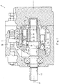
- the hydraulic pump 1 shown in Fig. 1 is a so-called variable displacement swash plate pump and includes a casing 11, a rotating shaft 12, a cylinder block 13, a plurality of pistons 2, a plurality of shoes 15, a swash plate 16, and a valve plate 17.
- the casing 11 is configured to accommodate the components 2 and 12 to 17, and one of end portions of the rotating shaft 12 projects from the casing 11.
- Bearings 18 and 19 are provided at a portion, close to the one end portion, of the rotating shaft 12 and the other end portion of the rotating shaft 12, respectively.
- the rotating shaft 12 is supported by the casing 11 through the bearings 18 and 19 so as to be rotatable.
- the cylinder block 13 is inserted through a portion, close to the other end portion, of the rotating shaft 12.
- the cylinder block 13 is formed in a substantially cylindrical shape.
- the cylinder block 13 is coaxially coupled (for example, splined) to the rotating shaft 12 so as not to be rotatable relative to the rotating shaft 12. Therefore, the cylinder block 13 rotates around an axis L1 integrally with the rotating shaft 12.
- the cylinder block 13 includes a plurality of cylinder chambers 20.
- the plurality of cylinder chambers 20 are arranged at regular intervals in a circumferential direction around the axis L1.
- Each of the cylinder chambers 20 is a hole that is open at one end side of the cylinder block 13 and extends in parallel with the axis L1.
- the pistons 2 are inserted into the respective cylinder chambers 20 through the openings.
- Each of the pistons 2 is a so-called female piston and is formed in a substantially cylindrical shape.
- a hollow portion 21 and a concave spherical portion 22 are formed at both respective end portions of the piston 2.
- the hollow portion 21 is a cylindrical portion that is open at a tip end of the piston 2 and extends toward a base end of the piston 2 from the tip end.
- the concave spherical portion 22 is a portion that is open at the base end of the piston 2 and is formed in a partially spherical shape.
- the hollow portion 21 and the concave spherical portion 22 are formed on an axis L2 of the piston 2 and are arranged away from each other in an axial direction (i.e., arranged at the tip end side and the base end side, respectively).
- An oil passage 23 is formed between the hollow portion 21 and the concave spherical portion 22, and the hollow portion 21 and the concave spherical portion 22 communicate with each other through the oil passage 23.
- the shoes 15 each having a convex spherical portion are attached to the respective pistons 2 configured as above.
- Each of the shoes 15 includes a spherical joint portion (convex spherical portion) 15a and a base body portion 15b.
- a steel ball that is the spherical joint portion 15a is formed in a substantially spherical shape and is formed based on, for example, ball grades G3 to G100 showing "Form and Surface Roughness Tolerances" of JIS B 1501 defining steel balls for rolling bearings.
- the spherical joint portion 15a having such shape is fitted in the concave spherical portion 22 of the piston 2 to be subjected to caulking.
- the spherical joint portion 15a rotates around a center point C1 of the concave spherical portion 22.
- the spherical joint portion 15a is formed integrally with the base body portion 15b.
- the base body portion 15b is formed in a substantially circular plate shape, and the spherical joint portion 15a is integrally formed on one of thickness-direction surfaces of the base body portion 15b.
- the other thickness-direction surface of the base body portion 15b is formed to be flat and is pressed against the swash plate 16.
- the swash plate 16 is a substantially annular plate and is arranged in the casing 11 with the rotating shaft 12 inserted into an inner hole of the swash plate 16.
- One of thickness-direction surfaces of the swash plate 16 is formed to be flat and forms a supporting surface 16a.
- the supporting surface 16a faces one of end surfaces of the cylinder block 13 so as to be inclined relative to the one end surface, and the base body portions 15b of the plurality of shoes 15 are arranged on the supporting surface 16a at intervals in the circumferential direction.
- a retainer plate 24 is provided at the rotating shaft 12 so as to press the plurality of shoes 15 against the supporting surface 16a.
- the retainer plate 24 is formed in a substantially annular shape, and the rotating shaft 12 is inserted through an inner hole of the retainer plate 24. Further, the retainer plate 24 includes a plurality of holes arranged at intervals in the circumferential direction. The plurality of holes of the retainer plate 24 are formed so as to correspond to the plurality of shoes 15 arranged on the supporting surface 16a, and the base body portions 15b of the shoes 15 are fitted in the respective holes of the retainer plate 24.
- the base body portion 15b includes a flange 15c that is an outer peripheral portion and is formed at a portion close to the swash plate 16 (i.e., at a portion close to the other surface) so as to have a larger diameter than the hole.
- the flange 15c is sandwiched by the retainer plate 24 and the swash plate 16.
- the rotating shaft 12 includes a spherical bushing 12a at a position where the retainer plate 24 is provided.
- the retainer plate 24 fits the spherical bushing 12a and is held by an outer peripheral surface of the spherical bushing 12a.
- the spherical bushing 12a is coupled (for example, splined) to the rotating shaft 12 so as not to be rotatable relative to the rotating shaft 12 and is biased toward the swash plate 16 by a cylinder spring (not shown). With this, the plurality of shoes 15 are pressed against the supporting surface 16a by the retainer plate 24.
- the plurality of shoes 15 rotate around the axis L1 on the supporting surface 16a.
- the supporting surface 16a is inclined relative to one end surface of the cylinder block 13, so that when the plurality of shoes 15 rotate around the axis L1, each of the shoes 15 approaches to and separates from the end surface of the cylinder block 13. With this, the pistons 2 attached to the shoes 15 reciprocate in the cylinder chambers 20 while rotating around the axis L1.
- a plurality of cylinder ports 25 are formed at the other end side of the cylinder block 13.
- the cylinder ports 25 are formed so as to correspond to the cylinder chambers 20 one to one.
- the plurality of cylinder ports 25 include respective openings at the other end of the cylinder block 13, and the openings are arranged at intervals in the circumferential direction around the axis L1.
- the valve plate 17 is provided at the other end of the cylinder block 13.
- the valve plate 17 is formed in a substantially circular plate shape.
- the rotating shaft 12 is inserted through the valve plate 17 so as to be rotatable relative to the valve plate 17.
- the valve plate 17 is fixed to the casing 11 with one of thickness-direction surfaces thereof contacting the other end of the cylinder block 13.
- the valve plate 17 includes an inlet port 17a and an outlet port 17b.
- Each of the inlet port 17a and the outlet port 17b is a hole that penetrates the valve plate 17 in a thickness direction and extends in a circumferential direction.
- the inlet port 17a and the outlet port 17b are arranged so as to be spaced apart from each other in the circumferential direction.
- the inlet port 17a and the outlet port 17b are arranged so as to correspond to the plurality of cylinder ports 25.
- Fig. 1 shows that the cylinder port 25 at a bottom dead center and the cylinder port 25 at a top dead center are coupled to the ports 17a and 17b, respectively.
- the port to which the cylinder port 25 is connected switches from the inlet port 17a to the outlet port 17b in the vicinity of the bottom dead center (position at a lower side in Fig. 1 ) and switches from the outlet port 17b to the inlet port 17a in the vicinity of the top dead center (position at an upper side in Fig. 1 ).
- the hydraulic pump 1 when the rotating shaft 12 rotates, the plurality of pistons 2 reciprocate in the respective cylinder chambers 20. With this, the operating oil is sucked through the inlet port 17a to the cylinder chamber 20, and the operating oil in the cylinder chamber 20 is ejected through the outlet port 17b. A flow rate of the operating oil ejected through the port 17b changes depending on an angle of the swash plate 16.
- the hydraulic pump 1 includes a servo mechanism 26.
- the servo mechanism 26 is configured to be able to tilt the swash plate 16 around the axis L2.
- a stroke amount of the piston 2 changes by the tilting of the swash plate 16. With this, the amount of operating oil ejected through the outlet port 17b (i.e., a pump capacity) can be changed.
- a female piston is used as the piston 2 as shown in Fig. 2 .
- the piston 2 is formed by forging using a low-strength material such as SCM415 or carbon steel containing 0.2% of carbon. More specifically, the entire piston 2 including the hollow portion 21, the concave spherical portion 22, and the oil passage 23 is formed by cold forging with a press machine or the like. After that, an outer peripheral surface of the piston 2 is subjected to normalizing, cutting work, polishing, and a hardening treatment (such as a gas nitrocarburizing treatment or a salt-bath nitrocarburizing treatment).
- the hollow portion 21, the concave spherical portion 22, and the oil passage 23 that are inner peripheral surfaces of the piston 2 are formed only by cold forging.
- predetermined shapes of the hollow portion 21, the concave spherical portion 22, and the oil passage 23 which are internal shapes of the piston 2 are designed. With this, the internal shapes of the piston 2 can be formed only by forging at a practical level. Therefore, the present invention can realize the piston 2 capable of being produced at low cost while securing durability.
- especially excellent shapes of the hollow portion 21, the concave spherical portion 22, and the oil passage 23 will be explained.
- the hollow portion 21 is formed in a cylindrical shape as described above and includes an inner peripheral surface 21a and a bottom surface 21b.
- the inner peripheral surface 21a is formed around an axis L3 of the piston 2, and the bottom surface 21b is formed so as to be perpendicular to the axis L3.
- the inner peripheral surface 21a is continuous with the bottom surface 21b at the base end side thereof and includes a corner portion 21c continuous with the bottom surface 21b.
- the corner portion 21c is formed so as to curve and taper toward the bottom surface 21b.
- the corner portion 21c is formed in a substantially quarter oval shape (long circular-arc shape) that is vertically long in a direction in which the axis L3 extends.
- the corner portion 21c is formed such that a ratio of a short axis b to a long axis a, i.e., an ellipticity b/a falls within a range of not less than 0.3 and not more than 0.7. Since the corner portion 21c is formed in a substantially quarter oval shape as above, pressure concentration can be made lower than a case where round chamfering of the corner portion 21c is performed. Therefore, even if the corner portion 21c has a curved surface of a smaller oval shape, the strength of the piston can obtain a practical level.
- the hollow portion 21 formed only by forging can secure durability, and a manufacturing cost for the piston 2 and the hydraulic pump 1 can be reduced by forming the hollow portion 21 only by forging. Further, since a forming load at the time of forging can be reduced, forging formability improves.
- the vicinity of the opening of the concave spherical portion 22 i.e., an upper portion of the concave spherical portion 22
- a bottom side of the concave spherical portion 22 i.e., a lower portion of the concave spherical portion 22
- the concave spherical portion 22 When the spherical joint portion 15a is fitted in the concave spherical portion 22, and the outer peripheral surface of the concave spherical portion 22 is pushed inward and caulked, the concave spherical portion 22 is formed to have a partially spherical shape. With this, the spherical joint portion 15a of the shoe 15 is wrapped by the concave spherical portion 22, is rotatable relative to the piston 2, and does not separate from the piston 2.
- a concave spherical surface 22a that is an inner surface of the concave spherical portion 22 is formed only by forging so as to correspond to an outer surface (i.e., a spherical surface) of the spherical joint portion 15a.
- a concave spherical surface 22a that is an inner surface of the concave spherical portion 22 is formed only by forging so as to correspond to an outer surface (i.e., a spherical surface) of the spherical joint portion 15a.
- a center (i.e., the center point C1) of the concave spherical surface 22a is located on the axis L3 of the piston 2.
- a region where an angle ⁇ to the central axis (axis L3) of the piston 2 is not more than 90° is a semi-spherical surface region 22b of the concave spherical surface 22a.
- a region where an angle ⁇ between the axis L3 and a straight line connecting the center (center point C1) of the concave spherical surface 22a and a surface of the concave spherical surface 22a is not more than 90° is the semi-spherical surface region 22b of the concave spherical surface 22a.
- the semi-spherical surface region 22b of the concave spherical surface 22a is a region where the angle ⁇ to the central axis (axis L3) of the piston 2 when the oil passage 23 is formed at the piston 2 is not more than 90°.
- the master ball 31 is a basis of the steel ball of the spherical joint portion 15a, and the steel ball of the spherical joint portion 15a is formed based on the same standard and conditions as the master ball 31.
- the master ball 31 is formed to have a set diameter D with tolerance of, for example, a predetermined size or less (such as ⁇ 5 ⁇ m or less).
- paint for example, bearing red
- a predetermined thickness for example, 10 ⁇ m or less
- predetermined pressing force for example, 1 to 5 kgf
- a portion where the paint is transferred is determined as a portion where the concave spherical surface 22a and the spherical joint portion 15a contact each other.
- an area (transfer area) of a region where the paint is transferred is 40% or more of the entire area of the semi-spherical surface region 22b, a contact area is regarded as 40% or more.
- the piston 2 is formed such that the contact area that is an area of contact between the semi-spherical surface region 22b of the concave spherical surface 22a and the master ball 31 is 40% or more of the entire area of the semi-spherical surface region 22b.
- the contact area is set to 40% or more. Therefore, when the piston 2 pushes the operating oil or when the piston 2 is pushed by the operating oil, a load from the spherical joint portion 15a can be received by a wide region of the concave spherical surface 22a, and surface pressure (load per unit area) acting on the concave spherical surface 22a can be reduced. With this, even when a high load acts on the piston 2 for the purpose of ejecting high-pressure (for example, 28MPa) operating oil, the concave spherical portion 22 is not damaged, and the spherical joint portion 15a can smoothly move in the concave spherical portion 22. Therefore, the concave spherical surface 22a formed only by forging can bear high pressure, and the manufacturing cost for the piston 2 and the hydraulic pump 1 can be reduced by forming the concave spherical surface 22a only by forging.
- high-pressure for example, 28MPa
- a region where the angle ⁇ to the central axis (axis L3) of the piston 2 is not less than 35° and not more than 50° is a first ring-shaped region 22c.
- a region where the angle ⁇ between the axis L3 and the straight line connecting the center of the concave spherical surface 22a and the surface of the concave spherical surface 22a is not less than 35° and not more than 50° is the first ring-shaped region 22c.
- the piston 2 is formed such that the contact area (i.e., contact in the circumferential direction) is 50% or more of the entire area of the first ring-shaped region 22c.
- the piston 2 is formed such that the transfer area when the paint is transferred by pressing the master ball 31 against the concave spherical surface 22a under the above-described conditions is 50% or more of the entire area of the first ring-shaped region 22c.
- the contact area at the first ring-shaped region 22c is set to 50% or more, an axial load applied from the spherical joint portion 15a by the reciprocating movement can be received by a wide surface of a bottom portion (ring-shaped surface in the vicinity of the axis L3) of the concave spherical surface 22a, and the surface pressure acting on the concave spherical surface 22a can be reduced.
- the spherical joint portion 15a can be supported in the axial direction in a state where the surface pressure acting on the concave spherical surface 22a of the piston 2 is low. Therefore, even when a further high load acts on the piston 2, the spherical joint portion 15a can smoothly slide, and the piston 2 and the hydraulic pump 1 can deal with further high ejection pressure.
- a region formed between a ring-shaped first boundary 22f and a ring-shaped second boundary 22g is a second ring-shaped region 22d.
- the ring-shaped first boundary 22f is a portion where the oil passage 23 and the concave spherical surface 22a are connected to each other. That is, the ring-shaped first boundary 22f is a border line between the oil passage 23 and the concave spherical surface 22a.
- the ring-shaped second boundary 22g is a portion where the concave spherical surface 22a intersects with a straight line that connects the center of the concave spherical surface 22a and the surface of the concave spherical surface 22a, has the angle ⁇ of 35° to the central axis (axis L3) of the piston, and is rotated around the axis L3. That is, the ring-shaped second boundary 22g is a border line defined at a position where the angle ⁇ is 35° on the concave spherical surface 22a.
- the piston 2 is formed such that the area of contact between the master ball 31 and the second ring-shaped region 22d of the concave spherical surface 22a is 60% or more of the entire area of the second ring-shaped region 22d.
- the piston 2 is formed such that the transfer area when the paint is transferred by pressing the master ball 31 against the concave spherical surface 22a under the above-described conditions is 60% or more of the entire area of the second ring-shaped region 22d.
- the contact in the circumferential direction of the second ring-shaped region 22d is set to 60% or more, partial contact of the spherical joint portion 15a with the concave spherical surface 22a can be suppressed. With this, the surface pressure acting on the concave spherical surface 22a can be uniformized, and the piston 2 and the hydraulic pump 1 can deal with further high ejection pressure.
- a region where the angle ⁇ to the central axis (axis L3) of the piston 2 is not less than 33° and not more than 35° is a third ring-shaped region 22e.
- a region where the angle ⁇ between the axis L3 and the straight line connecting the center of the concave spherical surface 22a and the surface of the concave spherical surface 22a is not less than 33° and not more than 35° is the third ring-shaped region 22e.
- the piston 2 is formed such that the contact area (i.e., contact in the circumferential direction) is 60% or more of the entire area of the third ring-shaped region 22e.
- the piston 2 is formed such that the transfer area when the paint is transferred by pressing the master ball 31 against the concave spherical surface 22a under the above-described conditions is 60% or more of the entire area of the third ring-shaped region 22e.
- the contact in the circumferential direction of the third ring-shaped region 22e is set to 60% or more, partial contact of the spherical joint portion 15a with the concave spherical surface 22a can be suppressed.
- the surface pressure acting on the concave spherical surface 22a can be uniformized, and the piston 2 and the hydraulic pump 1 can deal with further high ejection pressure.
- the oil passage 23 is a through hole through which the hollow portion 21 and the concave spherical portion 22 communicate with each other and which has a substantially circular section.
- An aspect ratio that is a ratio of a hole diameter r to a depth d falls within a range of not less than 0.7 and not more than 1.2.
- connection portion 23a where the oil passage 23 and the concave spherical portion 22 are connected to each other is subjected to round chamfering.
- the connection portion 23a has a fillet shape.
- the connection portion 23a is formed so as to spread toward the concave spherical portion 22. This can prevent a case where the spherical joint portion 15a that slides and rotates in the concave spherical portion 22 contacts the connection portion 23a, this inhibits the rotation of the spherical joint portion 15a. With this, sliding resistance of the spherical joint portion 15a can be reduced, and the piston 2 and the hydraulic pump 1 can deal with further high pressure.
- the liquid-pressure rotating device is the hydraulic pump 1.
- the liquid-pressure rotating device may be a hydraulic motor.
- An operating liquid sucked and ejected is not limited to the operating oil and may be a liquid such as water.
- the hydraulic pump 1 is the variable displacement swash plate pump.
- the hydraulic pump 1 may be a fixed displacement swash plate pump.
- a device to which the piston 2 is applied is not limited to the liquid-pressure rotating device such as the hydraulic pump 1 and may be applied to an actuator or the like.
- the piston 2 does not necessarily have to include all the characteristic shapes of the hollow portion 21, the concave spherical portion 22, and the oil passage 23. Excellent operational advantages can be obtained by each characteristic shape, and further excellent operational advantages can be obtained by the above-described combination of the characteristic shapes.
Landscapes
- Engineering & Computer Science (AREA)
- Mechanical Engineering (AREA)
- General Engineering & Computer Science (AREA)
- Reciprocating Pumps (AREA)
- Hydraulic Motors (AREA)
Claims (5)
- Kolben (2), umfassend:einen konkaven sphärischen Abschnitt (22), der an einem von Endabschnitten des Kolbens gebildet ist und einen Kugelgelenkabschnitt (15a) eines Schuhs (15) einer Flüssigkeitsdruckdrehvorrichtung (1) stützt, sodass der Kugelgelenkabschnitt schiebbbar und drehbar ist;einen zylindrischen hohlen Abschnitt (21), der an dem anderen Endabschnitt des Kolbens gebildet ist; undeinen Öldurchlass (23), der zwischen dem konkaven sphärischen Abschnitt und dem hohlen Abschnitt gebildet ist, wobei der konkave sphärische Abschnitt und der hohle Abschnitt durch den Öldurchlass miteinander kommunizieren, wobei:der konkave sphärische Abschnitt eine konkave sphärische Oberfläche (22a) beinhaltet; unddie konkave sphärische Oberfläche ein hemisphärisches Oberflächengebiet (22b) beinhaltet;dadurch gekennzeichnet, dass ein Verbindungsabschnitt, wo der konkave sphärische Abschnitt und der Öldurchlass miteinander verbunden sind, gebildet ist, um sich zu dem konkaven sphärischen Abschnitt auszuweiten; unddadurch, dass die konkave sphärische Oberfläche durch Schmieden gebildet wird.
- Kolben nach Anspruch 1, wobei:die konkave sphärische Oberfläche (22a) ein erstes ringförmiges Gebiet (22c) in einem Bereich beinhaltet, wo ein Winkel zu einer Mittelachse (L3) des Kolbens (2) nicht kleiner als 35° und nicht größer als 50° ist; unddas erste ringförmige Gebiet so gebildet ist, dass eine Kontaktfläche zwischen dem ersten ringförmigen Gebiet und einer Hauptkugel (31), die eine Basis des Kugelgelenkabschnitts (15a) ist, 50% oder mehr einer Gesamtfläche des ersten ringförmigen Gebiets ist.
- Kolben nach Anspruch 1 oder 2, wobei:die konkave sphärische Oberfläche (22a) ein zweites ringförmiges Gebiet (22d) zwischen einem ringförmigen ersten Rand (22f) und einem ringförmigen zweiten Rand (22g) gebildet beinhaltet;der erste Rand eine Grenzlinie zwischen dem Öldurchlass (23) und der konkaven sphärischen Oberfläche (22a) ist;der zweite Rand eine Grenzlinie ist, die bei einer Position definiert ist, wo ein Winkel zwischen einer Mittelachse (L3) des Kolbens (2) und einer geraden Linie, die einen Mittelpunkt der konkaven sphärischen Oberfläche und eine Oberfläche der konkaven sphärischen Oberfläche verbindet, 35° ist; unddas zweite ringförmige Gebiet so gebildet ist, dass eine Kontaktfläche zwischen dem zweiten ringförmigen Gebiet und einer Hauptkugel (31), die eine Basis des Kugelgelenkabschnitts (15a) ist, 60% oder mehr einer Gesamtfläche des zweiten ringförmigen Gebiets ist.
- Kolben nach einem der Ansprüche 1 bis 3, wobei:der Öldurchlass (23) durch Schmieden gebildet wird; undein Verhältnis eines Lochdurchmessers (r) des Öldurchlasses zu einer Länge (d) des Öldurchlasses nicht niedriger als 0,7 und nicht höher als 1,2 ist.
- Flüssigkeitsdruckdrehvorrichtung (1), umfassend:eine Vielzahl von Kolben (2), wobei jeder der Kolben nach einem der Ansprüche 1 bis 4 ist;eine Taumelscheibe (16);eine Vielzahl von Schuhen (15), die von der Taumelscheibe gestützt werden, um schiebbar zu sein, wobei die Schuhe jeweilige konvexe sphärische Abschnitte (15a) an jeweiligen konkaven sphärischen Abschnitten (22) der Kolben befestigt beinhalten; undeinen Zylinderblock (13), in den die Vielzahl von Kolben eingesetzt werden, um sich hin- und herzubewegen.
Applications Claiming Priority (2)
| Application Number | Priority Date | Filing Date | Title |
|---|---|---|---|
| JP2015095798A JP5947954B1 (ja) | 2015-05-08 | 2015-05-08 | ピストン、及びそれを備える液圧回転機械 |
| PCT/JP2016/002244 WO2016181638A1 (ja) | 2015-05-08 | 2016-05-02 | ピストン、及びそれを備える液圧回転機械 |
Publications (3)
| Publication Number | Publication Date |
|---|---|
| EP3296568A1 EP3296568A1 (de) | 2018-03-21 |
| EP3296568A4 EP3296568A4 (de) | 2019-05-08 |
| EP3296568B1 true EP3296568B1 (de) | 2021-07-14 |
Family
ID=56329536
Family Applications (1)
| Application Number | Title | Priority Date | Filing Date |
|---|---|---|---|
| EP16792367.1A Active EP3296568B1 (de) | 2015-05-08 | 2016-05-02 | Kolben und hydraulische drehmaschine damit |
Country Status (6)
| Country | Link |
|---|---|
| US (1) | US10527028B2 (de) |
| EP (1) | EP3296568B1 (de) |
| JP (1) | JP5947954B1 (de) |
| KR (1) | KR101974942B1 (de) |
| CN (1) | CN107532577B (de) |
| WO (1) | WO2016181638A1 (de) |
Cited By (1)
| Publication number | Priority date | Publication date | Assignee | Title |
|---|---|---|---|---|
| DE102022203309A1 (de) | 2022-04-04 | 2023-10-05 | Robert Bosch Gesellschaft mit beschränkter Haftung | Hydrostatische Kolbenmaschine mit zweigeteilter Stellkammer |
Families Citing this family (2)
| Publication number | Priority date | Publication date | Assignee | Title |
|---|---|---|---|---|
| CN110617189B (zh) * | 2019-11-21 | 2020-04-10 | 长沙桑铼特农业机械设备有限公司 | 手自双控式一体泵马达 |
| KR102945799B1 (ko) * | 2020-11-26 | 2026-03-27 | 엘지전자 주식회사 | 응축기 팽창 장치 및 이를 포함하는 터보 칠러 |
Family Cites Families (26)
| Publication number | Priority date | Publication date | Assignee | Title |
|---|---|---|---|---|
| GB1177633A (en) * | 1966-02-04 | 1970-01-14 | Boulton Aircraft Ltd | Ball Joint Assembly. |
| JPS5114284B1 (de) * | 1967-12-28 | 1976-05-08 | ||
| JPS531304A (en) * | 1976-06-28 | 1978-01-09 | Ntn Toyo Bearing Co Ltd | Plunger and method of manufacturing same |
| JPS5333406A (en) * | 1976-09-10 | 1978-03-29 | Toyo Bearing Mfg Co | Plunger shoes and method of producing the same |
| DE3714892A1 (de) * | 1986-05-08 | 1987-11-12 | Honda Motor Co Ltd | Verfahren zum herstellen einer schwenkverbindung zum abstuetzen eines kipphebels eines ventilzuges einer brennkraftmaschine |
| JPS63112280U (de) * | 1987-01-13 | 1988-07-19 | ||
| JPH0617000Y2 (ja) * | 1987-02-25 | 1994-05-02 | 株式会社小松製作所 | 斜板式ポンプ・モ−タ |
| JPH07109973A (ja) * | 1993-10-15 | 1995-04-25 | Honda Motor Co Ltd | 斜板式油圧装置 |
| US5490446A (en) * | 1994-03-22 | 1996-02-13 | Caterpillar Inc. | Apparatus and method for a piston assembly |
| DE69511872T2 (de) * | 1994-07-08 | 2000-05-04 | Danfoss A/S, Nordborg | Kolben mit gleitschuh für hydraulischen kolbenmotor |
| DE19712838C2 (de) * | 1997-03-26 | 1999-03-18 | Brueninghaus Hydromatik Gmbh | Verfahren zum Herstellen einer Kugelgelenkverbindung |
| JP2000220567A (ja) * | 1999-01-27 | 2000-08-08 | Hitachi Constr Mach Co Ltd | 斜板型ピストンポンプ・モータのピストン |
| JP2000230476A (ja) * | 1999-02-08 | 2000-08-22 | Hitachi Constr Mach Co Ltd | 斜板式液圧回転機 |
| JP3474796B2 (ja) * | 1999-03-03 | 2003-12-08 | 日立建機株式会社 | 斜板型液圧回転機用シューの製造方法 |
| US6318242B1 (en) * | 1999-10-26 | 2001-11-20 | Sauer-Danfoss Inc. | Filled hydraulic piston and method of making the same |
| US6293185B1 (en) * | 2000-02-28 | 2001-09-25 | Sauer-Danfoss Inc. | Piston for a hydrostatic cylinder block |
| JP3777942B2 (ja) * | 2000-03-15 | 2006-05-24 | 株式会社豊田自動織機 | 圧縮機用中空ピストンの製造方法 |
| US6338293B1 (en) * | 2000-06-30 | 2002-01-15 | Sauer-Danfoss Inc. | Reduced oil volume piston assembly for a hydrostatic unit |
| FR2854089B1 (fr) * | 2003-04-23 | 2006-05-19 | Semt Pielstick | Procede de fabrication d'un piston, outillage pour la mise en oeuvre de ce procede et piston ainsi obtenu |
| JP3815462B2 (ja) * | 2003-08-08 | 2006-08-30 | 大豊工業株式会社 | シュー |
| DE10356155B4 (de) * | 2003-12-02 | 2006-06-14 | Brueninghaus Hydromatik Gmbh | Hydrostatisches Antriebssystem mit pumpenseitiger Hydraulikfluidmengenteilung |
| EP1750009B1 (de) * | 2005-08-05 | 2019-07-03 | Poclain Hydraulics | Kugelgelenk für eine hydrostatische Maschine |
| JP5164433B2 (ja) * | 2007-05-29 | 2013-03-21 | サンデン株式会社 | 圧縮機用ピストンの製造方法 |
| JP2014152753A (ja) | 2013-02-13 | 2014-08-25 | Hitachi Constr Mach Co Ltd | アキシャルピストン式液圧ポンプ |
| CH707789A1 (de) * | 2013-03-25 | 2014-09-30 | Liebherr Machines Bulle Sa | Kolben für eine Axialkolbenmaschine. |
| DE102013211893A1 (de) * | 2013-06-24 | 2014-12-24 | Robert Bosch Gmbh | Hohlkolben für eine Schrägscheibenmaschine und Schrägscheibenmaschine |
-
2015
- 2015-05-08 JP JP2015095798A patent/JP5947954B1/ja active Active
-
2016
- 2016-05-02 KR KR1020177034539A patent/KR101974942B1/ko active Active
- 2016-05-02 CN CN201680025191.4A patent/CN107532577B/zh active Active
- 2016-05-02 WO PCT/JP2016/002244 patent/WO2016181638A1/ja not_active Ceased
- 2016-05-02 EP EP16792367.1A patent/EP3296568B1/de active Active
- 2016-05-02 US US15/572,755 patent/US10527028B2/en active Active
Cited By (1)
| Publication number | Priority date | Publication date | Assignee | Title |
|---|---|---|---|---|
| DE102022203309A1 (de) | 2022-04-04 | 2023-10-05 | Robert Bosch Gesellschaft mit beschränkter Haftung | Hydrostatische Kolbenmaschine mit zweigeteilter Stellkammer |
Also Published As
| Publication number | Publication date |
|---|---|
| KR101974942B1 (ko) | 2019-05-03 |
| KR20180004194A (ko) | 2018-01-10 |
| EP3296568A1 (de) | 2018-03-21 |
| EP3296568A4 (de) | 2019-05-08 |
| JP5947954B1 (ja) | 2016-07-06 |
| US10527028B2 (en) | 2020-01-07 |
| CN107532577A (zh) | 2018-01-02 |
| CN107532577B (zh) | 2020-05-15 |
| JP2016211431A (ja) | 2016-12-15 |
| WO2016181638A1 (ja) | 2016-11-17 |
| US20180119683A1 (en) | 2018-05-03 |
Similar Documents
| Publication | Publication Date | Title |
|---|---|---|
| US20160327015A1 (en) | Hydraulic pump/motor | |
| CN120193978A (zh) | 用于径向活塞式压缩机的活塞-缸组件以及径向活塞式压缩机 | |
| JP2010037997A (ja) | 燃料供給ポンプ | |
| EP3296568B1 (de) | Kolben und hydraulische drehmaschine damit | |
| US20160273653A1 (en) | Piston | |
| WO2008026501A1 (fr) | Machine à rotation hydraulique | |
| US7832995B2 (en) | Variable displacement vane pump and method of manufacturing the same | |
| US20090199705A1 (en) | Axial piston machine and control plate for an axial piston machine | |
| EP3364026B1 (de) | Pumpe mit variabler verdrängung | |
| US10794185B2 (en) | Cylinder block and swash plate type liquid-pressure rotating apparatus including same | |
| US4642032A (en) | Axial piston pump including ball piston | |
| CN101270739A (zh) | 轴向柱塞式液压马达或泵 | |
| US20190055931A1 (en) | Hydraulic rotary machine | |
| JP6276911B2 (ja) | 液圧回転機 | |
| CN103154495B (zh) | 尤其是在燃料高压泵的泵活塞的驱动器中的、具有可旋转地支承在其中的滚子的轴承元件 | |
| JP6023907B1 (ja) | ピストン、及びそれを備える液圧回転機械 | |
| CN109139449B (zh) | 静液压的挤压机、用于静液压的挤压机的活塞以及用于静液压的挤压机的缸筒 | |
| EP3351793A1 (de) | Hydraulische rotationsmaschine und ventilplatte dafür | |
| EP2914850B1 (de) | Krimpfreie kolbenschuh-anordnung | |
| EP1087136B1 (de) | Taumelscheibenkompressorkopf mit Fase | |
| EP2423505B1 (de) | Axiale Hilfsnockenanordnung für Kolbenpumpe | |
| JP2009127538A (ja) | 斜板式油圧ポンプ | |
| EP3495657B1 (de) | Hydraulische rotationsmaschine vom axialkolbentyp | |
| CN201190641Y (zh) | 轴向柱塞式液压马达或泵 | |
| JP2025145719A (ja) | アキシャルピストン式液圧回転機 |
Legal Events
| Date | Code | Title | Description |
|---|---|---|---|
| STAA | Information on the status of an ep patent application or granted ep patent |
Free format text: STATUS: THE INTERNATIONAL PUBLICATION HAS BEEN MADE |
|
| PUAI | Public reference made under article 153(3) epc to a published international application that has entered the european phase |
Free format text: ORIGINAL CODE: 0009012 |
|
| STAA | Information on the status of an ep patent application or granted ep patent |
Free format text: STATUS: REQUEST FOR EXAMINATION WAS MADE |
|
| 17P | Request for examination filed |
Effective date: 20171208 |
|
| AK | Designated contracting states |
Kind code of ref document: A1 Designated state(s): AL AT BE BG CH CY CZ DE DK EE ES FI FR GB GR HR HU IE IS IT LI LT LU LV MC MK MT NL NO PL PT RO RS SE SI SK SM TR |
|
| AX | Request for extension of the european patent |
Extension state: BA ME |
|
| DAV | Request for validation of the european patent (deleted) | ||
| DAX | Request for extension of the european patent (deleted) | ||
| RIC1 | Information provided on ipc code assigned before grant |
Ipc: F03C 1/253 20060101ALI20181031BHEP Ipc: F04B 1/20 20060101ALI20181031BHEP Ipc: F04B 1/22 20060101AFI20181031BHEP |
|
| RIC1 | Information provided on ipc code assigned before grant |
Ipc: F04B 1/20 20060101ALI20181123BHEP Ipc: F04B 1/22 20060101AFI20181123BHEP Ipc: F03C 1/253 20060101ALI20181123BHEP |
|
| A4 | Supplementary search report drawn up and despatched |
Effective date: 20190409 |
|
| RIC1 | Information provided on ipc code assigned before grant |
Ipc: F03C 1/253 20060101ALI20190403BHEP Ipc: F04B 1/20 20060101ALI20190403BHEP Ipc: F04B 1/22 20060101AFI20190403BHEP Ipc: F04B 1/04 20060101ALI20190403BHEP |
|
| REG | Reference to a national code |
Ref country code: DE Ref legal event code: R079 Ref document number: 602016060656 Country of ref document: DE Free format text: PREVIOUS MAIN CLASS: F04B0001220000 Ipc: F04B0001207800 |
|
| GRAP | Despatch of communication of intention to grant a patent |
Free format text: ORIGINAL CODE: EPIDOSNIGR1 |
|
| STAA | Information on the status of an ep patent application or granted ep patent |
Free format text: STATUS: GRANT OF PATENT IS INTENDED |
|
| RIC1 | Information provided on ipc code assigned before grant |
Ipc: F04B 1/22 20060101ALI20210202BHEP Ipc: F04B 1/0408 20200101ALI20210202BHEP Ipc: F04B 1/2078 20200101AFI20210202BHEP |
|
| INTG | Intention to grant announced |
Effective date: 20210224 |
|
| GRAS | Grant fee paid |
Free format text: ORIGINAL CODE: EPIDOSNIGR3 |
|
| GRAA | (expected) grant |
Free format text: ORIGINAL CODE: 0009210 |
|
| STAA | Information on the status of an ep patent application or granted ep patent |
Free format text: STATUS: THE PATENT HAS BEEN GRANTED |
|
| AK | Designated contracting states |
Kind code of ref document: B1 Designated state(s): AL AT BE BG CH CY CZ DE DK EE ES FI FR GB GR HR HU IE IS IT LI LT LU LV MC MK MT NL NO PL PT RO RS SE SI SK SM TR |
|
| REG | Reference to a national code |
Ref country code: GB Ref legal event code: FG4D |
|
| REG | Reference to a national code |
Ref country code: IE Ref legal event code: FG4D |
|
| REG | Reference to a national code |
Ref country code: DE Ref legal event code: R096 Ref document number: 602016060656 Country of ref document: DE |
|
| REG | Reference to a national code |
Ref country code: AT Ref legal event code: REF Ref document number: 1410860 Country of ref document: AT Kind code of ref document: T Effective date: 20210815 |
|
| REG | Reference to a national code |
Ref country code: LT Ref legal event code: MG9D |
|
| REG | Reference to a national code |
Ref country code: NL Ref legal event code: MP Effective date: 20210714 |
|
| REG | Reference to a national code |
Ref country code: AT Ref legal event code: MK05 Ref document number: 1410860 Country of ref document: AT Kind code of ref document: T Effective date: 20210714 |
|
| PG25 | Lapsed in a contracting state [announced via postgrant information from national office to epo] |
Ref country code: SE Free format text: LAPSE BECAUSE OF FAILURE TO SUBMIT A TRANSLATION OF THE DESCRIPTION OR TO PAY THE FEE WITHIN THE PRESCRIBED TIME-LIMIT Effective date: 20210714 Ref country code: RS Free format text: LAPSE BECAUSE OF FAILURE TO SUBMIT A TRANSLATION OF THE DESCRIPTION OR TO PAY THE FEE WITHIN THE PRESCRIBED TIME-LIMIT Effective date: 20210714 Ref country code: LT Free format text: LAPSE BECAUSE OF FAILURE TO SUBMIT A TRANSLATION OF THE DESCRIPTION OR TO PAY THE FEE WITHIN THE PRESCRIBED TIME-LIMIT Effective date: 20210714 Ref country code: AT Free format text: LAPSE BECAUSE OF FAILURE TO SUBMIT A TRANSLATION OF THE DESCRIPTION OR TO PAY THE FEE WITHIN THE PRESCRIBED TIME-LIMIT Effective date: 20210714 Ref country code: BG Free format text: LAPSE BECAUSE OF FAILURE TO SUBMIT A TRANSLATION OF THE DESCRIPTION OR TO PAY THE FEE WITHIN THE PRESCRIBED TIME-LIMIT Effective date: 20211014 Ref country code: NL Free format text: LAPSE BECAUSE OF FAILURE TO SUBMIT A TRANSLATION OF THE DESCRIPTION OR TO PAY THE FEE WITHIN THE PRESCRIBED TIME-LIMIT Effective date: 20210714 Ref country code: PT Free format text: LAPSE BECAUSE OF FAILURE TO SUBMIT A TRANSLATION OF THE DESCRIPTION OR TO PAY THE FEE WITHIN THE PRESCRIBED TIME-LIMIT Effective date: 20211115 Ref country code: NO Free format text: LAPSE BECAUSE OF FAILURE TO SUBMIT A TRANSLATION OF THE DESCRIPTION OR TO PAY THE FEE WITHIN THE PRESCRIBED TIME-LIMIT Effective date: 20211014 Ref country code: HR Free format text: LAPSE BECAUSE OF FAILURE TO SUBMIT A TRANSLATION OF THE DESCRIPTION OR TO PAY THE FEE WITHIN THE PRESCRIBED TIME-LIMIT Effective date: 20210714 Ref country code: FI Free format text: LAPSE BECAUSE OF FAILURE TO SUBMIT A TRANSLATION OF THE DESCRIPTION OR TO PAY THE FEE WITHIN THE PRESCRIBED TIME-LIMIT Effective date: 20210714 Ref country code: ES Free format text: LAPSE BECAUSE OF FAILURE TO SUBMIT A TRANSLATION OF THE DESCRIPTION OR TO PAY THE FEE WITHIN THE PRESCRIBED TIME-LIMIT Effective date: 20210714 |
|
| PG25 | Lapsed in a contracting state [announced via postgrant information from national office to epo] |
Ref country code: PL Free format text: LAPSE BECAUSE OF FAILURE TO SUBMIT A TRANSLATION OF THE DESCRIPTION OR TO PAY THE FEE WITHIN THE PRESCRIBED TIME-LIMIT Effective date: 20210714 Ref country code: LV Free format text: LAPSE BECAUSE OF FAILURE TO SUBMIT A TRANSLATION OF THE DESCRIPTION OR TO PAY THE FEE WITHIN THE PRESCRIBED TIME-LIMIT Effective date: 20210714 Ref country code: GR Free format text: LAPSE BECAUSE OF FAILURE TO SUBMIT A TRANSLATION OF THE DESCRIPTION OR TO PAY THE FEE WITHIN THE PRESCRIBED TIME-LIMIT Effective date: 20211015 |
|
| REG | Reference to a national code |
Ref country code: DE Ref legal event code: R097 Ref document number: 602016060656 Country of ref document: DE |
|
| PG25 | Lapsed in a contracting state [announced via postgrant information from national office to epo] |
Ref country code: DK Free format text: LAPSE BECAUSE OF FAILURE TO SUBMIT A TRANSLATION OF THE DESCRIPTION OR TO PAY THE FEE WITHIN THE PRESCRIBED TIME-LIMIT Effective date: 20210714 |
|
| PLBE | No opposition filed within time limit |
Free format text: ORIGINAL CODE: 0009261 |
|
| STAA | Information on the status of an ep patent application or granted ep patent |
Free format text: STATUS: NO OPPOSITION FILED WITHIN TIME LIMIT |
|
| PG25 | Lapsed in a contracting state [announced via postgrant information from national office to epo] |
Ref country code: SM Free format text: LAPSE BECAUSE OF FAILURE TO SUBMIT A TRANSLATION OF THE DESCRIPTION OR TO PAY THE FEE WITHIN THE PRESCRIBED TIME-LIMIT Effective date: 20210714 Ref country code: SK Free format text: LAPSE BECAUSE OF FAILURE TO SUBMIT A TRANSLATION OF THE DESCRIPTION OR TO PAY THE FEE WITHIN THE PRESCRIBED TIME-LIMIT Effective date: 20210714 Ref country code: RO Free format text: LAPSE BECAUSE OF FAILURE TO SUBMIT A TRANSLATION OF THE DESCRIPTION OR TO PAY THE FEE WITHIN THE PRESCRIBED TIME-LIMIT Effective date: 20210714 Ref country code: EE Free format text: LAPSE BECAUSE OF FAILURE TO SUBMIT A TRANSLATION OF THE DESCRIPTION OR TO PAY THE FEE WITHIN THE PRESCRIBED TIME-LIMIT Effective date: 20210714 Ref country code: CZ Free format text: LAPSE BECAUSE OF FAILURE TO SUBMIT A TRANSLATION OF THE DESCRIPTION OR TO PAY THE FEE WITHIN THE PRESCRIBED TIME-LIMIT Effective date: 20210714 Ref country code: AL Free format text: LAPSE BECAUSE OF FAILURE TO SUBMIT A TRANSLATION OF THE DESCRIPTION OR TO PAY THE FEE WITHIN THE PRESCRIBED TIME-LIMIT Effective date: 20210714 |
|
| 26N | No opposition filed |
Effective date: 20220419 |
|
| PG25 | Lapsed in a contracting state [announced via postgrant information from national office to epo] |
Ref country code: IT Free format text: LAPSE BECAUSE OF FAILURE TO SUBMIT A TRANSLATION OF THE DESCRIPTION OR TO PAY THE FEE WITHIN THE PRESCRIBED TIME-LIMIT Effective date: 20210714 |
|
| REG | Reference to a national code |
Ref country code: CH Ref legal event code: PL |
|
| REG | Reference to a national code |
Ref country code: BE Ref legal event code: MM Effective date: 20220531 |
|
| PG25 | Lapsed in a contracting state [announced via postgrant information from national office to epo] |
Ref country code: MC Free format text: LAPSE BECAUSE OF FAILURE TO SUBMIT A TRANSLATION OF THE DESCRIPTION OR TO PAY THE FEE WITHIN THE PRESCRIBED TIME-LIMIT Effective date: 20210714 Ref country code: LU Free format text: LAPSE BECAUSE OF NON-PAYMENT OF DUE FEES Effective date: 20220502 Ref country code: LI Free format text: LAPSE BECAUSE OF NON-PAYMENT OF DUE FEES Effective date: 20220531 Ref country code: CH Free format text: LAPSE BECAUSE OF NON-PAYMENT OF DUE FEES Effective date: 20220531 |
|
| PG25 | Lapsed in a contracting state [announced via postgrant information from national office to epo] |
Ref country code: IE Free format text: LAPSE BECAUSE OF NON-PAYMENT OF DUE FEES Effective date: 20220502 |
|
| PG25 | Lapsed in a contracting state [announced via postgrant information from national office to epo] |
Ref country code: BE Free format text: LAPSE BECAUSE OF NON-PAYMENT OF DUE FEES Effective date: 20220531 |
|
| PG25 | Lapsed in a contracting state [announced via postgrant information from national office to epo] |
Ref country code: HU Free format text: LAPSE BECAUSE OF FAILURE TO SUBMIT A TRANSLATION OF THE DESCRIPTION OR TO PAY THE FEE WITHIN THE PRESCRIBED TIME-LIMIT; INVALID AB INITIO Effective date: 20160502 |
|
| PG25 | Lapsed in a contracting state [announced via postgrant information from national office to epo] |
Ref country code: MK Free format text: LAPSE BECAUSE OF FAILURE TO SUBMIT A TRANSLATION OF THE DESCRIPTION OR TO PAY THE FEE WITHIN THE PRESCRIBED TIME-LIMIT Effective date: 20210714 Ref country code: CY Free format text: LAPSE BECAUSE OF FAILURE TO SUBMIT A TRANSLATION OF THE DESCRIPTION OR TO PAY THE FEE WITHIN THE PRESCRIBED TIME-LIMIT Effective date: 20210714 |
|
| PG25 | Lapsed in a contracting state [announced via postgrant information from national office to epo] |
Ref country code: MT Free format text: LAPSE BECAUSE OF FAILURE TO SUBMIT A TRANSLATION OF THE DESCRIPTION OR TO PAY THE FEE WITHIN THE PRESCRIBED TIME-LIMIT Effective date: 20210714 |
|
| PGFP | Annual fee paid to national office [announced via postgrant information from national office to epo] |
Ref country code: DE Payment date: 20250402 Year of fee payment: 10 |
|
| PGFP | Annual fee paid to national office [announced via postgrant information from national office to epo] |
Ref country code: FR Payment date: 20250401 Year of fee payment: 10 |
|
| PG25 | Lapsed in a contracting state [announced via postgrant information from national office to epo] |
Ref country code: TR Free format text: LAPSE BECAUSE OF FAILURE TO SUBMIT A TRANSLATION OF THE DESCRIPTION OR TO PAY THE FEE WITHIN THE PRESCRIBED TIME-LIMIT Effective date: 20210714 |
|
| PGFP | Annual fee paid to national office [announced via postgrant information from national office to epo] |
Ref country code: GB Payment date: 20260323 Year of fee payment: 11 |