EP3296580B1 - Isolation électrique d'angle d'attaque de paliers d'aubes - Google Patents
Isolation électrique d'angle d'attaque de paliers d'aubes Download PDFInfo
- Publication number
- EP3296580B1 EP3296580B1 EP17191546.5A EP17191546A EP3296580B1 EP 3296580 B1 EP3296580 B1 EP 3296580B1 EP 17191546 A EP17191546 A EP 17191546A EP 3296580 B1 EP3296580 B1 EP 3296580B1
- Authority
- EP
- European Patent Office
- Prior art keywords
- bearing
- shaft
- mounting flange
- inner race
- outer race
- Prior art date
- Legal status (The legal status is an assumption and is not a legal conclusion. Google has not performed a legal analysis and makes no representation as to the accuracy of the status listed.)
- Active
Links
Images


Classifications
-
- B—PERFORMING OPERATIONS; TRANSPORTING
- B64—AIRCRAFT; AVIATION; COSMONAUTICS
- B64D—EQUIPMENT FOR FITTING IN OR TO AIRCRAFT; FLIGHT SUITS; PARACHUTES; ARRANGEMENT OR MOUNTING OF POWER PLANTS OR PROPULSION TRANSMISSIONS IN AIRCRAFT
- B64D45/00—Aircraft indicators or protectors not otherwise provided for
- B64D45/02—Lightning protectors; Static dischargers
-
- B—PERFORMING OPERATIONS; TRANSPORTING
- B64—AIRCRAFT; AVIATION; COSMONAUTICS
- B64D—EQUIPMENT FOR FITTING IN OR TO AIRCRAFT; FLIGHT SUITS; PARACHUTES; ARRANGEMENT OR MOUNTING OF POWER PLANTS OR PROPULSION TRANSMISSIONS IN AIRCRAFT
- B64D43/00—Arrangements or adaptations of instruments
-
- B—PERFORMING OPERATIONS; TRANSPORTING
- B64—AIRCRAFT; AVIATION; COSMONAUTICS
- B64D—EQUIPMENT FOR FITTING IN OR TO AIRCRAFT; FLIGHT SUITS; PARACHUTES; ARRANGEMENT OR MOUNTING OF POWER PLANTS OR PROPULSION TRANSMISSIONS IN AIRCRAFT
- B64D43/00—Arrangements or adaptations of instruments
- B64D43/02—Arrangements or adaptations of instruments for indicating aircraft speed or stalling conditions
-
- F—MECHANICAL ENGINEERING; LIGHTING; HEATING; WEAPONS; BLASTING
- F16—ENGINEERING ELEMENTS AND UNITS; GENERAL MEASURES FOR PRODUCING AND MAINTAINING EFFECTIVE FUNCTIONING OF MACHINES OR INSTALLATIONS; THERMAL INSULATION IN GENERAL
- F16C—SHAFTS; FLEXIBLE SHAFTS; ELEMENTS OR CRANKSHAFT MECHANISMS; ROTARY BODIES OTHER THAN GEARING ELEMENTS; BEARINGS
- F16C11/00—Pivots; Pivotal connections
- F16C11/04—Pivotal connections
-
- F—MECHANICAL ENGINEERING; LIGHTING; HEATING; WEAPONS; BLASTING
- F16—ENGINEERING ELEMENTS AND UNITS; GENERAL MEASURES FOR PRODUCING AND MAINTAINING EFFECTIVE FUNCTIONING OF MACHINES OR INSTALLATIONS; THERMAL INSULATION IN GENERAL
- F16C—SHAFTS; FLEXIBLE SHAFTS; ELEMENTS OR CRANKSHAFT MECHANISMS; ROTARY BODIES OTHER THAN GEARING ELEMENTS; BEARINGS
- F16C33/00—Parts of bearings; Special methods for making bearings or parts thereof
- F16C33/30—Parts of ball or roller bearings
- F16C33/303—Parts of ball or roller bearings of hybrid bearings, e.g. rolling bearings with steel races and ceramic rolling elements
-
- G—PHYSICS
- G01—MEASURING; TESTING
- G01P—MEASURING LINEAR OR ANGULAR SPEED, ACCELERATION, DECELERATION, OR SHOCK; INDICATING PRESENCE, ABSENCE, OR DIRECTION, OF MOVEMENT
- G01P13/00—Indicating or recording presence, absence, or direction, of movement
- G01P13/02—Indicating direction only, e.g. by weather vane
- G01P13/025—Indicating direction only, e.g. by weather vane indicating air data, i.e. flight variables of an aircraft, e.g. angle of attack, side slip, shear, yaw
-
- F—MECHANICAL ENGINEERING; LIGHTING; HEATING; WEAPONS; BLASTING
- F16—ENGINEERING ELEMENTS AND UNITS; GENERAL MEASURES FOR PRODUCING AND MAINTAINING EFFECTIVE FUNCTIONING OF MACHINES OR INSTALLATIONS; THERMAL INSULATION IN GENERAL
- F16C—SHAFTS; FLEXIBLE SHAFTS; ELEMENTS OR CRANKSHAFT MECHANISMS; ROTARY BODIES OTHER THAN GEARING ELEMENTS; BEARINGS
- F16C19/00—Bearings with rolling contact, for exclusively rotary movement
- F16C19/02—Bearings with rolling contact, for exclusively rotary movement with bearing balls essentially of the same size in one or more circular rows
- F16C19/14—Bearings with rolling contact, for exclusively rotary movement with bearing balls essentially of the same size in one or more circular rows for both radial and axial load
- F16C19/16—Bearings with rolling contact, for exclusively rotary movement with bearing balls essentially of the same size in one or more circular rows for both radial and axial load with a single row of balls
-
- F—MECHANICAL ENGINEERING; LIGHTING; HEATING; WEAPONS; BLASTING
- F16—ENGINEERING ELEMENTS AND UNITS; GENERAL MEASURES FOR PRODUCING AND MAINTAINING EFFECTIVE FUNCTIONING OF MACHINES OR INSTALLATIONS; THERMAL INSULATION IN GENERAL
- F16C—SHAFTS; FLEXIBLE SHAFTS; ELEMENTS OR CRANKSHAFT MECHANISMS; ROTARY BODIES OTHER THAN GEARING ELEMENTS; BEARINGS
- F16C2202/00—Solid materials defined by their properties
- F16C2202/30—Electric properties; Magnetic properties
- F16C2202/32—Conductivity
-
- F—MECHANICAL ENGINEERING; LIGHTING; HEATING; WEAPONS; BLASTING
- F16—ENGINEERING ELEMENTS AND UNITS; GENERAL MEASURES FOR PRODUCING AND MAINTAINING EFFECTIVE FUNCTIONING OF MACHINES OR INSTALLATIONS; THERMAL INSULATION IN GENERAL
- F16C—SHAFTS; FLEXIBLE SHAFTS; ELEMENTS OR CRANKSHAFT MECHANISMS; ROTARY BODIES OTHER THAN GEARING ELEMENTS; BEARINGS
- F16C2206/00—Materials with ceramics, cermets, hard carbon or similar non-metallic hard materials as main constituents
- F16C2206/40—Ceramics, e.g. carbides, nitrides, oxides, borides of a metal
-
- F—MECHANICAL ENGINEERING; LIGHTING; HEATING; WEAPONS; BLASTING
- F16—ENGINEERING ELEMENTS AND UNITS; GENERAL MEASURES FOR PRODUCING AND MAINTAINING EFFECTIVE FUNCTIONING OF MACHINES OR INSTALLATIONS; THERMAL INSULATION IN GENERAL
- F16C—SHAFTS; FLEXIBLE SHAFTS; ELEMENTS OR CRANKSHAFT MECHANISMS; ROTARY BODIES OTHER THAN GEARING ELEMENTS; BEARINGS
- F16C2326/00—Articles relating to transporting
- F16C2326/43—Aeroplanes; Helicopters
Definitions
- the present disclosure relates generally to electrically isolating angle of attack vanes. More particularly, this disclosure relates to electrically isolating the bearings of angle of attack vanes.
- Angular measurement devices such as angle of attack (AOA) and side slip angle (SSA) vanes, project from an aircraft body and are free to rotate and align with the prevailing airflow.
- the angular measurement vane rotates with the prevailing airflow and provides such rotational information to electronics within the aircraft.
- the trajectory of the aircraft and the degree of rotation of the angular measurement vane is used to calculate the angle of attack or the side slip angle of the aircraft, and such information is provided to the cockpit and to relevant systems on the aircraft.
- Angular measurement vanes project outside of the aircraft and into the prevailing airflow.
- a shaft extends into the aircraft body from the angular measurement vane and into an electronics enclosure, where electronics measure the rotational displacement of the shaft.
- Bearings rotatably support the shaft relative to mounting hardware, which mounting hardware is secured to the body of the aircraft. The shaft is thus free to rotate relative to the mounting hardware such that the angular measurement vane is free to rotate with the prevailing airflow.
- the angular measurement vane, shaft, bearings, and mounting hardware are typically metallic, and the vane and mounting hardware are exposed to the environment, and as such, are particularly susceptible to lightning strikes.
- the electrical current from a lightning strike on the vane, mounting hardware, or other locations on the aircraft body can pass through the bearings of the angular measurement vane.
- the large electrical current generated by a lightning strike which can exceed 130 kilovolts, arcs through the bearings of the angular measurement vane and can cause fluting damage, which can lead to rough or stiff bearing failures.
- an angle of attack vane mounting system includes a mounting flange secured to an aircraft, a shaft extending through the mounting flange, a bearing disposed between the mounting flange and the shaft, and an electric isolator.
- the bearing includes an inner race attached to the shaft and an outer race attached to the mounting flange.
- the electric isolator is disposed adjacent one of the inner race and the outer race and electrically isolates the bearing such that an electric current is prevented from passing between the inner race and the outer race.
- Such electrically isolating bearings in itself are known for example from US2001048781 .
- an angle of attack vane for an aircraft includes an outboard mounting flange, an inboard mounting flange disposed adjacent the outboard mounting flange, a shaft extending through the outboard mounting flange and the inboard mounting flange, an inboard bearing rotatably supporting the shaft and disposed between the shaft and the inboard mounting flange, an inboard electric isolator configured to prevent an electric current from traveling through the inboard bearing, an outboard bearing rotatably supporting the shaft and disposed between the outboard mounting flange and the shaft, an outboard electric isolator configured to prevent an electric current from traveling through the outboard bearing, and a vane extending from the shaft outboard of the outboard mounting flange.
- a method of preventing lightning strike damage to a bearing of an angle of attack vane includes mounting an angle of attack vane shaft on a bearing disposed between the angle of attack vane shaft and a mounting flange and electrically isolating the bearing such that an electrical current cannot pass between an inner race of the bearing and an outer race of the bearing.
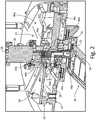
- FIG. 1 is a perspective view of aircraft 10.
- Aircraft 10 includes fuselage 12, wings 14, and engines 16.
- Fuselage 12 includes angle of attack (AOA) vane 18.
- AOA vane 18 projects from fuselage 12 forward of wings 14.
- AOA vane 18 rotates to align with the prevailing airflow.
- AOA vane 18 is preferably located forward of wings 14. Locating AOA vane 18 forward of wings 14 minimizes the effects on AOA vane 18 of the airflow affected by fuselage 12, wings 14, or engines 16, thereby ensuring the accuracy of AOA vane 18. For example, as aircraft 10 ascends, AOA vane 18 aligns with the prevailing airflow and indicates a high angle of attack. As aircraft 10 approaches a cruise altitude AOA vane 18 continues to track with the prevailing airflow, and AOA vane 18 thus indicates a lower angle of attack as aircraft 10 levels off. Because AOA vane 18 projects from fuselage 12, AOA vane 18 is exposed to the elements and is particularly susceptible to lighting strikes.
- AOA vane 18 When lightning strikes AOA vane 18 the electrical current generated by the lightning strike travels through AOA vane 18 and seeks a low-impedance path to fuselage 12. While AOA vane 18 is described as measuring the angle of attack, it is understood that AOA vane 18 may be any angular sensing instrument, such as an AOA vane or a side slip angle vane.
- FIG. 2 is a cross-sectional view of AOA vane 18, mounting system 20, and electric isolator 22.
- AOA vane 18 includes vane body 24 and shaft 26.
- Mounting system 20 includes outboard mounting flange 28, inboard mounting flange 30, outboard bearing 32, and inboard bearing 34.
- Mounting system 20 further includes rotary position sensor 36 and damper 38.
- Outboard bearing 32 includes outer race 40a, inner race 42a, and ball 44a.
- Inboard bearing 34 outer race 40b, inner race 42b, and ball 44b.
- Electric isolator 22 may include dielectric barrier 46a, dielectric barrier 46b, dielectric barrier 46c, and dielectric barrier 46d.
- Mounting system 20 is attached to fuselage 12 (shown in FIG. 1 ) and supports AOA vane 18.
- Outboard mounting flange 28 is disposed outward of and secured to inboard mounting flange 30.
- Shaft 26 extends through outboard mounting flange 28 and inboard mounting flange 30 and communicates with rotary position sensor 36.
- Rotary position sensor 36 is inboard of shaft 26 and is configured to sense a rotational displacement of shaft 26.
- Damper 38 extends about shaft 26 and typically includes a viscous fluid, such as oil, that dampens the rotation of shaft 26, and thus AOA vane 18, to slow the response time of AOA vane 18 to changes in airflow direction. As such, damper 38 ensures a smooth rotation of AOA vane 18, thus providing a smooth reading of the angle of attack.
- the damping fluid in damper 38 absorbs oscillations experienced by shaft 26, such as those vibrations experienced due to turbulence, and prevents variations in the angle of attack readings due to unwanted vibrations in shaft 26.
- Outboard bearing 32 is disposed between outboard mounting flange 28 and shaft 26 and rotationally supports shaft 26 relative to outboard mounting flange 28.
- Outer race 40a is attached to outboard mounting flange 28 and inner race 42a is attached to shaft 26.
- Ball 44a is disposed between outer race 40a and inner race 42a and supports outer race 40a and inner race 42 such that inner race 42a rotates relative to outer race 40a.
- Inboard bearing 34 is disposed between inboard mounting flange 30 and shaft 26 and rotationally supports shaft 26 relative to inboard mounting flange 30.
- Outer race 40b is attached to inboard mounting flange 30 and inner race 42b is attached to shaft 26.
- Ball 44b is disposed between outer race 40b and inner race 42b and supports outer race 40b and inner race 42b such that inner race 42b is free to rotate relative to outer race 40b.
- Mounting system 20 is attached to fuselage 12 (shown in FIG. 1 ).
- AOA vane 18 is rotatably supported by mounting system 20 with vane body 24 disposed outboard of fuselage 12 and shaft 26 supported by mounting system 20.
- Outboard mounting flange 28 is typically mounted on an exterior of fuselage 12 and inboard mounting flange 30 is mounted opposite of and attached to outboard mounting flange 28. In this way, outboard mounting flange 28 and inboard mounting flange 30 are attached to fuselage 12 to secure mounting system 20 and AOA vane 18 to fuselage 12.
- Vane body 24 aligning with the prevailing airflow causes shaft 26 to rotate, and rotary position sensor senses the rotational movement of shaft 26.
- Rotary position sensor 36 senses the rotational displacement of shaft 26 and communicates that information to other systems on aircraft 10 (shown in FIG. 1 ). The rotational displacement of shaft 26 and other information regarding the trajectory of aircraft 10 is used by the other systems onboard aircraft 10 to calculate the angle of attack, side slip angle, and the true direction of aircraft 10 travel, among other relevant information.
- Vane body 24 and outboard mounting flange 28 are disposed outboard of fuselage 12, and as such, vane body 24 and outboard mounting flange 28 are exposed and can attract lightning strikes.
- vane body 24 or outboard mounting flange 28 the electrical current seeks the path of least resistance to the metallic aircraft skin, which path of least resistance is typically through outboard bearing 32, inboard bearing 34, or both.
- the voltage generated by the lighting strike builds on inner race 42a or outer race 40a until the voltage exceeds an insulation level of an oil film layer within outboard bearing 32.
- EDM electrical discharge machining
- Electric isolator 22 prevents the electrical current associated with a lightning strike, which may exceed 130 kilovolts, from arcing across either outboard bearing 32; thereby damaging outer race 40a, inner race 42a, or ball 44a; or inboard bearing 34; thereby damaging outer race 40b, inner race 42b, or ball 44b.
- Dielectric barrier 46a may be formed from the components of outboard bearing 32 or inboard bearing 34. As such, dielectric barrier 46a may take the form of a hybrid bearing or a fully non-conducting bearing.
- ball 44a disposed between outer race 40a and inner race 42a may be comprised of a material forming dielectric barrier 46a. Where ball 44a is formed of the material, preferably a ceramic, forming dielectric barrier 46a, ball 44a forms a non-conducting barrier preventing electrical current from arcing between outer race 40a and inner race 42a.
- Dielectric barrier 46a may further include a ceramic outer race 40a and a ceramic inner race 42a, and in this way, outboard bearing 32 is a fully non-conducting bearing.
- dielectric barrier 46a be a ceramic ball 44a, a ceramic outer race 40a, a ceramic inner race 42a, or a combination thereof, electric currents are not conducted through outboard bearing 32, and outboard bearing 32 is thus protected from the high voltage of a lightning strike. While dielectric barrier 46a has been described in relation to outboard bearing 32, it is understood that dielectric barrier 46a applies equally to inboard bearing 34 such that one or more of ball 44b, outer race 40b, and inner race 42b may be formed of a non-conducting material, such as ceramic, to form dielectric barrier 46a.
- Hybrid bearings where ball 44a forms dielectric barrier 46a while outer race 40a and inner race 42a remain conducting
- all-dielectric bearings where ball 44a, outer race 40a, and inner race 42a form dielectric barrier 46a
- Hybrid bearings provide a higher load rating than all-metal counterparts, thereby increasing the durability and lifespan of the bearings.
- hybrid bearings and all-dielectric bearings prevent all electrical currents from passing through the bearing over the expected range of lightning strike voltage.
- hybrid and all-dielectric bearings both increase the lifespan and utility of outboard bearing 32 and inboard bearing 34, and consequently of AOA vane 18, and prevent outboard bearing 32 and inboard bearing 34 from being damaged by any electrical signal, whether from a lightning strike or from induced electrical currents, such as those created by variable frequency generators, for example.
- dielectric barrier 46b prevents the electrical current associated with a lightning strike from arcing across either outboard bearing 32 or inboard bearing 34.
- Dielectric barrier 46b forms a shaft-side non-conducting barrier.
- shaft 26 is constructed from a monolithic, dielectric material.
- shaft 26 may be formed from a ceramic, an engineered plastic, or a non-conductive composite material. Having a monolithic, non-conductive shaft 26 prevents an electrical path from forming through shaft 26 and to either outboard bearing 32 or inboard bearing 34. In this way, dielectric barrier 46b thereby prevents the electric current from flowing through and damaging outboard bearing 32 and inboard bearing 34.
- Dielectric barrier 46c similarly prevents an electrical current associated with a lightning strike from arcing between and damaging inner race 42a and outer race 40a.
- Dielectric barrier 46c forms an outboard mounting flange-side non-conducting barrier about outer race 40a.
- outboard mounting flange 28 is formed from a monolithic, dielectric material.
- outboard mounting flange 28 is preferably comprised of a ceramic, an engineered plastic, or a non-conductive composite material.
- Dielectric barrier 46c electrically isolates outer race 40a to prevent an electric current from flowing through outer race 40a.
- outboard bearing 32 is electrically isolated such that no electric current can flow through outboard bearing 32 between inner race 42a and outer race 40a.
- dielectric barrier 46c prevents outboard bearing 32 from sustaining EDM damage due to lightning strikes.
- dielectric barrier 46d electrically isolates outer race 40b and prevents an electrical current associated with a lightning strike from arcing between and damaging inner race 42b and outer race 40b.
- Dielectric barrier 46d forms an inboard mounting flange-side non-conducting barrier about outer race 40b.
- inboard mounting flange 30 preferably comprises a ceramic, an engineered plastic, or a non-conductive composite material.
- inboard mounting flange 30 forms dielectric barrier 46d
- inboard mounting flange 30 electrically isolates outer race 40b, thereby preventing an electric current from flowing through outer race 40b.
- Inboard bearing 34 is thus electrically isolated such that an electric current cannot flow through inboard bearing 34 between inner race 42b and outer race 40b.
- dielectric barrier 46d prevents inboard bearing 34 from sustaining EDM damage caused by lightning strikes.
- electric isolator 22 is described as including dielectric barrier 46a, dielectric barrier 46b, dielectric barrier 46c, and dielectric barrier 46d, it is understood that electric isolator 22 may include as few or as many of dielectric barriers 46a-d as desired.
- dielectric barrier 46a prevents an electric current from arcing between outer race 40a and inner race 42a by having one or more of ball 44a, outer race 40a, and inner race 42a consist of a ceramic material.
- dielectric barrier 46a provides sufficient electrical protection to outboard bearing 32 and inboard bearing 34 to prevent outboard bearing 32 and inboard bearing 34 from sustaining lightning strike damage.
- Dielectric barrier 46a is thus sufficiently robust to protect outboard bearing 32 and inboard bearing 34 and electric isolator may thus include dielectric barrier 46a alone.
- dielectric barrier 46b, dielectric barrier 46c, and dielectric barrier 46d provide sufficient electrical protection to outboard bearing 32 and inboard bearing 34 to prevent outboard bearing 32 and inboard bearing 34 from sustaining lightning strike damage. Therefore, electric isolator 22 may include any one or more of dielectric barrier 46a, dielectric barrier 46b, dielectric barrier 46c, and dielectric barrier 46d.
- Electric isolator 22 provides significant advantages. Electric isolator 22 provides increased strength and durability to mounting system 20 and AOA vane 18 by including monolithic, non-conducting dielectric barriers 46b, 46c, and 46d.
- the monolithic, non-conducting dielectric barriers 46b, 46c, and 46d provide greater structural integrity than metallic alloys, and the monolithic, non-conducting materials also offer greater thermal protection than metallic alloys, thereby reducing the need to heat various components of mounting system 20 and AOA vane 18, such as rotary position sensor 36 and other electronic components.
- various combinations of dielectric barriers 46a, 46b, 46c, and 46d provide robust electrical protection.
- dielectric barrier 46a and dielectric barrier 46b protects not only outboard bearing 32 and inboard bearing 34 from induced voltages, but also protects rotary position sensor 36, as well as other electronics, because induced voltages cannot pass through shaft 26 due to dielectric barrier 46b.
- FIG. 3 is a cross-sectional view of AOA vane 18, mounting system 20, and electric isolator 22'.
- AOA vane 18 includes vane body 24, shaft 26'.
- Mounting system 20 includes outboard mounting flange 28, inboard mounting flange 30, outboard bearing 32, and inboard bearing 34.
- Outboard bearing 32 includes outer race 40a, inner race 42a, and ball 44a.
- Inboard bearing 34 outer race 40b, inner race 42b, and ball 44b.
- Shaft 26' includes annular notch 48a and annular notch 48b.
- Electric isolator 22' includes inner dielectric sleeve 50a and inner dielectric sleeve 50b.
- Mounting system 20 is attached to fuselage 12 (shown in FIG. 1 ) and supports AOA vane 18.
- Outboard mounting flange 28 is disposed on an outward side of fuselage 12 and inboard mounting flange 30 is disposed on an inboard side of fuselage 12.
- Outboard mounting flange 28 is attached to inboard mounting flange 30 to secure mounting system 20 to fuselage 12.
- Shaft 26' extends through outboard mounting flange 28 and inboard mounting flange 30.
- Annular notch 48a extends into shaft 26' adjacent outboard bearing 32
- annular notch 48b extends into shaft 26' adjacent inboard bearing 34.
- Outboard bearing 32 is disposed between outboard mounting flange 28 and shaft 26' and rotatably supports shaft 26 relative to outboard mounting flange 28.
- Outer race 40a is disposed on outboard mounting flange 28 and inner race 42a is disposed on shaft 26' about annular notch 48a.
- Inner dielectric sleeve 50a is disposed within annular notch 48a between inner race 42a and shaft 26' such that inner race 42a abuts inner dielectric sleeve 50a.
- Inner dielectric sleeve 50a prevents inner race 42a from contacting shaft 26'.
- Ball 44a is disposed between outer race 40a and inner race 42a and rotatably supports outer race 40a and inner race 42.
- Inboard bearing 34 is disposed between inboard mounting flange 30 and shaft 26' and rotatably supports shaft 26' relative to inboard mounting flange 30.
- Outer race 40b is disposed on inboard mounting flange 30 and inner race 42b is disposed on shaft 26' about annular notch 48b.
- Inner dielectric sleeve 50b is disposed within annular notch 48b between inner race 42b and shaft 26' such that inner race 42b contacts inner dielectric sleeve 50b, but inner dielectric sleeve 50b prevents inner race 42b from contacting shaft 26'.
- Ball 44b is disposed between outer race 40b and inner race 42b and rotatably supports outer race 40b and inner race 42b such that inner race 42b is free to rotate relative to outer race 40b.
- Inner dielectric sleeve 50a and inner dielectric sleeve 50b are formed from a non-conductive material such that an electric current cannot pass through either inner dielectric sleeve 50a or inner dielectric sleeve 50b.
- Vane body 24 and outboard mounting flange 28 are disposed outboard of fuselage 12, and as such, vane body 24 and outboard mounting flange 28 are exposed and can attract lightning.
- the electrical current seeks the path of least resistance to the metallic aircraft skin, which path of least resistance is typically through outboard bearing 32, inboard bearing 34, or both.
- the electrical current travels through outboard bearing 32, the electrical current arcs between outer race 40a and inner race 42a and can create EDM pits in outer race 40a and inner race 42a.
- the electrical current can arc across inboard bearing 34 between outer race 40b and inner race 42b and create EDM pits in outer race 40b and inner race 42b.
- Electric isolator 22' prevents the electrical current associated with a lightning strike, which may exceed 130 kilovolts, from arcing across either outboard bearing 32 or inboard bearing 34.
- Inner dielectric sleeve 50a provides a first dielectric barrier about shaft 26 between shaft 26' and inner race 42a such that no electric current can travel between inner race 42a and shaft 26'.
- inner dielectric sleeve 50a prevents the electric current from passing through outboard bearing 32 because the electric current cannot pass through inner dielectric sleeve 50a between inner race 42a and shaft 26'.
- Inner dielectric sleeve 50a thus electrically isolates outboard bearing 32 such that the electric current generated by a lightning strike cannot travel through outboard bearing 32, thereby preventing outboard bearing 32 from being damaged due to a lightning strike.
- inner dielectric sleeve 50b provides a second dielectric barrier about shaft 26, between shaft 26' and inner race 42b such that no electric current can travel between inner race 42b and shaft 26'.
- inner dielectric sleeve 50b prevents the electric current from passing through outboard bearing 32 because the electric current cannot pass through inner dielectric sleeve 50b between inner race 42b and shaft 26'.
- Inner dielectric sleeve 50b thus electrically isolates inboard bearing 34 such that the electric current generated by a lightning strike cannot travel through inboard bearing 34, thereby preventing inboard bearing 34 from being damaged due to a lightning strike.
- Inner dielectric sleeve 50a and inner dielectric sleeve 50b protect outboard bearing 32 and inboard bearing 34 from induced voltages caused by lightning strikes, which can reach upwards of 130 kilovolts. Unlike a ceramic coating on inner race 42a or inner race 42b, which may protect for voltages up to about 3 kilovolts, inner dielectric sleeve 50a and inner dielectric sleeve 50b provide robust electrical protection.
- FIG. 4 is a cross-sectional view of AOA vane 18, mounting system 20, and electric isolator 22".
- AOA vane 18 includes vane body 24, shaft 26.
- Mounting system 20 includes outboard mounting flange 28', inboard mounting flange 30', outboard bearing 32, and inboard bearing 34.
- Outboard bearing 32 includes outer race 40a, inner race 42a, and ball 44a.
- Inboard bearing 34 outer race 40b, inner race 42b, and ball 44b.
- Outboard mounting flange 28' includes flange notch 52a
- inboard mounting flange 30' includes flange notch 52b.
- Electric isolator 22" includes outer dielectric sleeve 54a and outer dielectric sleeve 54b.
- Mounting system 20 is attached to fuselage 12 (shown in FIG. 1 ) and supports AOA vane 18.
- Outboard mounting flange 28' is disposed on an outward side of fuselage 12 and inboard mounting flange 30' is disposed on an inboard side of fuselage 12.
- Outboard mounting flange 28' is attached to inboard mounting flange 30' to secure mounting system 20 to fuselage 12.
- Shaft 26 extends through outboard mounting flange 28' and inboard mounting flange 30'.
- Flange notch 52a extends annularly about an inner wall of outboard mounting flange 28', and outer dielectric sleeve 54a is disposed within flange notch 52a.
- Flange notch 52b extends annularly about an inner wall of inboard mounting flange 30', and outer dielectric sleeve 54b is disposed within flange notch 52b.
- Outer dielectric sleeve 54a is made from a non-conducting material, such as a ceramic, an engineered plastic, or a composite material.
- outer dielectric sleeve 54b is made from a non-conducting material, such as a ceramic, an engineered plastic, or a composite material.
- Outboard bearing 32 is disposed between outboard mounting flange 28' and shaft 26 and rotationally supports shaft 26 relative to outboard mounting flange 28'.
- Outer race 40a is disposed on outer dielectric sleeve 54a, which is connected to outboard mounting flange 28' and disposed within flange notch 52a.
- Inner race 42a is attached to shaft 26, and ball 44a is disposed between outer race 40a and inner race 42a.
- Inboard bearing 34 is disposed between inboard mounting flange 30' and shaft 26 and rotationally supports shaft 26 relative to inboard mounting flange 30'.
- Outer race 40b is disposed on outer dielectric sleeve 54b, which is connected to inboard mounting flange 30' and disposed within flange notch 52b.
- Inner race 42b is attached to shaft 26, and ball 44b is disposed between outer race 40b and inner race 42b.
- vane body 24 projects outboard of fuselage 12, and outboard mounting flange 28' similarly is exposed to the environment outboard of fuselage 12. As such, vane body 24 and outboard mounting flange 28' are exposed and can attract lightning strikes.
- vane body 24 or outboard mounting flange 28' the electric current attempts to travel to the metallic skin of fuselage 12.
- the electrical current travels down vane body 24 and along shaft 26. From shaft 26 the electrical current generally travels through outboard bearing 32 and inboard bearing 34 because outboard bearing 32 and inboard bearing 34 present the path of least resistance to the electrical current.
- outboard mounting flange 28' when lightning strikes outboard mounting flange 28', the path of least electrical resistance for the electrical current to travel through is through outboard bearing 32, inboard bearing 34, or both. Whether the lightning strikes vane body 24 or outboard mounting flange 28' the electrical current can arc across outboard bearing 32, between outer race 40a and inner race 42a, thereby creating EDM pits in outer race 40a and inner race 42a. The electrical current can also arc across inboard bearing 34, between outer race 40b and inner race 42b, and create EDM pits in outer race 40b and inner race 42b. The EDM pits in both outboard bearing 32 can cause friction and can lead to premature bearing of AOA vane failure.
- Electric isolator 22" prevents an electrical current associated with a lightning strike, which may exceed 130 kilovolts, from passing through either outboard bearing 32 or inboard bearing 34.
- Outer dielectric sleeve 54a provides a dielectric barrier between outer race 40a and outboard mounting flange 28'.
- Outer dielectric sleeve 54a electrically isolates outboard bearing 32 to prevent any voltage, from stray electrical currents to those generated by a lightning strike, from passing through and damaging outboard bearing 32 between inner race 42a and outer race 40a. In this way, outer dielectric sleeve 54a prevents electrical current from flowing through outboard bearing 32, as the electric current cannot pass through outer dielectric sleeve 54a.
- Outer dielectric sleeve 54a thus breaks any electrical pathway through outboard bearing 32, thereby protecting outboard bearing 32 from electrical currents.
- outer dielectric sleeve 54b provides a dielectric barrier between outer race 40b and inboard mounting flange 30'.
- Outer dielectric sleeve 54 is disposed between outer race 40b and inboard mounting flange 30' such that outer dielectric sleeve 54 contacts outer race 40 while preventing inboard mounting flange 30' and outer race 40b from coming into contact.
- Outer dielectric sleeve 54b electrically isolates inboard bearing 34 such that any voltage, from stray electrical currents to those generated by a lightning strike, is prevented from passing through and damaging inboard bearing 34.
- outer dielectric sleeve 54b prevents electrical current from flowing through inboard bearing 34 as the electrical current cannot pass through outer dielectric sleeve 54b. Outer dielectric sleeve 54b thus breaks any electrical pathway through inboard bearing 34, thereby protecting inboard bearing 34 from electrical currents.
- Electric isolator 22" provides significant advantages.
- Outer dielectric sleeve 54a and outer dielectric sleeve 54b protect outboard bearing 32 and inboard bearing 34 from induced voltages caused by lightning strikes, which can reach upwards of 130 kilovolts.
- outer dielectric sleeve 54a and outer dielectric sleeve 54b provide robust electrical protection.
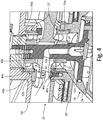
- FIG. 5 is a cross-sectional view of AOA vane 18, mounting system 20, and electric isolator 22'''.
- AOA vane 18 includes vane body 24, shaft 26.
- Mounting system 20 includes outboard mounting flange 28, inboard mounting flange 30, outboard bearing 32, and inboard bearing 34.
- Mounting system 20 further includes rotary position sensor 36 and damper 38.
- Outboard bearing 32 includes outer race 40a, inner race 42a, and ball 44a.
- Inboard bearing 34 outer race 40b, inner race 42b, and ball 44b.
- Mounting system 20 is attached to fuselage 12 (shown in FIG. 1 ) and supports AOA vane 18.
- Outboard mounting flange 28 is disposed outward of and secured to inboard mounting flange 30.
- Shaft 26 extends through outboard mounting flange 28 and inboard mounting flange 30 and communicates with rotary position sensor 36.
- Rotary position sensor 36 is inboard of shaft 26 and is configured to sense a rotational displacement of shaft 26.
- Damper 38 extends about shaft 26 and typically includes a viscous fluid, such as oil, that dampens the rotation of shaft 26 and any vibrations experienced by shaft 26.
- Outboard bearing 32 is attached to both outboard mounting flange 28 and shaft 26 and rotationally supports shaft 26 relative to outboard mounting flange 28.
- Outer race 40a is attached to outboard mounting flange 28 and inner race 42a is attached to shaft 26.
- Ball 44a is disposed between outer race 40a and inner race 42a and supports outer race 40a and inner race 42a such that inner race 42a rotates relative to outer race 40a.
- Inboard bearing 34 is attached to both inboard mounting flange 30 and shaft 26 and rotationally supports shaft 26 relative to inboard mounting flange 30.
- Outer race 40b is attached to inboard mounting flange 30 and inner race 42b is attached to shaft 26.
- Ball 44b is disposed between outer race 40b and inner race 42b and supports outer race 40b and inner race 42b such that inner race 42b is free to rotate relative to outer race 40b.
- Electric isolator 22'" is connected to shaft 26 and is electrically connected to outboard mounting flange 28.
- Electric isolator 22'" is a grounding device, such as a grounding ring or a grounding brush, connected to shaft 26.
- Electric isolator 22''' provides an alternate low-impedance path from shaft 26 to outboard mounting flange 28, and thus to the skin of fuselage 12 (shown in FIG. 1 ).
- Electric isolator 22''' thus reduces or eliminates voltage on shaft 26, and thus on outboard bearing 32 and inboard bearing 34, by preventing voltage from building on shaft 26. As such, the electrical current generated by a lightning strike is routed away from outboard bearing 32 and inboard bearing 34, thereby protecting both outboard bearing 32 and inboard bearing 34.
- An angle of attack vane mounting system includes a mounting flange secured to an aircraft; a shaft extending through the mounting flange; a bearing disposed between the mounting flange and the shaft, wherein the bearing includes an inner race attached to the shaft and an outer race attached to the mounting flange; and an electric isolator disposed adjacent one of the inner race and the outer race and electrically isolating the bearing such that an electric current is prevented from passing between the inner race and the outer race.
- the angle of attack vane mounting system of the preceding paragraph can optionally include, additionally and/or alternatively, any one or more of the following features, configurations and/or additional components:
- the electric isolator comprises a sleeve disposed between the shaft and the inner race.
- the electric isolator comprises a sleeve disposed between the mounting flange and the outer race.
- the electric isolator comprises a ceramic rolling element disposed between the inner race and the outer race.
- the shaft comprises a dielectric material.
- An angle of attack vane for an aircraft an outboard mounting flange; an inboard mounting flange disposed adjacent the outboard mounting flange; a shaft extending through the outboard mounting flange and the inboard mounting flange; an inboard bearing rotatably supporting the shaft and disposed between the shaft and the inboard mounting flange; an inboard electric isolator configured to prevent an electric current from traveling through the inboard bearing; an outboard bearing rotatably supporting the shaft and disposed between the outboard mounting flange and the shaft; an outboard electric isolator configured to prevent an electric current from traveling through the outboard bearing; and a vane extending from the shaft outboard of the outboard mounting flange.
- the angle of attack vane of the preceding paragraph can optionally include, additionally and/or alternatively, any one or more of the following features, configurations and/or additional components:
- the inboard electric isolator includes a ceramic inboard rolling ball disposed between an inboard outer race of the inboard bearing and an inboard outer race of the bearing, wherein the ceramic inboard rolling ball is configured to prevent an electric current from passing between the inboard inner race and the inboard outer race.
- the inboard inner race is a dielectric material and the inboard outer race is the dielectric material.
- the dielectric material comprises one of a ceramic, an engineered plastic, or a composite material.
- a grounding brush is disposed about the shaft and configured to ground the shaft to a fuselage of the aircraft.
- the inboard electric isolator includes a first sleeve disposed about the shaft and adjacent an inboard inner race of the inboard bearing, and the outboard electric isolator comprises a second sleeve disposed about the shaft and adjacent an outboard inner race of the outboard bearing.
- the inboard electric isolator comprises a first sleeve disposed between the inboard mounting flange and an inboard inner race of the inboard bearing
- the outboard electric isolator comprises a second sleeve disposed between the outboard mounting flange and an outboard inner race of the outboard bearing.
- the outboard mounting flange comprises a dielectric material.
- the shaft comprises a dielectric material.
- the inboard mounting flange comprises a dielectric material.
- a method of preventing lightning strike damage to a bearing of an angle of attack vane includes mounting an angle of attack vane shaft on a bearing disposed between the angle of attack vane shaft and a mounting flange, and electrically isolating the bearing such that an electrical current cannot pass between an inner race of the bearing and an outer race of the bearing.
- the method of the preceding paragraph can optionally include, additionally and/or alternatively, any one or more of the following features, configurations and/or additional components: Mounting a ceramic rolling element between the inner race and the outer race.
Landscapes
- Engineering & Computer Science (AREA)
- General Engineering & Computer Science (AREA)
- Aviation & Aerospace Engineering (AREA)
- Mechanical Engineering (AREA)
- Ceramic Engineering (AREA)
- Physics & Mathematics (AREA)
- General Physics & Mathematics (AREA)
- Motor Or Generator Frames (AREA)
- Rolling Contact Bearings (AREA)
- Elimination Of Static Electricity (AREA)
- Wind Motors (AREA)
Claims (15)
- Système de montage (20) d'aube d'angle d'attaque (18) comprenant :une première bride de montage (28 ; 28') configurée pour être assujettie à un aéronef (10) ;un arbre (26 ; 26') s'étendant à travers la première bride de montage (28 ; 28') ;un premier palier (32) disposé entre la première bride de montage (28 ; 28') et l'arbre (26 ; 26'), dans lequel le premier palier (32) comprend :un premier chemin de roulement interne (42a) fixé à l'arbre (26 ; 26') ; etune premier chemin de roulement externe (40a) fixé à la première bride de montage (28 ; 28') ; etun premier isolateur électrique (22 ; 22' ; 22" ; 22"') disposé adjacent à l'un du premier chemin de roulement interne (42a) et du premier chemin de roulement externe (40a) et isolant électriquement le palier (32) de façon à empêcher un courant électrique de passer entre le premier chemin de roulement interne (42a) et le premier chemin de roulement externe (40a).
- Système de montage d'aube d'angle d'attaque selon la revendication 1, comprenant en outre :une seconde bride de montage (30 ; 30') disposée adjacente à la première bride de montage (28 ; 28') ;un second palier (34) supportant en rotation l'arbre (26 ; 26') et disposé entre la seconde bride de montage (30 ; 30') et l'arbre (26 ; 26'), dans lequel le second palier (34) comprend :un second chemin de roulement interne (42b) fixé à l'arbre (26 ; 26') ; etun second chemin de roulement externe (40b) fixé à la seconde bride de montage (30 ; 30') ;un second isolateur électrique (22 ; 22' ; 22" ; 22''') configuré pour empêcher un courant électrique de circuler à travers le second palier (34).
- Système de montage d'aube d'angle d'attaque selon la revendication 1 ou 2, dans lequel le premier isolateur électrique (22 ; 22' ; 22" ; 22"') comprend :
une première boule roulante en céramique (44a) disposée entre le premier chemin de roulement externe (40a) du premier palier (32) et le premier chemin de roulement interne (42a) du premier palier (32), dans lequel la première boule roulante en céramique (44a) est configurée pour empêcher un courant électrique de passer entre le premier chemin de roulement interne (42a) et le premier chemin de roulement externe (40a). - Système de montage d'aube d'angle d'attaque selon une quelconque revendication précédente, dans lequel le premier chemin de roulement interne (42a) est un matériau diélectrique et le premier chemin de roulement externe (40a) est le matériau diélectrique.
- Système de montage d'aube d'angle d'attaque selon la revendication 4, dans lequel le matériau diélectrique comprend l'un d'une céramique, d'un plastique technique ou d'un matériau composite.
- Système de montage d'aube d'angle d'attaque selon une quelconque revendication précédente, dans lequel une douille de mise à la terre (22"') est disposée autour de l'arbre (26) et configurée pour mettre à la terre l'arbre (26) par rapport à un fuselage (12) de l'aéronef (10).
- Système de montage d'aube d'angle d'attaque selon l'une quelconque des revendications 2 à 6, et dans lequel :le premier isolateur électrique (22') comprend un premier manchon (50a) disposé autour de l'arbre (26') et adjacent au premier chemin de roulement interne (42a) du premier palier (32) ; etle second isolateur électrique (22') comprend un second manchon (50b) disposé autour de l'arbre (26') et adjacent au second chemin de roulement interne (42b) du second palier (34).
- Système de montage d'aube d'angle d'attaque selon l'une quelconque des revendications 2 à 6, et dans lequel :le premier isolateur électrique (22") comprend un premier manchon (54a) disposé entre la première bride de montage (28') et le premier chemin de roulement externe (40a) du premier palier (32) ; etle second isolateur électrique (22") comprend un second manchon (54b) disposé entre la seconde bride de montage (30') et le second chemin de roulement externe (40b) du second palier (34).
- Système de montage d'aube d'angle d'attaque selon une quelconque revendication précédente, dans lequel la première bride de montage (28 ; 28') comprend un, le ou un autre matériau diélectrique.
- Système de montage d'aube d'angle d'attaque selon une quelconque revendication précédente, dans lequel l'arbre (26 ; 26') comprend un, le ou un autre matériau diélectrique.
- Procédé anti-endommagement par foudroiement d'un palier (32, 34) d'une aube d'angle d'attaque (18), le procédé comprenant :le montage d'un arbre d'aube d'angle d'attaque (26 ; 26') sur un palier (32, 34) disposé entre l'arbre d'aube d'angle d'attaque (26 ; 26') et une bride de montage (28, 30 ; 28', 30') ; etl'isolation électrique du palier (32, 34) de sorte qu'un courant électrique ne puisse pas passer entre un chemin de roulement interne (42a, b) du palier (32, 34) et un chemin de roulement externe (40a, b) du palier (32, 34).
- Procédé selon la revendication 11, dans lequel l'étape d'isolation électrique du palier (32, 34) de sorte qu'un courant électrique ne puisse pas passer entre un chemin de roulement interne (42a, b) du palier (32, 34) et un chemin de roulement externe (40a, b) du palier (32, 34) comprend :
le montage d'un élément roulant en céramique (44a, b) entre le chemin de roulement interne (42a, b) et le chemin de roulement externe (40a, b). - Procédé selon la revendication 11 ou 12, dans lequel l'étape d'isolation électrique du palier (32, 34) de sorte qu'un courant électrique ne puisse pas passer entre un chemin de roulement interne (42a, b) du palier (32, 34) et un chemin de roulement externe (40a, b) du palier (32, 34) comprend :
le montage d'un élément de mise à la terre (22"') sur l'arbre (26) adjacent au palier (32), de sorte que l'arbre (26) soit mis à la terre par rapport à un aéronef (10). - Procédé selon l'une quelconque des revendications 11 à 13, dans lequel l'étape d'isolation électrique du palier (32, 34) de sorte qu'un courant électrique ne puisse pas passer entre un chemin de roulement interne (42a, b) du palier (32, 34) et un chemin de roulement externe (40a, b) du palier (32, 34) comprend :
le montage d'un manchon diélectrique (50a, b) sur l'arbre (26') entre l'arbre (26') et le chemin de roulement interne (42a, b). - Procédé selon l'une quelconque des revendications 11 à 14, dans lequel l'étape d'isolation électrique du palier (32, 34) de sorte qu'un courant électrique ne puisse pas passer entre un chemin de roulement interne (42a, b) du palier (32, 34) et un chemin de roulement externe (40a, b) du palier (32, 34) comprend :
le montage d'un ou d'un autre manchon diélectrique (54a, b) sur une bride de montage (28', 30') adjacent au chemin de roulement externe (40a, b) du palier (32,34).
Applications Claiming Priority (1)
| Application Number | Priority Date | Filing Date | Title |
|---|---|---|---|
| US15/267,309 US10457412B2 (en) | 2016-09-16 | 2016-09-16 | Electrical isolation of angle of attack vane bearings |
Publications (2)
| Publication Number | Publication Date |
|---|---|
| EP3296580A1 EP3296580A1 (fr) | 2018-03-21 |
| EP3296580B1 true EP3296580B1 (fr) | 2019-04-24 |
Family
ID=59914316
Family Applications (1)
| Application Number | Title | Priority Date | Filing Date |
|---|---|---|---|
| EP17191546.5A Active EP3296580B1 (fr) | 2016-09-16 | 2017-09-18 | Isolation électrique d'angle d'attaque de paliers d'aubes |
Country Status (3)
| Country | Link |
|---|---|
| US (1) | US10457412B2 (fr) |
| EP (1) | EP3296580B1 (fr) |
| CA (1) | CA2974583C (fr) |
Families Citing this family (13)
| Publication number | Priority date | Publication date | Assignee | Title |
|---|---|---|---|---|
| US10393766B2 (en) | 2017-08-17 | 2019-08-27 | Rosemount Aerospace Inc. | Water management system for angle of attack sensors |
| US11181545B2 (en) | 2017-08-17 | 2021-11-23 | Rosemount Aerospace Inc. | Angle of attack sensor with thermal enhancement |
| US10730637B2 (en) * | 2017-09-29 | 2020-08-04 | Rosemount Aerospace Inc. | Integral vane base angle of attack sensor |
| US11162970B2 (en) | 2019-06-17 | 2021-11-02 | Rosemount Aerospace Inc. | Angle of attack sensor |
| US11237031B2 (en) | 2019-08-20 | 2022-02-01 | Rosemount Aerospace Inc. | Additively manufactured heaters for air data probes having a heater layer and a dielectric layer on the air data probe body |
| US11649057B2 (en) | 2019-12-13 | 2023-05-16 | Rosemount Aerospace Inc. | Static plate heating arrangement |
| US11237183B2 (en) * | 2019-12-13 | 2022-02-01 | Rosemount Aerospace Inc. | Ceramic probe head for an air data probe with and embedded heater |
| US12360134B2 (en) | 2020-02-25 | 2025-07-15 | Rosemount Aerospace Inc. | Angle of attack sensor with sloped faceplate |
| US11802888B2 (en) * | 2020-09-21 | 2023-10-31 | Rosemount Aerospace Inc. | Damage detection for rotary angle measurement sensors |
| US11565463B2 (en) | 2020-10-20 | 2023-01-31 | Rosemount Aerospace Inc. | Additively manufactured heater |
| CN113090440B (zh) * | 2021-04-13 | 2023-03-17 | 哈动国家水力发电设备工程技术研究中心有限公司 | 一种检验水泵水轮机转轮破损的方法 |
| US11662235B2 (en) | 2021-10-01 | 2023-05-30 | Rosemount Aerospace Inc. | Air data probe with enhanced conduction integrated heater bore and features |
| US11624637B1 (en) | 2021-10-01 | 2023-04-11 | Rosemount Aerospace Inc | Air data probe with integrated heater bore and features |
Family Cites Families (18)
| Publication number | Priority date | Publication date | Assignee | Title |
|---|---|---|---|---|
| US3548654A (en) * | 1969-02-10 | 1970-12-22 | Howard W Cole Jr | True air speed meter with relative wind direction |
| GB1272850A (en) * | 1969-12-15 | 1972-05-03 | Ferranti Ltd | Improvements relating to airflow direction indicators |
| US3882721A (en) * | 1973-11-16 | 1975-05-13 | Rosemount Inc | Vane type airflow sensor |
| US4230290A (en) * | 1978-05-01 | 1980-10-28 | Townsend Engineering Company | Airplane angle of attack and direction of flight indicator |
| JPH03103615A (ja) * | 1989-09-12 | 1991-04-30 | Railway Technical Res Inst | 電気絶縁軸受 |
| US5438865A (en) * | 1993-12-16 | 1995-08-08 | Safe Flight Instrument Corporation | Angle of attack sensor |
| US5544526A (en) * | 1994-06-30 | 1996-08-13 | Avionics Specialties, Inc. | Combined aircraft angle of attack and dynamic/static pressure sensor assembly |
| US5735615A (en) * | 1996-10-04 | 1998-04-07 | Reliance Electric Industrial Company | Insulation arrangement for electrical machine shaft bearing |
| JP2001336538A (ja) | 2000-05-26 | 2001-12-07 | Nsk Ltd | 転がり軸受とその製造方法 |
| US6612166B2 (en) * | 2001-12-13 | 2003-09-02 | Rosemount Aerospace Inc. | Variable viscosity damper for vane type angle of attack sensor |
| US8393791B2 (en) * | 2009-08-17 | 2013-03-12 | The Boeing Company | Bearing side face electrical isolation |
| FR3002320B1 (fr) * | 2013-02-20 | 2016-05-20 | Airbus Operations Sas | Sonde de mesure angulaire a bord d'un aeronef et aeronef mettant en oeuvre au moins une telle sonde |
| CA2943587C (fr) * | 2014-03-28 | 2022-08-02 | Bombardier Inc. | Protection contre la foudre pour avionique d'antenne d'avion |
| US9884685B2 (en) * | 2014-05-28 | 2018-02-06 | The Boeing Company | External case heater for an angle of attack sensor |
| US9482283B2 (en) * | 2014-06-05 | 2016-11-01 | Siemens Aktiengesellschaft | Bearing insulation |
| US9702783B2 (en) * | 2014-08-01 | 2017-07-11 | Rosemount Aerospace Inc. | Air data probe with fluid intrusion sensor |
| US9482269B2 (en) * | 2014-09-17 | 2016-11-01 | Roller Bearing Company Of America, Inc. | System for isolating electrical current in a bearing for use in an aircraft structure |
| US10457411B2 (en) * | 2016-06-17 | 2019-10-29 | Goodrich Corporation | Lightning strike dispersion for composite aircraft structures |
-
2016
- 2016-09-16 US US15/267,309 patent/US10457412B2/en active Active
-
2017
- 2017-07-25 CA CA2974583A patent/CA2974583C/fr active Active
- 2017-09-18 EP EP17191546.5A patent/EP3296580B1/fr active Active
Non-Patent Citations (1)
| Title |
|---|
| None * |
Also Published As
| Publication number | Publication date |
|---|---|
| EP3296580A1 (fr) | 2018-03-21 |
| US10457412B2 (en) | 2019-10-29 |
| CA2974583C (fr) | 2024-01-09 |
| US20180079525A1 (en) | 2018-03-22 |
| CA2974583A1 (fr) | 2018-03-16 |
| BR102017019114A2 (pt) | 2018-04-10 |
Similar Documents
| Publication | Publication Date | Title |
|---|---|---|
| EP3296580B1 (fr) | Isolation électrique d'angle d'attaque de paliers d'aubes | |
| EP2980589B1 (fr) | Sonde de données d'air avec détecteur d'intrusion de fluide | |
| SE507013C2 (sv) | Anordning för fasthållning av bladen till en flygplanspropeller | |
| EP3597532B1 (fr) | Agencement et procédé de rétroaction d'angle de pale d'hélice | |
| EP3401542A1 (fr) | Revêtements multicouches pour protéger les surfaces de la foudre | |
| CN110725720B (zh) | 推进器叶片角度反馈装置和方法 | |
| EP3006751B1 (fr) | Système pour isoler le courant électrique dans un palier destiné à être utilisé dans une structure d'avion | |
| US20130342189A1 (en) | Rotational device | |
| US11560923B2 (en) | Self-lubricated electrically conductive bushing | |
| US11802888B2 (en) | Damage detection for rotary angle measurement sensors | |
| JP2016147516A (ja) | バーストディスク装置および航空機 | |
| BR102017019114B1 (pt) | Sistema de montagem de pá de ângulo de ataque, e, método para evitar danos por relâmpagos a um mancal de uma pá de ângulo de ataque | |
| US8814587B2 (en) | Low impedance equipment interface | |
| CN104066984B (zh) | 用于风力涡轮机的轴承布置 | |
| EP2971610B1 (fr) | Enlèvement ou masquage sélectif de revêtement pour une piste de mise à la terre | |
| EP4060300A1 (fr) | Manchons de protection pour systèmes de détection d'incendie et de surchauffe pour applications d'aéronef | |
| US7411401B1 (en) | Systems and methods for reducing common-mode platform noise in electric-field sensors | |
| EP3874167B1 (fr) | Système de dissipation de charge électrique pour une pale d'éolienne, pale d'éolienne et méthode associée | |
| EP2774960B1 (fr) | Composant d'aéronef avec nanorevêtement électriquement conducteur | |
| JP2024038953A (ja) | 落雷抑制型風力発電設備、及び風力発電用風車 | |
| KR101745688B1 (ko) | 터빈 로터 변위 측정 기능이 포함된 저널 베어링 |
Legal Events
| Date | Code | Title | Description |
|---|---|---|---|
| PUAI | Public reference made under article 153(3) epc to a published international application that has entered the european phase |
Free format text: ORIGINAL CODE: 0009012 |
|
| STAA | Information on the status of an ep patent application or granted ep patent |
Free format text: STATUS: THE APPLICATION HAS BEEN PUBLISHED |
|
| AK | Designated contracting states |
Kind code of ref document: A1 Designated state(s): AL AT BE BG CH CY CZ DE DK EE ES FI FR GB GR HR HU IE IS IT LI LT LU LV MC MK MT NL NO PL PT RO RS SE SI SK SM TR |
|
| AX | Request for extension of the european patent |
Extension state: BA ME |
|
| STAA | Information on the status of an ep patent application or granted ep patent |
Free format text: STATUS: REQUEST FOR EXAMINATION WAS MADE |
|
| 17P | Request for examination filed |
Effective date: 20180917 |
|
| RBV | Designated contracting states (corrected) |
Designated state(s): AL AT BE BG CH CY CZ DE DK EE ES FI FR GB GR HR HU IE IS IT LI LT LU LV MC MK MT NL NO PL PT RO RS SE SI SK SM TR |
|
| GRAP | Despatch of communication of intention to grant a patent |
Free format text: ORIGINAL CODE: EPIDOSNIGR1 |
|
| STAA | Information on the status of an ep patent application or granted ep patent |
Free format text: STATUS: GRANT OF PATENT IS INTENDED |
|
| RIC1 | Information provided on ipc code assigned before grant |
Ipc: B64D 43/00 20060101ALI20181008BHEP Ipc: F16C 19/16 20060101ALN20181008BHEP Ipc: B64D 43/02 20060101ALI20181008BHEP Ipc: B64D 45/02 20060101ALI20181008BHEP Ipc: F16C 33/30 20060101ALI20181008BHEP Ipc: F16C 11/04 20060101AFI20181008BHEP |
|
| RIC1 | Information provided on ipc code assigned before grant |
Ipc: B64D 43/00 20060101ALI20181016BHEP Ipc: F16C 11/04 20060101AFI20181016BHEP Ipc: F16C 33/30 20060101ALI20181016BHEP Ipc: F16C 19/16 20060101ALN20181016BHEP Ipc: B64D 45/02 20060101ALI20181016BHEP Ipc: B64D 43/02 20060101ALI20181016BHEP |
|
| INTG | Intention to grant announced |
Effective date: 20181106 |
|
| GRAS | Grant fee paid |
Free format text: ORIGINAL CODE: EPIDOSNIGR3 |
|
| GRAA | (expected) grant |
Free format text: ORIGINAL CODE: 0009210 |
|
| STAA | Information on the status of an ep patent application or granted ep patent |
Free format text: STATUS: THE PATENT HAS BEEN GRANTED |
|
| AK | Designated contracting states |
Kind code of ref document: B1 Designated state(s): AL AT BE BG CH CY CZ DE DK EE ES FI FR GB GR HR HU IE IS IT LI LT LU LV MC MK MT NL NO PL PT RO RS SE SI SK SM TR |
|
| REG | Reference to a national code |
Ref country code: GB Ref legal event code: FG4D |
|
| REG | Reference to a national code |
Ref country code: CH Ref legal event code: EP |
|
| REG | Reference to a national code |
Ref country code: AT Ref legal event code: REF Ref document number: 1124490 Country of ref document: AT Kind code of ref document: T Effective date: 20190515 Ref country code: IE Ref legal event code: FG4D |
|
| REG | Reference to a national code |
Ref country code: DE Ref legal event code: R096 Ref document number: 602017003487 Country of ref document: DE |
|
| REG | Reference to a national code |
Ref country code: NL Ref legal event code: MP Effective date: 20190424 |
|
| REG | Reference to a national code |
Ref country code: LT Ref legal event code: MG4D |
|
| PG25 | Lapsed in a contracting state [announced via postgrant information from national office to epo] |
Ref country code: NL Free format text: LAPSE BECAUSE OF FAILURE TO SUBMIT A TRANSLATION OF THE DESCRIPTION OR TO PAY THE FEE WITHIN THE PRESCRIBED TIME-LIMIT Effective date: 20190424 |
|
| PG25 | Lapsed in a contracting state [announced via postgrant information from national office to epo] |
Ref country code: ES Free format text: LAPSE BECAUSE OF FAILURE TO SUBMIT A TRANSLATION OF THE DESCRIPTION OR TO PAY THE FEE WITHIN THE PRESCRIBED TIME-LIMIT Effective date: 20190424 Ref country code: LT Free format text: LAPSE BECAUSE OF FAILURE TO SUBMIT A TRANSLATION OF THE DESCRIPTION OR TO PAY THE FEE WITHIN THE PRESCRIBED TIME-LIMIT Effective date: 20190424 Ref country code: FI Free format text: LAPSE BECAUSE OF FAILURE TO SUBMIT A TRANSLATION OF THE DESCRIPTION OR TO PAY THE FEE WITHIN THE PRESCRIBED TIME-LIMIT Effective date: 20190424 Ref country code: HR Free format text: LAPSE BECAUSE OF FAILURE TO SUBMIT A TRANSLATION OF THE DESCRIPTION OR TO PAY THE FEE WITHIN THE PRESCRIBED TIME-LIMIT Effective date: 20190424 Ref country code: SE Free format text: LAPSE BECAUSE OF FAILURE TO SUBMIT A TRANSLATION OF THE DESCRIPTION OR TO PAY THE FEE WITHIN THE PRESCRIBED TIME-LIMIT Effective date: 20190424 Ref country code: AL Free format text: LAPSE BECAUSE OF FAILURE TO SUBMIT A TRANSLATION OF THE DESCRIPTION OR TO PAY THE FEE WITHIN THE PRESCRIBED TIME-LIMIT Effective date: 20190424 Ref country code: PT Free format text: LAPSE BECAUSE OF FAILURE TO SUBMIT A TRANSLATION OF THE DESCRIPTION OR TO PAY THE FEE WITHIN THE PRESCRIBED TIME-LIMIT Effective date: 20190824 Ref country code: NO Free format text: LAPSE BECAUSE OF FAILURE TO SUBMIT A TRANSLATION OF THE DESCRIPTION OR TO PAY THE FEE WITHIN THE PRESCRIBED TIME-LIMIT Effective date: 20190724 |
|
| PG25 | Lapsed in a contracting state [announced via postgrant information from national office to epo] |
Ref country code: PL Free format text: LAPSE BECAUSE OF FAILURE TO SUBMIT A TRANSLATION OF THE DESCRIPTION OR TO PAY THE FEE WITHIN THE PRESCRIBED TIME-LIMIT Effective date: 20190424 Ref country code: RS Free format text: LAPSE BECAUSE OF FAILURE TO SUBMIT A TRANSLATION OF THE DESCRIPTION OR TO PAY THE FEE WITHIN THE PRESCRIBED TIME-LIMIT Effective date: 20190424 Ref country code: LV Free format text: LAPSE BECAUSE OF FAILURE TO SUBMIT A TRANSLATION OF THE DESCRIPTION OR TO PAY THE FEE WITHIN THE PRESCRIBED TIME-LIMIT Effective date: 20190424 Ref country code: GR Free format text: LAPSE BECAUSE OF FAILURE TO SUBMIT A TRANSLATION OF THE DESCRIPTION OR TO PAY THE FEE WITHIN THE PRESCRIBED TIME-LIMIT Effective date: 20190725 Ref country code: BG Free format text: LAPSE BECAUSE OF FAILURE TO SUBMIT A TRANSLATION OF THE DESCRIPTION OR TO PAY THE FEE WITHIN THE PRESCRIBED TIME-LIMIT Effective date: 20190724 |
|
| REG | Reference to a national code |
Ref country code: AT Ref legal event code: MK05 Ref document number: 1124490 Country of ref document: AT Kind code of ref document: T Effective date: 20190424 |
|
| PG25 | Lapsed in a contracting state [announced via postgrant information from national office to epo] |
Ref country code: IS Free format text: LAPSE BECAUSE OF FAILURE TO SUBMIT A TRANSLATION OF THE DESCRIPTION OR TO PAY THE FEE WITHIN THE PRESCRIBED TIME-LIMIT Effective date: 20190824 |
|
| REG | Reference to a national code |
Ref country code: DE Ref legal event code: R097 Ref document number: 602017003487 Country of ref document: DE |
|
| PG25 | Lapsed in a contracting state [announced via postgrant information from national office to epo] |
Ref country code: AT Free format text: LAPSE BECAUSE OF FAILURE TO SUBMIT A TRANSLATION OF THE DESCRIPTION OR TO PAY THE FEE WITHIN THE PRESCRIBED TIME-LIMIT Effective date: 20190424 Ref country code: CZ Free format text: LAPSE BECAUSE OF FAILURE TO SUBMIT A TRANSLATION OF THE DESCRIPTION OR TO PAY THE FEE WITHIN THE PRESCRIBED TIME-LIMIT Effective date: 20190424 Ref country code: SK Free format text: LAPSE BECAUSE OF FAILURE TO SUBMIT A TRANSLATION OF THE DESCRIPTION OR TO PAY THE FEE WITHIN THE PRESCRIBED TIME-LIMIT Effective date: 20190424 Ref country code: RO Free format text: LAPSE BECAUSE OF FAILURE TO SUBMIT A TRANSLATION OF THE DESCRIPTION OR TO PAY THE FEE WITHIN THE PRESCRIBED TIME-LIMIT Effective date: 20190424 Ref country code: EE Free format text: LAPSE BECAUSE OF FAILURE TO SUBMIT A TRANSLATION OF THE DESCRIPTION OR TO PAY THE FEE WITHIN THE PRESCRIBED TIME-LIMIT Effective date: 20190424 Ref country code: DK Free format text: LAPSE BECAUSE OF FAILURE TO SUBMIT A TRANSLATION OF THE DESCRIPTION OR TO PAY THE FEE WITHIN THE PRESCRIBED TIME-LIMIT Effective date: 20190424 |
|
| PG25 | Lapsed in a contracting state [announced via postgrant information from national office to epo] |
Ref country code: SM Free format text: LAPSE BECAUSE OF FAILURE TO SUBMIT A TRANSLATION OF THE DESCRIPTION OR TO PAY THE FEE WITHIN THE PRESCRIBED TIME-LIMIT Effective date: 20190424 Ref country code: IT Free format text: LAPSE BECAUSE OF FAILURE TO SUBMIT A TRANSLATION OF THE DESCRIPTION OR TO PAY THE FEE WITHIN THE PRESCRIBED TIME-LIMIT Effective date: 20190424 |
|
| PLBE | No opposition filed within time limit |
Free format text: ORIGINAL CODE: 0009261 |
|
| STAA | Information on the status of an ep patent application or granted ep patent |
Free format text: STATUS: NO OPPOSITION FILED WITHIN TIME LIMIT |
|
| PG25 | Lapsed in a contracting state [announced via postgrant information from national office to epo] |
Ref country code: TR Free format text: LAPSE BECAUSE OF FAILURE TO SUBMIT A TRANSLATION OF THE DESCRIPTION OR TO PAY THE FEE WITHIN THE PRESCRIBED TIME-LIMIT Effective date: 20190424 |
|
| 26N | No opposition filed |
Effective date: 20200127 |
|
| PG25 | Lapsed in a contracting state [announced via postgrant information from national office to epo] |
Ref country code: MC Free format text: LAPSE BECAUSE OF FAILURE TO SUBMIT A TRANSLATION OF THE DESCRIPTION OR TO PAY THE FEE WITHIN THE PRESCRIBED TIME-LIMIT Effective date: 20190424 Ref country code: SI Free format text: LAPSE BECAUSE OF FAILURE TO SUBMIT A TRANSLATION OF THE DESCRIPTION OR TO PAY THE FEE WITHIN THE PRESCRIBED TIME-LIMIT Effective date: 20190424 |
|
| PG25 | Lapsed in a contracting state [announced via postgrant information from national office to epo] |
Ref country code: LU Free format text: LAPSE BECAUSE OF NON-PAYMENT OF DUE FEES Effective date: 20190918 Ref country code: IE Free format text: LAPSE BECAUSE OF NON-PAYMENT OF DUE FEES Effective date: 20190918 |
|
| REG | Reference to a national code |
Ref country code: BE Ref legal event code: MM Effective date: 20190930 |
|
| PG25 | Lapsed in a contracting state [announced via postgrant information from national office to epo] |
Ref country code: BE Free format text: LAPSE BECAUSE OF NON-PAYMENT OF DUE FEES Effective date: 20190930 |
|
| REG | Reference to a national code |
Ref country code: CH Ref legal event code: PL |
|
| PG25 | Lapsed in a contracting state [announced via postgrant information from national office to epo] |
Ref country code: CY Free format text: LAPSE BECAUSE OF FAILURE TO SUBMIT A TRANSLATION OF THE DESCRIPTION OR TO PAY THE FEE WITHIN THE PRESCRIBED TIME-LIMIT Effective date: 20190424 |
|
| PG25 | Lapsed in a contracting state [announced via postgrant information from national office to epo] |
Ref country code: HU Free format text: LAPSE BECAUSE OF FAILURE TO SUBMIT A TRANSLATION OF THE DESCRIPTION OR TO PAY THE FEE WITHIN THE PRESCRIBED TIME-LIMIT; INVALID AB INITIO Effective date: 20170918 Ref country code: MT Free format text: LAPSE BECAUSE OF FAILURE TO SUBMIT A TRANSLATION OF THE DESCRIPTION OR TO PAY THE FEE WITHIN THE PRESCRIBED TIME-LIMIT Effective date: 20190424 |
|
| PG25 | Lapsed in a contracting state [announced via postgrant information from national office to epo] |
Ref country code: CH Free format text: LAPSE BECAUSE OF NON-PAYMENT OF DUE FEES Effective date: 20200930 Ref country code: LI Free format text: LAPSE BECAUSE OF NON-PAYMENT OF DUE FEES Effective date: 20200930 |
|
| PG25 | Lapsed in a contracting state [announced via postgrant information from national office to epo] |
Ref country code: MK Free format text: LAPSE BECAUSE OF FAILURE TO SUBMIT A TRANSLATION OF THE DESCRIPTION OR TO PAY THE FEE WITHIN THE PRESCRIBED TIME-LIMIT Effective date: 20190424 |
|
| PGFP | Annual fee paid to national office [announced via postgrant information from national office to epo] |
Ref country code: DE Payment date: 20250820 Year of fee payment: 9 |
|
| PGFP | Annual fee paid to national office [announced via postgrant information from national office to epo] |
Ref country code: GB Payment date: 20250820 Year of fee payment: 9 |
|
| PGFP | Annual fee paid to national office [announced via postgrant information from national office to epo] |
Ref country code: FR Payment date: 20250820 Year of fee payment: 9 |
|
| P01 | Opt-out of the competence of the unified patent court (upc) registered |
Free format text: CASE NUMBER: UPC_APP_0017250_3296580/2025 Effective date: 20251211 |