EP3296589B1 - Décharge de pression de dépassement de course pour ressort à gaz - Google Patents
Décharge de pression de dépassement de course pour ressort à gaz Download PDFInfo
- Publication number
- EP3296589B1 EP3296589B1 EP17191093.8A EP17191093A EP3296589B1 EP 3296589 B1 EP3296589 B1 EP 3296589B1 EP 17191093 A EP17191093 A EP 17191093A EP 3296589 B1 EP3296589 B1 EP 3296589B1
- Authority
- EP
- European Patent Office
- Prior art keywords
- piston rod
- gas spring
- collar
- seal
- casing
- Prior art date
- Legal status (The legal status is an assumption and is not a legal conclusion. Google has not performed a legal analysis and makes no representation as to the accuracy of the status listed.)
- Active
Links
Images

Classifications
-
- F—MECHANICAL ENGINEERING; LIGHTING; HEATING; WEAPONS; BLASTING
- F16—ENGINEERING ELEMENTS AND UNITS; GENERAL MEASURES FOR PRODUCING AND MAINTAINING EFFECTIVE FUNCTIONING OF MACHINES OR INSTALLATIONS; THERMAL INSULATION IN GENERAL
- F16F—SPRINGS; SHOCK-ABSORBERS; MEANS FOR DAMPING VIBRATION
- F16F9/00—Springs, vibration-dampers, shock-absorbers, or similarly-constructed movement-dampers using a fluid or the equivalent as damping medium
- F16F9/02—Springs, vibration-dampers, shock-absorbers, or similarly-constructed movement-dampers using a fluid or the equivalent as damping medium using gas only or vacuum
- F16F9/0209—Telescopic
- F16F9/0218—Mono-tubular units
-
- F—MECHANICAL ENGINEERING; LIGHTING; HEATING; WEAPONS; BLASTING
- F16—ENGINEERING ELEMENTS AND UNITS; GENERAL MEASURES FOR PRODUCING AND MAINTAINING EFFECTIVE FUNCTIONING OF MACHINES OR INSTALLATIONS; THERMAL INSULATION IN GENERAL
- F16F—SPRINGS; SHOCK-ABSORBERS; MEANS FOR DAMPING VIBRATION
- F16F9/00—Springs, vibration-dampers, shock-absorbers, or similarly-constructed movement-dampers using a fluid or the equivalent as damping medium
- F16F9/02—Springs, vibration-dampers, shock-absorbers, or similarly-constructed movement-dampers using a fluid or the equivalent as damping medium using gas only or vacuum
- F16F9/0209—Telescopic
- F16F9/0281—Details
-
- F—MECHANICAL ENGINEERING; LIGHTING; HEATING; WEAPONS; BLASTING
- F16—ENGINEERING ELEMENTS AND UNITS; GENERAL MEASURES FOR PRODUCING AND MAINTAINING EFFECTIVE FUNCTIONING OF MACHINES OR INSTALLATIONS; THERMAL INSULATION IN GENERAL
- F16F—SPRINGS; SHOCK-ABSORBERS; MEANS FOR DAMPING VIBRATION
- F16F9/00—Springs, vibration-dampers, shock-absorbers, or similarly-constructed movement-dampers using a fluid or the equivalent as damping medium
- F16F9/32—Details
- F16F9/43—Filling or drainage arrangements, e.g. for supply of gas
- F16F9/432—Filling or drainage arrangements, e.g. for supply of gas via piston rod sealing or guiding means
-
- F—MECHANICAL ENGINEERING; LIGHTING; HEATING; WEAPONS; BLASTING
- F16—ENGINEERING ELEMENTS AND UNITS; GENERAL MEASURES FOR PRODUCING AND MAINTAINING EFFECTIVE FUNCTIONING OF MACHINES OR INSTALLATIONS; THERMAL INSULATION IN GENERAL
- F16F—SPRINGS; SHOCK-ABSORBERS; MEANS FOR DAMPING VIBRATION
- F16F2222/00—Special physical effects, e.g. nature of damping effects
- F16F2222/12—Fluid damping
- F16F2222/126—Fluid damping using gases
-
- F—MECHANICAL ENGINEERING; LIGHTING; HEATING; WEAPONS; BLASTING
- F16—ENGINEERING ELEMENTS AND UNITS; GENERAL MEASURES FOR PRODUCING AND MAINTAINING EFFECTIVE FUNCTIONING OF MACHINES OR INSTALLATIONS; THERMAL INSULATION IN GENERAL
- F16F—SPRINGS; SHOCK-ABSORBERS; MEANS FOR DAMPING VIBRATION
- F16F2230/00—Purpose; Design features
- F16F2230/24—Detecting or preventing malfunction, e.g. fail safe
Definitions
- This invention relates generally to gas springs and, more particularly, to overtravel pressure relief features for gas springs.
- Gas springs are well known and have been used in dies of presses for sheet metal stamping operations.
- gas springs can be used as press cushions, among many other types of applications.
- a conventional gas spring includes a casing, a piston rod carried in the casing, a bearing and seal housing held in the casing by a retainer to guide and retain the piston rod within the casing, and a pressure chamber to hold pressurized gas, typically nitrogen at an operating pressure of, for example, 2,000 to 5,000 PSI in some applications.
- the housing includes one or more bearings to guide movement of the piston rod within the casing, and one or more seals to prevent leakage from the pressure chamber.
- the pressurized gas biases the piston rod to an extended position, and yieldably resists movement of the piston rod from the extended position to a retracted position. But the piston rod may overtravel beyond a design-intent retracted position, and such overtravel may result in undesirable overpressure and other undesirable conditions.
- a gas spring for forming equipment may have a casing with a side wall, an open end and a closed end generally axially spaced from the open end and defining in part a pressure chamber to receive a gas under pressure, a piston rod housing received in the casing adjacent its open end, a piston rod received in the housing and reciprocal between extended and retracted positions, a piston rod seal encircling and bearing on the piston rod, and an overtravel pressure relief collar encircling the piston rod which may be slidably movable relative to the piston rod and with an outer end that normally projects axially beyond the open end of the casing.
- the collar may have an inner end contacting the piston rod seal and configured so that generally during an overtravel condition of the piston rod, axial movement of the collar toward the closed end of the casing displaces at least part of the seal from the piston rod to provide a path for escape of a gas under pressure from the pressure chamber to the exterior of the gas spring.
- the overtravel pressure relief collar may also provide a bearing surface for the piston rod and be the only guide for axial reciprocation of the piston rod between its extended and retracted positions.
- a bearing may be carried by the piston rod housing for guiding axial reciprocation of the piston rod between its extended and retracted positions.
- the piston rod seal may be carried by the piston rod housing and in other implementations, the piston rod seal may be carried by the casing.
- the piston rod seal may include an inner lip in sealing engagement with the piston rod and an outer lip in sealing engagement with one of the piston rod housing or the casing.
- the collar may move in an axially inward direction with respect to the piston rod seal such that the collar inner end radially displaces at least part of the inner lip of the piston rod seal to allow pressurized gas in the pressure chamber to escape past the seal to the atmosphere outside of the gas spring.
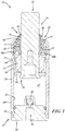
- FIG. 1 illustrates a gas spring 10 that may be used in forming equipment, for example, sheet metal stamping dies and mechanical presses (not shown).
- the gas spring 10 may include a casing 12, a guide and seal assembly 14 carried by the casing 12, a piston rod 16 carried by the casing 12 and extending through the guide and seal assembly 14, and a pressure chamber 17.
- An outer axial end of the piston rod 16 may be engageable with or by a die member or another portion of a press or piece of forming equipment (not shown).
- one or more of the gas springs 10 may be used in various implementations in forming equipment to provide a moveable component for support of a forming die or a workpiece with a yielding force or a return force.
- the gas spring 10 may provide a yielding force against a binder ring of a forming die to hold a metal workpiece while another part of the forming die forms, cuts, stretches, or bends the workpiece.
- the gas spring 10 may provide a yielding force and return force to lift a workpiece off of a surface of the forming die or to otherwise maintain control of the workpiece.
- the gas spring 10 may apply a yielding force to return a cam-activated tool to its home position.
- the gas spring 10 may be used in a wide range of other implementations.
- the gas spring 10 includes an overstroke or overtravel pressure relief component 18 in the event of an overtravel condition of the piston rod 16 of the gas spring 10.
- the overtravel pressure relief component 18 may be part of the guide and seal assembly 14, and may function to allow pressurized gas to be communicated out of the pressure chamber 17, to provide protection in an overtravel condition, including possible overpressure of gas in the pressure chamber 17.
- the overtravel pressure relief component 18 may be displaced so as to unseat a seal to release pressurized gas from within the pressure chamber 17 of the gas spring 10.
- the terminology "overtravel condition" includes a condition where a die member, or any other machine component with which the gas spring 10 interacts, causes the piston rod to be retracted into the casing 12 beyond a design intent position in the gas spring 10.
- the casing 12 may include a side wall 20 that may terminate axially at a closed end 22 and at an open end 24 that may receive the guide and seal assembly 14 and the piston rod 16 therein.
- the pressure chamber 17 is established at least in part by the side and end walls 20, 22 to receive a gas under pressure.
- the closed end 22 may be a separate component coupled to the side wall 20 and sealed thereto with a seal, for example, by crimping, swaging, or other forming.
- the closed end 22 may be coupled to the side wall 20 via a weld joint, or may be integrally produced with the side wall 20.
- the side wall 20 of the casing 12 has an inner surface 26 defining at least in part the pressure chamber 17, and an outer surface 28.
- the casing 12 may be of generally cylindrical shape, for example, wherein at least one of the inner or outer surfaces 26, 28 is cylindrical.
- the side wall 20 may have a circumferentially extending retainer bead 30 to axially retain at least a portion of the guide and seal assembly 14 to maintain the gas spring 10 in its assembled state.
- a pair of longitudinally spaced circumferential grooves 32, 34 may be machined, formed, or otherwise provided in the outer surface 28 of the casing 12.
- the casing 12 may include a passage or fill port 36 that may be provided through the closed end 22 of the casing 12 in any suitable manner.
- a fill valve 38 may be carried by the casing 12 to allow the gas spring 10 to be pressurized through the fill port 36 and to close the fill port 36 when the gas spring 10 is pressurized.
- the fill valve 38 may be a poppet valve, as illustrated, but instead may include a Schrader fill valve, or any other suitable type of valve in any suitable location at the closed end 22 of the casing 12.
- the guide and seal assembly 14 may be disposed in, or carried proximate to, the open end 24 of the casing 12 and may be sealingly coupled to the casing 12.
- the assembly 14 may include a bearing assembly that may include a piston rod housing 44 and a guide bearing 46 carried by the housing 44.
- the assembly 14 also may include a rod seal 48 that may be disposed between the housing 44 and the open end 24, a seal backup 47 that may be disposed between the rod seal 48 and the open end 24, a rod wiper 50 that may be carried between the seal backup 47 and the open end 24 and may protrude out of the open end 24, and a casing seal 51 that may include an O-ring that may be carried between a portion of the wiper 50 and the open end 24.
- the guide bearing 46 may include one or more components and may be sized to slidably engage the piston rod 16 to guide the piston rod 16 for axial reciprocation within the casing 12.
- the guide bearing 46 includes a bushing, which may be composed of any suitable low friction material.
- the piston rod seal 48 may include a U-cup seal having a radially outer lip 48a in contact with the interior surface 26 of the casing 12 and a radially inner lip 48b in contact with an exterior surface of the piston rod 16.
- the piston rod 16 is disposed at least in part in the casing 12 and through the guide and seal assembly 14 for reciprocation along an axis A between extended and retracted positions over a cycle of the gas spring 10 including a retraction stroke and an extension or return stroke.
- the piston rod 16 is acted on by pressurized gas in the pressure chamber 17 to bias the piston rod 16 toward the extended position, and away from the retracted position.
- the piston rod 16 extends out of the casing 12 through the guide and seal assembly housing 44, and includes an outer axial end 52, and an inner axial end 54 disposed in the casing 12 and that may be radially enlarged.
- a piston retainer 56 may be coupled to the inner axial end 54, for instance, via swaging of the piston rod 16 thereto.
- the retainer 56 may be engageable with a portion of the piston rod housing 44 to retain the piston rod 16 in the casing 12.
- the piston rod 16 is in sealing engagement with the rod seal 48 and in sliding engagement with the piston rod bearing 46 for guided relative movement between the extended and retracted positions.
- the overtravel pressure relief component 18 may include a collar 60, which may be slidably carried around the piston rod 16 at least partially axially between the guide and seal assembly 14 and the casing open end 24 and axially retained by the seal backup 47.
- the collar 60 is circumferentially continuous and has a cylindrical inner surface.
- the collar 60 includes an inner end 62 disposed axially inward with respect to the open end 24 of the housing 12 and contacting the piston rod seal 48, and an axially outer end 64 disposed axially beyond or outward with respect to the open end 24 of the housing 12.
- the collar 60 extends axially proud of or beyond the housing 44 and the casing 12 at the axially outer 64 thereof.
- the collar inner end 62 may be bayonet-shaped or wedge-shaped, for instance, including a barb with a shoulder, a cylindrical inner surface and an outer surface disposed at a non-zero angle with respect to the inner surface of the collar 60.
- the seal backup 47 includes an inner diameter smaller than an outer diameter of the collar inner end 62 so as to axially retain the collar 60 in the gas spring 10.
- the wiper 50 protrudes axially beyond the collar outer end 64 and may be engaged with the piston rod 16 such that the collar 60 is concealed by the wiper 50.
- the gas spring 10 may be assembled in any suitable manner and its various components may be manufactured in any suitable manner and composed of any suitable materials.
- the casing 12 may be turned, bored, drilled, tapped, and/or otherwise machined from a metal tube and/or metal bar stock such as steel.
- the collar 60 may be constructed from, for example, steel, brass, copper, carbon fiber, polymeric material, and/or any other suitable material(s).
- any suitable pressurizing device may be coupled to the port 36 to open the valve 38 and introduce pressurized gas into the port 36. Once a desired pressure is reached, the pressurizing device may be retracted to allow the valve 38 to close and thereby seal the pressurized gas within the pressure chamber 17.
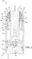
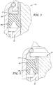
- FIG. 2 illustrates the gas spring 10 in a design intent maximum compression position of the piston rod 16 relative to the casing 12. As shown, in this position, an axially outermost surface of the piston rod 16 protrudes axially beyond an axially outermost surface of the overtravel relief component 18. Also, as shown in FIG. 3 , the overtravel relief component 18 has not moved relative to the seal 48.
- the die member or any other machine component may further axially displace the piston rod 16 into the casing 12.
- the machine component strikes the axially outer end 64 of the overtravel relief component 18, resulting in displacement thereof.
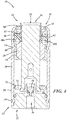
- Such axial displacement of the overtravel relief component 18 will result in radially outward displacement of a portion of the seal 48, thereby allowing pressurized gas in the chamber 17 to escape through a path between the piston rod 16 and the seal 48 to the exterior of the gas spring 10, as illustratively depicted in FIG. 4 and as more clearly shown in FIG. 5 .
- the collar 60 moves in an axially inward direction with respect to the piston rod seal 18 such that the collar inner end 62 radially displaces the inner lip 48b of the piston rod seal 48 to open an overpressure relief path to allow pressurized gas in the pressure chamber 17 to escape through the relief path to atmosphere outside the gas spring 10. More specifically, corresponding inclined/angled surfaces of the collar inner end 62 and the seal inner lip 48b cooperate such that relative axial movement therebetween causes radially outward movement of the seal 48 to unseat or breach sealing engagement between the seal 48 and the piston rod 16.
- FIG. 6 illustrates a gas spring 10' which has essentially the same construction and arrangement as the gas spring 10 except for a modified guide and seal assembly 14'.
- Components of the gas spring 10' which are essentially the same as those of gas spring 10 are identified with the same reference numbers as the corresponding components of the gas spring 10 and thus a description of these components will not be repeated.
- the modified guide and seal assembly 14' has an annular housing 44' slidably received in the casing 12 and removably retained therein by a split ring 70 of two segments received in complementary annular recesses 72 and 74 in the housing and the casing adjacent the open end.
- a rod wiper 50' is received in an annular recess 76 in the upper end of the housing 44'.
- a piston rod seal 48 is received and retained in an annular recess 78 in housing 44' which recess opens radially inward onto the piston rod 16.
- a seal between the housing 44' and the casing may be provided by an o-ring 80 and a backing ring 82 received in an annular groove 84 in the housing and opening radially outwardly onto the casing 12.
- the piston rod 16 may have an integral retainer 56' which in the fully extended position of the rod overlaps and bears on the inner end 86 of the housing 44' to provide a positive stop for the piston rod when it moves to its fully extended position.
- the overtravel pressure relief collar 60 is slidably received both over and around the piston rod 16 and in a bore 88 through the housing 44' which bore may be coaxial with the cylindrical casing wall 26.
- the collar 60 may also provide the only bearing guiding reciprocal movement of the piston rod 16 between its extended and retracted positions.
- the collar 60 may have a groove 92 opening radially inwardly onto the piston rod 116 for receiving and retaining a suitable lubricant for the bearing surfaces 94 of the collar.
- the collar 60 moves in an axially inward direction with respect to the rod seal 48 and displaces at least a portion of the inner lip 48b of the seal 48 from the rod 16 to open an overtravel pressure relief path allowing pressurized gas in the pressure chamber 17 to escape through this relief path to the atmosphere outside of the gas spring 10'.
- the gas spring 10' operates in the same manner as the gas spring 10 and thus its operation will not be repeated.
Landscapes
- Engineering & Computer Science (AREA)
- General Engineering & Computer Science (AREA)
- Mechanical Engineering (AREA)
- Fluid-Damping Devices (AREA)
- Safety Valves (AREA)
Claims (21)
- Ressort à gaz (10 ; 10') pour un équipement de formage, comprenant :un carter (12) comprenant une paroi latérale s'étendant axialement (20) avec une surface intérieure (26), une extrémité ouverte (24), une paroi d'extrémité fermée s'étendant transversalement (22) espacée axialement de l'extrémité ouverte (24), et une chambre de pression (17) établie en partie par la paroi latérale (20) et la paroi d'extrémité fermée (22) pour y recevoir un gaz sous pression ;un boîtier de tige de piston (44 ; 44') comprenant une extrémité intérieure (86) et une extrémité extérieure espacée axialement de l'extrémité intérieure (86) et le boîtier de tige de piston (44 ; 44') est reçu dans le carter (12) adjacent à l'extrémité ouverte (24) du carter (12) ;une tige de piston (16) s'étendant à travers le boîtier de tige de piston (44 ; 44') et ayant une extrémité intérieure (54) reçue dans la chambre de pression (17) et une extrémité extérieure (52) normalement à l'extérieur du carter (12) ; et caractérisé parun joint de tige de piston (48) entourant et portant sur la tige de piston (16), comprenant une lèvre intérieure (48b) dans une mise en prise d'étanchéification avec la tige de piston (16) et une lèvre extérieure (48a) dans une mise en prise d'étanchéification avec un du boîtier de tige de piston (44 ; 44') ou du carter (12) et procurant un joint d'étanchéité entre la tige de piston (16) et l'un d'un tel carter (12) ou boîtier de tige de piston (44 ; 44') ;un collet de décharge de pression de dépassement de course (60) reçu de manière coulissante autour de la tige de piston (16) et ayant une extrémité extérieure de collet (64) qui fait saillie axialement au-delà de l'extrémité ouverte (24) du carter (12) et une extrémité intérieure de collet (62) conçue pour entrer en contact avec au moins une partie du joint de tige de piston (48) de sorte que généralement, pendant une condition de dépassement de course de la tige de piston (16), un mouvement axial du collet (60) vers l'extrémité fermée (22) du carter (12) déplace au moins une partie du joint de tige de piston (48) de la tige de piston (16) pour procurer un passage pour l'échappement d'un gaz sous pression de la chambre de pression (17) vers l'extérieur du ressort à gaz (10 ; 10').
- Ressort à gaz (10) selon la revendication 1, comprenant en outre :un palier de tige de piston (46) porté par le boîtier de tige de piston (44) ; la tige de piston (16) reçue de manière coulissante dans le palier de tige de piston (46) pour un mouvement de va-et-vient entre les positions étendue et rétractée ; etle joint de tige de piston (48) porté entre un ensemble palier et l'extrémité ouverte de carter (24).
- Ressort à gaz (10) selon la revendication 2, dans lequel le joint de tige de piston (48) est un joint en coupelle en U ayant lèvre radialement extérieure (48a) en contact avec une surface intérieure (26) du carter (12) et une lèvre radialement intérieure (48b) en contact avec une surface extérieure de la tige de piston (16).
- Ressort à gaz (10) selon la revendication 2 ou 3, dans lequel l'extrémité intérieure de collet (62) du collet de décharge de pression de dépassement de course (60) est en forme de baïonnette.
- Ressort à gaz (10) selon l'une des revendications 2 à 4, comprenant en outre un appui de joint (47) placé entre le joint de tige de piston (48) et l'extrémité ouverte (24) du carter (12) et comprenant un diamètre intérieur inférieur au diamètre extérieur de l'extrémité intérieure de collet (62) de manière à retenir axialement le collet (60) dans le ressort à gaz (10).
- Ressort à gaz (10) selon l'une des revendications 2 à 5, comprenant en outre un racleur (50) porté à l'extrémité ouverte (24) du carter (12) et faisant saillie axialement au-delà de l'extrémité extérieure de collet (64) et en prise avec la tige de piston (16) de sorte que le collet (60) est masqué par le racleur (50).
- Ressort à gaz (10) selon l'une des revendications 2 à 6, dans lequel la lèvre extérieure (48a) est en contact avec une surface intérieure (26) du carter (12) et la lèvre intérieure (48b) est en contact avec une surface extérieure de la tige de piston (16).
- Ressort à gaz (10) selon la revendication 7, dans lequel, pendant une condition de dépassement de course, le collet (60) se déplace dans une direction axialement vers l'intérieur par rapport au joint de tige de piston (48) de sorte que l'extrémité intérieure de collet (62) déplace radialement la lèvre intérieure (48b) du joint de tige de piston (48) pour ouvrir un passage de décharge de surpression pour permettre au gaz sous pression dans la chambre de pression (17) de s'échapper par le passage de décharge vers l'atmosphère à l'extérieur du ressort à gaz (10).
- Ressort à gaz (10) selon l'une des revendications 2 à 8, dans lequel, pendant une condition de dépassement de course, le collet (60) se déplace dans une direction axialement vers l'intérieur par rapport au joint de tige de piston (48) de sorte que le collet (60) déplace radialement une partie du joint de tige de piston (48) pour ouvrir un passage de décharge de surpression pour permettre au gaz sous pression dans la chambre de pression (17) de s'échapper par le passage de décharge vers l'atmosphère à l'extérieur du ressort à gaz (10).
- Ressort à gaz (10) selon l'une des revendications 2 à 9, dans lequel le collet de décharge de pression de dépassement de course (60) procure également l'ensemble palier pour la tige de piston (16).
- Ressort à gaz (10) selon la revendication 10, dans lequel le collet de décharge de pression de dépassement de course (60) comprend également une rainure annulaire s'ouvrant sur la tige de piston (16) pour y recevoir un lubrifiant.
- Ressort à gaz (10) selon l'une des revendications 2 à 11, comprenant l'ensemble palier porté à l'intérieur du carter (12), et comprenant :le boîtier de tige de piston (44) etle palier de tige de piston (46), dans lequelle collet de décharge de pression de dépassement de course (60) est porté de manière coulissante autour de la tige de piston (16) au moins partiellement axialement entre l'ensemble palier et l'extrémité ouverte du carter (24) et a une extrémité extérieure de collet (64) qui fait saillie axialement au-delà du boîtier de tige de piston (44) et une extrémité intérieure de collet (62) entrant en contact avec le joint de tige de piston (48).
- Ressort à gaz (10') selon la revendication 1, lequel comprenant en outre :le joint de tige de piston (48) porté par le boîtier (44') et procurant un joint d'étanchéité entre la tige de piston (16) et le boîtier (44') ; etun joint d'étanchéité porté par le boîtier (44') et procurant un joint d'étanchéité entre le boîtier (44') et le carter (12).
- Ressort à gaz (10') selon la revendication 13, dans lequel le joint de tige de piston (48) est un joint en coupelle en U ayant une lèvre radialement extérieure (48a) en contact avec une surface intérieure du boîtier de tige de piston (44') et une lèvre radialement intérieure (48b) en contact avec une surface extérieure de la tige de piston (16).
- Ressort à gaz (10') selon la revendication 13 ou 14, dans lequel l'extrémité intérieure (62) du collet de décharge de pression de dépassement de course (60) est en forme de baïonnette.
- Ressort à gaz (10') selon l'une des revendications 13 à 15, dans lequel une partie du collet (60) adjacent à son extrémité intérieure (62) chevauche une partie du boîtier (44') pour retenir le collet (60) dans le ressort à gaz (10').
- Ressort à gaz (10') selon l'une des revendications 13 à 16, comprenant en outre un racleur de tige de piston (50') porté par le collet (60) adjacent à l'extrémité ouverte du carter (24) et faisant saillie axialement au-delà de l'extrémité extérieure de collet (64) et en prise avec la tige de piston (16).
- Ressort à gaz (10') selon l'une des revendications 13 à 17, dans lequel la lèvre extérieure (48a) est en contact avec une surface intérieure du boîtier (44') et la lèvre intérieure (48b) est en contact avec une surface extérieure de la tige de piston (16).
- Ressort à gaz (10') selon la revendication 18, dans lequel, pendant une condition de dépassement de course, le collet (60) se déplace dans une direction axialement vers l'intérieur par rapport au joint de tige de piston (48) pour ouvrir un passage de décharge de surpression pour permettre au gaz sous pression dans la chambre de pression (17) de s'échapper par le passage de décharge vers l'atmosphère à l'extérieur du ressort à gaz (10').
- Ressort à gaz (10') selon l'une des revendications 13 à 19, dans lequel, pendant une condition de dépassement de course, le collet (60) se déplace dans une direction axialement vers l'intérieur par rapport au joint de tige de piston (48) de sorte que le collet (60) déplace radialement une partie du joint de tige de piston (48) pour ouvrir un passage de décharge de surpression pour permettre au gaz sous pression dans la chambre de pression (17) de s'échapper par le passage de décharge vers l'atmosphère à l'extérieur du ressort à gaz (10').
- Ressort à gaz (10') selon l'une des revendications 13 à 20, dans lequel le collet de décharge de pression de dépassement de course (60) est porté de manière coulissante par le boîtier (44').
Applications Claiming Priority (2)
| Application Number | Priority Date | Filing Date | Title |
|---|---|---|---|
| US201662395729P | 2016-09-16 | 2016-09-16 | |
| US15/699,591 US10527121B2 (en) | 2016-09-16 | 2017-09-08 | Overtravel pressure relief for a gas spring |
Publications (2)
| Publication Number | Publication Date |
|---|---|
| EP3296589A1 EP3296589A1 (fr) | 2018-03-21 |
| EP3296589B1 true EP3296589B1 (fr) | 2019-12-11 |
Family
ID=59858986
Family Applications (1)
| Application Number | Title | Priority Date | Filing Date |
|---|---|---|---|
| EP17191093.8A Active EP3296589B1 (fr) | 2016-09-16 | 2017-09-14 | Décharge de pression de dépassement de course pour ressort à gaz |
Country Status (8)
| Country | Link |
|---|---|
| US (1) | US10527121B2 (fr) |
| EP (1) | EP3296589B1 (fr) |
| JP (1) | JP6961182B2 (fr) |
| KR (1) | KR102405027B1 (fr) |
| CN (1) | CN109790899B (fr) |
| ES (1) | ES2777782T3 (fr) |
| TW (1) | TWI675156B (fr) |
| WO (1) | WO2018052924A1 (fr) |
Families Citing this family (5)
| Publication number | Priority date | Publication date | Assignee | Title |
|---|---|---|---|---|
| TWI870253B (zh) | 2019-03-20 | 2025-01-11 | 美商黛寇公司 | 具有超程釋壓功能之氣彈簧 |
| US11504759B2 (en) | 2019-07-22 | 2022-11-22 | Anchor Lamina America, Inc. | Stamping dies and guided retainer devices for use in same |
| JP7341917B2 (ja) * | 2020-02-06 | 2023-09-11 | Kyb株式会社 | 緩衝器 |
| US12697650B2 (en) * | 2021-10-08 | 2026-08-04 | Standard Lifters, Inc. | Wiper cap assembly |
| KR102812330B1 (ko) * | 2024-05-23 | 2025-05-22 | 박흥식 | 고품위 가스 실린더 |
Family Cites Families (20)
| Publication number | Priority date | Publication date | Assignee | Title |
|---|---|---|---|---|
| US4792128A (en) * | 1988-03-08 | 1988-12-20 | Power Components, Inc. | No grow gas spring |
| US5088698A (en) * | 1989-11-08 | 1992-02-18 | Wallis Bernard J | Sealing construction for a gas spring |
| US5275387A (en) * | 1992-04-09 | 1994-01-04 | Power Components, Inc. | Gas spring |
| US5344125A (en) * | 1993-09-17 | 1994-09-06 | Diebolt International, Inc. | Gas spring with filler valve |
| DE9400669U1 (de) * | 1994-01-17 | 1994-03-24 | Iska Wolfgang Katz Verwaltungs-Gmbh, 78083 Dauchingen | Gasfederelement |
| US6003848A (en) * | 1997-07-01 | 1999-12-21 | Diebolt International, Inc. | Compact gas spring |
| FR2779194B1 (fr) * | 1998-05-28 | 2000-08-11 | Orflam Ind | Dispositif a fluide compressible |
| US6491143B1 (en) * | 1999-12-30 | 2002-12-10 | Diebolt International, Inc. | Low impact gas spring |
| US7559542B2 (en) * | 2004-08-19 | 2009-07-14 | Diebolt International, Inc. | Low impact gas spring |
| US8444122B2 (en) * | 2007-09-13 | 2013-05-21 | Dadco, Inc. | Gas spring with guide |
| TR200807829A2 (tr) | 2008-10-17 | 2009-07-21 | Destek Otomoti̇v Yan Sanayi̇ Ve Ti̇caret Anoni̇m Şi̇rketi̇ | Gazlı yaylar için bir emniyet tertibatı |
| US8490763B2 (en) * | 2009-03-10 | 2013-07-23 | Dadco, Inc. | Delay return gas spring |
| US9046146B2 (en) * | 2012-02-14 | 2015-06-02 | Dadco, Inc. | Gas spring and gas spring components |
| EP2634451B1 (fr) * | 2012-03-01 | 2018-05-23 | Special Springs S.r.l. | Actionneur à vérin à gaz avec dispositif de sécurité de dépassement de course |
| US9194501B2 (en) * | 2012-11-20 | 2015-11-24 | Dresser, Inc. | Pressure balanced spring loaded overtravel sealing apparatus |
| US20140191452A1 (en) * | 2013-01-10 | 2014-07-10 | Dadco, Inc. | Gas Spring and Overpressure Relief and Fill Valve Assembly |
| US9347510B2 (en) | 2013-03-15 | 2016-05-24 | Dadco, Inc. | Overtravel pressure relief for a gas spring |
| US9447834B2 (en) * | 2013-09-19 | 2016-09-20 | Dadco, Inc. | Overtravel pressure relief for a gas spring |
| US20150076753A1 (en) * | 2013-09-19 | 2015-03-19 | Dadco, Inc. | Overtravel Pressure Relief For A Gas Spring |
| EP3051173B1 (fr) | 2015-01-28 | 2019-06-26 | Dadco, Inc. | Decharge de pression de depassement de course pour ressort a gaz |
-
2017
- 2017-09-08 US US15/699,591 patent/US10527121B2/en active Active
- 2017-09-13 WO PCT/US2017/051253 patent/WO2018052924A1/fr not_active Ceased
- 2017-09-13 CN CN201780057023.8A patent/CN109790899B/zh active Active
- 2017-09-13 JP JP2019514719A patent/JP6961182B2/ja active Active
- 2017-09-13 KR KR1020197010717A patent/KR102405027B1/ko active Active
- 2017-09-14 EP EP17191093.8A patent/EP3296589B1/fr active Active
- 2017-09-14 ES ES17191093T patent/ES2777782T3/es active Active
- 2017-09-14 TW TW106131583A patent/TWI675156B/zh active
Non-Patent Citations (1)
| Title |
|---|
| None * |
Also Published As
| Publication number | Publication date |
|---|---|
| WO2018052924A1 (fr) | 2018-03-22 |
| JP6961182B2 (ja) | 2021-11-05 |
| ES2777782T3 (es) | 2020-08-06 |
| KR20190051038A (ko) | 2019-05-14 |
| US20180080519A1 (en) | 2018-03-22 |
| TW201814179A (zh) | 2018-04-16 |
| EP3296589A1 (fr) | 2018-03-21 |
| US10527121B2 (en) | 2020-01-07 |
| KR102405027B1 (ko) | 2022-06-07 |
| JP2019529829A (ja) | 2019-10-17 |
| CN109790899B (zh) | 2021-03-05 |
| CN109790899A (zh) | 2019-05-21 |
| TWI675156B (zh) | 2019-10-21 |
| BR112019005143A2 (pt) | 2019-06-04 |
Similar Documents
| Publication | Publication Date | Title |
|---|---|---|
| EP2857711B1 (fr) | Décharge de pression de dépassement de course pour ressort à gaz | |
| US10527121B2 (en) | Overtravel pressure relief for a gas spring | |
| EP2754917A2 (fr) | Ressort à gaz et surpression et ensemble de vanne de remplissage | |
| US10113605B2 (en) | Overtravel relief assembly for a gas spring | |
| EP2754915A2 (fr) | Ressort à gaz et bouchon de surpression | |
| EP2037148B1 (fr) | Ressort à gaz avec guide | |
| US9447834B2 (en) | Overtravel pressure relief for a gas spring | |
| US20130207326A1 (en) | Gas Spring and Gas Spring Components | |
| EP3051173B1 (fr) | Decharge de pression de depassement de course pour ressort a gaz | |
| RU2737877C1 (ru) | Поршневой узел и гидро(пневмо)устройство | |
| BR112019005143B1 (pt) | Mola a gás para equipamento de formação |
Legal Events
| Date | Code | Title | Description |
|---|---|---|---|
| PUAI | Public reference made under article 153(3) epc to a published international application that has entered the european phase |
Free format text: ORIGINAL CODE: 0009012 |
|
| STAA | Information on the status of an ep patent application or granted ep patent |
Free format text: STATUS: THE APPLICATION HAS BEEN PUBLISHED |
|
| AK | Designated contracting states |
Kind code of ref document: A1 Designated state(s): AL AT BE BG CH CY CZ DE DK EE ES FI FR GB GR HR HU IE IS IT LI LT LU LV MC MK MT NL NO PL PT RO RS SE SI SK SM TR |
|
| AX | Request for extension of the european patent |
Extension state: BA ME |
|
| STAA | Information on the status of an ep patent application or granted ep patent |
Free format text: STATUS: REQUEST FOR EXAMINATION WAS MADE |
|
| 17P | Request for examination filed |
Effective date: 20180904 |
|
| RBV | Designated contracting states (corrected) |
Designated state(s): AL AT BE BG CH CY CZ DE DK EE ES FI FR GB GR HR HU IE IS IT LI LT LU LV MC MK MT NL NO PL PT RO RS SE SI SK SM TR |
|
| RIC1 | Information provided on ipc code assigned before grant |
Ipc: F16F 9/43 20060101ALI20181204BHEP Ipc: F16F 9/02 20060101AFI20181204BHEP |
|
| GRAP | Despatch of communication of intention to grant a patent |
Free format text: ORIGINAL CODE: EPIDOSNIGR1 |
|
| STAA | Information on the status of an ep patent application or granted ep patent |
Free format text: STATUS: GRANT OF PATENT IS INTENDED |
|
| RAP1 | Party data changed (applicant data changed or rights of an application transferred) |
Owner name: DADCO, INC. |
|
| RIN1 | Information on inventor provided before grant (corrected) |
Inventor name: COTTER, JONATHAN P. |
|
| INTG | Intention to grant announced |
Effective date: 20190212 |
|
| GRAJ | Information related to disapproval of communication of intention to grant by the applicant or resumption of examination proceedings by the epo deleted |
Free format text: ORIGINAL CODE: EPIDOSDIGR1 |
|
| STAA | Information on the status of an ep patent application or granted ep patent |
Free format text: STATUS: REQUEST FOR EXAMINATION WAS MADE |
|
| GRAJ | Information related to disapproval of communication of intention to grant by the applicant or resumption of examination proceedings by the epo deleted |
Free format text: ORIGINAL CODE: EPIDOSDIGR1 |
|
| STAA | Information on the status of an ep patent application or granted ep patent |
Free format text: STATUS: GRANT OF PATENT IS INTENDED |
|
| GRAP | Despatch of communication of intention to grant a patent |
Free format text: ORIGINAL CODE: EPIDOSNIGR1 |
|
| INTC | Intention to grant announced (deleted) | ||
| INTG | Intention to grant announced |
Effective date: 20190701 |
|
| GRAS | Grant fee paid |
Free format text: ORIGINAL CODE: EPIDOSNIGR3 |
|
| GRAA | (expected) grant |
Free format text: ORIGINAL CODE: 0009210 |
|
| STAA | Information on the status of an ep patent application or granted ep patent |
Free format text: STATUS: THE PATENT HAS BEEN GRANTED |
|
| AK | Designated contracting states |
Kind code of ref document: B1 Designated state(s): AL AT BE BG CH CY CZ DE DK EE ES FI FR GB GR HR HU IE IS IT LI LT LU LV MC MK MT NL NO PL PT RO RS SE SI SK SM TR |
|
| REG | Reference to a national code |
Ref country code: GB Ref legal event code: FG4D |
|
| REG | Reference to a national code |
Ref country code: CH Ref legal event code: EP |
|
| REG | Reference to a national code |
Ref country code: AT Ref legal event code: REF Ref document number: 1212498 Country of ref document: AT Kind code of ref document: T Effective date: 20191215 |
|
| REG | Reference to a national code |
Ref country code: DE Ref legal event code: R096 Ref document number: 602017009547 Country of ref document: DE |
|
| REG | Reference to a national code |
Ref country code: IE Ref legal event code: FG4D |
|
| REG | Reference to a national code |
Ref country code: SE Ref legal event code: TRGR |
|
| REG | Reference to a national code |
Ref country code: NL Ref legal event code: MP Effective date: 20191211 |
|
| REG | Reference to a national code |
Ref country code: LT Ref legal event code: MG4D |
|
| PG25 | Lapsed in a contracting state [announced via postgrant information from national office to epo] |
Ref country code: NO Free format text: LAPSE BECAUSE OF FAILURE TO SUBMIT A TRANSLATION OF THE DESCRIPTION OR TO PAY THE FEE WITHIN THE PRESCRIBED TIME-LIMIT Effective date: 20200311 Ref country code: FI Free format text: LAPSE BECAUSE OF FAILURE TO SUBMIT A TRANSLATION OF THE DESCRIPTION OR TO PAY THE FEE WITHIN THE PRESCRIBED TIME-LIMIT Effective date: 20191211 Ref country code: BG Free format text: LAPSE BECAUSE OF FAILURE TO SUBMIT A TRANSLATION OF THE DESCRIPTION OR TO PAY THE FEE WITHIN THE PRESCRIBED TIME-LIMIT Effective date: 20200311 Ref country code: GR Free format text: LAPSE BECAUSE OF FAILURE TO SUBMIT A TRANSLATION OF THE DESCRIPTION OR TO PAY THE FEE WITHIN THE PRESCRIBED TIME-LIMIT Effective date: 20200312 Ref country code: LT Free format text: LAPSE BECAUSE OF FAILURE TO SUBMIT A TRANSLATION OF THE DESCRIPTION OR TO PAY THE FEE WITHIN THE PRESCRIBED TIME-LIMIT Effective date: 20191211 Ref country code: LV Free format text: LAPSE BECAUSE OF FAILURE TO SUBMIT A TRANSLATION OF THE DESCRIPTION OR TO PAY THE FEE WITHIN THE PRESCRIBED TIME-LIMIT Effective date: 20191211 |
|
| PG25 | Lapsed in a contracting state [announced via postgrant information from national office to epo] |
Ref country code: RS Free format text: LAPSE BECAUSE OF FAILURE TO SUBMIT A TRANSLATION OF THE DESCRIPTION OR TO PAY THE FEE WITHIN THE PRESCRIBED TIME-LIMIT Effective date: 20191211 Ref country code: HR Free format text: LAPSE BECAUSE OF FAILURE TO SUBMIT A TRANSLATION OF THE DESCRIPTION OR TO PAY THE FEE WITHIN THE PRESCRIBED TIME-LIMIT Effective date: 20191211 |
|
| PG25 | Lapsed in a contracting state [announced via postgrant information from national office to epo] |
Ref country code: AL Free format text: LAPSE BECAUSE OF FAILURE TO SUBMIT A TRANSLATION OF THE DESCRIPTION OR TO PAY THE FEE WITHIN THE PRESCRIBED TIME-LIMIT Effective date: 20191211 |
|
| PG25 | Lapsed in a contracting state [announced via postgrant information from national office to epo] |
Ref country code: NL Free format text: LAPSE BECAUSE OF FAILURE TO SUBMIT A TRANSLATION OF THE DESCRIPTION OR TO PAY THE FEE WITHIN THE PRESCRIBED TIME-LIMIT Effective date: 20191211 Ref country code: RO Free format text: LAPSE BECAUSE OF FAILURE TO SUBMIT A TRANSLATION OF THE DESCRIPTION OR TO PAY THE FEE WITHIN THE PRESCRIBED TIME-LIMIT Effective date: 20191211 Ref country code: CZ Free format text: LAPSE BECAUSE OF FAILURE TO SUBMIT A TRANSLATION OF THE DESCRIPTION OR TO PAY THE FEE WITHIN THE PRESCRIBED TIME-LIMIT Effective date: 20191211 Ref country code: PT Free format text: LAPSE BECAUSE OF FAILURE TO SUBMIT A TRANSLATION OF THE DESCRIPTION OR TO PAY THE FEE WITHIN THE PRESCRIBED TIME-LIMIT Effective date: 20200506 Ref country code: EE Free format text: LAPSE BECAUSE OF FAILURE TO SUBMIT A TRANSLATION OF THE DESCRIPTION OR TO PAY THE FEE WITHIN THE PRESCRIBED TIME-LIMIT Effective date: 20191211 |
|
| REG | Reference to a national code |
Ref country code: ES Ref legal event code: FG2A Ref document number: 2777782 Country of ref document: ES Kind code of ref document: T3 Effective date: 20200806 |
|
| PG25 | Lapsed in a contracting state [announced via postgrant information from national office to epo] |
Ref country code: SK Free format text: LAPSE BECAUSE OF FAILURE TO SUBMIT A TRANSLATION OF THE DESCRIPTION OR TO PAY THE FEE WITHIN THE PRESCRIBED TIME-LIMIT Effective date: 20191211 Ref country code: IS Free format text: LAPSE BECAUSE OF FAILURE TO SUBMIT A TRANSLATION OF THE DESCRIPTION OR TO PAY THE FEE WITHIN THE PRESCRIBED TIME-LIMIT Effective date: 20200411 Ref country code: SM Free format text: LAPSE BECAUSE OF FAILURE TO SUBMIT A TRANSLATION OF THE DESCRIPTION OR TO PAY THE FEE WITHIN THE PRESCRIBED TIME-LIMIT Effective date: 20191211 |
|
| REG | Reference to a national code |
Ref country code: DE Ref legal event code: R097 Ref document number: 602017009547 Country of ref document: DE |
|
| REG | Reference to a national code |
Ref country code: AT Ref legal event code: MK05 Ref document number: 1212498 Country of ref document: AT Kind code of ref document: T Effective date: 20191211 |
|
| PLBE | No opposition filed within time limit |
Free format text: ORIGINAL CODE: 0009261 |
|
| STAA | Information on the status of an ep patent application or granted ep patent |
Free format text: STATUS: NO OPPOSITION FILED WITHIN TIME LIMIT |
|
| PG25 | Lapsed in a contracting state [announced via postgrant information from national office to epo] |
Ref country code: DK Free format text: LAPSE BECAUSE OF FAILURE TO SUBMIT A TRANSLATION OF THE DESCRIPTION OR TO PAY THE FEE WITHIN THE PRESCRIBED TIME-LIMIT Effective date: 20191211 |
|
| 26N | No opposition filed |
Effective date: 20200914 |
|
| PG25 | Lapsed in a contracting state [announced via postgrant information from national office to epo] |
Ref country code: AT Free format text: LAPSE BECAUSE OF FAILURE TO SUBMIT A TRANSLATION OF THE DESCRIPTION OR TO PAY THE FEE WITHIN THE PRESCRIBED TIME-LIMIT Effective date: 20191211 Ref country code: SI Free format text: LAPSE BECAUSE OF FAILURE TO SUBMIT A TRANSLATION OF THE DESCRIPTION OR TO PAY THE FEE WITHIN THE PRESCRIBED TIME-LIMIT Effective date: 20191211 |
|
| PG25 | Lapsed in a contracting state [announced via postgrant information from national office to epo] |
Ref country code: PL Free format text: LAPSE BECAUSE OF FAILURE TO SUBMIT A TRANSLATION OF THE DESCRIPTION OR TO PAY THE FEE WITHIN THE PRESCRIBED TIME-LIMIT Effective date: 20191211 |
|
| REG | Reference to a national code |
Ref country code: CH Ref legal event code: PL |
|
| REG | Reference to a national code |
Ref country code: BE Ref legal event code: MM Effective date: 20200930 |
|
| PG25 | Lapsed in a contracting state [announced via postgrant information from national office to epo] |
Ref country code: LU Free format text: LAPSE BECAUSE OF NON-PAYMENT OF DUE FEES Effective date: 20200914 |
|
| PG25 | Lapsed in a contracting state [announced via postgrant information from national office to epo] |
Ref country code: CH Free format text: LAPSE BECAUSE OF NON-PAYMENT OF DUE FEES Effective date: 20200930 Ref country code: BE Free format text: LAPSE BECAUSE OF NON-PAYMENT OF DUE FEES Effective date: 20200930 Ref country code: LI Free format text: LAPSE BECAUSE OF NON-PAYMENT OF DUE FEES Effective date: 20200930 Ref country code: IE Free format text: LAPSE BECAUSE OF NON-PAYMENT OF DUE FEES Effective date: 20200914 |
|
| PG25 | Lapsed in a contracting state [announced via postgrant information from national office to epo] |
Ref country code: MT Free format text: LAPSE BECAUSE OF FAILURE TO SUBMIT A TRANSLATION OF THE DESCRIPTION OR TO PAY THE FEE WITHIN THE PRESCRIBED TIME-LIMIT Effective date: 20191211 Ref country code: CY Free format text: LAPSE BECAUSE OF FAILURE TO SUBMIT A TRANSLATION OF THE DESCRIPTION OR TO PAY THE FEE WITHIN THE PRESCRIBED TIME-LIMIT Effective date: 20191211 |
|
| PG25 | Lapsed in a contracting state [announced via postgrant information from national office to epo] |
Ref country code: MK Free format text: LAPSE BECAUSE OF FAILURE TO SUBMIT A TRANSLATION OF THE DESCRIPTION OR TO PAY THE FEE WITHIN THE PRESCRIBED TIME-LIMIT Effective date: 20191211 Ref country code: MC Free format text: LAPSE BECAUSE OF FAILURE TO SUBMIT A TRANSLATION OF THE DESCRIPTION OR TO PAY THE FEE WITHIN THE PRESCRIBED TIME-LIMIT Effective date: 20191211 |
|
| PGFP | Annual fee paid to national office [announced via postgrant information from national office to epo] |
Ref country code: DE Payment date: 20250929 Year of fee payment: 9 |
|
| PGFP | Annual fee paid to national office [announced via postgrant information from national office to epo] |
Ref country code: TR Payment date: 20250822 Year of fee payment: 9 Ref country code: IT Payment date: 20250919 Year of fee payment: 9 |
|
| PGFP | Annual fee paid to national office [announced via postgrant information from national office to epo] |
Ref country code: GB Payment date: 20250929 Year of fee payment: 9 |
|
| PGFP | Annual fee paid to national office [announced via postgrant information from national office to epo] |
Ref country code: FR Payment date: 20250925 Year of fee payment: 9 |
|
| PGFP | Annual fee paid to national office [announced via postgrant information from national office to epo] |
Ref country code: SE Payment date: 20250927 Year of fee payment: 9 |
|
| PGFP | Annual fee paid to national office [announced via postgrant information from national office to epo] |
Ref country code: ES Payment date: 20251001 Year of fee payment: 9 |