EP3296614B1 - Led-beleuchtungsvorrichtung mit verbessertem led-halter - Google Patents
Led-beleuchtungsvorrichtung mit verbessertem led-halter Download PDFInfo
- Publication number
- EP3296614B1 EP3296614B1 EP17191071.4A EP17191071A EP3296614B1 EP 3296614 B1 EP3296614 B1 EP 3296614B1 EP 17191071 A EP17191071 A EP 17191071A EP 3296614 B1 EP3296614 B1 EP 3296614B1
- Authority
- EP
- European Patent Office
- Prior art keywords
- holding structure
- section
- lighting device
- connection section
- attachment section
- Prior art date
- Legal status (The legal status is an assumption and is not a legal conclusion. Google has not performed a legal analysis and makes no representation as to the accuracy of the status listed.)
- Active
Links
Images
Classifications
-
- F—MECHANICAL ENGINEERING; LIGHTING; HEATING; WEAPONS; BLASTING
- F21—LIGHTING
- F21K—NON-ELECTRIC LIGHT SOURCES USING LUMINESCENCE; LIGHT SOURCES USING ELECTROCHEMILUMINESCENCE; LIGHT SOURCES USING CHARGES OF COMBUSTIBLE MATERIAL; LIGHT SOURCES USING SEMICONDUCTOR DEVICES AS LIGHT-GENERATING ELEMENTS; LIGHT SOURCES NOT OTHERWISE PROVIDED FOR
- F21K9/00—Light sources using semiconductor devices as light-generating elements, e.g. using light-emitting diodes [LED] or lasers
- F21K9/20—Light sources comprising attachment means
- F21K9/23—Retrofit light sources for lighting devices with a single fitting for each light source, e.g. for substitution of incandescent lamps with bayonet or threaded fittings
- F21K9/232—Retrofit light sources for lighting devices with a single fitting for each light source, e.g. for substitution of incandescent lamps with bayonet or threaded fittings specially adapted for generating an essentially omnidirectional light distribution, e.g. with a glass bulb
-
- F—MECHANICAL ENGINEERING; LIGHTING; HEATING; WEAPONS; BLASTING
- F21—LIGHTING
- F21K—NON-ELECTRIC LIGHT SOURCES USING LUMINESCENCE; LIGHT SOURCES USING ELECTROCHEMILUMINESCENCE; LIGHT SOURCES USING CHARGES OF COMBUSTIBLE MATERIAL; LIGHT SOURCES USING SEMICONDUCTOR DEVICES AS LIGHT-GENERATING ELEMENTS; LIGHT SOURCES NOT OTHERWISE PROVIDED FOR
- F21K9/00—Light sources using semiconductor devices as light-generating elements, e.g. using light-emitting diodes [LED] or lasers
- F21K9/20—Light sources comprising attachment means
- F21K9/23—Retrofit light sources for lighting devices with a single fitting for each light source, e.g. for substitution of incandescent lamps with bayonet or threaded fittings
- F21K9/237—Details of housings or cases, i.e. the parts between the light-generating element and the bases; Arrangement of components within housings or cases
-
- F—MECHANICAL ENGINEERING; LIGHTING; HEATING; WEAPONS; BLASTING
- F21—LIGHTING
- F21K—NON-ELECTRIC LIGHT SOURCES USING LUMINESCENCE; LIGHT SOURCES USING ELECTROCHEMILUMINESCENCE; LIGHT SOURCES USING CHARGES OF COMBUSTIBLE MATERIAL; LIGHT SOURCES USING SEMICONDUCTOR DEVICES AS LIGHT-GENERATING ELEMENTS; LIGHT SOURCES NOT OTHERWISE PROVIDED FOR
- F21K9/00—Light sources using semiconductor devices as light-generating elements, e.g. using light-emitting diodes [LED] or lasers
- F21K9/20—Light sources comprising attachment means
- F21K9/23—Retrofit light sources for lighting devices with a single fitting for each light source, e.g. for substitution of incandescent lamps with bayonet or threaded fittings
- F21K9/238—Arrangement or mounting of circuit elements integrated in the light source
-
- F—MECHANICAL ENGINEERING; LIGHTING; HEATING; WEAPONS; BLASTING
- F21—LIGHTING
- F21Y—INDEXING SCHEME ASSOCIATED WITH SUBCLASSES F21K, F21L, F21S and F21V, RELATING TO THE FORM OR THE KIND OF THE LIGHT SOURCES OR OF THE COLOUR OF THE LIGHT EMITTED
- F21Y2115/00—Light-generating elements of semiconductor light sources
- F21Y2115/10—Light-emitting diodes [LED]
Definitions
- the present invention relates to a LED lighting device, in particular a lighting device using LED filaments which are attached to an improved holder.
- a specific type of LED lighting devices uses LED filaments, i.e. strip-like LED elements which typically comprise a plurality of LEDs arranged in a row on a transparent strip-like carrier (e.g. glass or sapphire materials).
- the LEDs may be coated by a coating for converting the light generated by the LEDs into a desired wavelength range.
- Multiple LED filaments are usually arranged inside a bulb of a lighting device. For ensuring a specific arrangement of the LED filaments with respect to each other and for supplying the LED filaments with electrical power a holder is needed.
- a lighting device comprises a translucent bulb, in particular a transparent bulb, a base having at least two electrical contacts, and a light engine arranged inside the bulb.
- the bulb can be made from glass or a plastic material.
- the base can for example be a screw base (e.g. E14), a bayonet base (e.g. GU10), a bi-pin base (e.g. G4), or any other type of lamp base.
- the light engine inside the bulb comprises four or more LED filaments attached to a holder.
- the light engine may comprise 4, 5, 6, 7, 8 or any other number of LED filaments.
- the LED filaments are arranged such that not all LED filaments are positioned parallel to each other, in order to minimize the generation of shadows.
- the holder has a first electrically conductive holding structure and a second electrically conductive holding structure.
- Each LED filament is connected with a first end to the first holding structure and with a second end to the second holding structure. Apart from the connection via the LED filaments, the first holding structure and the second holding structure are electrically isolated from each other. Preferably, the LED filaments are connected to the holding structures such that an electrically parallel connection (as opposed to an electrically serial connection) is obtained.
- the first holding structure is connected to a first electrical contact of the base and the second holding structure is connected to a second electrical contact of the base.
- the connection of the first and second holding structure to the electrical contacts of the base may either be direct (i.e. the holding structure itself is connected to the electrical contact or the holding structure is connected to an electrically conductive element such as a wire which in turn is connected to the electrical contact) or indirect (i.e. the holding structure is connected to an electrical driving circuit for driving the LEDs and the driving circuit (also known as driver) is in turn connected to the electrical contact).
- an electrical voltage to the electrical contacts of the lamp base in turn supplies the LED filaments and, accordingly, the LEDs on the LED filaments with an electrical voltage.
- the voltage supplied to the LED filaments is the voltage applied to the electrical contacts.
- the voltage supplied to the LED filaments is determined by the driving circuit.
- the holder may be supported inside the bulb by a glass stem which can be melted during manufacture of the lighting device.
- the holder i.e. the ends of the connection sections of both holding structures, is then inserted into the molten stem. After cooling of the stem, the holder is fixedly attached to the stem.
- the holder may comprise fixation elements at the end of the connection section of each holding structure.
- the fixation elements can be attached to separate connectors that have been inserted into the glass stem as described above. In this case, an electrical voltage is supplied to the LED filament via the separate connectors, the fixation elements, and then the holding structures.
- Such fixation elements are described in German patent application DE 102016117450.5 .
- Each of the first holding structure and the second holding structure comprises an essentially longitudinal connection section and an attachment section essentially perpendicular to the connection section.
- the LED filaments are attached to the attachments section, such that an electrical connection as well as a mechanical connection between LED filaments and holding structure is achieved.
- the connection section connects the attachment section to the electrical contacts of the lamp base (if a driving circuit is used, indirectly via the driving circuit).
- the connection section and the attachment section can be different parts of a single element or they can be constituted by different elements which are electrically conductively and mechanically connected to each other, for example, they can be soldered or welded together.
- connection section and the attachment section are electrically conductive.
- connection section and the attachment section are electrically conductive.
- the first holding structure and the second holding structure is formed from a wire.
- the wire is preferably made from steel, in particular stainless steel, and may be plated with nickel or another metal.
- the wire may have a diameter between approximately 0.8 mm to approximately 2.5 mm.
- Holding structures fabricated from such a wire are stable enough to mechanically support the LED filaments in their desired positions. Manufacturing a holding structure from a wire by bending the wire into the shape of the holding structure is easy and can easily be included in an automated production line.
- Each holding structure is manufactured by bending the holding structure as a whole from a single wire.
- the attachment section of the first holding structure and the attachment section of the second holding structure has a circular or a polygonal circumference.
- the term "circular” also includes an elliptical shape or other small deviations from the mathematical shape of a circle, e.g. egg-shaped.
- a polygonal shape includes polygons with 3, 4, 5, 6, 7, 8, or more sides. The sides of the polygon may all have the same length but may also have different lengths. The number of sides of the polygon may equal the number of LED filaments attached to the polygon. The LED filaments may be attached to a polygon at the corners of the polygon or along its sides.
- the attachment section is formed by bending a wire into the desired, circular or polygonal, shape. Such an attachment section is particularly easy to manufacture.
- connection section of the first holding structure and the connection section of the second holding structure has the shape of a straight line.
- the connection section can, in particular be constituted by a straight wire. This further simplifies manufacture.
- connection section is connected to the respective attachment section by a radial section.
- a radial section This allows positioning the connection section at a suitable location with respect to the attachment section.
- the connection section must not be located at the circumference of the attachment section but can also be located towards the "interior" of the attachment section.
- the connection section can, however, also be positioned at a point along the circumference of the attachments section. In that case, no additional radial section is necessary.
- the radial section can lie essentially in the plane of the respective attachment section or it can be arranged under an angle with respect to the plane of the respective attachment section.
- the upper end of the connection section is at approximately the same height than the attachment section, in the latter case, the upper end of the connection section lies at a lower height than the attachment section.
- the holder comprises a bridge element attached to the first holding structure and the second holding structure, wherein the bridge element is not electrically conductive.
- the bridge element can in particular be made from a plastic material. The bridge element can stabilize the holder by fixing the relative position of the two holding structures with respect to each other at the position of the bridge element.
- the bridge element comprises a front portion and a rear portion connectable to the front portion, wherein at least one of the front portion and the rear portion comprises grooves for accommodating the first holding structure and the second holding structure.
- the front portion and the rear portion may be connected by an additional element acting as a hinge during closing of the bridge element, i.e. during attaching the bridge element to the two holding structures.
- the front portion and the read portion may be connected by a snap fit connection.
- connection section of the first holding structure and the connection section of the second holding structure comprises an anti-rotation portion for preventing rotation of the bridge element around the respective holding structure.
- an anti-rotation portion may be constituted by a bend, preferably by a zig-zag bend in the wire from which the connection section is made. If the bridge element is located at the position of the anti-rotation portion, e.g., if the bend is located inside the bridge portion, rotation of the bridge element with respect to the connection section is prevented, further increasing stability of the holder.
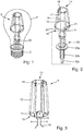
- Fig. 1 shows a schematic view of an embodiment of a lighting device according to the present invention.
- An enlarged view of the light engine is shown in Fig. 2 .
- the lighting device in this case a retrofit lamp (hereinafter referred to simply as "lamp"), suitable for replacing known incandescent lamps) comprises a glass bulb 1, a light engine 5 arranged inside the bulb 1, and a lamp base 2 with an Edison type screw base.
- the bulb can be filled with a gas having high thermal conductivity.
- the gas contains helium and/or hydrogen.
- the light engine comprises a holder having a first holding structure 14 and a second holding structure 15. Both holding structures are made from a wire (e.g. nickel plated stainless steel with a diameter between approximately 0.8 mm to approximately 2.5 mm) by bending the wire into the shape of the holding structure.
- the first holding structure 14 comprises an annular attachment section 17 which is attached to its connection section 9 via a radial section 18.
- the attachment section 17 is arranged essentially perpendicular to the straight connection section 9.
- the radial section 18 lies essentially in the plane of the attachment section 17.
- the lower end of the connection section 9 is fixedly held by a glass stem 33.
- the stem 33 comprises a flange 33a, two lead wires 33b and a glass tube 33c.
- the bulb 2 can be evacuated and filled with a gas having high thermal conductivity through the tube 33c which is then closed by melting.
- the second holding structure 15 comprises an annular attachment section 20 which is attached to its connection section 9 via a radial section 21.
- the attachment section 20 is arranged essentially perpendicular to the straight connection section 9.
- the radial section 21 lies essentially in the plane of the attachment section 20.
- the lower end of the connection section 9 is fixedly held by a glass stem 33.
- both holding structures 14,15 are made by bending a single wire, their production can easily be integrated into an automated production line. No soldering or welding is necessary for the production of the holding structures.
- the completed holder is strong enough to support the LED filaments.
- the LED filaments 12 are electrically conductively attached with their electrical contacts 13 to the attachment sections 17,20 of both holding structures 14,15, e.g. by soldering or welding.
- the LED filaments are connected in parallel such that the LED filaments work independently from each other. Accordingly, even if one of the LED filaments should fail, the lamp is still able to operate, thus prolonging the life of the lamp.
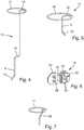
- Fig. 3 shows a schematic view of another embodiment of a light engine according to the present invention. Details of this embodiment are shown in Figs. 4-7 .
- the holder of the light engine shown in Fig. 3 comprises a first holding structure 14 and a second holding structure 15. Both holding structures are made from a wire (e.g. nickel plated stainless steel with a diameter between approximately 0.8 mm to approximately 2.5 mm) by bending the wire into the shape of the holding structure.
- a bridge 16 is attached to both holding structures 14,15 and stabilizes the holder.
- the first holding structure 14 comprises an annular attachment section 17 which is attached to its connection section 9 via a radial section 18.
- the attachment section 17 is arranged essentially perpendicular to the straight upper portion of the connection section 9.
- the radial section 18 lies essentially in the plane of the attachment section 17.
- connection section 9 includes a zig-zag bend 19, i.e. two bends of approximately 90°.
- the two bends of the zig-zag bend 19 are arranged such that the upper portion of connection section 9 and the lower portion of connection section 9 are essentially parallel to each other.
- the upper portion of connection section 9, the lower portion of connection section 9, and the zig-zag bend 19 essentially lie in the same plane.
- the end of the lower portion of connection section 9 is bent by an angle of approximately 45°, thus resulting in a fixation element 10 which serves for attaching the light engine 5 to connectors held for example by a glass stem.
- the second holding structure 15 comprises an annular attachment section 20 which is attached to its connection section 9 via a radial section 21.
- the attachment section 20 is arranged essentially perpendicular to the straight connection section 9.
- the radial section 21 lies essentially in the plane of the attachment section 20.
- the end of the lower portion of connection section 9 is bent by an angle of approximately 45°, thus resulting in a fixation element 10 which serves for attaching the light engine 5 to connectors held for example by a glass stem.
- the end of the wire runs parallel to a portion of the attachment section 17,20.
- the end of the wire can include a S-shaped bend next the point where the attachment section 17,20 meets the corresponding radial section 18,21 so that the end of the wire lies slightly below (alternatively above, inside, or outside) the attachment section 17,20.
- the end of the wire may be electrically conductively connected to the respective attachment section 17,20.
- the bridge 16 is shown in an unmounted state in Fig. 6 .
- the bridge 16 comprises a front portion 23 and a rear portion 22 connected to each other by a flexible hinge element 24.
- the rear portion 22 comprises two channels 25.
- the depth of the channels 25 is approximately equal to or greater than the thickness of the wire from which the holding structure 14,15 are made. Both channels 25 have an angle of approximately 90°.
- the zig-zag bend 19 of the first holding structure 14 and the 90° bend at the inner end of the radial portion 21 of the second holding structure 15 can be received by the channels 25.
- the front portion 23 of the bridge 16 can be moved over the rear portion 22 and can be fixed to the rear portion 22 by means of latches 26 on the front portion 23 engaging window 27 in the rear portion 22.
- bridge 16 is closed and fixates the two holding structures 14,15 with respect to each other.
- the bridge 16 is made from an electrically non-conductive plastic material (e.g. by injection molding), isolating the two holding structures 14,15 from each other. Since the part of the zig-zag bend 19 of the first holding structure and the 90° bend of the second holding structure are covered by the bridge 16, rotation of the bridge 15 with respect to either holding structure 14,15 is prevented.
- Fig. 7 shows schematically another embodiment of an upper portion of the first holding structure 14.
- An upper portion of the second holding structure 15 could also be designed in this alternative form.
- the radial section 28 does not lie in the plane of the attachment section 17, but rather at an angle to the plane downwards and inwards.
- the end of the wire does not run along the attachment section 17 (as shown in Fig. 6 ) but along the radial section 28.
- the end of the wire may be electrically conductively connected to the radial section 28.
- the above holding structures have been described as being bent from a single wire.
- a first wire section can be bent into a circle (attachment section) and a second wire portion can be bent into an L-shape (radial section and connection section). The end of one arm of the L can then be welded to the circle to obtain a holding structure as shown above in Figs. 1 and 2 .
- numerical valued may include the exact value as well as a usual tolerance interval, unless this is explicitly excluded.
Landscapes
- Engineering & Computer Science (AREA)
- Physics & Mathematics (AREA)
- Microelectronics & Electronic Packaging (AREA)
- Optics & Photonics (AREA)
- General Engineering & Computer Science (AREA)
- Fastening Of Light Sources Or Lamp Holders (AREA)
Claims (8)
- Beleuchtungsvorrichtung, umfassend einen lichtdurchlässigen Kolben (1), einen Sockel (2) mit mindestens zwei elektrischen Kontakten und eine innerhalb des Kolbens angeordnete Light Engine (5), wobei die Light Engine vier oder mehr LED-Filamente (12) umfasst, die an einem Halter befestigt sind, wobei der Halter eine erste Haltestruktur (14) aufweist, die elektrisch leitfähig ist, und eine zweite Haltestruktur (15), die elektrisch leitfähig ist, wobei jedes LED-Filament (12) mit einem ersten Ende mit der ersten Haltestruktur (14) und mit einem zweiten Ende mit der zweiten Haltestruktur (15) verbunden ist, wobei die erste Haltestruktur (14) mit einem ersten elektrischen Kontakt des Sockels (2) verbunden ist und die zweite Haltestruktur (15) mit einem zweiten elektrischen Kontakt des Sockels (2) verbunden ist, wobei die erste Haltestruktur (14) und die zweite Haltestruktur (15) jeweils einen im Wesentlichen länglichen Verbindungsabschnitt (9, 9) und einen Befestigungsabschnitt (17, 20) im Wesentlichen senkrecht zum Verbindungsabschnitt (9, 9) umfassen, wobei der Befestigungsabschnitt (17) der ersten Haltestruktur (14) und der Befestigungsabschnitt (20) der zweiten Haltestruktur (15) einen kreisförmigen oder polygonalen Umfang aufweist, dadurch gekennzeichnet, dass jede der ersten Haltestruktur (14) und der zweiten Haltestruktur (15) aus einem einzigen Draht gebildet ist.
- Beleuchtungsvorrichtung nach einem der vorstehenden Ansprüche, wobei mindestens einer von dem Verbindungsabschnitt (9) der ersten Haltekonstruktion (14) und dem Verbindungsabschnitt (9) der zweiten Haltekonstruktion (15) die Form einer geraden Linie aufweist.
- Beleuchtungsvorrichtung nach einem der vorstehenden Ansprüche, wobei für mindestens eine von der ersten Haltekonstruktion (14) und der zweiten Haltekonstruktion (15) der Verbindungsabschnitt (9) mit dem jeweiligen Befestigungsabschnitt (17, 20) durch einen radialen Abschnitt (18, 21) verbunden ist.
- Beleuchtungsvorrichtung nach Anspruch 3, wobei der radiale Abschnitt (18, 21) im Wesentlichen in der Ebene des jeweiligen Befestigungsabschnitts (17, 20) liegt.
- Beleuchtungsvorrichtung nach Anspruch 3, wobei der radiale Abschnitt (18, 21) unter einem Winkel zur Ebene des jeweiligen Befestigungsabschnitts (17, 20) angeordnet ist.
- Beleuchtungsvorrichtung nach einem der vorstehenden Ansprüche, wobei der Halter ein Brückenelement (16) umfasst, das an der ersten Haltekonstruktion (14) und der zweiten Haltekonstruktion (15) befestigt ist, wobei das Brückenelement (16) nicht elektrisch leitfähig ist.
- Beleuchtungsvorrichtung nach Anspruch 6, wobei das Brückenelement (16) einen vorderen Abschnitt (23) und einen hinteren Abschnitt (22) umfasst, der mit dem vorderen Abschnitt (23) verbindbar ist, wobei mindestens einer von dem vorderen Abschnitt (23) und dem hinteren Abschnitt (22) Vertiefungen zur Aufnahme der ersten Haltekonstruktion (14) und der zweiten Haltekonstruktion (15) umfasst.
- Beleuchtungsvorrichtung nach einem der Ansprüche 6-7, wobei mindestens einer von dem Verbindungsabschnitt (9) der ersten Haltestruktur (14) und dem Verbindungsabschnitt (9) der zweiten Haltestruktur (15) einen Verdrehsicherungabschnitt zum Verhindern einer Drehung des Brückenelements (16) um die jeweilige Haltestruktur (14, 15) aufweist.
Applications Claiming Priority (2)
| Application Number | Priority Date | Filing Date | Title |
|---|---|---|---|
| DE102016117450.5A DE102016117450A1 (de) | 2016-09-16 | 2016-09-16 | Leuchtvorrichtung mit verbesserter Verbindung zur Stromzuführung |
| CN201610977226.6A CN107830422A (zh) | 2016-09-16 | 2016-11-07 | 具有改进led保持件的led照明装置 |
Publications (2)
| Publication Number | Publication Date |
|---|---|
| EP3296614A1 EP3296614A1 (de) | 2018-03-21 |
| EP3296614B1 true EP3296614B1 (de) | 2019-05-22 |
Family
ID=59887065
Family Applications (1)
| Application Number | Title | Priority Date | Filing Date |
|---|---|---|---|
| EP17191071.4A Active EP3296614B1 (de) | 2016-09-16 | 2017-09-14 | Led-beleuchtungsvorrichtung mit verbessertem led-halter |
Country Status (1)
| Country | Link |
|---|---|
| EP (1) | EP3296614B1 (de) |
Families Citing this family (1)
| Publication number | Priority date | Publication date | Assignee | Title |
|---|---|---|---|---|
| JP7857945B2 (ja) | 2021-01-05 | 2026-05-13 | シグニファイ ホールディング ビー ヴィ | Ledフィラメント相互接続リング |
Family Cites Families (11)
| Publication number | Priority date | Publication date | Assignee | Title |
|---|---|---|---|---|
| TW201037212A (en) * | 2009-04-02 | 2010-10-16 | Liquidleds Lighting Corp | LED light bulb |
| US20140268779A1 (en) * | 2013-03-15 | 2014-09-18 | Litetronics International, Inc. | Led light emitting device |
| TW201502425A (zh) * | 2013-07-08 | 2015-01-16 | Lediamond Opto Corp | Led燈條式燈座及具有該燈座之燈泡 |
| CN204005447U (zh) * | 2014-07-08 | 2014-12-10 | 浙江力胜电子科技有限公司 | 一种led灯丝带和用led灯丝带制作的led灯丝灯 |
| CN104534302A (zh) * | 2014-10-09 | 2015-04-22 | 杭州永昌玻璃机械有限公司 | 一种led灯 |
| CN104676322B (zh) * | 2015-01-20 | 2017-01-04 | 浙江凯耀照明股份有限公司 | 提高发光强度的led灯丝排列结构及led灯丝灯 |
| CN104763900B (zh) * | 2015-04-01 | 2017-12-05 | 深圳恺业管理咨询有限公司 | 模块化led灯 |
| CN104791627B (zh) * | 2015-04-21 | 2018-10-12 | 贵州光浦森光电有限公司 | 一种led灯丝灯的构建方法及led灯丝灯 |
| CN204611431U (zh) * | 2015-05-06 | 2015-09-02 | 四川华川工业有限公司 | 正多边形led灯丝灯泡 |
| CN204852983U (zh) * | 2015-05-28 | 2015-12-09 | 山东晶泰星光电科技有限公司 | 一种led灯芯及led灯泡 |
| CN205424484U (zh) * | 2016-03-24 | 2016-08-03 | 浙江锐迪生光电有限公司 | Led灯丝灯 |
-
2017
- 2017-09-14 EP EP17191071.4A patent/EP3296614B1/de active Active
Non-Patent Citations (1)
| Title |
|---|
| None * |
Also Published As
| Publication number | Publication date |
|---|---|
| EP3296614A1 (de) | 2018-03-21 |
Similar Documents
| Publication | Publication Date | Title |
|---|---|---|
| US10215343B2 (en) | LED lighting device having an improved LED holder | |
| CN107830422A (zh) | 具有改进led保持件的led照明装置 | |
| US10767816B1 (en) | Light bulb apparatus | |
| EP2122652B1 (de) | Hochdruckentladungslampe | |
| US6972514B2 (en) | Low-pressure mercury vapor discharge lamp with improved heat dissipation, and manufacturing method therefore | |
| EP3745013B1 (de) | Glühlampenmaschine | |
| EP3308071B1 (de) | Glühlampe mit festkörper-beleuchtungsvorrichtungen | |
| EP3296614A1 (de) | Led-beleuchtungsvorrichtung mit verbessertem led-halter | |
| EP2784801A1 (de) | Heizerlampe und Heizmodul | |
| JPH02181358A (ja) | 白熱電気ランプおよびその製造方法 | |
| US20180204715A1 (en) | Adapter for replaceable lamp | |
| JP2006237007A (ja) | ハロゲンランプおよびハロゲンランプを提供する方法 | |
| EP3608581B1 (de) | Befestigungselement für led-filamente und led-lampe mit einem befestigungselement | |
| JP4197496B2 (ja) | 電球型蛍光ランプ | |
| EP0465198A2 (de) | Scheinwerferlampe | |
| CN101359576A (zh) | 具有外灯泡和嵌入式灯的电灯及其制造方法 | |
| JP5058266B2 (ja) | 反転可能なランプ口金 | |
| EP0422936A2 (de) | Verbesserte Herstellung einer kompakten Reflektorlampe | |
| CN101390191A (zh) | 照明单元 | |
| US10476221B2 (en) | Power supply socket for halogen lamp, and halogen lamp | |
| JP6289133B2 (ja) | ソケット及びこれを用いた照明器具 | |
| US20070138929A1 (en) | Halogen incandescent lamp | |
| JP2006202668A (ja) | 蛍光ランプ、蛍光ランプ装置及び照明器具 | |
| KR20190010782A (ko) | 엘이디 전구 | |
| JP2009205927A (ja) | 片口金形ハロゲン電球および照明装置 |
Legal Events
| Date | Code | Title | Description |
|---|---|---|---|
| PUAI | Public reference made under article 153(3) epc to a published international application that has entered the european phase |
Free format text: ORIGINAL CODE: 0009012 |
|
| STAA | Information on the status of an ep patent application or granted ep patent |
Free format text: STATUS: THE APPLICATION HAS BEEN PUBLISHED |
|
| AK | Designated contracting states |
Kind code of ref document: A1 Designated state(s): AL AT BE BG CH CY CZ DE DK EE ES FI FR GB GR HR HU IE IS IT LI LT LU LV MC MK MT NL NO PL PT RO RS SE SI SK SM TR |
|
| AX | Request for extension of the european patent |
Extension state: BA ME |
|
| RIN1 | Information on inventor provided before grant (corrected) |
Inventor name: FRYE, LAMBERT Inventor name: HABERKORN, LENE Inventor name: XIE, QIAN Inventor name: LI, LIQIN Inventor name: ECKERT, KLAUS Inventor name: YU, HUALI Inventor name: LIU, JITAO Inventor name: XU, BAIJIN |
|
| STAA | Information on the status of an ep patent application or granted ep patent |
Free format text: STATUS: REQUEST FOR EXAMINATION WAS MADE |
|
| 17P | Request for examination filed |
Effective date: 20180920 |
|
| RBV | Designated contracting states (corrected) |
Designated state(s): AL AT BE BG CH CY CZ DE DK EE ES FI FR GB GR HR HU IE IS IT LI LT LU LV MC MK MT NL NO PL PT RO RS SE SI SK SM TR |
|
| RIC1 | Information provided on ipc code assigned before grant |
Ipc: F21Y 115/10 20160101ALN20181107BHEP Ipc: F21K 9/238 20160101ALI20181107BHEP Ipc: F21K 9/237 20160101ALI20181107BHEP Ipc: F21K 9/232 20160101AFI20181107BHEP |
|
| GRAP | Despatch of communication of intention to grant a patent |
Free format text: ORIGINAL CODE: EPIDOSNIGR1 |
|
| STAA | Information on the status of an ep patent application or granted ep patent |
Free format text: STATUS: GRANT OF PATENT IS INTENDED |
|
| INTG | Intention to grant announced |
Effective date: 20190104 |
|
| GRAS | Grant fee paid |
Free format text: ORIGINAL CODE: EPIDOSNIGR3 |
|
| GRAA | (expected) grant |
Free format text: ORIGINAL CODE: 0009210 |
|
| STAA | Information on the status of an ep patent application or granted ep patent |
Free format text: STATUS: THE PATENT HAS BEEN GRANTED |
|
| AK | Designated contracting states |
Kind code of ref document: B1 Designated state(s): AL AT BE BG CH CY CZ DE DK EE ES FI FR GB GR HR HU IE IS IT LI LT LU LV MC MK MT NL NO PL PT RO RS SE SI SK SM TR |
|
| REG | Reference to a national code |
Ref country code: GB Ref legal event code: FG4D |
|
| REG | Reference to a national code |
Ref country code: CH Ref legal event code: EP |
|
| REG | Reference to a national code |
Ref country code: IE Ref legal event code: FG4D |
|
| REG | Reference to a national code |
Ref country code: DE Ref legal event code: R096 Ref document number: 602017004107 Country of ref document: DE |
|
| REG | Reference to a national code |
Ref country code: AT Ref legal event code: REF Ref document number: 1136542 Country of ref document: AT Kind code of ref document: T Effective date: 20190615 |
|
| REG | Reference to a national code |
Ref country code: NL Ref legal event code: MP Effective date: 20190522 |
|
| REG | Reference to a national code |
Ref country code: LT Ref legal event code: MG4D |
|
| PG25 | Lapsed in a contracting state [announced via postgrant information from national office to epo] |
Ref country code: FI Free format text: LAPSE BECAUSE OF FAILURE TO SUBMIT A TRANSLATION OF THE DESCRIPTION OR TO PAY THE FEE WITHIN THE PRESCRIBED TIME-LIMIT Effective date: 20190522 Ref country code: NO Free format text: LAPSE BECAUSE OF FAILURE TO SUBMIT A TRANSLATION OF THE DESCRIPTION OR TO PAY THE FEE WITHIN THE PRESCRIBED TIME-LIMIT Effective date: 20190822 Ref country code: LT Free format text: LAPSE BECAUSE OF FAILURE TO SUBMIT A TRANSLATION OF THE DESCRIPTION OR TO PAY THE FEE WITHIN THE PRESCRIBED TIME-LIMIT Effective date: 20190522 Ref country code: NL Free format text: LAPSE BECAUSE OF FAILURE TO SUBMIT A TRANSLATION OF THE DESCRIPTION OR TO PAY THE FEE WITHIN THE PRESCRIBED TIME-LIMIT Effective date: 20190522 Ref country code: PT Free format text: LAPSE BECAUSE OF FAILURE TO SUBMIT A TRANSLATION OF THE DESCRIPTION OR TO PAY THE FEE WITHIN THE PRESCRIBED TIME-LIMIT Effective date: 20190922 Ref country code: ES Free format text: LAPSE BECAUSE OF FAILURE TO SUBMIT A TRANSLATION OF THE DESCRIPTION OR TO PAY THE FEE WITHIN THE PRESCRIBED TIME-LIMIT Effective date: 20190522 Ref country code: HR Free format text: LAPSE BECAUSE OF FAILURE TO SUBMIT A TRANSLATION OF THE DESCRIPTION OR TO PAY THE FEE WITHIN THE PRESCRIBED TIME-LIMIT Effective date: 20190522 Ref country code: SE Free format text: LAPSE BECAUSE OF FAILURE TO SUBMIT A TRANSLATION OF THE DESCRIPTION OR TO PAY THE FEE WITHIN THE PRESCRIBED TIME-LIMIT Effective date: 20190522 Ref country code: AL Free format text: LAPSE BECAUSE OF FAILURE TO SUBMIT A TRANSLATION OF THE DESCRIPTION OR TO PAY THE FEE WITHIN THE PRESCRIBED TIME-LIMIT Effective date: 20190522 |
|
| PG25 | Lapsed in a contracting state [announced via postgrant information from national office to epo] |
Ref country code: LV Free format text: LAPSE BECAUSE OF FAILURE TO SUBMIT A TRANSLATION OF THE DESCRIPTION OR TO PAY THE FEE WITHIN THE PRESCRIBED TIME-LIMIT Effective date: 20190522 Ref country code: GR Free format text: LAPSE BECAUSE OF FAILURE TO SUBMIT A TRANSLATION OF THE DESCRIPTION OR TO PAY THE FEE WITHIN THE PRESCRIBED TIME-LIMIT Effective date: 20190823 Ref country code: RS Free format text: LAPSE BECAUSE OF FAILURE TO SUBMIT A TRANSLATION OF THE DESCRIPTION OR TO PAY THE FEE WITHIN THE PRESCRIBED TIME-LIMIT Effective date: 20190522 Ref country code: BG Free format text: LAPSE BECAUSE OF FAILURE TO SUBMIT A TRANSLATION OF THE DESCRIPTION OR TO PAY THE FEE WITHIN THE PRESCRIBED TIME-LIMIT Effective date: 20190822 |
|
| REG | Reference to a national code |
Ref country code: AT Ref legal event code: MK05 Ref document number: 1136542 Country of ref document: AT Kind code of ref document: T Effective date: 20190522 |
|
| PG25 | Lapsed in a contracting state [announced via postgrant information from national office to epo] |
Ref country code: CZ Free format text: LAPSE BECAUSE OF FAILURE TO SUBMIT A TRANSLATION OF THE DESCRIPTION OR TO PAY THE FEE WITHIN THE PRESCRIBED TIME-LIMIT Effective date: 20190522 Ref country code: RO Free format text: LAPSE BECAUSE OF FAILURE TO SUBMIT A TRANSLATION OF THE DESCRIPTION OR TO PAY THE FEE WITHIN THE PRESCRIBED TIME-LIMIT Effective date: 20190522 Ref country code: SK Free format text: LAPSE BECAUSE OF FAILURE TO SUBMIT A TRANSLATION OF THE DESCRIPTION OR TO PAY THE FEE WITHIN THE PRESCRIBED TIME-LIMIT Effective date: 20190522 Ref country code: AT Free format text: LAPSE BECAUSE OF FAILURE TO SUBMIT A TRANSLATION OF THE DESCRIPTION OR TO PAY THE FEE WITHIN THE PRESCRIBED TIME-LIMIT Effective date: 20190522 Ref country code: EE Free format text: LAPSE BECAUSE OF FAILURE TO SUBMIT A TRANSLATION OF THE DESCRIPTION OR TO PAY THE FEE WITHIN THE PRESCRIBED TIME-LIMIT Effective date: 20190522 Ref country code: DK Free format text: LAPSE BECAUSE OF FAILURE TO SUBMIT A TRANSLATION OF THE DESCRIPTION OR TO PAY THE FEE WITHIN THE PRESCRIBED TIME-LIMIT Effective date: 20190522 |
|
| REG | Reference to a national code |
Ref country code: DE Ref legal event code: R097 Ref document number: 602017004107 Country of ref document: DE |
|
| PG25 | Lapsed in a contracting state [announced via postgrant information from national office to epo] |
Ref country code: SM Free format text: LAPSE BECAUSE OF FAILURE TO SUBMIT A TRANSLATION OF THE DESCRIPTION OR TO PAY THE FEE WITHIN THE PRESCRIBED TIME-LIMIT Effective date: 20190522 Ref country code: IT Free format text: LAPSE BECAUSE OF FAILURE TO SUBMIT A TRANSLATION OF THE DESCRIPTION OR TO PAY THE FEE WITHIN THE PRESCRIBED TIME-LIMIT Effective date: 20190522 |
|
| PLBE | No opposition filed within time limit |
Free format text: ORIGINAL CODE: 0009261 |
|
| STAA | Information on the status of an ep patent application or granted ep patent |
Free format text: STATUS: NO OPPOSITION FILED WITHIN TIME LIMIT |
|
| PG25 | Lapsed in a contracting state [announced via postgrant information from national office to epo] |
Ref country code: TR Free format text: LAPSE BECAUSE OF FAILURE TO SUBMIT A TRANSLATION OF THE DESCRIPTION OR TO PAY THE FEE WITHIN THE PRESCRIBED TIME-LIMIT Effective date: 20190522 |
|
| 26N | No opposition filed |
Effective date: 20200225 |
|
| PG25 | Lapsed in a contracting state [announced via postgrant information from national office to epo] |
Ref country code: PL Free format text: LAPSE BECAUSE OF FAILURE TO SUBMIT A TRANSLATION OF THE DESCRIPTION OR TO PAY THE FEE WITHIN THE PRESCRIBED TIME-LIMIT Effective date: 20190522 |
|
| PG25 | Lapsed in a contracting state [announced via postgrant information from national office to epo] |
Ref country code: MC Free format text: LAPSE BECAUSE OF FAILURE TO SUBMIT A TRANSLATION OF THE DESCRIPTION OR TO PAY THE FEE WITHIN THE PRESCRIBED TIME-LIMIT Effective date: 20190522 Ref country code: SI Free format text: LAPSE BECAUSE OF FAILURE TO SUBMIT A TRANSLATION OF THE DESCRIPTION OR TO PAY THE FEE WITHIN THE PRESCRIBED TIME-LIMIT Effective date: 20190522 |
|
| PG25 | Lapsed in a contracting state [announced via postgrant information from national office to epo] |
Ref country code: IE Free format text: LAPSE BECAUSE OF NON-PAYMENT OF DUE FEES Effective date: 20190914 Ref country code: LU Free format text: LAPSE BECAUSE OF NON-PAYMENT OF DUE FEES Effective date: 20190914 |
|
| REG | Reference to a national code |
Ref country code: BE Ref legal event code: MM Effective date: 20190930 |
|
| PG25 | Lapsed in a contracting state [announced via postgrant information from national office to epo] |
Ref country code: BE Free format text: LAPSE BECAUSE OF NON-PAYMENT OF DUE FEES Effective date: 20190930 |
|
| PG25 | Lapsed in a contracting state [announced via postgrant information from national office to epo] |
Ref country code: FR Free format text: LAPSE BECAUSE OF NON-PAYMENT OF DUE FEES Effective date: 20190930 |
|
| REG | Reference to a national code |
Ref country code: CH Ref legal event code: PL |
|
| PG25 | Lapsed in a contracting state [announced via postgrant information from national office to epo] |
Ref country code: CY Free format text: LAPSE BECAUSE OF FAILURE TO SUBMIT A TRANSLATION OF THE DESCRIPTION OR TO PAY THE FEE WITHIN THE PRESCRIBED TIME-LIMIT Effective date: 20190522 |
|
| PG25 | Lapsed in a contracting state [announced via postgrant information from national office to epo] |
Ref country code: IS Free format text: LAPSE BECAUSE OF FAILURE TO SUBMIT A TRANSLATION OF THE DESCRIPTION OR TO PAY THE FEE WITHIN THE PRESCRIBED TIME-LIMIT Effective date: 20190922 |
|
| PG25 | Lapsed in a contracting state [announced via postgrant information from national office to epo] |
Ref country code: MT Free format text: LAPSE BECAUSE OF FAILURE TO SUBMIT A TRANSLATION OF THE DESCRIPTION OR TO PAY THE FEE WITHIN THE PRESCRIBED TIME-LIMIT Effective date: 20190522 Ref country code: HU Free format text: LAPSE BECAUSE OF FAILURE TO SUBMIT A TRANSLATION OF THE DESCRIPTION OR TO PAY THE FEE WITHIN THE PRESCRIBED TIME-LIMIT; INVALID AB INITIO Effective date: 20170914 |
|
| PG25 | Lapsed in a contracting state [announced via postgrant information from national office to epo] |
Ref country code: CH Free format text: LAPSE BECAUSE OF NON-PAYMENT OF DUE FEES Effective date: 20200930 Ref country code: LI Free format text: LAPSE BECAUSE OF NON-PAYMENT OF DUE FEES Effective date: 20200930 |
|
| GBPC | Gb: european patent ceased through non-payment of renewal fee |
Effective date: 20210914 |
|
| PG25 | Lapsed in a contracting state [announced via postgrant information from national office to epo] |
Ref country code: MK Free format text: LAPSE BECAUSE OF FAILURE TO SUBMIT A TRANSLATION OF THE DESCRIPTION OR TO PAY THE FEE WITHIN THE PRESCRIBED TIME-LIMIT Effective date: 20190522 |
|
| PG25 | Lapsed in a contracting state [announced via postgrant information from national office to epo] |
Ref country code: GB Free format text: LAPSE BECAUSE OF NON-PAYMENT OF DUE FEES Effective date: 20210914 |
|
| PGFP | Annual fee paid to national office [announced via postgrant information from national office to epo] |
Ref country code: DE Payment date: 20250926 Year of fee payment: 9 |