EP3296616B1 - Dispositif d'éclairage de source de lumière de surface - Google Patents
Dispositif d'éclairage de source de lumière de surface Download PDFInfo
- Publication number
- EP3296616B1 EP3296616B1 EP16796064.0A EP16796064A EP3296616B1 EP 3296616 B1 EP3296616 B1 EP 3296616B1 EP 16796064 A EP16796064 A EP 16796064A EP 3296616 B1 EP3296616 B1 EP 3296616B1
- Authority
- EP
- European Patent Office
- Prior art keywords
- light
- light guide
- guide plate
- light source
- reflection surface
- Prior art date
- Legal status (The legal status is an assumption and is not a legal conclusion. Google has not performed a legal analysis and makes no representation as to the accuracy of the status listed.)
- Active
Links
Images





Classifications
-
- G—PHYSICS
- G02—OPTICS
- G02B—OPTICAL ELEMENTS, SYSTEMS OR APPARATUS
- G02B6/00—Light guides; Structural details of arrangements comprising light guides and other optical elements, e.g. couplings
- G02B6/0001—Light guides; Structural details of arrangements comprising light guides and other optical elements, e.g. couplings specially adapted for lighting devices or systems
- G02B6/0011—Light guides; Structural details of arrangements comprising light guides and other optical elements, e.g. couplings specially adapted for lighting devices or systems the light guides being planar or of plate-like form
- G02B6/0033—Means for improving the coupling-out of light from the light guide
- G02B6/0035—Means for improving the coupling-out of light from the light guide provided on the surface of the light guide or in the bulk of it
- G02B6/0038—Linear indentations or grooves, e.g. arc-shaped grooves or meandering grooves, extending over the full length or width of the light guide
-
- F—MECHANICAL ENGINEERING; LIGHTING; HEATING; WEAPONS; BLASTING
- F21—LIGHTING
- F21S—NON-PORTABLE LIGHTING DEVICES; SYSTEMS THEREOF; VEHICLE LIGHTING DEVICES SPECIALLY ADAPTED FOR VEHICLE EXTERIORS
- F21S2/00—Systems of lighting devices, not provided for in main groups F21S4/00 - F21S10/00 or F21S19/00, e.g. of modular construction
-
- G—PHYSICS
- G02—OPTICS
- G02B—OPTICAL ELEMENTS, SYSTEMS OR APPARATUS
- G02B6/00—Light guides; Structural details of arrangements comprising light guides and other optical elements, e.g. couplings
- G02B6/0001—Light guides; Structural details of arrangements comprising light guides and other optical elements, e.g. couplings specially adapted for lighting devices or systems
- G02B6/0011—Light guides; Structural details of arrangements comprising light guides and other optical elements, e.g. couplings specially adapted for lighting devices or systems the light guides being planar or of plate-like form
- G02B6/0013—Means for improving the coupling-in of light from the light source into the light guide
- G02B6/0023—Means for improving the coupling-in of light from the light source into the light guide provided by one optical element, or plurality thereof, placed between the light guide and the light source, or around the light source
- G02B6/003—Lens or lenticular sheet or layer
-
- G—PHYSICS
- G02—OPTICS
- G02B—OPTICAL ELEMENTS, SYSTEMS OR APPARATUS
- G02B6/00—Light guides; Structural details of arrangements comprising light guides and other optical elements, e.g. couplings
- G02B6/0001—Light guides; Structural details of arrangements comprising light guides and other optical elements, e.g. couplings specially adapted for lighting devices or systems
- G02B6/0011—Light guides; Structural details of arrangements comprising light guides and other optical elements, e.g. couplings specially adapted for lighting devices or systems the light guides being planar or of plate-like form
- G02B6/0033—Means for improving the coupling-out of light from the light guide
- G02B6/005—Means for improving the coupling-out of light from the light guide provided by one optical element, or plurality thereof, placed on the light output side of the light guide
-
- G—PHYSICS
- G02—OPTICS
- G02B—OPTICAL ELEMENTS, SYSTEMS OR APPARATUS
- G02B6/00—Light guides; Structural details of arrangements comprising light guides and other optical elements, e.g. couplings
- G02B6/0001—Light guides; Structural details of arrangements comprising light guides and other optical elements, e.g. couplings specially adapted for lighting devices or systems
- G02B6/0011—Light guides; Structural details of arrangements comprising light guides and other optical elements, e.g. couplings specially adapted for lighting devices or systems the light guides being planar or of plate-like form
- G02B6/0033—Means for improving the coupling-out of light from the light guide
- G02B6/005—Means for improving the coupling-out of light from the light guide provided by one optical element, or plurality thereof, placed on the light output side of the light guide
- G02B6/0055—Reflecting element, sheet or layer
Definitions
- the present disclosure relates to a surface light source lighting device for a backlight source which is mainly used in on-vehicle liquid crystal displays or signage for outdoor and indoor exhibitions.
- a surface light source lighting device reflecting the preamble of present claim 1 is disclosed by the document US 2009/284985 .
- a backlight source using a light emitting diode (hereinafter, referred to as an "LED") has been recently widely used since the backlight source is greatly advantageous in terms of being thinner, more lightweight, and having higher efficiency than a light source using a cold cathode tube.
- LED light emitting diode
- an edge light type is frequently used in which a light guide plate as a thin acryl plate or a polycarbonate plate having a rear surface on which minute patterns are formed is used, and light is emitted from a front surface of the light guide plate, that is, surface light emission occurs by causing light incident to an edge surface of the light guide plate.
- the edge light type it is considered important that light radiated from a light source such as an LED chip is incident to the light guide plate, the light is controlled to be distributed in a desired direction, and thus light is uniformly emitted without causing a bright line or unevenness such as non-uniformity on the light guide plate. For this, if light is caused to be uniformly incident to the light guide plate, and a pattern of the light guide plate is appropriately disposed, light can be controlled to be distributed as desired without generating luminance unevenness or a dark line.
- FIGS. 9A and 9B illustrate a configuration of a surface light source lighting device of the related art.
- the surface light source lighting device of the related art as illustrated in FIG. 9A , light from LEDs 32 is guided into light guide plate 34 from incidence edge surface 35 via light incidence lens 33, and the light travels to an opposite side while being reflected at planar portion 36 of a rear surface of light guide plate 34 as illustrated in FIG. 9B .
- Light guide patterns 37 are formed on planar portion 36.
- Light guide plate 34 is made of a resin material such as acryl or polycarbonate, and thus causes total reflection at an incidence angle of about 41° or more due to a difference in a refractive index from air.
- Light reaches light guide pattern 37 in the middle of being guided inside light guide plate 34, the light is reflected toward a front surface of light guide plate 34 from light guide pattern 37, and thus light is emitted from that portion.
- Such light guide patterns 37 are formed on the entire rear surface of light guide plate 34 with a specific pitch, and thus reflection occurs toward the front surface of light guide plate 34 at each location so that light is emitted from the entire front surface of light guide plate 34.
- Light from LED 32 is generally radially generated.
- the light is incident to light guide plate 34 and reaches light guide pattern 37, the light is obliquely reflected toward the front surface of light guide plate 34 from light guide pattern 37 or obliquely reflected toward the rear surface of light guide plate 34 instead of being reflected toward the front surface of light guide plate 34, depending on an incidence angle, and thus light radiated from the surface light source lighting device is spread.
- light incidence lens 33 which is designed to form substantially parallel light is inserted before light guide plate 34, and thus light close to parallel light is incident to light guide plate 34.
- Light incidence lens 33 is also formed in a plate shape by using a light transmissive material such as acryl or polycarbonate, and a plurality of light incidence lenses are arranged in parallel so as to form light incidence lens array 38.
- Light radiated from LEDs 32 is transmitted through respective light incidence lenses 33 so as to be converted into substantially parallel light, and is then incident to light guide plate 34 from incidence edge surface 35. Consequently, an amount of light which obliquely reaches light guide patterns 37 is reduced, and thus it is possible to control a direction of light toward the front surface of light guide plate 34.
- a direction of light is required to be controlled not only in the front direction but also in a specific direction according to a use application thereof.
- a display used instead of an analog display such as a speedometer if light is emitted in an upper front direction, the light is reflected at a front window and enters a visual field. Therefore, a light blocking hood is necessary, and this lowers design nature.
- it is preferable that light is not emitted in an upper front direction, and is emitted in a lower front direction.
- a surface light source lighting device for outdoor or indoor exhibition digital signage in a case where the lighting device is provided at a high position, it is required for luminance to be high in a lower front direction so that the lighting device is easily visible rather than to be high in a front direction.
- FIGS. 9A and 9B there is a form in which light incidence lens 33 is inserted between LEDs 32 and light guide plate 34, and thus a distance increases by the width thereof. Consequently, a width of a bezel as a frame of a liquid crystal monitor or display increases, and thus the design nature is lowered, and the liquid crystal monitor or the display may not be mounted in a vehicle in a vehicular application due to the restriction in the size.
- the object of the present invention is to provide a surface light source lighting device which can control a light emission direction in a specific direction, required in an on-vehicle display or the like as defined in claim 1.
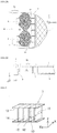
- FIGS. 1A, 1B and 1C illustrate a surface light source lighting device of the present disclosure.
- FIG. 1A is a front view of the surface light source lighting device of the present disclosure
- FIG. 1B is a bottom view of the surface light source lighting device
- FIG. 1C is a rear view of the surface light source lighting device.
- the surface light source lighting device includes, as illustrated in FIG. 1A , plate-shaped light guide plate 1; light source 2a disposed on left edge surface 1L side of the light guide plate; light source 2b disposed on right edge surface 1R side of light guide plate 1; light incidence portion 3a interposed between light source 2a and edge surface 1L of light guide plate 1; and light incidence portion 3b interposed between light source 2b and edge surface 1R of light guide plate 1.
- X indicates a horizontal direction of light guide plate 1
- Y indicates a vertical direction of light guide plate
- Z indicates a direction directed from a rear surface of light guide plate 1 toward a front surface thereof.
- first light guide patterns 4A and second light guide patterns 4B formed of linear groove groups are formed on the rear surface of light guide plate 1.
- Each of first light guide patterns 4A and second light guide patterns 4B is a groove-shaped recess and is formed in a triangular edge shape on the rear surface of light guide plate 1.
- Each of first light guide patterns 4A formed with a constant pitch is inclined by ⁇ 1 so that the other end thereof comes close to edge surface 1R of light guide plate 1 with an upper side or edge surface 1L of light guide plate 1 as one end thereof in FIG. 1A .
- Each of second light guide patterns 4B formed with a constant pitch is inclined by ⁇ 2 so that the other end thereof comes close to edge surface 1L of light guide plate 1 with the upper side or edge surface 1R of light guide plate 1 as one end thereof in FIG. 1A .
- Light generated by light source 2a and light source 2b passes through light incidence portion 3a and light incidence portion 3b so as to be incident to light guide plate 1, and thus the light is emitted from the front surface of light guide plate 1, that is, surface light emission occurs. Therefore, light guide plate 1 functions as a part of a backlight of, for example, an on-vehicle display.
- rear surface sheet 5 is disposed on the rear surface of light guide plate 1.
- a light absorbing material is used for rear surface sheet 5 which restricts unnecessary light leaking to the rear surface of light guide plate 1 from returning to the front surface side of light guide plate 1.
- FIG. 1C does not illustrate rear surface sheet 5 in order to illustrate first light guide patterns 4A and second light guide patterns 4B.
- each of light source 2a and light source 2b is formed of LED mounting board 9 on which a plurality of LEDs 8 are serially arranged.
- Each of light incidence portion 3a and light incidence portion 3b is formed of light incidence lens 6 and louver 7.
- light emitted from LEDs 8 is incident to light incidence lens 6.
- Curved shapes are formed on both of an LED side and a light guide plate side of light incidence lens 6.
- Light incidence lens 6 is formed in a so-called meniscus shape so that curved surface 10 on the LED side has a concave shape, and curved surface 11 on the light guide plate side has a convex shape.
- Curved surface 10 on the LED side having a concave shape has a function of causing light passing therethrough to be refracted and thus to be diffused in a wider manner than a radiation angle of the LED.
- the light is refracted by curved surface 11 on the light guide plate side having a convex shape so as to be incident to light guide plate 1 as substantially parallel light. Since light is spread and then is converted into substantially parallel light by using both surfaces of light incidence lens 6, it is possible to reduce unevenness of light and also to reduce a length in an optical axis direction of light incidence lens 6 from LEDs 8 to light guide plate 1.
- a length in an optical axis direction from LEDs 8 to light guide plate 1 is equal to or more than a pitch of LEDs 8, but, in the lens of the present embodiment, the length can be made smaller than a distance of the pitch of LEDs 8. If the length is equal to or more than the pitch of the LEDs, a size thereof increases, and, thus, in a case of a vehicular application, the lens is hardly employed due to a large mounting volume being taken.
- the pitch of LEDs 8 is 6 mm
- the length in the optical axis direction to light guide plate 1 can be realized to be 5 mm or less. In other words, the length of light incidence lens 6 in the optical axis direction to light guide plate 1 is smaller than the pitch of LEDs 8.
- louver 7 is provided between light incidence lens 6 and light guide plate 1. Unnecessary light which is obliquely deviated is absorbed by louver 7, and thus only light beams which are arranged to be substantially parallel are incident to light guide plate 1.
- FIG. 3 illustrates louver 7.
- Louver 7 has partition walls 12 which are disposed in a direction orthogonal to the front surface and the rear surface of light guide plate 1 with an interval in a longitudinal direction (Y direction) of light guide plate 1; front reflection surface 13 which closes edge surfaces of partition walls 12 on the front surface side; and rear reflection surface 14 which closes edge surfaces of partition walls 12 on the rear surface side.
- the inside of a region surrounded by two partition walls 12 and 12, front reflection surface 13, and rear reflection surface 14 is formed as an air layer or a resin layer. In a case of the air layer, front reflection surface 13 and rear reflection surface 14 cause mirror-surface reflection, and in a case where the inside of the region is filled with the resin layer, reflection occurs at an interface of a resin.
- a black absorption material such as carbon is used for partition wall 12 which thus has a function of absorbing light when the light is incident thereto without reflecting the light. If louver width 16 is restricted relative to louver depth 15, light which has a large incidence angle in the surface of light guide plate 1 in the optical axis direction from LEDs 8 to light guide plate 1 is absorbed by partition walls 12. Therefore, only light which travels straight is output from louver 7, and can thus be controlled to enter light guide plate 1 as substantially parallel light.
- a ratio of louver width 16 to louver depth 15 is 0.1 to 0.6. If the ratio is more than 0.6, an incidence angle exceeds 31°, and thus a direction of light cannot be controlled. If the ratio is less than 0.1, light is almost absorbed, and thus a necessary amount of light cannot be obtained. As an example, in a case where louver depth 15 is 1 mm, and louver width 16 is 0.5 mm, the ratio therebetween is 0.5.
- first light guide patterns 4A and second light guide patterns 4B formed on the rear surface of light guide plate 1 is reflected toward the front surface side of light guide plate 1 through reflection.
- first light guide patterns 4A and second light guide patterns 4B are characterized in that the patterns are disposed to be inclined in oblique directions with respect to an incidence direction of light to light guide plate 1.
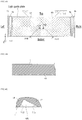
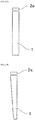
- FIG. 4B is a sectional view of first light guide patterns 4A taken along the line IVB-IVB in FIG. 4A .
- the light guide pattern angle ⁇ 1 of first light guide pattern 4A is set to an angle of 20° to 50° in a case where an incidence direction from light source 2a to light guide plate 1 is set to be 0°.
- ⁇ 1 is set to 45°.
- FIG. 4C is an enlarged view of the first light guide pattern illustrated in FIG. 4B .
- First light guide pattern 4A is formed of principal prism reflection surface 17 having a base angle of ⁇ A1, and subsidiary prism reflection surface 18 having a base angle of ⁇ A2.
- FIG. 4D is a sectional view of second light guide patterns 4B taken along the line IVD-IVD in FIG. 4A .
- Light guide pattern angle ⁇ 2 of second light guide pattern 4B is set to an angle of 20° to 50° in a case where an incidence direction from light source 2b to light guide plate 1 is set to be 0°.
- ⁇ 2 is set to 45°.
- FIG. 4E is an enlarged view of the second light guide pattern illustrated in FIG. 4D .
- Second light guide pattern 4B is formed of principal prism reflection surface 19 having a base angle of ⁇ B1, and subsidiary prism reflection surface 20 having a base angle of ⁇ B2.
- light guide pattern angles ⁇ 1 and ⁇ 2 are less than 20°, light from light sources 2a and 2b scarcely arrives, and a necessary amount of light cannot be obtained. In a case where light guide pattern angles ⁇ 1 and ⁇ 2 are more than 50°, a distribution direction of light emitted from the front surface of light guide plate 1 in a lower direction cannot be controlled.
- Some of light which is emitted from light source 2a and is incident to the inside of light guide plate 1 from left edge surface 1L of light guide plate 1 is reflected at an interface on the front surface side of light guide plate 1 or an interface on the rear surface side so as to propagate through light guide plate 1.
- the light is reflected at principal prism reflection surface 19 of second light guide pattern 4B, and is further reflected at the interface on the front surface side of light guide plate 1 so as to propagate through light guide plate 1.
- the light is reflected at subsidiary prism reflection surface 18 of first light guide pattern 4A so as to be emitted toward the front surface side of light guide plate 1.
- Some of light which is emitted from light source 2b and is incident to the inside of light guide plate 1 from right edge surface 1R of light guide plate 1 is reflected at the interface on the front surface side of light guide plate 1 or the interface on the rear surface side so as to propagate through light guide plate 1.
- the light is reflected at principal prism reflection surface 17 of first light guide pattern 4A, and is further reflected at the interface on the front surface side of light guide plate 1 so as to propagate through light guide plate 1.
- the light is reflected at subsidiary prism reflection surface 20 of second light guide pattern 4B so as to be emitted toward the front surface side of light guide plate 1.
- Subsidiary prism reflection surfaces 18 and 20 achieve an effect of reversing a direction of light in the lower direction when light first reaches the surfaces.
- Base angle ⁇ A1 and ⁇ B1 of principal prism reflection surfaces 17 and 19 are set to an angle of at least 30° to at most 50°. In a case where the base angle is less than 30°, light leakage occurs from the front surface of light guide plate 1 in the upper direction, and thus luminance is reduced. In a case where the base angle is more than 50°, light cannot be reflected from the front surface of light guide plate 1 in the obliquely lower direction, and thus leaks almost directly below.
- Base angle ⁇ A2 and ⁇ B2 of subsidiary prism reflection surface 18 and 20 are set to an angle of at least 70° to at most 90°. In a case where the base angle is less than 70°, light leakage occurs from the front surface of light guide plate 1 in the upper direction, and thus luminance is reduced. In a case where the base angle is more than 90°, an inclined surface has an overhung form, and this cannot be processed.
- ⁇ A1 of principal prism reflection surface 17 is set to 32°
- ⁇ A2 of subsidiary prism reflection surface 18 is set to 72°.
- second light guide pattern 4B light is mainly reflected at principal prism reflection surface 19, and angle ⁇ B1 of the surface greatly contributes to direction control.
- Inclined angle ⁇ B1 of the principal prism reflection surface gives an effect of reversing a direction of light in the lower direction when light first reaches the surface.
- Base angle ⁇ B1 of principal prism reflection surface 19 is the same as base angle ⁇ A1 of principal prism reflection surface 17.
- Base angle ⁇ B2 of subsidiary prism reflection surface 20 is the same as base angle ⁇ A2 of subsidiary prism reflection surface 18.
- ⁇ B1 of principal prism reflection surface 19 is set to 32°
- ⁇ B2 of subsidiary prism reflection surface 20 is set to 72°.
- first light guide patterns 4A and second light guide patterns 4B having different inclinations are formed on light guide plate 1, regarding light which is incident to light guide plate 1 from left light source 2a, as illustrated in FIG. 5A , light beam 21 which is guided along the inside of light guide plate 1 reaches subsidiary prism reflection surface 18 so as to be reflected in the lower direction in the light guide plate, and is then reflected with an angle of the inclination of principal prism reflection surface 19 thereat. As illustrated in FIG. 5B , reflected light beam 21 is subjected to direction control so as to be emitted from the front surface of light guide plate 1 in the obliquely lower direction.
- light beam 21 which is guided along the inside of light guide plate 1 reaches subsidiary prism reflection surface 20 so as to be reflected in the lower direction in the light guide plate, and is then reflected with an angle of the inclination of principal prism reflection surface 17 thereat.
- Reflected light beam 21 is subjected to direction control so as to be emitted from the front surface of light guide plate 1 in the obliquely lower direction.
- FIG. 6 illustrates distribution 24 of light whose emission direction 23 can be controlled in the lower front direction by using first light guide patterns 4A and second light guide patterns 4B in the above-described way.
- Surface light source lighting device 22 integrates light guide plate 1, light source 2a, light source 2b, light incidence portion 3a, and light incidence portion 3b.
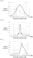
- FIG. 7A is a diagram illustrating vertical distribution characteristics of luminance in a surface light source lighting device of the related art as a comparative example.
- a transverse axis expresses an emission angle, in which 0° indicates the front side, -90° indicates a directly upper side, and +90° indicates a directly lower side.
- a longitudinal axis expresses a value relative to a peak value of luminance.
- the luminance is widely distributed in a state in which the front side of a light guide plate shows a peak, and light is also strongly emitted in the vertical direction.
- FIGS. 7B and 7C illustrate vertical distribution characteristics of luminance in the surface light source lighting device of Embodiment 1. Since light incidence portion 3a and light incidence portion 3b are provided, a direction in which light is emitted is narrowed centering on the front side as illustrated in FIG. 7B , and thus it is possible to realize a luminance pattern in which light is emitted toward only the front side in a concentrated manner.
- By setting appropriate angles ⁇ 1, ⁇ 2, ⁇ A1, ⁇ A2, ⁇ B1 and ⁇ B2 of first light guide pattern 4A and second light guide pattern 4B, as illustrated in FIG. 7C it is possible to narrow a direction of emitted light and to control the direction in the obliquely lower direction, and thus there are characteristics that there is scarcely any unnecessary light emitted toward the upper side.
- FIG. 8A illustrates distribution characteristics of spatial distribution direction control in the surface light source lighting device of Embodiment 1.
- FIG. 8A illustrates a distribution of light intensity in a hemispherical direction centering on the front direction.
- An upper side of the circle indicates a directly upper side
- a lower side of the circle indicates a directly lower side, and this is also the same for the right and the left.
- a white portion indicates a location where light is strongly emitted
- a black portion indicates a location where light is not emitted.
- Luminance is controlled further toward the lower side than the center, and thus it can be confirmed that a sufficient amount of light is secured by collecting light at this location. This is suitable for an instrument panel backlight of an on-vehicle speedometer or the like.
- a size of the surface light source lighting device is reduced by sufficiently diffusing light with short light incidence lens 6, then converting the light into substantially parallel light, and removing unnecessary light with louver 7, and, in this state, a direction of light can be controlled.
- a relative positional deviation occurs in the order of 100 ⁇ m due to different expansion coefficients of materials when thermal expansion occurs.
- a relative positional deviation between LEDs 8 and light incidence lens 6, and a relative positional deviation between light incidence lens 6 and light guide plate 1 easily occur, so that a direction of light tends to be deviated from an initial state due to the influence thereof. Also in this case, it is possible to achieve an effect of not causing unnecessary light as described above.
- first light guide patterns 4A and second light guide patterns 4B are formed in oblique directions, the extent of the angle changing is lower than in the related art, and the influence of errors is a half of the related art. Thus, it is possible to realize favorable characteristics in which defects such as a variation in emission characteristics or a reduction in brightness of the surface light source lighting device scarcely occur.
- the surface light source lighting device of the present embodiment in a backlight of an on-vehicle display or the like, a size thereof is not greatly increased, and high likelihood is obtained for a positional deviation occurring due to vibration or a great temperature change in a severe vehicular environment. Therefore, it is possible to implement a surface light source lighting device which can maintain high reliability without deterioration from an initial state, and can set a direction control of emitted light to a desired direction.
- FIG. 8A as a result of Embodiment 1, it can be seen that the obliquely upper left and the obliquely upper right are slightly white, and thus light leakage occurs.
- the light in these directions is not included in a visual field, but may become a noise component as stray light.
- Embodiment 2 an embodiment for improving this will be described.
- FIG. 8B illustrates distribution characteristics of spatial distribution direction control as a result thereof.
- Embodiment 2 it can be seen that unnecessary light in the oblique directions, generated in Embodiment 1, is removed, and a direction of light is controlled from the center in the lower direction.
- Embodiment 2 There is a case where light is desired to be collected at the center more than in the case illustrated in FIG. 8B as a result of Embodiment 2 depending on conditions for providing the surface light source lighting device.
- ⁇ A1 40°
- ⁇ A2 72°
- ⁇ B1 40°
- Remaining configurations are the same as those in Embodiment 2.
- FIG. 8C illustrates distribution characteristics of spatial distribution direction control as a result thereof.
- unnecessary light in the oblique directions is removed, and a direction of light is controlled in the lower direction close to the center.
- it can be seen that it is also possible to flexibly cope with design demands for display arrangements which are different from each other for respective vehicle models.
- a central panel device such as an on-vehicle navigation device
- light is not emitted toward a front window side located on the upper front side of light guide plate 1 in the same manner, but it is required for light to be strongly emitted toward a driver seat side and a passenger seat side, and thus luminance in the front direction of light guide plate 1 is not greatly necessary.
- Embodiment 4 a description will be made of a form capable of satisfying this specification.
- a light absorbing material is used for rear surface sheet 5 of Embodiment 1, but, in Embodiment 4, a light reflection material is used for rear surface sheet 5 in order to positively use light leaking to the rear surface of light guide plate 1.
- Remaining configurations are the same as those in Embodiment 1.
- distribution characteristics of spatial distribution direction control show that, as illustrated in FIG. 8D , a driver seat side and a passenger seat side in a horizontal direction are bright, and a direction of light is controlled so that unnecessary light toward a front window side is removed.
- Embodiment 4 a description has been made of an example in which, in a case of a central panel device, it is required for light to be strongly emitted toward a driver seat side and a passenger seat side corresponding to the left and right of light guide plate 1.
- a required direction is the same, but a light source element is necessarily provided on the upper lateral side of light guide plate 1 due to an installation restriction.
- Embodiment 5 a description will be made of a form capable of satisfying this specification.
- Embodiment 5 as illustrated in FIG. 10 , light incidence portion 3a and light incidence portion 3b are not necessary, and light source 2a is provided over the upper lateral side of light guide plate 1.
- distribution characteristics of spatial distribution direction control show that, as illustrated in FIG. 11 , a direction of light is controlled so that a driver side and a passenger side in a horizontal direction are bright.
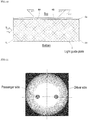
- light guide plate 1 illustrated in FIG. 10 has a rectangular sectional shape when viewed from an arrow D direction as illustrated in FIG. 12A .
- Light guide plate 1 illustrated in FIG. 10 may have a wedge sectional shape when viewed from the arrow D direction as illustrated in FIG. 12B .
- the present invention can be easily set in specifications requiring emission characteristics of the surface light source lighting device used for a backlight or the like of a display, and thus contributes to realization of stable display and improvement of reliability of various electronic apparatuses requiring a surface light source lighting device.
Landscapes
- Physics & Mathematics (AREA)
- General Physics & Mathematics (AREA)
- Optics & Photonics (AREA)
- Engineering & Computer Science (AREA)
- General Engineering & Computer Science (AREA)
- Planar Illumination Modules (AREA)
- Light Guides In General And Applications Therefor (AREA)
- Optical Couplings Of Light Guides (AREA)
- Liquid Crystal (AREA)
- Led Device Packages (AREA)
Claims (6)
- Dispositif d'éclairage de source de lumière de surface dans lequel la lumière est incidente sur une surface de bord (1L) d'une plaque de guidage de lumière (1) à partir d'une source de lumière (2a) afin de se propager à travers la plaque de guidage de lumière (1) et la lumière est émise à partir d'une surface avant de la plaque de guidage de lumière comprenant la surface avant et une surface arrière, le dispositif comprenant :la source de lumière (2a) comprenant une pluralité d'éléments de source de lumière (8) qui sont disposés avec un intervalle dans une direction longitudinale de la surface de bord (1L) de la plaque de guidage de lumière (1) ;un premier motif de guidage de lumière (4A) ayant un groupe de rainure linéaire dans une première direction oblique par rapport à une direction d'incidence de lumière à partir de la source de lumière (2a), le premier motif de guidage de lumière étant formé sur la surface arrière de la plaque de guidage de lumière (1) ; etun second motif de guidage de lumière (4B) ayant un groupe de rainure linéaire dans une seconde direction oblique qui est différente de la première direction oblique du premier motif de guidage de lumière (1) sur la surface arrière de la plaque de guidage de lumière (1),la lumière reflétée par le premier motif de guidage de lumière (4A) étant reflétée par le second motif de guidage de lumière (4B) et émise à partir de la surface avant de la plaque de guidage de lumière (1),caractérisé en ce que :
le dispositif d'éclairage de source de lumière comprend en outre :une partie incidente de lumière (3a) comprenant une lentille d'incidence de lumière (6) qui convertit la lumière linéaire incidente de la source de lumière (2a) en une lumière sensiblement parallèle ; etun volet (7) qui absorbe la lumière déviée de la lumière parallèle en lumière qui est passée par la lentille d'incidence de lumière (6) et à travers laquelle la lumière passe,dans lequel la lumière qui est passée à travers la partie d'incidence de lumière (3a) est incidente sur la surface de bord de la plaque de guidage de lumière (1), etdans lequel la lentille d'incidence de lumière (6) a des surfaces incurvées sur un côté de la source de lumière (2a) et sur un côté du volet (7) et une longueur de la lentille d'incidence de lumière (6) est plus petite qu'une distance d'un pas des éléments de source de lumière (8) de la source de lumière (2a). - Dispositif d'éclairage de source de lumière de surface selon la revendication 1,
dans lequel le volet (7) comprend :des parois de séparation (12) qui sont disposées avec un intervalle dans la direction longitudinale de la surface de bord (1L) de la plaque de guidage de lumière (1) et bloque la lumière incidente ;une surface de réflexion (13, 14) qui reflète la lumière qui est diffusée vers un côté de surface avant ou un côté de surface arrière de la plaque de guidage de lumière (1) depuis la zone située entre les parois de séparation (12) ; etune couche d'air ou une couche de résine qui est formée dans une région entourée par les parois de séparation (12) et la surface de réflexion (13, 14). - Dispositif d'éclairage de source de lumière de surface selon la revendication 2,
dans lequel un intervalle entre les parois de séparation (12) est dans une plage de 0,1 fois à 0,6 fois y compris une profondeur des parois de séparation (12). - Dispositif d'éclairage de source de lumière de surface selon la revendication 1,
dans lequel le premier motif de guidage de lumière (4A) est formé avec une première surface de réflexion de prisme principale (17) et une première surface de réflexion de prisme auxiliaire (18) ayant un plus grand angle de base incliné qu'un angle de base incliné de la première surface de réflexion de prisme principale (17),
dans lequel le second motif de guidage de lumière (4B) est formé avec une seconde surface de réflexion de prisme principale (19) et une seconde surface de réflexion de prisme auxiliaire (20) ayant un plus grand angle de base incliné qu'un angle de base incliné de la seconde surface de réflexion de prisme principale (19), et
dans lequel la lumière reflétée par la première surface de réflexion de prisme auxiliaire (17) est en outre reflétée par la seconde surface de réflexion de prisme principale (19), et est émise à partir de la surface avant de la plaque de guidage de lumière (1). - Dispositif d'éclairage de source de lumière de surface selon la revendication 4,
dans lequel, à 0,45 ou plus en tant que différence d'indice de réfraction entre un matériau formant la plaque de guidage de lumière (1) et l'air, un angle de base de la première surface de réflexion de prisme principale (17) du premier motif de guidage de lumière (4A) est au moins à 30° jusqu'à un maximum de 50°, et un angle de base de la première surface de réflexion de prisme auxiliaire (18) est au moins de 70° jusqu'à un maximum de 90°, et un angle de base de la seconde surface de réflexion de prisme principale (19) du second motif de guidage de lumière (4B) est au moins de 30° jusqu'à un maximum de 50° et un angle de base de la seconde surface de réflexion de prise auxiliaire (20) est au moins de 70° jusqu'à un maximum de 90°. - Dispositif d'éclairage de source de lumière de surface selon la revendication 4,
dans lequel, à 0,45 ou plus en tant que différence d'indice de réfraction entre un matériau formant la plaque de guidage de lumière (1) et l'air, un angle de base de la première surface de réflexion de prisme principale (17) du premier motif de guidage de lumière (4A) est au moins de 45° jusqu'à un maximum de 65°, et un angle de base de la première surface de réflexion de prisme auxiliaire (18) est au moins de 70° jusqu'à un maximum de 90°, et un angle de base de la seconde surface de réflexion de prisme principale (19) du second motif de guidage de lumière (19) est au moins de 45° jusqu'à un maximum de 65°, et un angle de base de la seconde surface de réflexion de prisme auxiliaire (20) est au moins de 70° jusqu'à un maximum de 90°.
Applications Claiming Priority (3)
| Application Number | Priority Date | Filing Date | Title |
|---|---|---|---|
| JP2015099560 | 2015-05-15 | ||
| JP2015252705A JP6478050B2 (ja) | 2015-05-15 | 2015-12-25 | 面光源照明装置 |
| PCT/JP2016/002079 WO2016185667A1 (fr) | 2015-05-15 | 2016-04-19 | Dispositif d'éclairage de source de lumière de surface |
Publications (3)
| Publication Number | Publication Date |
|---|---|
| EP3296616A1 EP3296616A1 (fr) | 2018-03-21 |
| EP3296616A4 EP3296616A4 (fr) | 2018-05-30 |
| EP3296616B1 true EP3296616B1 (fr) | 2019-07-24 |
Family
ID=57581928
Family Applications (1)
| Application Number | Title | Priority Date | Filing Date |
|---|---|---|---|
| EP16796064.0A Active EP3296616B1 (fr) | 2015-05-15 | 2016-04-19 | Dispositif d'éclairage de source de lumière de surface |
Country Status (4)
| Country | Link |
|---|---|
| US (1) | US10073209B2 (fr) |
| EP (1) | EP3296616B1 (fr) |
| JP (1) | JP6478050B2 (fr) |
| CN (1) | CN106796002B (fr) |
Families Citing this family (4)
| Publication number | Priority date | Publication date | Assignee | Title |
|---|---|---|---|---|
| JP6621881B1 (ja) * | 2018-08-03 | 2019-12-18 | 株式会社バンダイ | 液晶表示装置及びこれを用いた玩具 |
| JP2020085619A (ja) * | 2018-11-22 | 2020-06-04 | 豊田合成株式会社 | 表面検査用光源 |
| CN110242874A (zh) * | 2019-08-05 | 2019-09-17 | 成都工业学院 | 一种薄型灯具 |
| JP2023095239A (ja) * | 2021-12-24 | 2023-07-06 | パナソニックIpマネジメント株式会社 | 照明装置 |
Family Cites Families (27)
| Publication number | Priority date | Publication date | Assignee | Title |
|---|---|---|---|---|
| JPH0535361Y2 (fr) * | 1986-09-25 | 1993-09-08 | ||
| JP3644787B2 (ja) * | 1996-05-09 | 2005-05-11 | 松下電器産業株式会社 | 面状照明系 |
| US5980054A (en) | 1996-05-09 | 1999-11-09 | Matsushita Electric Industrial Co., Ltd. | Panel-form illuminating system |
| JP3862926B2 (ja) * | 2000-03-31 | 2006-12-27 | 株式会社エンプラス | 面光源装置及び液晶ディスプレイ |
| JP4142234B2 (ja) * | 2000-07-04 | 2008-09-03 | 株式会社エンプラス | 面光源装置及び液晶表示装置 |
| JP4225448B2 (ja) * | 2000-08-01 | 2009-02-18 | 株式会社エンプラス | 導光板、面光源装置及び表示装置 |
| JP4363758B2 (ja) * | 2000-08-02 | 2009-11-11 | 株式会社エンプラス | 導光板、面光源装置及び表示装置 |
| JP3742570B2 (ja) * | 2000-08-11 | 2006-02-08 | 株式会社エンプラス | 導光板、面光源装置及び表示装置 |
| JP4145473B2 (ja) * | 2000-08-17 | 2008-09-03 | 株式会社エンプラス | 面光源装置及び液晶表示装置 |
| JP4152605B2 (ja) * | 2001-05-30 | 2008-09-17 | 株式会社エンプラス | 導光板、面光源装置及び液晶ディスプレイ |
| KR100799156B1 (ko) * | 2001-07-13 | 2008-01-29 | 삼성전자주식회사 | 도광판, 이의 제조 방법, 이를 이용한 액정표시장치 |
| JP4035998B2 (ja) * | 2002-01-23 | 2008-01-23 | オムロン株式会社 | 面光源装置、拡散板及び液晶表示装置 |
| JP4020397B2 (ja) * | 2004-06-14 | 2007-12-12 | 惠次 飯村 | 点光源を用いた面光源 |
| CN100403110C (zh) * | 2004-08-31 | 2008-07-16 | 鸿富锦精密工业(深圳)有限公司 | 导光板 |
| JP2006086075A (ja) | 2004-09-17 | 2006-03-30 | Alps Electric Co Ltd | 面発光装置、背面照明装置および液晶表示装置 |
| CN101061347A (zh) * | 2004-11-19 | 2007-10-24 | 日立化成工业株式会社 | 导光板 |
| KR101263502B1 (ko) * | 2006-03-27 | 2013-05-13 | 엘지디스플레이 주식회사 | 엘이디 백라이트 유닛 및 이를 구비한 액정표시장치 |
| WO2008038754A1 (fr) * | 2006-09-29 | 2008-04-03 | Toray Industries, Inc. | Source lumineuse en surface et dispositif d'affichage à cristaux liquides utilisant celle-ci |
| CN201032081Y (zh) * | 2007-04-09 | 2008-03-05 | 台湾奈普光电科技股份有限公司 | 背光模块 |
| US8118468B2 (en) | 2008-05-16 | 2012-02-21 | Qualcomm Mems Technologies, Inc. | Illumination apparatus and methods |
| KR101499847B1 (ko) * | 2008-07-03 | 2015-03-09 | 삼성디스플레이 주식회사 | 도광판 및 이를 포함하는 백라이트 유닛 |
| JP2011014520A (ja) | 2008-12-04 | 2011-01-20 | Seiko Instruments Inc | 照明装置及び表示装置 |
| JP5510038B2 (ja) | 2010-04-28 | 2014-06-04 | オムロン株式会社 | コリメート光源及び面光源装置 |
| JP5725349B2 (ja) * | 2011-07-25 | 2015-05-27 | ミネベア株式会社 | 面状照明装置 |
| JP2015035252A (ja) * | 2011-11-30 | 2015-02-19 | シャープ株式会社 | 光源装置、面光源装置、表示装置および照明装置 |
| JP5917180B2 (ja) | 2012-02-09 | 2016-05-11 | ミネベア株式会社 | 面状照明装置 |
| CN103939790B (zh) * | 2013-01-22 | 2016-11-23 | 群创光电股份有限公司 | 显示装置及其发光模块 |
-
2015
- 2015-12-25 JP JP2015252705A patent/JP6478050B2/ja active Active
-
2016
- 2016-04-19 EP EP16796064.0A patent/EP3296616B1/fr active Active
- 2016-04-19 US US15/327,655 patent/US10073209B2/en active Active
- 2016-04-19 CN CN201680002081.6A patent/CN106796002B/zh active Active
Non-Patent Citations (1)
| Title |
|---|
| None * |
Also Published As
| Publication number | Publication date |
|---|---|
| JP6478050B2 (ja) | 2019-03-06 |
| CN106796002B (zh) | 2020-07-03 |
| CN106796002A (zh) | 2017-05-31 |
| US10073209B2 (en) | 2018-09-11 |
| EP3296616A1 (fr) | 2018-03-21 |
| EP3296616A4 (fr) | 2018-05-30 |
| JP2016219396A (ja) | 2016-12-22 |
| US20170205557A1 (en) | 2017-07-20 |
Similar Documents
| Publication | Publication Date | Title |
|---|---|---|
| KR102286530B1 (ko) | 면 광원 장치, 표시 장치 및 전자 기기 | |
| KR101274891B1 (ko) | 화면에 화상을 투영하기 위한 헤드업 디스플레이 장치 | |
| KR100971639B1 (ko) | 발광 장치, 면광원 장치, 표시 장치 및 광속 제어 부재 | |
| US7217025B2 (en) | Backlight unit | |
| US9310546B2 (en) | Backlight unit and display device having the same | |
| EP2958097B1 (fr) | Appareil d'affichage | |
| EP2333401B1 (fr) | Dispositif à source lumineuse et dispositif d éclairage utilisant ce dernier | |
| KR20170063647A (ko) | 헤드업 디스플레이 장치 | |
| KR20040048803A (ko) | 면상 광원장치 및 표시장치 | |
| CN107850282A (zh) | 用于机动车大灯的发光机构 | |
| US7794100B2 (en) | Planar light source apparatus, display apparatus and planar illumination method | |
| US9453958B2 (en) | Light guide plate and illumination apparatus | |
| EP3296616B1 (fr) | Dispositif d'éclairage de source de lumière de surface | |
| KR102081724B1 (ko) | 디스플레이 장치의 백라이트 유닛 | |
| KR100814559B1 (ko) | 백라이트 장치 및 액정 표시 장치 | |
| US20140313772A1 (en) | Illumination device, and display device provided therewith | |
| KR100818280B1 (ko) | 면발광장치 및 이를 채용한 디스플레이 장치 | |
| US20130182200A1 (en) | Light guide plate, illumination device, and liquid crystal display device | |
| WO2014077013A1 (fr) | Unité de source de lumière et dispositif d'éclairage | |
| KR20090113682A (ko) | 디스플레이장치 | |
| JP2007256697A (ja) | 液晶表示装置 | |
| CN220473724U (zh) | 扩散部件、显示装置、平视显示器装置及交通工具 | |
| CN210222287U (zh) | 导光板及光源模块 | |
| WO2013132539A1 (fr) | Appareil d'éclairage et appareil d'affichage à cristaux liquides l'utilisant | |
| CN120936932A (zh) | 抬头显示单元 |
Legal Events
| Date | Code | Title | Description |
|---|---|---|---|
| STAA | Information on the status of an ep patent application or granted ep patent |
Free format text: STATUS: THE INTERNATIONAL PUBLICATION HAS BEEN MADE |
|
| PUAI | Public reference made under article 153(3) epc to a published international application that has entered the european phase |
Free format text: ORIGINAL CODE: 0009012 |
|
| STAA | Information on the status of an ep patent application or granted ep patent |
Free format text: STATUS: REQUEST FOR EXAMINATION WAS MADE |
|
| 17P | Request for examination filed |
Effective date: 20161223 |
|
| AK | Designated contracting states |
Kind code of ref document: A1 Designated state(s): AL AT BE BG CH CY CZ DE DK EE ES FI FR GB GR HR HU IE IS IT LI LT LU LV MC MK MT NL NO PL PT RO RS SE SI SK SM TR |
|
| AX | Request for extension of the european patent |
Extension state: BA ME |
|
| A4 | Supplementary search report drawn up and despatched |
Effective date: 20180504 |
|
| RIC1 | Information provided on ipc code assigned before grant |
Ipc: F21V 8/00 20060101ALI20180424BHEP Ipc: F21Y 115/10 20160101ALI20180424BHEP Ipc: F21S 2/00 20160101AFI20180424BHEP |
|
| DAV | Request for validation of the european patent (deleted) | ||
| DAX | Request for extension of the european patent (deleted) | ||
| RIC1 | Information provided on ipc code assigned before grant |
Ipc: F21S 2/00 20160101AFI20190226BHEP Ipc: F21V 8/00 20060101ALI20190226BHEP Ipc: F21Y 115/10 20160101ALI20190226BHEP |
|
| GRAP | Despatch of communication of intention to grant a patent |
Free format text: ORIGINAL CODE: EPIDOSNIGR1 |
|
| STAA | Information on the status of an ep patent application or granted ep patent |
Free format text: STATUS: GRANT OF PATENT IS INTENDED |
|
| INTG | Intention to grant announced |
Effective date: 20190430 |
|
| GRAS | Grant fee paid |
Free format text: ORIGINAL CODE: EPIDOSNIGR3 |
|
| GRAA | (expected) grant |
Free format text: ORIGINAL CODE: 0009210 |
|
| STAA | Information on the status of an ep patent application or granted ep patent |
Free format text: STATUS: THE PATENT HAS BEEN GRANTED |
|
| AK | Designated contracting states |
Kind code of ref document: B1 Designated state(s): AL AT BE BG CH CY CZ DE DK EE ES FI FR GB GR HR HU IE IS IT LI LT LU LV MC MK MT NL NO PL PT RO RS SE SI SK SM TR |
|
| REG | Reference to a national code |
Ref country code: GB Ref legal event code: FG4D |
|
| REG | Reference to a national code |
Ref country code: CH Ref legal event code: EP |
|
| REG | Reference to a national code |
Ref country code: DE Ref legal event code: R096 Ref document number: 602016017493 Country of ref document: DE |
|
| REG | Reference to a national code |
Ref country code: AT Ref legal event code: REF Ref document number: 1158622 Country of ref document: AT Kind code of ref document: T Effective date: 20190815 |
|
| REG | Reference to a national code |
Ref country code: IE Ref legal event code: FG4D |
|
| REG | Reference to a national code |
Ref country code: NL Ref legal event code: MP Effective date: 20190724 |
|
| REG | Reference to a national code |
Ref country code: LT Ref legal event code: MG4D |
|
| REG | Reference to a national code |
Ref country code: AT Ref legal event code: MK05 Ref document number: 1158622 Country of ref document: AT Kind code of ref document: T Effective date: 20190724 |
|
| PG25 | Lapsed in a contracting state [announced via postgrant information from national office to epo] |
Ref country code: SE Free format text: LAPSE BECAUSE OF FAILURE TO SUBMIT A TRANSLATION OF THE DESCRIPTION OR TO PAY THE FEE WITHIN THE PRESCRIBED TIME-LIMIT Effective date: 20190724 Ref country code: NL Free format text: LAPSE BECAUSE OF FAILURE TO SUBMIT A TRANSLATION OF THE DESCRIPTION OR TO PAY THE FEE WITHIN THE PRESCRIBED TIME-LIMIT Effective date: 20190724 Ref country code: BG Free format text: LAPSE BECAUSE OF FAILURE TO SUBMIT A TRANSLATION OF THE DESCRIPTION OR TO PAY THE FEE WITHIN THE PRESCRIBED TIME-LIMIT Effective date: 20191024 Ref country code: NO Free format text: LAPSE BECAUSE OF FAILURE TO SUBMIT A TRANSLATION OF THE DESCRIPTION OR TO PAY THE FEE WITHIN THE PRESCRIBED TIME-LIMIT Effective date: 20191024 Ref country code: HR Free format text: LAPSE BECAUSE OF FAILURE TO SUBMIT A TRANSLATION OF THE DESCRIPTION OR TO PAY THE FEE WITHIN THE PRESCRIBED TIME-LIMIT Effective date: 20190724 Ref country code: AT Free format text: LAPSE BECAUSE OF FAILURE TO SUBMIT A TRANSLATION OF THE DESCRIPTION OR TO PAY THE FEE WITHIN THE PRESCRIBED TIME-LIMIT Effective date: 20190724 Ref country code: PT Free format text: LAPSE BECAUSE OF FAILURE TO SUBMIT A TRANSLATION OF THE DESCRIPTION OR TO PAY THE FEE WITHIN THE PRESCRIBED TIME-LIMIT Effective date: 20191125 Ref country code: LT Free format text: LAPSE BECAUSE OF FAILURE TO SUBMIT A TRANSLATION OF THE DESCRIPTION OR TO PAY THE FEE WITHIN THE PRESCRIBED TIME-LIMIT Effective date: 20190724 Ref country code: FI Free format text: LAPSE BECAUSE OF FAILURE TO SUBMIT A TRANSLATION OF THE DESCRIPTION OR TO PAY THE FEE WITHIN THE PRESCRIBED TIME-LIMIT Effective date: 20190724 |
|
| PG25 | Lapsed in a contracting state [announced via postgrant information from national office to epo] |
Ref country code: GR Free format text: LAPSE BECAUSE OF FAILURE TO SUBMIT A TRANSLATION OF THE DESCRIPTION OR TO PAY THE FEE WITHIN THE PRESCRIBED TIME-LIMIT Effective date: 20191025 Ref country code: ES Free format text: LAPSE BECAUSE OF FAILURE TO SUBMIT A TRANSLATION OF THE DESCRIPTION OR TO PAY THE FEE WITHIN THE PRESCRIBED TIME-LIMIT Effective date: 20190724 Ref country code: RS Free format text: LAPSE BECAUSE OF FAILURE TO SUBMIT A TRANSLATION OF THE DESCRIPTION OR TO PAY THE FEE WITHIN THE PRESCRIBED TIME-LIMIT Effective date: 20190724 Ref country code: IS Free format text: LAPSE BECAUSE OF FAILURE TO SUBMIT A TRANSLATION OF THE DESCRIPTION OR TO PAY THE FEE WITHIN THE PRESCRIBED TIME-LIMIT Effective date: 20191124 Ref country code: AL Free format text: LAPSE BECAUSE OF FAILURE TO SUBMIT A TRANSLATION OF THE DESCRIPTION OR TO PAY THE FEE WITHIN THE PRESCRIBED TIME-LIMIT Effective date: 20190724 Ref country code: LV Free format text: LAPSE BECAUSE OF FAILURE TO SUBMIT A TRANSLATION OF THE DESCRIPTION OR TO PAY THE FEE WITHIN THE PRESCRIBED TIME-LIMIT Effective date: 20190724 |
|
| PG25 | Lapsed in a contracting state [announced via postgrant information from national office to epo] |
Ref country code: TR Free format text: LAPSE BECAUSE OF FAILURE TO SUBMIT A TRANSLATION OF THE DESCRIPTION OR TO PAY THE FEE WITHIN THE PRESCRIBED TIME-LIMIT Effective date: 20190724 |
|
| PG25 | Lapsed in a contracting state [announced via postgrant information from national office to epo] |
Ref country code: RO Free format text: LAPSE BECAUSE OF FAILURE TO SUBMIT A TRANSLATION OF THE DESCRIPTION OR TO PAY THE FEE WITHIN THE PRESCRIBED TIME-LIMIT Effective date: 20190724 Ref country code: DK Free format text: LAPSE BECAUSE OF FAILURE TO SUBMIT A TRANSLATION OF THE DESCRIPTION OR TO PAY THE FEE WITHIN THE PRESCRIBED TIME-LIMIT Effective date: 20190724 Ref country code: IT Free format text: LAPSE BECAUSE OF FAILURE TO SUBMIT A TRANSLATION OF THE DESCRIPTION OR TO PAY THE FEE WITHIN THE PRESCRIBED TIME-LIMIT Effective date: 20190724 Ref country code: EE Free format text: LAPSE BECAUSE OF FAILURE TO SUBMIT A TRANSLATION OF THE DESCRIPTION OR TO PAY THE FEE WITHIN THE PRESCRIBED TIME-LIMIT Effective date: 20190724 Ref country code: PL Free format text: LAPSE BECAUSE OF FAILURE TO SUBMIT A TRANSLATION OF THE DESCRIPTION OR TO PAY THE FEE WITHIN THE PRESCRIBED TIME-LIMIT Effective date: 20190724 |
|
| PG25 | Lapsed in a contracting state [announced via postgrant information from national office to epo] |
Ref country code: IS Free format text: LAPSE BECAUSE OF FAILURE TO SUBMIT A TRANSLATION OF THE DESCRIPTION OR TO PAY THE FEE WITHIN THE PRESCRIBED TIME-LIMIT Effective date: 20200224 Ref country code: SK Free format text: LAPSE BECAUSE OF FAILURE TO SUBMIT A TRANSLATION OF THE DESCRIPTION OR TO PAY THE FEE WITHIN THE PRESCRIBED TIME-LIMIT Effective date: 20190724 Ref country code: SM Free format text: LAPSE BECAUSE OF FAILURE TO SUBMIT A TRANSLATION OF THE DESCRIPTION OR TO PAY THE FEE WITHIN THE PRESCRIBED TIME-LIMIT Effective date: 20190724 Ref country code: CZ Free format text: LAPSE BECAUSE OF FAILURE TO SUBMIT A TRANSLATION OF THE DESCRIPTION OR TO PAY THE FEE WITHIN THE PRESCRIBED TIME-LIMIT Effective date: 20190724 |
|
| REG | Reference to a national code |
Ref country code: DE Ref legal event code: R097 Ref document number: 602016017493 Country of ref document: DE |
|
| PLBE | No opposition filed within time limit |
Free format text: ORIGINAL CODE: 0009261 |
|
| STAA | Information on the status of an ep patent application or granted ep patent |
Free format text: STATUS: NO OPPOSITION FILED WITHIN TIME LIMIT |
|
| PG2D | Information on lapse in contracting state deleted |
Ref country code: IS |
|
| 26N | No opposition filed |
Effective date: 20200603 |
|
| PG25 | Lapsed in a contracting state [announced via postgrant information from national office to epo] |
Ref country code: SI Free format text: LAPSE BECAUSE OF FAILURE TO SUBMIT A TRANSLATION OF THE DESCRIPTION OR TO PAY THE FEE WITHIN THE PRESCRIBED TIME-LIMIT Effective date: 20190724 |
|
| PG25 | Lapsed in a contracting state [announced via postgrant information from national office to epo] |
Ref country code: MC Free format text: LAPSE BECAUSE OF FAILURE TO SUBMIT A TRANSLATION OF THE DESCRIPTION OR TO PAY THE FEE WITHIN THE PRESCRIBED TIME-LIMIT Effective date: 20190724 |
|
| REG | Reference to a national code |
Ref country code: CH Ref legal event code: PL |
|
| PG25 | Lapsed in a contracting state [announced via postgrant information from national office to epo] |
Ref country code: CH Free format text: LAPSE BECAUSE OF NON-PAYMENT OF DUE FEES Effective date: 20200430 Ref country code: LI Free format text: LAPSE BECAUSE OF NON-PAYMENT OF DUE FEES Effective date: 20200430 Ref country code: LU Free format text: LAPSE BECAUSE OF NON-PAYMENT OF DUE FEES Effective date: 20200419 |
|
| REG | Reference to a national code |
Ref country code: BE Ref legal event code: MM Effective date: 20200430 |
|
| PG25 | Lapsed in a contracting state [announced via postgrant information from national office to epo] |
Ref country code: BE Free format text: LAPSE BECAUSE OF NON-PAYMENT OF DUE FEES Effective date: 20200430 |
|
| PG25 | Lapsed in a contracting state [announced via postgrant information from national office to epo] |
Ref country code: IE Free format text: LAPSE BECAUSE OF NON-PAYMENT OF DUE FEES Effective date: 20200419 |
|
| PG25 | Lapsed in a contracting state [announced via postgrant information from national office to epo] |
Ref country code: MT Free format text: LAPSE BECAUSE OF FAILURE TO SUBMIT A TRANSLATION OF THE DESCRIPTION OR TO PAY THE FEE WITHIN THE PRESCRIBED TIME-LIMIT Effective date: 20190724 Ref country code: CY Free format text: LAPSE BECAUSE OF FAILURE TO SUBMIT A TRANSLATION OF THE DESCRIPTION OR TO PAY THE FEE WITHIN THE PRESCRIBED TIME-LIMIT Effective date: 20190724 |
|
| PG25 | Lapsed in a contracting state [announced via postgrant information from national office to epo] |
Ref country code: MK Free format text: LAPSE BECAUSE OF FAILURE TO SUBMIT A TRANSLATION OF THE DESCRIPTION OR TO PAY THE FEE WITHIN THE PRESCRIBED TIME-LIMIT Effective date: 20190724 |
|
| PGFP | Annual fee paid to national office [announced via postgrant information from national office to epo] |
Ref country code: DE Payment date: 20250422 Year of fee payment: 10 |
|
| PGFP | Annual fee paid to national office [announced via postgrant information from national office to epo] |
Ref country code: GB Payment date: 20250423 Year of fee payment: 10 |
|
| PGFP | Annual fee paid to national office [announced via postgrant information from national office to epo] |
Ref country code: FR Payment date: 20250425 Year of fee payment: 10 |