EP3296659B1 - Montageplatte für einen modularen mauerkasten - Google Patents
Montageplatte für einen modularen mauerkasten Download PDFInfo
- Publication number
- EP3296659B1 EP3296659B1 EP17189789.5A EP17189789A EP3296659B1 EP 3296659 B1 EP3296659 B1 EP 3296659B1 EP 17189789 A EP17189789 A EP 17189789A EP 3296659 B1 EP3296659 B1 EP 3296659B1
- Authority
- EP
- European Patent Office
- Prior art keywords
- air outlet
- mounting plate
- receptacle
- holder
- adapter
- Prior art date
- Legal status (The legal status is an assumption and is not a legal conclusion. Google has not performed a legal analysis and makes no representation as to the accuracy of the status listed.)
- Active
Links
Images












Classifications
-
- F—MECHANICAL ENGINEERING; LIGHTING; HEATING; WEAPONS; BLASTING
- F24—HEATING; RANGES; VENTILATING
- F24F—AIR-CONDITIONING; AIR-HUMIDIFICATION; VENTILATION; USE OF AIR CURRENTS FOR SCREENING
- F24F13/00—Details common to, or for air-conditioning, air-humidification, ventilation or use of air currents for screening
- F24F13/08—Air-flow control members, e.g. louvres, grilles, flaps or guide plates
- F24F13/082—Grilles, registers or guards
-
- F—MECHANICAL ENGINEERING; LIGHTING; HEATING; WEAPONS; BLASTING
- F24—HEATING; RANGES; VENTILATING
- F24F—AIR-CONDITIONING; AIR-HUMIDIFICATION; VENTILATION; USE OF AIR CURRENTS FOR SCREENING
- F24F13/00—Details common to, or for air-conditioning, air-humidification, ventilation or use of air currents for screening
- F24F13/08—Air-flow control members, e.g. louvres, grilles, flaps or guide plates
- F24F13/082—Grilles, registers or guards
- F24F13/084—Grilles, registers or guards with mounting arrangements, e.g. snap fasteners for mounting to the wall or duct
-
- F—MECHANICAL ENGINEERING; LIGHTING; HEATING; WEAPONS; BLASTING
- F24—HEATING; RANGES; VENTILATING
- F24F—AIR-CONDITIONING; AIR-HUMIDIFICATION; VENTILATION; USE OF AIR CURRENTS FOR SCREENING
- F24F13/00—Details common to, or for air-conditioning, air-humidification, ventilation or use of air currents for screening
- F24F13/08—Air-flow control members, e.g. louvres, grilles, flaps or guide plates
- F24F13/10—Air-flow control members, e.g. louvres, grilles, flaps or guide plates movable, e.g. dampers
- F24F13/14—Air-flow control members, e.g. louvres, grilles, flaps or guide plates movable, e.g. dampers built up of tilting members, e.g. louvre
-
- F—MECHANICAL ENGINEERING; LIGHTING; HEATING; WEAPONS; BLASTING
- F24—HEATING; RANGES; VENTILATING
- F24F—AIR-CONDITIONING; AIR-HUMIDIFICATION; VENTILATION; USE OF AIR CURRENTS FOR SCREENING
- F24F7/00—Ventilation
- F24F7/003—Ventilation in combination with air cleaning
-
- F—MECHANICAL ENGINEERING; LIGHTING; HEATING; WEAPONS; BLASTING
- F24—HEATING; RANGES; VENTILATING
- F24F—AIR-CONDITIONING; AIR-HUMIDIFICATION; VENTILATION; USE OF AIR CURRENTS FOR SCREENING
- F24F7/00—Ventilation
- F24F2007/001—Ventilation with exhausting air ducts
-
- F—MECHANICAL ENGINEERING; LIGHTING; HEATING; WEAPONS; BLASTING
- F24—HEATING; RANGES; VENTILATING
- F24F—AIR-CONDITIONING; AIR-HUMIDIFICATION; VENTILATION; USE OF AIR CURRENTS FOR SCREENING
- F24F7/00—Ventilation
- F24F2007/0025—Ventilation using vent ports in a wall
-
- F—MECHANICAL ENGINEERING; LIGHTING; HEATING; WEAPONS; BLASTING
- F24—HEATING; RANGES; VENTILATING
- F24F—AIR-CONDITIONING; AIR-HUMIDIFICATION; VENTILATION; USE OF AIR CURRENTS FOR SCREENING
- F24F2221/00—Details or features not otherwise provided for
- F24F2221/36—Modules, e.g. for an easy mounting or transport
Definitions
- the present invention relates to a mounting plate for a modular wall box, wherein the mounting plate has a front side, a back side and an air passage opening connecting the front side and the back side.
- Wall boxes are used to exchange air in order to improve the indoor climate in rooms, particularly in living areas, e.g. in the kitchen or bathroom. "Used” air is discharged from the inside of a building to the outside through an air passage opening in the wall box, while “fresh” air enters the room through the air passage opening.
- a wall box has a pipe section connected to a mounting plate.
- the pipe section can be connected to an air outlet pipe on the wall side or at least inserted into a hole in the wall to which the mounting plate is to be attached, with the pipe section itself being connected to the air passage opening in the mounting plate. Since the mounting plate is also used to attach the wall box, the back of the mounting plate faces the wall of the room through which the air exchange is to take place.
- the front of the mounting plate is arranged opposite the back.
- German patent application DE 26 06 011 A1 concerns a connection device for exhaust air pipes with a frame. Either a grille insert or a backflow flap can be connected to the frame.
- the US patent US 5,791,985 A relates to a wall box with a mounting plate, to which a cover and an insect screen can be attached.
- US 2005/0202778 A1 and US 2010/0159821 A1 also each concern a wall box with a mounting plate. The components of the wall box are connected to each other in a cascading manner.
- the US 2005/0202778 A1 a wall box according to the preamble of claim 1.
- the US patent application US 2009/0081942 A1 relates to a wall box with a mounting plate, to which a ventilation flap and a cover as well as a connecting pipe can be attached.
- a modular wall box with the features of claim 1, wherein the wall box has a mounting plate, an air outlet panel at least partially covering an air passage opening of the mounting plate and a front panel at least partially covering a front side of the mounting plate, wherein the mounting plate has a front panel holder, wherein the front panel is detachably fastened to the front panel holder, wherein the front panel holder and the front panel have mutually complementary fastening means which are detachably engaged with one another, wherein the mounting plate has the front side, a rear side and an air passage opening connecting the front side and the rear side, wherein at least one air outlet pipe holder is arranged on the rear side of the mounting plate, which is designed in such a way that a wall-side air outlet pipe can be detachably fastened to the air outlet pipe holder of the mounting plate, wherein the wall box has an adapter for connecting the air passage opening of the mounting plate to a wall-side air outlet pipe or a Wall opening, wherein
- the mounting plate designed according to the invention is the basic element for a modular wall box.
- the modular design of the wall box allows individual components of the wall box to be added, replaced or removed by connecting them to or detaching them from the mounting plate.
- the mounting plate can be used, like a modular system, to construct a large number of wall boxes, the individual components of which differ and are tailored to the local conditions and customer requirements.
- the term "detachably attachable” includes mechanical connections that are brought about by a positive and/or force fit.
- adhesive or welded connections are not “detachable” in the sense of the present invention.
- air passage opening used in the context of the present invention do not limit the flow directions through the respective opening, but are used solely to better distinguish between the different openings.
- the back of the mounting plate When mounted, the back of the mounting plate is usually facing a wall or masonry through which the air exchange is to take place.
- the air outlet pipe holder arranged on the back of the mounting plate is designed in such a way that an air outlet pipe on the wall side can be detachably attached to the air outlet pipe holder.
- the air outlet cover holder arranged on the front of the mounting plate is designed in such a way that an air outlet cover that at least partially covers the air passage opening is detachably attached to the air outlet cover holder.
- an air outlet cover is first of all a cover that at least partially covers the air passage opening and is possibly suitable for changing the main flow direction of an air flow flowing through the air passage opening.
- an air outlet cover in one embodiment has air guide elements that extend at least partially over the air passage opening.
- an air outlet cover is detachably attached to the mounting plate.
- the detachable attachment means that the air outlet cover holder can be used with a variety of different air outlet covers and the air outlet pipe holder can be used with a variety of different air outlet pipes.
- Which air outlet cover and which air outlet pipe should be attached to the mounting plate to design the wall box can be decided depending on the customer's specifications and the conditions at the installation site. This means that stockpiling prefabricated wall boxes can be avoided.
- the air outlet cover holder has fastening means, wherein the fastening means are designed such that the air outlet cover is detachably fastened to the fastening means of the air outlet cover holder, preferably the fastening means have locking means and/or a screw thread.
- the air outlet cover and the air outlet cover holder have fastening means, wherein the fastening means are designed to be complementary to one another in such a way that the fastening means of the air outlet cover and the fastening means of the air outlet cover holder are detachably engaged with one another.
- an adapter is a transition piece which can be detachably attached to the wall-side air outlet pipe or to a wall opening as well as to the mounting plate in order to pass an air flow through the air passage opening of the mounting plate.
- the adapter is detachably connected to the wall-side air outlet pipe and to the adapter holder on the back of the mounting plate in order to put the wall box into operation.
- the adapter and the adapter holder of the mounting plate have mutually engaging, complementary fastening means for releasably fastening the adapter in the adapter holder, wherein the fastening means preferably have locking means and/or a screw thread.
- the mounting plate further comprises a front panel holder, wherein the front panel holder is designed such that a front panel that at least partially covers the front side of the mounting plate is detachably attached to the front panel holder.
- the front panel holder is preferably arranged on the front side of the mounting plate.
- the front panel holder has fastening means which are designed such that a front panel is detachably fastened to the front panel holder using the fastening means.
- the fastening means are preferably locking means.
- the front panel and the front panel holder have fastening means which are complementary to one another for detachable engagement with one another, wherein the fastening means preferably have locking means which are complementary to one another and/or complementary screw threads.
- a front panel is first of all a component of a wall box which, in a state in which the front panel is detachably attached to the mounting plate by the front panel holder, at least partially covers the front of the mounting plate.
- a front panel attached to the front panel holder protects the mounting plate and the components arranged under the front panel from environmental influences and forms a front closure of the wall box.
- the mounting plate has a seal receptacle on its rear side, wherein the seal receptacle is designed such that a seal can be detachably fastened to the seal receptacle on the mounting plate.
- a seal detachably attached to the seal holder prevents air and/or moisture from penetrating into the wall box between the mounting plate and a wall on which the mounting plate is arranged in an assembled state.
- the mounting plate has an insect screen holder on its front side, wherein the insect screen holder is designed such that an insect screen can be detachably fastened to the insect screen holder.
- insect screen includes a screen that extends over the air passage opening, which can be detachably attached to the insect screen holder and prevents insects, pests and/or pollen from entering through the air passage opening of the mounting plate.
- the insect screen thus prevents insects and/or pests from entering a room ventilated with the modular wall box through the air passage opening.
- Each receptacle described in connection with specific embodiments of the mounting plate is independent of the presence of other/further Receptacles are disclosed. It is understood that the presence of a component detachably attached to a receptacle in the sense of the present invention requires a correspondingly designed receptacle. On the other hand, the presence of a receptacle arranged on the mounting plate does not require that a component is detachably attached to this receptacle.
- the mounting plate can have an insect screen holder on its front side in addition to the air outlet panel holder and a sealing element holder on its back side in addition to the air outlet pipe holder in the form of an adapter holder.
- the front panel holder can also be arranged on a side surface of the mounting plate.
- the mounting plate is rotationally symmetrical in a plan view of its front side with respect to the center of the air passage opening.
- the mounting plate has a circular, rectangular, star-shaped or substantially triangular outer contour in a plan view of its front side.
- the mounting plate has a star-shaped, essentially triangular outer contour in a plan view of its front side, wherein, starting from a centrally arranged, circular air passage opening that connects the front side to the back side, the mounting plate has several, preferably three, circular-arc-shaped edge sections that are arranged evenly, preferably rotationally symmetrical by 120°, to the center of the air passage opening. Two of the edge sections are connected by a further wing section, which is preferably circular-arc-shaped. The outer edge of the wing section that describes the circular-arc shape has a larger radius than the edge sections connected to it.
- the mounting plate has fastening means, wherein the fastening means are designed such that the mounting plate can be fastened to a wall with the fastening means.
- the mounting plate has openings, preferably elongated holes, for the passage of fastening means, preferably screws, in sections.
- the openings are arranged at equidistant intervals around the air passage opening. If the mounting plate has a star-shaped outer contour in a plan view of the mounting plate, each wing section preferably has an opening.
- the mounting plate has, in addition to the air passage opening, at least one cable duct connecting the front and the back of the mounting plate. Cables for connecting electrical components can be passed through the mounting plate through the cable duct.
- a light source arranged on the front of the wall box can be electrically connected to a power supply with a cable passed through the cable duct.
- a design element described below can have a light source that can be connected to a power supply with a cable that can be passed through the cable duct.
- the cable duct can be broken out of the material of the mounting plate along a closed predetermined breaking line.
- a cable duct provided on the mounting plate in this way is initially closed. If the cable duct is required, the material of the mounting plate covering the cable duct can be removed along the predetermined breaking line and the cable duct can thus be made usable.
- the mounting plate in one embodiment has a star-shaped outer contour with three wing sections in a plan view of its front, then preferably two of the wing sections each have a cable duct connecting the front and the back of the mounting plate.
- the rear side and/or the front side of the mounting plate has at least one cavity, wherein the cavity is designed such that an insulating material can be arranged in the cavity.
- an insulating material is arranged in the at least one cavity, wherein the insulating material is preferably a polymer, preferably a polystyrene.
- the insect screen holder, the air outlet panel holder and the front panel holder are arranged in a sequence from the inside to the outside. If one or more of the above-mentioned holders are not provided in a further embodiment, this does not change the above-mentioned sequence. The missing holder is deleted from the above-mentioned sequence. The sequence of the remaining holders remains as described.
- the receptacles are arranged concentrically to the air passage opening of the mounting plate.
- the air outlet pipe receptacle whether it is designed as an adapter receptacle or not, and/or the air outlet panel receptacle and/or the front panel receptacle and/or the seal receptacle and/or the insect screen receptacle are arranged concentrically to the air passage opening.
- the air outlet cover receptacle can be designed according to the variations described below, whereby the variations described can be combined with one another unless technically impossible.
- the air outlet cover holder has an anti-twist device that is designed such that an air outlet cover can be fastened in a rotationally fixed manner in the air outlet cover holder.
- the anti-twist device prevents the air outlet cover from being accidentally rotated in the air outlet cover holder.
- the air outlet panel holder has a drip edge and/or a drip opening which is designed such that liquid accumulating in or on the air outlet panel holder during operation of the wall box can be drained off through the drip edge and/or the drip opening.
- the air outlet cover receptacle has a groove or a web, the groove or the web extending at least in sections parallel to the outer contour of the air passage opening of the mounting plate.
- the air outlet cover receptacle has a plurality, preferably three, four or more groove or web sections, which are arranged at equidistant intervals from one another along and parallel to the outer contour of the air passage opening of the mounting plate.
- the air outlet panel holder has a groove or at least one groove section
- the groove is designed such that it can be brought into engagement with a web of an air outlet panel, preferably in a form-fitting and/or force-fitting manner
- the at least one groove section is designed such that it can be brought into engagement with a groove section of an air outlet panel, preferably in a form-fitting and/or force-fitting manner.
- the mounting plate has an air outlet panel with an air outlet opening, an air inlet opening and a fastening ring connecting the air inlet opening and air outlet opening, wherein the air outlet panel is detachably fastened to the air outlet panel holder of the mounting plate, so that the air outlet opening of the air outlet panel is fluidically connected to the air passage opening of the mounting plate.
- the fastening means of the air outlet cover and the air outlet cover holder have mutually complementary locking means and/or mutually complementary screw threads.
- the fastening means of the air outlet cover are arranged on its fastening ring.
- the air outlet panel and the air outlet panel holder have an anti-twist device that is designed such that the air outlet panel can be fastened in a rotationally fixed manner in the air outlet panel holder.
- the anti-twist device prevents the air outlet panel from being accidentally rotated in the air outlet panel holder.
- the anti-twist device of the air outlet panel is preferably arranged on its fastening ring.
- the air outlet panel and/or the air outlet panel holder have a drip opening and/or a drip edge.
- the drip opening and/or the drip edge of the air outlet panel are arranged on its fastening ring.
- the fastening ring of the air outlet panel is designed such that the fastening ring can be used to detachably fasten the air outlet panel in the air outlet panel holder.
- the fastening ring can have a radially inner side wall section and fastening means, preferably three equidistantly spaced locking pockets and a recess.
- the radially inner side wall section can be brought into engagement with the radially outer side surface of the annular web of the air outlet cover holder.
- the fastening means of the air outlet cover preferably locking pockets, can be brought into engagement with the fastening means provided for the air outlet cover holder, preferably locking lugs.
- the recess in the fastening ring can preferably be brought into engagement with the projection of the air outlet cover holder which acts as an anti-twist device.
- the fastening means of the air outlet cover holder preferably the locking lugs
- the fastening means of the air outlet cover holder are locked with the fastening means of the air outlet cover, preferably the locking pockets, and the projection of the air outlet cover holder designed as an anti-twist device engages in the recess in the fastening ring.
- the transition between the cover and the fastening ring is stepped. Axially in the direction of the air outlet opening, the cover that at least partially covers the air outlet opening is connected to the fastening ring.
- an air outlet panel detachably attached to the air outlet panel holder is a ventilation grille, a blind or an air outlet nozzle.
- the ventilation grille, the blind and the air outlet nozzle differ only in the design of their panel which at least partially covers the air outlet opening.
- the ventilation grille has a plurality of fixed air baffles extending across the air outlet opening.
- the air outlet nozzle has a hood extending over the air outlet opening with at least one, preferably three, openings.
- the blind has a plurality, preferably three, pivotable slats extending across the air outlet opening.
- the slats are preferably arranged vertically one above the other and have an approximately trapezoidal shape when viewed from above on their front side.
- the slats can be pivoted between a state in which the air outlet opening is closed and a state in which the air outlet opening is partially exposed.
- the slats can preferably be pivoted by a motor.
- the air outlet panel has a design element holder with an annular wall section, wherein the design element holder is designed such that a design element can be detachably fastened to the design element holder.
- a design element is an element that changes the visual impression of the wall box as it appears to an observer in a front view, i.e. in a view of the front of the wall box.
- a design element can be, for example, a colored ring, a border or a ring made of another material, wherein the design element surrounds an air outlet panel attached to the air outlet panel holder in a ring shape.
- a design element can be a border extending along the outer edge of an air outlet panel.
- the color and/or the material of the design element can contain a coding for the technical purpose of the wall box, so that an observer can recognize from the design element whether the air passage opening is primarily used to pass through exhaust air or to supply fresh air.
- the mounting plate has an air outlet panel with a design element holder that is detachably attached to the air outlet panel holder and a design element that is detachably attached to the design element holder.
- the design element receptacle and a design element that is or can be detachably attached thereto can be configured in accordance with the variations described below, whereby the variations described can be combined with one another unless technically impossible.
- the design element and the design element holder have fastening means that complement each other and can be releasably engaged with each other.
- fastening means preferably locking pockets, which are set into the annular wall section at equidistant intervals from each other, can be arranged along the circumference of the annular wall section of the design element holder.
- the fastening means preferably the locking pockets, are designed in such a way that the fastening means can be engaged with fastening means, preferably locking lugs, that are arranged accordingly on a design element.
- the design element holder has a groove or a web, the groove or web extending at least in sections parallel to the edge of the air passage opening of the mounting plate. In one embodiment, the design element holder has a plurality, preferably three, four or more groove or web sections, which are arranged at equidistant intervals from one another along and parallel to the outer contour of the air passage opening of the mounting plate.
- the design element receptacle has a groove or at least one groove section
- the groove is designed such that it can be brought into engagement with a web of a design element, preferably in a form-fitting and/or force-fitting manner, or the at least one groove section is designed such that it can be brought into engagement with a groove section of a design element, preferably in a form-fitting and/or force-fitting manner.
- the design element holder has an anti-twist device which is designed such that a design element can be fastened in the design element holder in a rotationally secure manner.
- the design element holder has a drip edge and/or a drip opening which is designed such that liquid accumulating in or on the design element holder during operation of a wall box can be drained off through the drip edge and/or the drip opening.
- the adapter holder has two ring-shaped webs that are arranged concentrically to one another and concentrically to the air passage opening of the mounting plate.
- the radially inner web can be interrupted and formed, for example, from three circular arc segments, with an opening arranged between every two adjacent circular arc segments.
- Radially inward to the outer web the adapter holder has fastening means, for example four locking pockets. The locking pockets are evenly distributed at equidistant angular intervals along the radially outer web.
- the adapter holder can have a projection that acts as an anti-twist device and extends from the radially inner web in the direction of the center of the air passage opening.
- the projection is preferably arranged centrally and on the side of the air passage opening of the wing section without a cable feedthrough.
- the ring-shaped webs, the locking pockets and the anti-twisting device are designed in such a way that an adapter can be releasably secured in the adapter holder.
- an adapter In a state in which an adapter is releasably secured to the adapter holder, the radially inner side surface of the outer web of the adapter holder rests against a correspondingly designed, radially outer wall section of an adapter.
- the locking pockets are locked with locking lugs arranged accordingly on the adapter, while the projection acting as an anti-twisting device engages in a corresponding recess provided in the adapter.
- the adapter receptacle has a groove or a web, the groove or web extending at least in sections parallel to the outer contour of the air passage opening of the mounting plate.
- the adapter receptacle has a plurality, preferably three, four or more groove or web sections, which are arranged at equidistant intervals from one another along and parallel to the edge of the air passage opening of the mounting plate.
- the adapter receptacle has a groove or at least a groove section
- the groove is designed such that it engages with a web of an adapter, preferably in a form-fitting and/or force-fitting manner, or the at least one groove section is designed such that it can be brought into engagement with a groove section of an adapter, preferably in a form-fitting and/or force-fitting manner.
- the adapter receptacle has an anti-twist device which is designed such that an adapter can be fastened in the adapter receptacle in a twist-proof manner.
- the adapter receptacle has a drip edge and/or a drip opening which is designed such that moisture accumulating in or on the adapter receptacle during operation of the wall box can be drained away through the drip edge and/or the drip opening.
- the adapter has an air inlet opening, an air outlet opening and a pipe section connecting the air inlet opening and the air outlet opening, wherein the adapter is detachably fastened in the adapter receptacle such that the air outlet opening of the adapter is connected to the air passage opening of the mounting plate for the flow of gas.
- the pipe section of the adapter in one embodiment has a ventilation flap holder which is designed such that a ventilation flap can be detachably fastened to the ventilation flap holder, wherein the flow cross-section of the pipe section can be at least partially closed with the ventilation flap.
- a ventilation flap is detachably attached to the ventilation flap holder and is designed such that the inner cross section of the pipe can be closed and/or opened with the ventilation flap, wherein the degree of closing and opening of the ventilation flap is preferably adjustable.
- the degree of opening of the ventilation flap of the adapter is preferably adjustable by a motor.
- the adapter has a circumferential collar at its free end of the pipe section on which the air outlet opening is arranged.
- the circumferential collar is designed such that an outer wall section of the collar can be brought into engagement with the radially inner side surface of the outer annular web of the adapter receptacle.
- the collar can have fastening means, the fastening means being designed such that the collar can be detachably fastened to the adapter holder with the fastening means.
- the fastening means are four locking lugs that are arranged at equidistant intervals around the air outlet opening of the adapter such that the locking lugs can be locked into the complementary locking pockets of the adapter holder.
- the projection of the adapter holder which acts as an anti-twist device, can also engage in a recess provided for this purpose on the collar of the adapter.
- the outer cross section of the pipe section extending axially from the collar in the direction of the air inlet opening is designed such that the outer surface of the pipe section can be placed radially all the way around the inner surface of a wall-side ventilation pipe.
- the outer edge of the pipe section surrounding the air inlet opening can have a bevel that allows easy insertion into a wall-side ventilation pipe.
- the collar has an outer diameter of 150 mm and the pipe section has an inner diameter of 125 mm.
- the adapter can also be used to adapt the flow cross-sectional area of the wall-side air outlet pipe to the flow cross-sectional area of the air passage opening of the mounting plate.
- the collar has a rectangular cross-sectional shape and the pipe section has a circular cross-sectional shape, or vice versa.
- the adapter has a flap insertion receptacle, the flap insertion receptacle being designed such that a flap insertion can be detachably fastened to the flap insertion receptacle.
- the tube section of the adapter can have an insertion stop on its inside in the form of a radially circumferential web with two diametrically opposed curved sections curved in the axial direction.
- the curved sections form an axial boundary of recesses arranged in the side wall of the tube section and extending in the axial direction from the curved section in the direction of the air inlet opening.
- the end of the tube section with the air inlet opening can also have two diametrically opposed locking means, preferably locking pockets.
- the locking means are designed such that they can be brought into engagement with corresponding complementary locking means, preferably locking lugs, provided for a flap insertion.
- the flap insert holder has fastening means for engaging with a flap insert.
- the flap insert can be releasably engaged with the fastening means of the adapter.
- the flap insert that can be brought into the housing can in particular have a pipe section and a ventilation flap arranged in the pipe section.
- the mounting plate has an adapter with a flap insert receptacle that is detachably attached to the air outlet pipe receptacle designed as an adapter receptacle, and a flap insert that is detachably attached to the flap insert receptacle.
- the flap insert receptacle and/or the flap insert can be designed as described above or as described below.
- a flap insert has an air inlet opening and an air outlet opening as well as a pipe section that connects the air inlet opening and the air outlet opening of the flap insert.
- a ventilation flap is arranged inside the pipe section.
- the ventilation flap is preferably suspended from the pipe section in a self-falling manner such that the ventilation flap can be pressed open by a sufficiently strong air flow through the pipe section of the flap insert in one flow direction. If the air flow decreases, the ventilation flap falls back to its original position due to the gravitational force acting on it.
- the inner cross section of the pipe section can be closed with the ventilation flap.
- the pipe section preferably has an internal stop for the ventilation flap. The stop prevents the ventilation flap from being pressed open by an air flow from the correspondingly other flow direction.
- the ventilation flap can have a magnetic lock or a weight.
- the magnetic closure or the weight is arranged on the lower, outer edge section of the ventilation flap.
- a magnet or a weight held by the magnet holder encourages the ventilation flap to close due to the force of gravity.
- a magnet or magnetic material arranged opposite on the inside of the pipe section can, together with the magnet, further encourage the ventilation flap to close.
- the degree of opening of the ventilation flap of the flap insert is motor-adjustable.
- the axis of rotation of the ventilation flap is arranged on both sides in recesses in the outer wall of the pipe section.
- the recesses preferably transition into arcuate projections that extend in the axial direction of the air outlet opening.
- the arcuate projections are preferably designed in such a way that they can be brought into engagement with the arcuate sections of an adapter.
- the pipe section in one embodiment has on its outside at its end with the air inlet opening two diametrically opposite locking means, preferably locking lugs.
- the locking means of the flap insert engage in the locking means of the flap insert receptacle, preferably locking pockets.
- the end of the pipe section with the air outlet opening and the arcuate projections engages with the insertion stop and the arcuate sections.
- the air outlet opening is preferably arranged in alignment with the air outlet opening of the adapter.
- the air inlet opening of the flap insert is preferably aligned with the air inlet opening of the adapter.
- the pipe section of the flap insert preferably rests with its outer surface on the inner surface of the pipe section of the adapter.
- the front panel holder has two locking pockets. If the mounting plate has a star-shaped outer contour with cable feedthroughs as described above in a plan view of its front, the locking pockets are preferably arranged on the outer circumference of the wing section that has the cable feedthrough. A rib that projects radially outwards is preferably arranged adjacent to each of these two locking pockets. The rib serves as a lever point to release a front panel that is locked to the front panel holder from the mounting plate.
- the front panel holder preferably also has a further locking pocket that is arranged diametrically opposite on the wing section without a cable feedthrough.
- the locking pockets can be brought into engagement with corresponding, complementary locking lugs provided on the front panel, while the locking pockets on the wing section of the front panel holder without a cable feedthrough can be locked with a corresponding plurality of locking lugs arranged on the front panel.
- the front panel holder has a groove or a web, wherein the groove or the web extends at least partially parallel to the outer contour of the air passage opening of the mounting plate.
- the front panel holder has a A plurality, preferably three, four or more groove or web sections, which are arranged at equidistant intervals from one another along and parallel to the outer contour of the air passage opening of the mounting plate.
- the front panel holder has a groove or at least one groove section
- the groove is designed such that it can be brought into engagement with a web of a front panel, preferably in a form-fitting and/or force-fitting manner
- the at least one groove section is designed such that it can be brought into engagement with a groove section of a front panel, preferably in a form-fitting and/or force-fitting manner.
- the front panel holder has an anti-twist device which is designed such that a front panel can be fastened in the front panel holder in a twist-proof manner.
- the front panel holder has a drip edge and/or a drip opening which is designed such that moisture accumulating in or on the front panel holder during operation of the wall box can be drained away through the drip edge and/or the drip opening.
- the front panel has a front side, a rear side and an air passage opening connecting the front side and the rear side, wherein the front panel can be releasably fastened to the front panel holder in such a way that the air passage opening of the front panel is arranged in alignment with the air passage opening of the mounting plate, wherein the front side of the front panel covers the front side of the mounting plate at least in sections, preferably completely.
- the front side of the front panel has a circular, rectangular or star-shaped outer contour in a plan view.
- the outer contour of the front panel corresponds to the outer contour of the mounting plate.
- the front panel and the front panel holder have an anti-twist device.
- the front panel and/or the front panel holder have a drip opening, wherein preferably the front panel has a drip edge.
- the seal receptacle of the mounting plate has a groove or a web, the groove or web extending at least in sections parallel to the edge of the air passage opening of the mounting plate.
- the seal receptacle has a plurality, preferably three, four or more groove or web sections, which are arranged at equidistant intervals from one another along and parallel to the outer contour of the air passage opening of the mounting plate.
- the seal receptacle extends parallel to the outer contour of the mounting plate in a plan view of the rear side of the mounting plate.
- the seal holder arranged on the rear side has an annular web which is arranged radially outwardly to the outer web of the adapter holder and concentrically to the air passage opening of the mounting plate.
- the annular web of the seal holder and the outer web of the adapter holder then together form a groove.
- the groove is designed in such a way that a seal can be inserted into the groove in a force-fitting and/or form-fitting manner.
- the seal receptacle has a groove or at least a groove section
- the groove is designed such that it can be brought into engagement with a web of a seal, preferably in a form-fitting and/or force-fitting manner.
- the seal receptacle has an anti-twist device which is designed such that a seal can be fastened in the seal receptacle in a rotationally secure manner.
- the seal receptacle has a drip edge and/or a drip opening which is designed such that a liquid accumulating in or on the seal receptacle during operation can be drained away through the drip edge and/or the drip opening.
- the ring-shaped web of the seal holder and the outer web of the adapter holder are connected to one another by a connecting web.
- the connecting web interrupts the otherwise ring-shaped groove of the seal holder and serves as a drip edge. Moisture collecting on the seal holder can drip along the drip edge and flow out through an opening in the mounting plate located below the connecting web.
- the connecting web is preferably located centrally to the wing section without cable feedthrough, but on the opposite side of the air passage opening on which this wing section without cable feedthrough is arranged.
- the mounting plate has a seal that is detachably attached to the seal holder.
- the seal and/or the seal holder can be designed as described above or below.
- the insect screen holder located on the front has an annular web which is designed in such a way that a radially inner side surface of the annular web of the insect screen holder can be brought into engagement with a radially outer wall section of an insect screen.
- the annular web of the insect screen holder is preferably arranged concentrically to the air passage opening and radially inward to the annular web of the air outlet cover holder in a plan view of the front of the mounting plate.
- the mounting plate has an insect screen that is detachably attached to the insect screen holder.
- the insect screen holder and/or the insect screen can be designed as described above or below.
- the insect screen holder and the insect screen have mutually complementary fastening means for releasably engaging with one another, wherein the fastening means preferably have locking means and/or a screw thread.
- the fastening means of the insect screen holder are preferably locking lugs which are designed in such a way that the locking lugs of the insect screen holder can be locked into corresponding locking pockets provided on the insect screen.
- the insect screen holder and/or the insect screen and/or the pollen filter have an anti-twist device and/or a drip edge.
- the anti-twist device of the insect screen holder is preferably formed by a projection extending radially from the ring-shaped web of the insect screen holder in the direction of the center of the air passage opening, which prevents an insect screen detachably attached to the insect screen holder from accidentally twisting.
- the projection of the anti-twist device is designed in such a way that the projection of the insect screen holder can be brought into engagement in a corresponding recess provided in the insect screen.
- the projection of the anti-twist device is preferably arranged centrally to the wing section without a cable feedthrough and on the side of the air passage opening on which the wing section without a cable feedthrough is located.
- the projection of the anti-twist device of the insect screen holder and the projection of the anti-twist device of the air outlet cover holder are preferably arranged in a line.
- the insect screen holder has a groove or a web, the groove or web extending at least in sections parallel to the edge of the air passage opening of the mounting plate. In one embodiment, the insect screen holder has a plurality, preferably three, four or more groove or web sections, which are arranged at equidistant intervals from one another along and parallel to the outer contour of the air passage opening of the mounting plate.
- the insect screen holder has a groove or at least a groove section
- the groove is designed in such a way that it can be brought into engagement with a web of an insect screen, preferably in a form-fitting and/or force-fitting manner.
- the insect screen holder has an anti-twist device which is designed such that an insect screen can be fastened in the insect screen holder in a twist-proof manner.
- the insect screen holder has a drip edge and/or a drip opening which is designed such that moisture accumulating in or on the insect screen holder during operation of the wall box can be drained away through the drip edge and/or the drip opening.
- the insect screen has a circular shape in a plan view of its front and is designed such that the insect screen can be detachably fastened to the insect screen holder on the mounting plate, wherein the insect screen spans the air passage opening of the mounting plate.
- the insect screen has an integrated pollen filter, so that the insect screen prevents both the penetration of insects and pests and the penetration of pollen into the air passage opening of the mounting plate.
- the insect screen in one embodiment has a radially outer side wall section which is designed such that the radially outer side wall section is flush with the radially inner side surface of the annular web of the insect screen holder.
- the insect screen has fastening means which are designed such that the fastening means of the insect screen can be detachably engaged with complementary fastening means of the insect screen holder.
- the fastening means of the insect screen are preferably locking pockets arranged on the radially outer side wall section, which are designed such that the locking pockets of the insect screen can be locked with locking lugs provided accordingly on the insect screen holder.
- the radially outer side wall section of the insect screen has a recess which is designed such that the recess of the insect screen can be brought into engagement with a projection of the insect screen receptacle in the manner of an anti-twist device.
- the Figure 1 shows a modular wall box 1 according to an embodiment of the present invention with a mounting plate 2a.
- the mounting plate 2a has a front side 3, a back side 4 and an air passage opening 5 in the form of a circular opening connecting the front side 3 and the back side 4.
- the air passage opening 5 is arranged centrally in the mounting plate 2a.
- the mounting plate 2a has a total of five mounts 6. On the back 3 of the mounting plate 2a there is an air outlet pipe mount designed as an adapter mount 6a and a seal mount 6e, while on the front 3 of the mounting plate 2a there is an air outlet panel mount 6b and an insect screen mount 6c. A front panel mount 6d is arranged on the side of the mounting plate 2a.
- the adapter holder 6a is designed in such a way that an adapter 7a, 7b for connecting the air passage opening 5 with an air outlet pipe on the wall side (not shown in the figures) can be detachably fastened to the adapter holder 6a of the mounting plate 2a.
- an adapter 7a, 7b for connecting the air passage opening 5 with an air outlet pipe on the wall side (not shown in the figures) can be detachably fastened to the adapter holder 6a of the mounting plate 2a.
- One of the exemplary Figure 1 The embodiments shown of the adapter 7a, 7b which can be detachably attached to the adapter holder 6a are described in more detail in the Figure 3 shown.
- the adapter 7a can in turn be detachably connected to a flap insert 14a, 14b, while the adapter 7b can be connected to a flap insert 14c, 14d.
- the mounting plate 2a offers various connection options to a Mauser-side air outlet pipe, whereby the functionality of the modular wall box 1 with the mounting plate 2a according to the invention can be further adapted to the needs of the respective customer by selecting a flap insert 14.
- the seal holder 7 of the mounting plate 2 is used for the detachable fastening of a seal. In this way, the mounting plate 2a can be sealed against a wall to which the mounting plate 2 is to be fastened. This prevents unwanted penetration of moisture.
- the insect screen holder 6c arranged on the front side 3 of the mounting plate 2a is designed in such a way that an insect screen 9, as is also shown in the Figure 8 shown, detachably attached to the insect screen holder 6c.
- the insect screen 9 prevents insects from entering a room ventilated with the modular wall box 1 through the air passage opening 5.
- the air outlet cover holder 6b is designed in such a way that an air outlet cover 8 can be detachably attached to the air outlet cover holder 6b of the mounting plate 2a.
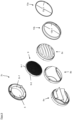
- an air outlet cover 8 designed as a blind 8a, as an air outlet nozzle 8b or as a ventilation grille 8c can be detachably attached to the mounting plate 2a according to the customer's choice and taking the local conditions into account.
- Three exemplary designs of air outlet covers 8 as they can be detachably attached to the mounting plate 2 using the air outlet cover holder 6b are shown in the Figures 5 to 7 .
- the mounting plate 2a can be covered with a star-shaped front panel 10a.
- the front panel holder 6d is designed such that the front panel 10a can be detachably attached to the front panel holder 6d.
- the Figure 1 The overview shown illustrates the modular structure of the wall box 1 and its versatility. Details of the Figure 1 The mounting plate 2a shown, which is the smallest construction unit of a modular wall box 1, are in the Figure 2 shown.
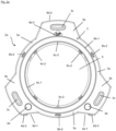
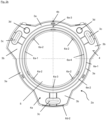
- the Figure 2 includes various views of the star-shaped mounting plate 2a.
- a plan view of the front 3 of the mounting plate 2a is shown in Figure 2a
- a top view of the back 4 of the mounting plate 2a is shown in Figure 2b
- a side sectional view of the mounting plate 2a is shown in Figure 2c
- a perspective view of the front side 3 of the mounting plate 2a in Figure 2d and a perspective view of the back 4 of the mounting plate 2a is shown in Figure 2e shown.
- the mounting plate 2a has a star shape in a top view of the front 3.
- the mounting plate 2a has three circular arc-shaped edge sections 3a, which are arranged rotationally symmetrically by 120° to the center of the air passage opening 5. Any two of the circular-arc-shaped edge sections 3a are connected by a further circular-arc-shaped wing section 3b, the outer edge of which describes the circular-arc shape having a larger radius than the edge sections 3a connected to it.
- the three wing sections 3b each have an elongated hole 3c through which a fastening means, for example a screw, can be passed to fasten the mounting plate 2a to a wall.
- Two of the wing sections 3b also each have a cable duct 3d connecting the front 3 and the back 4 of the mounting plate 2a, which can be broken out of the mounting plate 2a along a predetermined breaking point if necessary.
- the air outlet cover holder 6b arranged on the front side 3 has an annular web 6b-1 which is arranged concentrically to the air outlet opening 5.
- the air outlet cover holder 6b further comprises three locking lugs 6b-2.
- the three locking lugs 6b-2 are arranged radially on the outside of the annular web 6b-1 and at equidistant angular distances from one another and concentrically to the air passage opening 5.
- the ring-shaped web 6b-1 and the three locking lugs 6b-2 are designed in such a way that they can be brought into engagement with an adapter 7 that can be detachably attached to the air outlet cover holder 6b.
- the locking lugs 6b-2 engage in locking pockets 8a-2, 8b-2, 8c-2 provided for this purpose on the air outlet cover 8.
- the radially outer side surface of the ring-shaped web 6b-1 of the air outlet cover holder 6b is in engagement with a radially inner side wall section 8a-1, 8b-1, 8c-1 of an air outlet cover 8.
- the air outlet cover holder 6b further has an anti-twist device 6b-3, which is a projection that projects radially outward from the annular web 6b-1.
- the anti-twist device 6b-3 is designed in such a way that the projection can be brought into engagement with a corresponding recess 8a-3, 8b-3, 8c-3 provided in an air outlet cover 8.
- the anti-twist device 6b-3 is arranged centrally to the wing section 3b without the cable feedthrough 3d and on the side of the air passage opening 5 on which this wing section 3b without the cable feedthrough is also located.
- the insect screen holder 6c located on the front side 3 has an annular web 6c-1 which, in a plan view of the front side 3 of the mounting plate 2, is arranged concentrically to the air passage opening 5 and radially inwardly to the annular web 6b-1 of the air outlet cover holder 6b.
- the insect screen holder 6c also comprises a projection extending radially from the annular web 6c-1 in the direction of the center of the air passage opening 5, which acts as a rotation lock 6c-3 and prevents an unwanted rotation of a 6c detachably attached insect screen 9 prevents this.
- the projection of the anti-twist device 6c-3 is arranged centrally to the wing section 3b without cable feedthrough and on the side of the air passage opening 5 on which the wing section 3b without cable feedthrough is located.
- the projection of the anti-twist device 6c-3 of the insect screen holder 6c and the projection of the anti-twist device 6b-3 of the air outlet cover holder 6b are arranged in a line.
- the insect screen holder 6c is designed in such a way that the radially inner side surface of the annular web 6c-1 can be brought into engagement with a radially outer wall section 9-1 of an insect screen 9, while the locking lugs 6c-2 lock into locking pockets 9-2 provided in the insect screen 9.
- the projection of the anti-twist device 6c-3 engages in a corresponding recess 9-3 provided in the insect screen 9 and in this way prevents the insect screen 9 from accidentally twisting in the insect screen holder 6c.
- the insect screen 9 shown has essentially a circular shape and is designed such that the insect screen 9 can be detachably attached to the insect screen holder, wherein the insect screen 9 spans the air outlet opening 5 of the mounting plate 2a.
- the insect screen 9 has an integrated pollen filter, so that the insect screen 9 prevents both the penetration of insects and pests as well as the penetration of pollen into the air outlet opening of the mounting plate 2a.
- the insect screen 9 has a radially outer side wall section, locking pockets arranged on the radially outer side wall section and a recess.
- the radially outer side wall section is designed such that the radially outer side wall section can be brought into engagement with the radially inner side surface of the annular web 6c-1 of the insect screen holder 6c.
- the radially inner side surface of the annular web 6c-1 rests against the radially outer side wall section.
- the locking lugs 6c-2 of the insect screen holder are locked into the locking pockets, with the projection of the insect screen holder 6c acting as an anti-twist device 6c-3 engaging with the recess in the insect screen.
- the mounting plate 2a also has a front panel holder 6d.
- the front panel holder 6d is designed in such a way that a front panel 10, as shown by way of example in Figure 12, can be detachably attached to the front panel holder 6d.
- the front panel holder 6d has two locking pockets 6d-1.
- the locking pockets 6d-1 are arranged on the outer circumference of the wing section 3b, which have the cable ducts 3d. Adjacent to these two locking pockets 6d-1 is A radially outwardly projecting rib 6d-3 is arranged on each of the two ribs 6d-3.
- the ribs 6d-3 serve as a lever point for releasing a front panel 10 locked into the front panel holder 6d from the mounting plate 2a.
- the front panel holder 6d further has a locking pocket 6d-2, which is arranged diametrically opposite on the wing section 3b without a cable feedthrough.
- the locking pockets 6d-1 can be brought into engagement with locking lugs 10a-5 provided on the front panel 10a, while the locking pocket 6d-2 of the front panel holder 6d can be locked with a corresponding plurality of locking lugs 10a-6 arranged on the front panel 10a.
- the rear side 4 of the mounting plate 2a has an adapter holder 6a and a seal holder 6e.
- the adapter holder 6a is designed in such a way that an adapter 7 for connecting the air passage opening 5 to an air outlet pipe on the wall side (not shown in the figures) can be detachably fastened to the adapter holder 6a.
- the adapter holder 6a has two ring-shaped webs 6a-1 and 6a-4, which are arranged concentrically to each other and concentrically to the air passage opening 5.
- the radially inner web 6a-1 consists of three circular arc segments. An opening is arranged between every two adjacent circular arc segments.
- Radially inward to the outer web 6a-4, the adapter holder 6a has four locking pockets 6a-2.
- the locking pockets 6a-2 are evenly distributed at equidistant angular intervals along the web 6a-4.
- the adapter holder 6a has a projection that acts as an anti-twist device 6a-3 and extends from the radially inner web 6a-1 in the direction of the center of the air passage opening 5.
- the projection is arranged centrally and on the side of the air passage opening 5 of the wing section 3b without a cable feedthrough.
- the ring-shaped webs 6a-1 and 6a-4, the locking pockets 6a-2 and the anti-twist device 6a-3 are designed in such a way that an adapter 7 can be detachably attached to the adapter holder 6a.
- the radially inner side surface of the outer web 6a-4 rests against a correspondingly designed, radially outer wall section 7a-1 of the adapter 7a, 7b.
- the locking pockets 6a-2 are locked with locking lugs 7a-2, 7b-2 arranged accordingly on the adapter 7a, 7b, while the projection acting as an anti-twist device 6a-3 engages in a corresponding recess 7a-3, 7b-3 provided on the adapter 7a, 7b.
- Two versions of a correspondingly designed adapter 7a, 7b are shown in the Figures 3 and 4 shown.
- the back 4 of the mounting plate 2a also has a plurality of recesses 4a, which are designed in such a way that insulating material can be introduced into the recesses 4a. Insulating material introduced into the recesses 4a before the mounting plate 2a is mounted on a wall helps to prevent the formation of thermal bridges.
- the seal holder 6e which is also arranged on the rear side 4, is designed such that a seal 12 can be detachably attached to the seal holder 6e.
- the seal holder 6e has an annular web 6e-1, which is arranged radially outwardly to the outer web 6a-4 of the adapter holder 6a and concentrically to the air passage opening 5.
- the annular web 6e-1 of the seal holder 6e and the outer web 6a-4 of the adapter holder 6a together form a groove 6e-2.
- the groove 6e-2 is designed such that a seal can be inserted into the groove 6e-2 in a force-fitting manner.
- the annular web 6e-1 of the seal holder 6e and the outer web 6a-4 of the adapter holder are connected to one another by a connecting web 6e-3.
- the connecting web 6e-3 interrupts the otherwise annular groove 6e-2 and serves as a drip edge. Moisture collecting on the seal holder 6e can drip along the drip edge and flow off through an opening 4b in the mounting plate 2a arranged below the connecting web 6e-3.
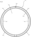
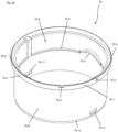
- FIG. 3a An embodiment of an adapter 7b which can be detachably attached to the adapter holder 6a is shown in the Figures 3a to 3e shown, where the Figures 3a to 3e five views of the exemplary adapter 7b.
- a top view of the air outlet opening 7b-5 of the adapter 7b is shown in the Figure 3a , a plan view of the air inlet opening 7b-4 in the Figure 3b , a longitudinal section through the pipe section 7b-6 in the Figure 3c , a perspective view of the air outlet opening 7b-5 in the Figure 3d and a perspective view of the air inlet opening 7b-4 in the Figure 3e shown.
- the adapter 7b shown has an air inlet opening 7b-4, an air outlet opening 7b-5 and a pipe section 7b-6 connecting the air inlet opening 7b-4 and the air outlet opening 7b-5.
- the adapter 7b is designed such that it can be detachably fastened to the adapter holder 6a such that the air outlet opening 7b-5 is connected to the air passage opening 5 of the mounting plate 2a for the flow of gas.
- the pipe section 7b-6 has a circumferential collar 7b-7 at its free end with the air outlet opening 7b-5.
- the circumferential collar 7b-7 is designed such that an outer wall section 7b-1 of the collar 7b-7 can be brought into engagement with the radially inner side surface of the outer annular web 6a-4 of the adapter holder 6a.
- the collar 7b-7 has four locking lugs 7b-2, which are arranged at equidistant intervals around the air outlet opening 7b-5 in such a way that the locking lugs 7b-2 can be locked into the locking pockets 6a-2 of the adapter holder 6a.
- the anti-twist device 6a-3 also engages. acting projection of the adapter holder 6a in a recess 7b-3 provided for this purpose on the collar 7b-7 of the adapter 7b.
- the outer cross-section of the pipe section 7b-6 extending axially from the collar 7b-7 in the direction of the air inlet opening 7b-4 is designed in such a way that it is flush with the inner surface of a wall-side ventilation pipe in a radial manner.
- the outer edge of the pipe section 7b-6 enclosing the air inlet opening 7b-4 has a bevel that allows it to be easily inserted into a wall-side ventilation pipe.
- the radial width of the collar 7b-7 determines the outer diameter of the pipe section 7b-6.
- the collar 7b-7 of the Figure 3 The adapter 7b shown has a smaller radial width than the collar of the Figure 1 shown adapter 7a.
- the adapter 7a with the wider collar is used to connect a wall-side ventilation pipe with a smaller inner diameter.
- the adapter 7b with the narrower collar compared to the adapter 7a is used to connect a wall-side ventilation pipe with a correspondingly larger inner diameter.
- the outer diameter of the collars 7b-7 is the same for both adapters 7a, 7b, so that they can both be brought into engagement with the adapter holder 6a of the mounting plate 2a.
- the adapters 7a, 7b are further designed in such a way that a flap insert 14 can be inserted into the adapter 7a, 7b.
- the pipe section 7b-6 has an insertion stop 7b-8 on its inside in the form of a radially circumferential web with two diametrically opposed curved sections 7b-9 curved in the axial direction.
- the curved sections 7b-9 form an axial boundary of recesses 7b-10 arranged in the side wall of the pipe section 7b-6 and extending in the axial direction from the curved section 7b-9 in the direction of the air inlet opening 7b-4.
- the end of the pipe section 7b-6 with the air inlet opening 7b-4 has two diametrically opposed locking pockets 7b-11.
- the locking pockets 7b-11 are designed in such a way that they can be brought into engagement with locking lugs 14b-1 provided in a flap insert 14.
- An exemplary embodiment of a flap insert 14b is shown in the Figure 4 shown.
- the Figures 4a to 4c include various views of a flap insert 14a with a self-falling ventilation flap, wherein the Figure 4a a perspective view of the air outlet opening 14a-3 of the flap insert 14a without ventilation flap, the Figure 4b a perspective view of the air inlet opening 14a-2 of the flap insert 14a without ventilation flap and the Figure 4c a perspective view of the flap insert 14 with a ventilation flap 14a-5.
- the flap insert 14a has an air inlet opening 14a-2 and an air outlet opening 14a-3 as well as a pipe section 14a-4 that connects the air inlet opening 14a-2 and the air outlet opening 14a-3.
- a ventilation flap 14a-5 (only in the Figure 4c shown).
- the ventilation flap 14a-5 is suspended from the pipe section 14a-4 in a self-falling manner such that the ventilation flap 14a-5 can be pushed open in one flow direction by a sufficiently strong air flow through the pipe section 14a-4. If the ventilation flow decreases, the ventilation flap 14a-5 falls back to its original position due to the gravitational force acting on it.
- the inner cross section of the pipe section 14a-4 is closed by the ventilation flap 14a-5.
- a stop 14a-9 on the inner side wall of the pipe section 14a-4 prevents the ventilation flap 14a-5 from being pushed open by an air flow from the correspondingly other flow direction.
- the ventilation flap 14a-5 has a magnetic closure 14a-8 on its lower, outer edge section.
- the weight of the magnet also encourages the ventilation flap 14a-5 to close due to the force of gravity.
- a magnetic material 14a-10 arranged opposite on the inside of the pipe section 14a-4 can, together with the magnet, further encourage the ventilation flap 14a-5 to close.
- the axis of rotation of the ventilation flap 14a-5 opens into recesses 14a-7 on both sides, which are arranged in the outer wall of the pipe section 14a-4.
- the recesses 14a-7 merge into arcuate projections 14a-6, which extend in the axial direction.
- the arcuate projections 14a-6 are designed in such a way that they can be brought into engagement with the arcuate sections 7a-9, 7b-9 of an adapter 7.
- the pipe section 14a-4 Arranged at a 90° offset from the recesses 14a-7 in the circumferential direction, the pipe section 14a-4 has two diametrically opposed locking lugs 14a-1 on its outside at its end with the air inlet opening 14a-2. If the flap insert 14a is inserted into an adapter 7b, the locking lugs 14a-1 engage in the locking pockets 7b-11 of the adapter 7b. The end of the pipe section 14a-4 with the air outlet opening 14a-3 and the curved projections 14a-6 engages with the insertion stop 7b-8 and the curved sections 7b-9. The air outlet opening 14a-3 is aligned with the air outlet opening 7b-5 of the adapter 7b.
- the air inlet opening 14a-2 of the flap insert 14a is aligned with the air inlet opening 7b-4 of the adapter 7b.
- the pipe section 14a-4 of the flap insert 14a rests with its outer surface on the inner surface of the pipe section 7b-6 of the adapter 7b.
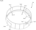
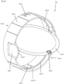
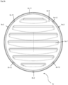
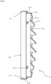
- FIGS. 5a to 7e show three exemplary embodiments of air outlet panels 8, as they can be detachably fastened to the mounting plate 2a with the air outlet panel holder 6c.
- FIGS. 5a to 5e show five views of an air outlet panel 8 designed as a ventilation grille 8c.
- Figure 5a shows a plan view of the front of the ventilation grille 8c
- Figure 5b a top view of the back of the ventilation grille 8c
- Figure 5c a side sectional view of the ventilation grille 8c
- Figure 5d a perspective view of the front of the ventilation grille 8c
- Figure 5e a perspective view of the back of the ventilation grille 8c.
- the Figures 6a - 6e show an air outlet panel 8 designed as an air outlet nozzle 8b and also include five views.
- the five views are a plan view of the front in Figure 6a , a top view of the back in Figure 6b , a lateral sectional view in Figure 6c , a perspective view of the front in Figure 6d and a perspective view of the back in Figure 6e .
- the Figures 7a - 7e show an air outlet panel 8 designed as a blind 8a and include five views.
- the five views are a plan view of the front in the Figure 7a , a side view from above in the Figure 7b , a side view from the side in the Figure 7c , a perspective view of the front of the blind with closed slats in the Figure 7d and a perspective view of the front of the blind with open slats in the Figure 7e .
- the air outlet cover 8 whether designed as a ventilation grille 8c, as a blind 8a or as an air outlet nozzle 8b, has an air outlet opening 8a-5, 8b-5, 8c-5, an air inlet opening 8a-4, 8b-4, 8c-4 and a fastening ring 8a-6, 8b-6, 8c-6 connecting the air outlet opening 8a-5, 8b-5, 8c-5 and the air inlet opening 8a-4, 8b-4, 8c-4.
- the fastening ring 8a-6, 8b-6, 8c-6 has a radially inner side wall section 8a-1, 8b-1, 8c-1 and three equidistantly spaced locking pockets 8a-2, 8b-2 8c-2 as well as a recess 8a-3, 8b-3, 8c-3.
- the radially inner side wall section 8a-1, 8b-1, 8c-1 can be brought into engagement with the radially outer side surface of the annular web 6b-1 of the air outlet cover holder 6b.
- the locking pockets 8a-2, 8b-2, 8c-2 can be brought into engagement with the locking lugs 6b-2 arranged accordingly on the air outlet cover holder 6b.
- the recess 8a-3, 8b-3, 8c-3 of the fastening ring 8a-6, 8b-6, 8c-6 can be brought into engagement with the projection 6b3 which acts as an anti-twist device.
- a cover 8a-9, 8b-9, 8c-9 which at least partially covers the air outlet opening 8a-5, 8b-5, 8c-5, adjoins the fastening ring 8a-6, 8b-6, 8c-6 axially in the direction of the air outlet opening 8a-5, 8b-5, 8c-5.
- the transition between cover 8a-9, 8b-9, 8c-9 and fastening ring 8a-6, 8b-6, 8c6 is stepped.
- the air outlet panel 8a, 8b, 8c further has a design element holder 8a-10, 8b-10, 8c-10 with an annular wall section 8a-11, 8b-11, 8c-11.
- annular wall section 8a-11, 8b-11, 8c-11 four locking pockets 8a-12, 8b-12, 8c-12 are set along the circumference of the annular wall section 8a-11, 8b-11, 8c-11 at equidistant intervals from one another.
- the locking pockets 8a-12, 8b-12, 8c-12 are designed such that the locking pockets 8a-12, 8b-12, 8c-12 can be brought into engagement with locking lugs 13a-1, 13b-1 arranged accordingly on a design element 13.
- the ventilation grille 8c, the blind 8a and the air outlet nozzle 8b differ only in the further design of the cover 8a-9, 8b-9, 8c-9 which at least partially covers the air outlet opening 8a-5, 8b-5, 8c-5.
- the ventilation grille 8c has a plurality of air baffles 8c-7 extending transversely across the air outlet opening 8c-5.
- the air outlet nozzle 8b has a hood 8b-7 extending over the air outlet opening 8c-5 with three openings 8b-8.
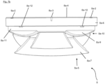
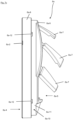
- the blind 8a has three slats 8a-7 extending across the air outlet opening 8a-5.
- the slats 8a-7 are arranged vertically one above the other and have an approximately trapezoidal shape when viewed from above.
- the slats 8a-7 can be pivoted between a state in which the air outlet opening 8a-5 is closed and a state in which the air outlet opening 8a-5 is partially exposed. In their closed state, they completely cover the openings 8a-8 arranged in the panel 8a-9 under the slats 8a-7.
- FIGS 8a and 8b an embodiment of a front panel 10a is shown, as in accordance with the Figure 1 can be detachably attached to the front panel holder 6d.
- the Figures 8a and 8b comprise two views, namely a perspective view of the front of a front panel 10a in Figure 8a and a perspective view of the back of the front panel 10a in Figure 8b .
- the front panel 10a has an upper shell 10a-1 with a centrally arranged circular opening 10a-2. In a top view of the upper shell 10a-1, this has a star-shaped contour. Starting from the centrally arranged circular opening 10a-2, the front panel 10a has three circular-arc-shaped edge sections 10a-3, which are arranged rotationally symmetrically by 120° to the center of the circular opening 10a-2. Two of the circular-arc-shaped edge sections 10a-3 are connected by a further circular-arc-shaped wing section 10a-4, the outer edge of which describes the circular arc shape having a larger radius than the edge sections 10a-3 connected to it.
- a locking lug 10a-5 is arranged on the outer circumference of each of two wing sections 10a-4 and a plurality of locking lugs 10a-6 are arranged on the outer circumference of the third wing section 10a-4.
- the locking lugs 10a-4 can be brought into engagement with the locking pockets 6d-1 of the front panel holder and the plurality of locking lugs 10a-5 can be brought into engagement with the locking pocket 6d-2.
- the upper shell 10a-1 covers the mounting plate 2a in such a way that the circular opening 10c-2 leaves the air outlet opening 8a-5, 8b-5, 8c-5 of the mounting plate 2a with the air outlet panel holder 6d free.
- FIG. 9 a modular wall box 1 with a mounting plate 2c is shown.
- the mounting plate 2c has a front side 3 and a back side 4 as well as an air passage opening 5 connecting the front side 3 to the back side 4.
- the mounting plate 2c is circular in a plan view of its front side, with the mounting plate 2c having an insect screen holder 6c and an air outlet cover holder 6b on its front side 3.
- the insect screen holder 6c is designed such that an insect screen 9 can be detachably attached to the insect screen holder 6c.
- the air outlet cover holder 6b is designed such that an air outlet cover 8a, 8b, 8c can be detachably attached to the air outlet cover holder.
- the insect screen holder 6c and the air outlet cover holder 6b are made of the same material as the insect screen holder 6c and the air outlet cover holder 6b of the mounting plate 2a.
- Figures 1 and 2 In this respect, the mounting plate 2c can be combined with the insect screen 9 and the air outlet covers 8a, 8b, 8c, as described in connection with the previous figures.
- the two in the Figure 9 The embodiments of a design element 13a, 13b shown consist of a ring with four locking lugs 13a-1, 13b-1 arranged at equidistant intervals from one another along its inner circumference.
- the locking lugs 13a-1, 13b-1 are designed in such a way that the locking lugs 13a-1, 13b-1 can be brought into engagement with locking pockets 8a-12, 8b-12, 8c-12 provided correspondingly on the air outlet panels 8.
- the design element 13a, 13b is detachably fastened to an air outlet panel 8
- the locking lugs 13a-1, 13b-1 engage in the locking pockets 8a-12, 8b-12, 8c-12 of the air outlet panel 8.
- the ring-shaped design element 13a, 13b is arranged concentrically to the air outlet opening of the air outlet cover 8.
- an air outlet pipe holder is arranged, which, unlike the mounting plate 2a, is designed according to the Figures 1 and 2 is not designed as an adapter holder 6b.
- the air outlet pipe holder is a pipe section 2c-1 formed on the mounting plate, which is connected to the air passage opening 5.
- the pipe section 2c-1 is designed in such a way that it can be detachably fastened to an air outlet pipe on the wall side.
- FIG 10 a further embodiment of a mounting plate 2b according to the invention for a modular wall box 1 is shown.
- the mounting plate 2b has a front side 3, a back side 4 and an air passage opening 5 connecting the front side 3 and the back side 4.
- the mounting plate 2b is circular, with the air passage opening 5 arranged in the middle.
- Three elongated holes 3c are arranged at equidistant angular intervals around the air passage opening 5.
- the mounting plate 2b of the Figure 10 on its rear side 4 an air outlet pipe holder designed as an adapter holder 6a and a seal holder 6e.
- the mounting plate 2b On the front side 3, the mounting plate 2b also has an insect screen holder 6c, an air outlet panel holder 6b and a front panel holder 6d.
- the adapter holder 6b, the seal holder 6e, the insect screen holder 6c and the adapter holder 6b are as in the mounting plate 2a according to the embodiment of the Figures 1 and 2 designed.
- the front panel mount 6d of the mounting plate 2b of the Figure 10 designed in such a way that the Figure 10 shown front panels 10c, 10b can be detachably attached to the front panel holder 6d.
- the front panels 10c, 10b are circular or rectangular in a plan view of their front side.
- the front panels 10c, 10b and the front panel holder 6d have fastening means that complement each other, as were also described in connection with the star-shaped mounting plate 2a and the star-shaped front panel 10a. Only the exact positioning of the fastening means is adapted to the rectangular or circular design of the front panels 10c, 10b and the circular shape of the mounting plate 2c.
Landscapes
- Engineering & Computer Science (AREA)
- Chemical & Material Sciences (AREA)
- Combustion & Propulsion (AREA)
- Mechanical Engineering (AREA)
- General Engineering & Computer Science (AREA)
- Air-Flow Control Members (AREA)
- Ventilation (AREA)
Description
- Die vorliegende Erfindung betrifft eine Montageplatte für einen modularen Mauerkasten, wobei die Montageplatte eine Vorderseite, eine Rückseite und eine die Vorderseite und die Rückseite verbindende Luftdurchtrittsöffnung aufweist.
- Zur Verbesserung des Raumklimas in Räumen, insbesondere im Wohnbereich, z. B. in Küche oder Bad, dienen Mauerkästen einem Luftaustausch. "Verbrauchte" Luft wird durch eine Luftdurchtrittsöffnung in dem Mauerkasten aus dem Inneren eines Gebäudes nach Außen abgeführt, während "frische" Luft durch die Luftdurchtrittsöffnung in den Raum gelangt. Ein Mauerkasten weist einen mit einer Montageplatte verbundenen Rohrabschnitt auf. Der Rohrabschnitt ist mit einem mauerseitigen Luftausrittsrohr verbindbar oder zumindest in eine Bohrung in der Wand, an der die Montageplatte befestigt werden soll, einbringbar, wobei der Rohrabschnitt selbst mit der Luftdurchtrittsöffnung in der Montageplatte verbunden ist. Da die Montageplatte auch der Befestigung des Mauerkastens dient, ist die Rückseite der Montageplatte dementsprechend der Wand des Raumes, durch die der Luftaustausch erfolgen soll, zugewandt. Die Vorderseite der Montageplatte ist gegenüberliegend zu der Rückseite angeordnet.
- Neben der grundlegenden Funktion eines Mauerkastens einen Luftaustausch zu ermöglichen, sollen Mauerkästen weitere, damit im Zusammenhang stehende Funktionen erfüllen. So sollen häufig ein ungewollter Wärmeverlust, das Entstehen eines ungewollten Luftzugs, ein Eindringen von Staub, Insekten oder allgemein Schädlingen durch den Mauerkasten verhindert werden, oder die Strömungseigenschaften durch den Mauerkasten einstellbar sein. Welche Funktionen des Mauerkastens im Einzelfall im Vordergrund stehen, hängt von den örtlichen Gegebenheiten am Einsatzort und auch von den Kundenwünschen ab. Damit ein herkömmlicher Mauerkasten, die jeweiligen Funktionen zufriedenstellend erfüllen kann, bedarf es bisher zahlreiche Ausführungen von Mauerkästen, die jeweils auf eine spezielle Funktion abgestimmt und einstückig hergestellt sind.
- Besteht die Notwendigkeit die Funktion eines Mauerkastens zu ändern oder dem Mauerkasten eine weitere Funktion hinzuzufügen, ist es bisher erforderlich, den Mauerkasten durch einen anderen Mauerkasten zu ersetzen, der besser auf die geänderten Anforderungen abgestimmt ist. Die Bereitstellung einer Vielzahl von Mauerkästen, die jeweils für eine spezielle Funktion ausgelegt sind, ist jedoch teuer und aufwendig.
- Die deutsche Patentanmeldung
DE 26 06 011 A1 betrifft eine Anschlussvorrichtung für Abluftrohre mit einem Rahmen. Mit dem Rahmen kann wahlweise ein Gittereinsatz oder eine Rückstauklappe verbunden werden. - Die US-Patentschrift
US 5,791,985 A betrifft einen Mauerkasten mit einer Montageplatte, wobei an der Montageplatte eine Abdeckhaube sowie ein Insektengitter befestigbar ist. - Die US-Patentanmeldungen
US 2005/0202778 A1 undUS 2010/0159821 A1 betreffen ebenfalls jeweils einen Mauerkasten mit einer Montageplatte. Die Komponenten des Mauerkastens sind kaskadierend miteinander verbunden. Dabei offenbart dieUS 2005/0202778 A1 einen Mauerkasten gemäß dem Oberbegriff von Anspruch 1. - Die US-Patentanmeldung
US 2009/0081942 A1 betrifft einen Mauerkasten mit einer Montageplatte, wobei an der Montageplatte eine Lüftungsklappe und eine Abdeckhaube sowie ein Anschlussrohr befestigbar sind. - Es besteht daher ein Bedarf an einem Mauerkasten, dessen Funktionen möglichst individuell zusammenstellbar sowie an die örtlichen Gegebenheiten und die einzelnen Kundenwünschen anpassbar sind.
- Zumindest eine dieser Aufgaben wird gemäß der vorliegenden Erfindung durch einen modularen Mauerkasten mit den Merkmalen von Anspruch 1 gelöst, wobei der Mauerkasten eine Montageplatte, eine eine Luftdurchtrittsöffnung der Montageplatte zumindest teilweise abdeckende Luftaustrittsblende und eine eine Vorderseite der Montageplatte zumindest teilweise verdeckenden Frontblende aufweist, wobei die Montageplatte eine Frontblendenaufnahme aufweist, wobei die Frontblende lösbar an der Frontblendenaufnahme befestigt ist, wobei die Frontblendenaufnahme und die Frontblende zueinander komplementäre Befestigungsmittel aufweisen, die lösbar miteinander in Eingriff sind, wobei die Montageplatte die Vorderseite, eine Rückseite und eine die Vorderseite und die Rückseite verbindende Luftdurchtrittsöffnung aufweist, wobei auf der Rückseite der Montageplatte zumindest eine Luftaustrittsrohraufnahme angeordnet ist, die derart ausgestaltet ist, dass ein mauerseitiges Luftaustrittsrohr lösbar an der Luftaustrittsrohraufnahme der Montageplatte befestigbar ist, wobei der Mauerkasten einen Adapter zum Verbinden der Luftdurchtrittsöffnung der Montageplatte mit einem mauerseitigen Luftaustrittsrohr oder einem Mauerdurchbruch aufweist, wobei die Luftaustrittsrohraufnahme eine Adapteraufnahme ist, wobei der Adapter lösbar an der Adapteraufnahme befestigt ist, wobei die Adapteraufnahme und der Adapter zueinander komplementäre Befestigungsmittel aufweisen, die lösbar miteinander in Eingriff sind, wobei die Vorderseite der Montageplatte zumindest eine Luftaustrittsblendenaufnahme aufweist, wobei die Luftaustrittsblende lösbar an der Luftaustrittsblendenaufnahme befestigt ist und wobei die Luftaustrittsblendenaufnahme und die Luftaustrittsblende zueinander komplementäre Befestigungsmittel aufweisen, die lösbar miteinander in Eingriff sind. Bevorzugte Ausgestaltungen der Erfindung sind in den abhängigen Ansprüchen definiert.
- Die erfindungsgemäß ausgestaltete Montageplatte ist das Grundelement für einen modularen Mauerkasten. Der modulare Aufbau des Mauerkastens ermöglicht es, dass einzelne Komponenten des Mauerkastens durch ein Verbinden mit oder Lösen von der Montageplatte hinzugefügt, ersetzt oder entfernt werden können. Die Montageplatte kann auf diese Weise, nach Art eines Baukastensystems, für den Aufbau einer Vielzahl von Mauerkästen verwendet werden, deren einzelnen Komponenten sich unterscheiden und auf die örtlichen Gegebenheiten sowie die Kundenwünsche abgestimmt sind.
- Im Sinne der vorliegenden Erfindung umfasst der Begriff "lösbar befestigbar" mechanische Verbindungen, die durch einen Form- und/oder Kraftschluss bewirkt werden. Insbesondere Klebe- oder Schweißverbindungen sind im Sinne der vorliegenden Erfindung nicht "lösbar".
- Die im Kontext der vorliegenden Erfindung verwendeten Begriffe "Luftdurchtrittsöffnung", "Lufteintrittsöffnung" und "Luftaustrittsöffnung" beschränken nicht die Strömungsrichtungen durch die jeweilige Öffnung, sondern werden einzig zur besseren Unterscheidbarkeit der verschiedenen Öffnungen verwendet.
- Im montierten Zustand ist die Rückseite der Montageplatte in der Regel einer Wand oder Mauer zugewandt, durch die der Luftaustausch erfolgen soll.
- Die auf der Rückseite der Montageplatte angeordnete Luftaustrittsrohraufnahme ist derart ausgestaltet, dass ein mauerseitiges Luftaustrittsrohr lösbar an der Luftaustrittsrohraufnahme befestigbar ist.
- Die auf der Vorderseite der Montageplatte angeordnete Luftaustrittsblendenaufnahme ist derart ausgestaltet, dass eine die Luftdurchtrittsöffnung zumindest teilweise abdeckende Luftaustrittsblende lösbar an der Luftaustrittsblendenaufnahme befestigt ist. Im Sinne der vorliegenden Erfindung ist eine Luftaustrittsblende zunächst eine die Luftdurchtrittsöffnung zumindest teilweise abdeckende Blende, die ggf. geeignet ist, die Hauptströmungsrichtung eines durch die Luftdurchtrittsöffnung durchströmenden Luftstroms zu verändern. Insofern weist eine Luftaustrittsblende in einer Ausführungsform sich zumindest teilweise über die Luftdurchtrittsöffnung erstreckende Luftleitlemente auf.
- Dementsprechend ist an der Montageplatte eine Luftaustrittsblende lösbar befestigt. Die lösbare Befestigung ermöglicht es, dass die Luftaustrittsblendenaufnahme mit einer Vielzahl von verschiedenen ausgestalteten Luftaustrittsblenden und die Luftaustrittsrohraufnahme mit einer Vielzahl von verschieden ausgestalteten Luftaustrittsrohren verwendbar ist. Welche Luftaustrittsblende und welches Luftaustrittsrohr an der Montageplatte zur Gestaltung des Mauerkastens befestigt werden sollen, kann in Abhängigkeit von den Kundenvorgaben und den Voraussetzungen am Montageort entschieden werden. Eine Vorratshaltung von vorkonfektionierten Mauerkästen kann so vermieden werden.
- Die Luftaustrittsblendenaufnahme weist Befestigungsmittel auf, wobei die Befestigungsmittel derart ausgestaltet sind, dass die Luftaustrittsblende mit den Befestigungsmittel der Luftaustrittsblendenaufnahme lösbar befestigt ist, vorzugsweise weisen die Befestigungsmittel Rastmittel und/oder ein Schraubgewinde auf.
- Die Luftaustrittsblende und die Luftaustrittsblendenaufnahme weisen Befestigungsmittel auf, wobei die Befestigungsmittel derart komplementär zueinander ausgestaltet sind, dass die Befestigungsmittel der Luftaustrittsblende und die Befestigungsmittel der Luftaustrittsblendenaufnahme lösbar miteinander in Eingriff sind.
- Die Luftaustrittsrohraufnahme ist eine Adapteraufnahme, die derart ausgestaltet ist, dass ein Adapter zum Verbinden der Luftdurchtrittsöffnung der Montageplatte mit einem mauerseitigen Luftaustrittsrohr oder einem Mauerdurchbruch lösbar an der Adapteraufnahme befestigt ist.
- Im Sinne der vorliegenden Erfindung ist ein Adapter ein Übergangstück, welches jeweils sowohl mit dem mauerseitigen Luftaustrittsrohr oder an einem Mauerdurchbruch als auch an der Montageplatte lösbar zum Durchleiten eines Luftstroms durch die Luftdurchtrittsöffnung der Montageplatte befestigbar ist. Insofern wird der Adapter zur Inbetriebnahme des Mauerkastens mit dem mauerseitigen Luftaustrittsrohr und mit der Adapteraufnahme auf der Rückseite der Montageplatte lösbar verbunden.
- Dabei weisen der Adapter und die Adapteraufnahme der Montageplatte miteinander in Eingriff befindliche, zueinander komplementäre Befestigungsmittel zum lösbaren Befestigen des Adapters in der Adapteraufnahme auf, wobei vorzugsweise die Befestigungsmittel Rastmittel und/oder ein Schraubgewinde aufweisen.
- Ferner weist die Montageplatte eine Frontblendenaufnahme auf, wobei die Frontblendenaufnahme derart ausgestaltet ist, dass eine die Vorderseite der Montageplatte zumindest teilweise verdeckende Frontblende lösbar an der Frontblendenaufnahme befestigt ist. Vorzugsweise ist die Frontblendenaufnahme auf der Vorderseite der Montageplatte angeordnet.
- Dabei weist die Frontblendenaufnahme Befestigungsmittel auf, die derart ausgestaltet sind, dass mit den Befestigungsmitteln eine Frontblende lösbar an der Frontblendenaufnahme befestigt ist. Vorzugsweise sind die Befestigungsmittel Rastmittel. Die Frontblende und die Frontblendenaufnahme weisen zueinander komplementäre Befestigungsmittel zum lösbaren miteinander in Eingriff bringen auf, wobei die Befestigungsmittel vorzugsweise zueinander komplementäre Rastmittel und/oder komplementäre Schraubgewinde aufweisen.
- Im Sinne der vorliegenden Erfindung ist eine Frontblende zunächst eine Komponente eines Mauerkastens, die in einem Zustand, in dem die Frontblende mit der Frontblendenaufnahme lösbar durch die Frontblendenaufnahme an der Montageplatte befestigt ist, zumindest teilweise die Vorderseite der Montageplatte überdeckt. Eine an der Frontblendenaufnahme befestigte Frontblende schützt die Montageplatte sowie die unter der Frontblende angeordneten Komponenten vor Umwelteinflüssen und bildet einen frontseitigen Abschluss des Mauerkastens.
- In einer Ausführungsform weist die Montageplatte auf ihrer Rückseite eine Dichtungsaufnahme auf, wobei die Dichtungsaufnahme derart ausgestaltet ist, dass eine Dichtung lösbar an der Dichtungsaufnahme an der Montageplatte befestigbar ist.
- Eine an der Dichtungsaufnahme lösbar befestigte Dichtung verhindert, dass Luft und/oder Feuchtigkeit zwischen der Montageplatte und einer Mauer, an der die Montageplatte in einem montierten Zustand angeordnet ist, in den Mauerkasten eindringt.
- In einer Ausführungsform weist die Montageplatte auf ihrer Vorderseite eine Insektengitteraufnahme auf, wobei die Insektengitteraufnahme derart ausgestaltet ist, dass ein Insektengitter lösbar an der Insektengitteraufnahme befestigbar ist.
- Im Sinne der vorliegenden Erfindung umfasst der Begriff "Insektengitter" einen sich über die Luftdurchtrittsöffnung erstreckendes Gitter, welches lösbar an der Insektengitteraufnahme befestigbar ist und ein Eindringen von Insekten, Schädlingen und/oder Pollen durch die Luftdurchtrittsöffnung der Montageplatte verhindert. Das Insektengitter verhindert somit, dass Insekten und/oder Schädlinge durch die Luftdurchtrittsöffnung in einen mit dem modularen Mauerkasten belüften Raum gelangen.
- Jede im Zusammenhang mit bestimmten Ausführungsformen der Montageplatte beschriebene Aufnahme ist unabhängig von dem Vorhandensein anderer/weiterer an der Montageplatte angeordneten Aufnahmen offenbart. Es versteht sich, dass das Vorhandensein einer lösbar an einer Aufnahme befestigte Komponente im Sinne der vorliegenden Erfindung eine entsprechend ausgestaltete Aufnahme erfordert. Das Vorhandensein einer an der Montageplatte angeordneten Aufnahme erfordert anderseits nicht, dass eine Komponente lösbar mit dieser Aufnahme befestigt ist.
- Insofern kann die Montageplatte in einer Ausführungsform auf ihrer Vorderseite zusätzlich zu der Luftaustrittsblendenaufnahme eine Insektengitteraufnahme und auf ihrer Rückseite zusätzlich zu der Luftaustrittsrohraufnahme in Form einer Adapteraufnahme eine Dichtungselementaufnahme aufweisen. Die Frontblendenaufnahme kann auch an einer Seitenfläche der Montageplatte angeordnet sein.
- In einer Ausführungsform ist die Montageplatte in einer Draufsicht auf ihre Vorderseite mit Bezug auf den Mittelpunkt der Luftdurchtrittsöffnung rotationssymmetrisch.
- In einer Ausführungsform hat die Montageplatte in einer Draufsicht auf ihre Vorderseite eine kreisförmige, eine rechteckige, eine sternförmige oder eine im Wesentlichen dreieckige Außenkontur.
- In einer Ausführungsform hat die Montageplatte in einer Draufsicht auf ihre Vorderseite eine sternförmige, im Wesentlichen dreieckige Außenkontur, wobei ausgehend von einer mittig angeordneten, kreisförmigen Luftdurchtrittsöffnung, die die Vorderseite mit der Rückseite verbindet, die Montageplatte mehrere, vorzugsweise drei kreisbogenförmige, Randabschnitte aufweist, die gleichmäßig, vorzugsweise um 120° rotationssymmetrisch, zu dem Mittelpunkt der Luftdurchtrittsöffnung angeordnet sind. Je zwei der Randabschnitte sind durch einen weiteren Flügelabschnitt, der vorzugsweise kreisbogenförmig ist, verbunden. Der die Kreisbogenform beschreibende äußere Rand des Flügelabschnitts hat einen größeren Radius als die mit ihm verbundenen Randabschnitte.
- In einer Ausführungsform weist die Montageplatte Befestigungsmittel auf, wobei die Befestigungsmittel derart ausgestaltet sind, dass die Montageplatte mit den Befestigungsmitteln an einer Wand befestigbar ist. In einer Ausführungsform weist die Montageplatte Durchbrechungen, vorzugsweise Langlöcher, zum abschnittsweisen Hindurchführen von Befestigungsmitteln, vorzugsweise Schrauben, auf.
- In einer Ausführungsform sind die Durchbrechungen, vorzugsweise Langlöcher, in äquidistanten Abständen um die Luftdurchtrittsöffnung herum angeordnet. Hat die Montageplatte in einer Draufsicht auf die Montageplatte eine sternförmige Außenkontur, so weist vorzugsweise jeder Flügelabschnitt eine Durchbrechung auf.
- In einer Ausführungsform weist die Montageplatte zusätzlich zu der Luftdurchtrittsöffnung zumindest eine die Vorderseite und die Rückseite der Montageplatte verbindende Kabeldurchführung auf. Durch die Kabeldurchführung können Kabel für den Anschluss elektrischer Bauteile durch die Montageplatte hindurchgeführt werden. Beispielsweise kann ein frontseitig an dem Mauerkasten angeordnetes Leuchtmittel mit einem durch die Kabeldurchführung hindurchgeführtes Kabel elektrisch an eine Stromversorgung angeschlossen werden. In einer Ausführungsform kann ein nachstehend beschriebes Designelement ein Leuchtmittel aufweisen, welches mit einem durch die Kabeldurchführung hindurchführbaren Kabel an eine Stromversorgung anschließbar ist.
- In einer Ausführungsform ist die Kabeldurchführung entlang einer geschlossenen Sollbruchlinie aus dem Material der Montageplatte herausbrechbar. Eine auf diese Weise an der Montageplatte vorgesehene Kabeldurchführung ist zunächst verschlossen. Wird die Kabeldurchführung benötigt, kann das die Kabeldurchführung verdeckende Material der Montageplatte entlang der Sollbruchlinie entfernt und so die Kabeldurchführung verwendbar gemacht werden. Hat die Montageplatte in einer Ausführungsform in einer Draufsicht auf ihre Vorderseite eine sternförmige Außenkontur mit drei Flügelabschnitten, so weisen vorzugsweise zwei der Flügelabschnitte je eine die Vorderseite und die Rückseite der Montageplatte verbindende Kabeldurchführung auf.
- In einer Ausführungsform weist die Rückseite und/oder die Vorderseite der Montageplatte zumindest einen Hohlraum auf, wobei der Hohlraum derart ausgestaltet ist, dass in dem Hohlraum ein Dämmmaterial anordenbar ist. In einer Ausführungsform des modularen Mauerkastens ist in dem zumindest einen Hohlraum ein Dämmmaterial angeordnet, wobei das Dämmmaterial vorzugsweise ein Polymer, vorzugsweise ein Polystyrol, ist.
- In einer Ausführungsform sind in einer Draufsicht auf die Vorderseite der Montageplatte in einer Reihenfolge von Innen nach Außen die Insektengitteraufnahme, die Luftaustrittsblendenaufnahme und die Frontblendenaufnahme angeordnet. Ist in einer weiteren Ausführungsform eine oder mehrere der genannten Aufnahmen nicht vorgesehen, so ändert dies nichts an der genannten Reihenfolge. Die nicht vorhandene Aufnahme wird aus der genannten Reihenfolge gestrichen. Die Reihenfolge der übrigen Aufnahmen verbleibt wie beschrieben.
- In einer Ausführungsform sind die Aufnahmen konzentrisch zu der Luftdurchtrittsöffnung der Montageplatte angeordnet. Insbesondere ist die Luftaustrittsrohraufnahme, sei sie als Adapteraufnahm ausgestaltet oder nicht, und/oder die Luftaustrittsblendenaufnahme und/oder die Frontblendenaufnahme und/oder die Dichtungsaufnahme und/oder die Insektengitteraufnahme konzentrisch zu der Luftdurchtrittsöffnung angeordnet.
- Unabhängig von dem Vorhandensein weiterer Aufnahmen oder deren Ausgestaltungen, kann die Luftaustrittsblendenaufnahme entsprechend der nachstehend beschriebenen Variationen ausgestaltet sein, wobei die beschriebenen Variationen, sofern nicht technisch unmöglich, miteinander kombinierbar sind.
- In einer Ausführungsform weist die Luftaustrittsblendenaufnahme eine Verdrehsicherung auf, die derart ausgestaltet ist, dass eine Luftaustrittsblende rotationsfest in der Luftaustrittsblendenaufnahme befestigbar ist. Die Verdrehsicherung verhindert, dass die Luftaustrittsblende ungewollt in der Luftaustrittsblendenaufnahme drehbar ist.
- In einer Ausführungsform weist die Luftaustrittsblendenaufnahme eine Abtropfkante und/oder eine Abtropföffnung auf, die derart ausgestaltet ist, dass sich im Betrieb des Mauerkastens in oder an der Luftaustrittsblendenaufnahme ansammelnde Flüssigkeit durch die Abtropfkante und/oder die Abtropföffnung abführbar ist.
- In einer Ausführungsform weist die Luftaustrittsblendenaufnahme eine Nut oder einen Steg auf, wobei sich die Nut oder der Steg zumindest abschnittsweise parallel zu der Au ßenkontur der Luftdurchtrittsöffnung der Montageplatte erstreckt. In einer Ausführungsform weist die Luftaustrittsblendenaufnahme eine Mehrzahl, vorzugsweise drei, vier oder mehr Nut- oder Stegabschnitte auf, die in äquidistanten Abständen zueinander entlang und parallel zu der Außenkontur der Luftdurchtrittsöffnung der Montageplatte angeordnet sind.
- Weist die Luftaustrittsblendenaufnahme eine Nut oder zumindest einen Nutabschnitt auf, so ist in einer Ausführungsform vorgesehen, dass die Nut derart ausgestaltet ist, das sie mit einem Steg einer Luftaustrittsblende, vorzugsweise formschlüssig und/oder kraftschlüssig, in Eingriff bringbar ist, oder der zumindest eine Nutabschnitt derart ausgestaltet ist, das sie mit einem Nutabschnitt einer Luftaustrittsblende, vorzugsweise formschlüssig und/oder kraftschlüssig, in Eingriff bringbar ist.
- In einer Ausführungsform weist die Montageplatte eine Luftaustrittsblende mit einer Luftaustrittsöffnung, einer Lufteintrittsöffnung und mit einem die Lufteintrittsöffnung und Luftaustrittsöffnung verbindenen Befestigungsring auf, wobei die Luftaustrittsblende lösbar an der Luftaustrittsblendenaufnahme der Montageplatte befestigt ist, sodass die Luftaustrittsöffnung der Luftaustrittsblende mit der Luftdurchtrittsöffnung der Montageplatte strömungstechnisch verbunden ist.
- In einer Ausführungsform weisen die Befestigungsmittel der Luftaustrittsblende und der Luftaustrittsblendenaufnahme zueinander komplementäre Rastmittel und/oder zueinander komplementäre Schraubgewinde auf. Vorzugsweise sind die Befestigungsmittel der Luftaustrittsblende an seinem Befestigungsring angeordnet.
- In einer Ausführungsform weisen die Luftaustrittsblende und die Luftaustrittsblendenaufnahme eine Verdrehsicherung auf, die derart ausgestaltet ist, dass die Luftaustrittsblende rotationsfest in der Luftaustrittsblendenaufnahme befestigbar ist. Die Verdrehsicherung verhindert, dass die Luftaustrittsblende ungewollt in der Luftaustrittsblendenaufnahme verdrehbar ist. Vorzugsweise ist die Verdrehsicherung der Luftaustrittsblende an seinem Befestigungsring angeordnet.
- In einer Ausführungsform weisen die Luftaustrittsblende und/oder die Luftaustrittsblendenaufnahme eine Abtropföffnung und/oder eine Abtropfkante auf. Vorzugsweise sind die Abtropföffnung und/oder die Abtropfkante der Luftaustrittsblende an seinem Befestigungsring angeordnet.
- In einer Ausführungsform ist der Befestigungsring der Luftaustrittsblende derart ausgestaltet, dass mit dem Befestigungsring die Luftaustrittsblende lösbar in der Luftaustrittsblendenaufnahme befestigbar ist. In einer Ausführungsform kann der Befestigungsring hierzu einen radial innenliegenden Seitenwandabschnitt und Befestigungsmittel, vorzugsweise drei äquidistant zueinander beabstandete Rasttaschen sowie eine Aussparung, aufweisen.
- Der radial innenliegende Seitenwandabschnitt ist mit der radial außenliegenden Seitenfläche des ringförmigen Stegs der Luftaustrittsblendenaufnahme in Eingriff bringbar. Die Befestigungsmittel der Luftaustrittsblende, vorzugsweise Rasttaschen, sind mit den entsprechend bei der Luftaustrittsblendenaufnahme vorgesehenen Befestigungsmitteln, vorzugsweise Rastnasen, in Eingriff bringbar. Die Aussparung des Befestigungsrings ist vorzugsweise mit dem als Verdrehsicherung wirkenden Vorsprung der Luftaustrittsblendenaufnahme in Eingriff bringbar. In einem Zustand in dem die Luftaustrittsblende lösbar mit der Luftaustrittsblendenaufnahme an der Montageplatte befestigt ist, liegt der radial innenliegende Seitenwandabschnitt des Befestigungsrings an der radial außenliegenden Seitenfläche des ringförmigen Stegs der Luftaustrittsblendenaufnahme an, die Befestigungsmittel der Luftaustrittsblendenaufnahme, vorzugsweise die Rastnasen, sind mit den Befestigungsmitteln der Luftaustrittsblende, vorzugsweise den Rasttaschen, verrastet und der als Verdrehsicherung ausgestaltet Vorsprung der Luftaustrittsblendenaufnahme greift in die Aussparung des Befestigungsrings ein.
- In einer Ausführungsform ist der Übergang zwischen Blende und Befestigungsring gestuft. Axial in Richtung der Luftaustrittsöffnung schließt sich an den Befestigungsring die Luftaustrittsöffnung zumindest teilweise verdeckende Blende an.
- In einer Ausführungsform ist eine an der Luftaustrittsblendenaufnahme lösbar befestigte Luftaustrittsblende ein Lüftungsgitter, eine Jalousie oder ein Luftaustrittsstutzen. Das Lüftungsgitter, die Jalousie und der Luftaustrittsstutzen unterscheiden sich lediglich in der Ausgestaltung ihrer die Luftaustrittöffnung zumindest teilweise verdeckenden Blende.
- Das Lüftungsgitter weist eine Mehrzahl sich quer über die Luftaustrittsöffnung erstreckende, feststehende Luftleitbleche auf.
- Der Luftaustrittsstutzen weist eine sich über die Luftaustrittsöffnung erstreckende Haube mit zumindest einer, vorzugsweise drei, Durchbrechungen auf.
- Die Jalousie weist eine Mehrzahl, vorzugsweise drei, sich quer über die Luftaustrittsöffnung erstreckende, verschwenkbare Lamellen auf. Vorzugsweise sind die Lamellen vertikal übereinander angeordnet und haben in einer Draufsicht auf ihre Vorderseite in etwa eine Trapezform. Die Lamellen sind zwischen einen die Luftaustrittsöffnung verschließenden Zustand und einen die Luftaustrittsöffnung teilweise freigebenden Zustand verschwenkbar. Vorzugsweise sind die Lamellen motorisch verschwenkbar.
- In einer weiteren Ausführungsform weist die Luftaustrittsblende eine Designelementaufnahme mit einem ringförmigen Wandabschnitt auf, wobei die Designelementaufnahme derart ausgestaltet ist, dass an der Designelementaufnahme ein Designelement lösbar befestigbar ist.
- Im Sinne der vorliegenden Erfindung ist ein Designelement ein Element, welches den optischen Eindruck des Mauerkastens, wie er sich für einen Betrachter in einer Frontansicht, d.h. in einer Ansicht auf die Vorderseite des Mauerkastens ergibt, verändert. Ein solches Designelement kann beispielsweise ein farbiger Ring, eine Einfassung oder eine Ring aus einem anderen Material sein, wobei das Designelement eine an der Luftaustrittsblendenaufnahme befestigte Luftaustrittsblende ringförmig umlaufend umgibt. Insbesondere kann ein Designelement eine sich entlang dem äußeren Rand einer Luftaustrittsblende erstreckende Einfassung sein. Die Farbe und/oder das Material des Designelementes kann eine Codierung für den technischen Zweck des Mauerkastens beinhalten, sodass ein Betrachter anhand des Designelements erkennt, ob die Luftdurchtrittsöffnung primär der Durchleitung von Abluft oder der Zuführung von Frischluft dient.
- In einer Ausführungsform weist die Montageplatte eine lösbar an der Luftaustrittsblendenaufnahme befestigte Luftaustrittsblende mit einer Designelementaufnahme und ein an der Designelementaufnahme lösbar befestigtes Designelement auf.
- Unabhängig von dem Vorhandensein weiterer Aufnahmen oder deren Ausgestaltungen, kann die Designelementaufnahme und ein lösbar daran befestigbares oder befestigtes Designelement entsprechend der nachstehend beschriebenen Variationen ausgestaltet sein, wobei die beschriebenen Variationen, sofern nicht technisch unmöglich, miteinander kombinierbar sind.
- In einer Ausführungsform weisen das Designelement und die Designelementaufnahme zueinander komplementäre Befestigungsmittel zum lösbaren miteinander in Eingriffbringen auf. Beispielsweise können entlang des Umfangs des ringförmigen Wandabschnittes der Designelementaufnahme Befestigungsmittel, vorzugsweise Rasttaschen, die in äquidistanten Abständen zueinander in den ringförmigen Wandabschnitt eingelassen sind, angeordnet sein. Die Befestigungsmittel, vorzugsweise die Rasttaschen, sind derart ausgestaltet, dass die Befestigungsmittel mit entsprechend an einem Designelement angeordneten Befestigungsmitteln, vorzugsweise Rastnasen, in Eingriff bringbar sind.
- In einer Ausführungsform weist die Designelementaufnahme eine Nut oder einen Steg auf, wobei sich die Nut oder der Steg zumindest abschnittsweise parallel zu dem Rand der Luftdurchtrittsöffnung der Montageplatte erstreckt. In einer Ausführungsform weist die Designelementaufnahme eine Mehrzahl, vorzugsweise drei, vier oder mehr Nut- oder Stegabschnitte auf, die in äquidistanten Abständen zueinander entlang und parallel zu der Außenkontur der Luftdurchtrittsöffnung der Montageplatte angeordnet sind.
- Weist die Designelementaufnahme eine Nut oder zumindest einen Nutabschnitt auf, so ist in einer Ausführungsform vorgesehen, dass die Nut derart ausgestaltet ist, das sie mit einem Steg eines Designelements, vorzugsweise formschlüssig und/oder kraftschlüssig, in Eingriff bringbar ist, oder der zumindest eine Nutabschnitt derart ausgestaltet ist, das sie mit einem Nutabschnitt eines Designelementes, vorzugsweise formschlüssig und/oder kraftschlüssig, in Eingriff bringbar ist.
- In einer Ausführungsform weist die Designelementaufnahme eine Verdrehsicherung auf, die derart ausgestaltet ist, dass ein Designelement verdrehsicher in der die Designelementaufnahme befestigbar ist.
- In einer Ausführungsform weist die Designelementaufnahme eine Abtropfkante und/oder eine Abtropföffnung auf, die derart ausgestaltet ist, dass sich in einem Betrieb eines Mauerkastens in oder an der Designelementaufnahme ansammelnde Flüssigkeit durch die Abtropfkante und/oder die Abtropföffnung abführbar ist.
- In einer Ausführungsform weist die Adapteraufnahme zwei ringförmige Stege auf, die konzentrisch zueinander und konzentrisch zu der Luftdurchtrittsöffnung der Montageplatte angeordnet sind. Der radial innenliegende Steg kann unterbrochen und beispielsweise aus drei Kreisbogensegmenten gebildet werden, wobei zwischen je zwei benachbarten Kreisbogensegmenten eine Durchbrechung angeordnet ist. Radialinnenliegend zu dem äußeren Steg weist die Adapteraufnahme Befestigungsmittel, beispielsweise vier Rasttaschen auf. Die Rasttaschen sind gleichmäßig in äquidistanten Winkelabständen entlang des radial außenliegenden Stegs verteilt angeordnet.
- Weiter kann die Adapteraufnahme einen als Verdrehsicherung wirkenden Vorsprung aufweisen, der sich von dem radial innenliegenden Steg in Richtung des Mittelpunktes der Luftdurchtrittsöffnung erstreckt. Bei der oben beschriebenen, sternförmigen Montageplatte, ist der Vorsprung vorzugsweise mittig zu und auf der Seite der Luftdurchtrittsöffnung des Flügelabschnittes ohne Kabeldurchführung angeordnet.
- Die ringförmigen Stege, die Rasttaschen und die Verdrehsicherung sind derart ausgestaltet, um einen Adapter in der Adapteraufnahme lösbar zu befestigen. In einem Zustand in dem ein Adapter lösbar an der Adapteraufnahme befestigt ist, liegt die radial innenliegende Seitenfläche des äußeren Steges der Adapteraufnahme an einem entsprechend ausgestalteten, radial au ßenliegenden Wandabschnitt eines Adapters an. Die Rasttaschen sind mit entsprechend an dem Adapter angeordneten Rastnasen verrastet, während der als Verdrehsicherung wirkende Vorsprung in eine entsprechend in dem Adapter vorgesehene Aussparung eingreift.
- In einer Ausführungsform weist die Adapteraufnahme eine Nut oder einen Steg auf, wobei sich die Nut oder der Steg zumindest abschnittsweise parallel zu der Außenkontur der Luftdurchtrittsöffnung der Montageplatte erstreckt. In einer Ausführungsform weist die Adapteraufnahme eine Mehrzahl, vorzugsweise drei, vier oder mehr Nut- oder Stegabschnitte auf, die in äquidistanten Abständen zueinander entlang und parallel zu dem Rand der Luftdurchtrittsöffnung der Montageplatte angeordnet sind.
- Weist die Adapteraufnahme eine Nut oder zumindest einen Nutabschnitt auf, so ist in einer Ausführungsform vorgesehen, dass die Nut derart ausgestaltet ist, dass sie mit einem Steg eines Adapters, vorzugsweise formschlüssig und/oder kraftschlüssig, in Eingriff bringbar ist, oder der zumindest eine Nutabschnitt derart ausgestaltet ist, das sie mit einem Nutabschnitt eines Adapters, vorzugsweise formschlüssig und/oder kraftschlüssig, in Eingriff bringbar ist.
- In einer Ausführungsform weist die Adapteraufnahme eine Verdrehsicherung auf, die derart ausgestaltet ist, dass ein Adapter verdrehsicher in der Adapteraufnahme befestigbar ist.
- In einer Ausführungsform weist die Adapteraufnahme eine Abtropfkante und/oder eine Abtropföffnung auf, die derart ausgestaltet ist, dass sich in einem Betrieb des Mauerkastens in oder an der Adapteraufnahme ansammelnde Feuchtigkeit durch die Abtropfkante und/oder die Abtropföffnung abführbar ist.
- In einer Ausführungsform weist der Adapter eine Lufteintrittsöffnung, eine Luftaustrittsöffnung sowie einen die Lufteintrittsöffnung und die Luftaustrittsöffnung verbindenden Rohrabschnitt auf, wobei der Adapter in der Adapteraufnahme derart lösbar befestigt ist, dass die Luftaustrittsöffnung des Adapters mit der Luftdurchtrittsöffnung der Montageplatte für das Durchströmen von Gas verbunden ist.
- Damit eine Strömung durch den modularen Mauerkasten steuer- und/oder regel- und/oder einstellbar ist, weist der Rohrabschnitt des Adapters in einer Ausführungsform eine Lüftungsklappenaufnahme auf, die derart ausgestaltet ist, dass eine Lüftungsklappe lösbar an der Lüftungsklappenaufnahme befestigbar ist, wobei mit der Lüftungsklappe der Strömungsquerschnitt des Rohrabschnitts zumindest teilweise verschließbar ist.
- In einer alternativen Ausführungsform ist eine Lüftungsklappe an der Lüftungsklappenaufnahme lösbar befestigt und derart eingerichtet, dass mit der Lüftungsklappe der Innenquerschnitt des Rohrs verschließbar und/oder öffnenbar ist, wobei vorzugweise der Schließ- und Öffnungsgrad der Lüftungsklappe einstellbar ist. Vorzugsweise ist der Öffnungsgrad der Lüftungsklappe des Adapters motorisch verstellbar.
- In einer Ausführungsform weist der Adapter an seinem freien Ende des Rohrabschnittes, an dem die Luftaustrittsöffnung angeordnet ist, einen umlaufenden Kragen auf. Der umlaufende Kragen ist derart ausgestaltet, dass ein außenliegender Wandabschnitt des Kragens mit der radial innenliegenden Seitenfläche des äußeren ringförmigen Stegs der Adapteraufnahme in Eingriff bringbar ist.
- Darüber hinaus kann der Kragen Befestigungsmittel aufweisen, wobei die Befestigungsmittel derart ausgestaltet sind, dass der Kragen mit den Befestigungsmitteln lösbar an der Adapteraufnahme befestigbar ist. In einer Ausführungsform sind die Befestigungsmittel vier Rastnasen, die in äquidistanten Abständen umlaufend zu der Luftaustrittsöffnung des Adapters derart angeordnet sind, dass die Rastnasen mit den dazu komplementären Rasttaschen der Adapteraufnahme verrastbar sind. In einem Zustand in dem der Adapter mit der Adapteraufnahme lösbar an der Montageplatte befestigt ist, kann außerdem der als Verdrehsicherung wirkende Vorsprung der Adapteraufnahme in eine dafür an der an dem Kragen des Adapters vorgesehene Aussparung eingreifen.
- In einer Ausführungsform ist der Außenquerschnitt des sich axial von dem Kragen in Richtung der Lufteintrittsöffnung erstreckende Rohrabschnitts derart ausgestaltet, dass die Außenfläche des Rohrabschnitts an der Innenfläche eines mauerseitigen Lüftungsrohrs radial umlaufend anlegbar ist. Der äußere Rand des die Lufteintrittsöffnung umgebenden Rohrabschnittes kann eine Fase aufweisen, die ein einfaches Einschieben in ein mauerseitiges Lüftungsrohr ermöglicht.
- In einer Ausführungsform hat der Kragen einen Außendurchmesser 150 mm und der Rohrabschnitt einen Innendurchmesser von 125 mm.
- Der Adapter kann auch verwendet werden, um die Strömungsquerschnittsfläche des mauerseitigen Luftaustrittsrohr an die Strömungsquerschnittsfläche der Luftdurchtrittsöffnung der Montageplatte anzupassen. In einer Ausführungsform hat der Kragen eine rechteckige Querschnittsform und der Rohrabschnitt eine kreisförmige Querschnittsform, oder umgekehrt.
- In einer Ausführungsform weist der Adapter eine Klappeneinschubaufnahme auf, wobei die Klappeneinschubaufnahme derart ausgestaltet ist, dass ein Klappeneinschub lösbar an der Klappeneinschubaufnahme befestigbar ist. Der Rohrabschnitt des Adapters kann hierzu auf seiner Innenseite einen Einschubanschlag in Form eines radial umlaufenden Stegs mit zwei diametral gegenüberliegenden und in die axiale Richtung gekrümmten Bogenabschnitten aufweisen. Die Bogenabschnitte bilden eine axiale Begrenzung von in der Seitenwand des Rohrabschnittes angeordneten und sich in axialer Richtung von dem Bogenabschnitt in Richtung der Lufteintrittsöffnung erstreckenden Ausnehmungen. Um 90° in Umfangsrichtung zu den Ausnehmungen versetzt angeordnet, kann das Ende des Rohrabschnitt mit der Lufteintrittsöffnung weiterhin zwei diametral gegenüberliegend angeordnete Rastmittel, vorzugsweise Rasttaschen, aufweisen. Die Rastmittel sind derart ausgestaltet, dass sie mit entsprechenden bei einem Klappeneinschub vorgesehenen komplementären Rastmitteln, vorzugsweise Rastnasen, in Eingriff bringbar sind.
- In einer Ausführungsform weist die Klappeneinschubaufnahme Befestigungsmittel zum in Eingriff bringen mit einen Klappeneinschub auf. Der lösbar mit den Befestigungsmittel des Adapters in Eingriff bringbare Klappeneinschub kann insbesondere einen Rohrabschnitt und eine in dem Rohrabschnitt angeordnete Lüftungsklappe aufweisen.
- In einer Ausführungsform weist die Montageplatte einen lösbar an der als Adapteraufnahme ausgestalteten Luftaustrittsrohraufnahme befestigten Adapter mit einer Klappeneinschubaufnahme und einen lösbar an der Klappeneinschubaufnahme befestigten Klappeneinschub auf. Insbesondere können die Klappeneinschubaufnahme und/oder der Klappeneinschub wie zuvor oder wie nachfolgend beschrieben ausgestaltet sein.
- In einer Ausführungsform weist ein Klappeneinschub eine Lufteintrittsöffnung und eine Luftaustrittsöffnung sowie einen Rohrabschnitt auf, der die Lufteintrittsöffnung und die Luftaustrittsöffnung des Klappeneinschubs miteinander verbindet. Im Inneren des Rohrabschnittes ist eine Lüftungsklappe angeordnet. Vorzugsweise ist die Lüftungsklappe selbstfallend an dem Rohrabschnitt derart aufgehängt, dass die Lüftungsklappe von einem hinreichend starken Luftstrom durch den Rohrabschnitt des Klappeneinschubs in eine Strömungsrichtung aufdrückbar ist. Lässt der Luftstrom nach, fällt die Lüftungsklappe aufgrund der auf sie wirkenden Gravitationskraft in ihre Ausgangslage zurück. Der Innenquerschnitt des Rohrabschnittes ist mit der Lüftungsklappe verschließbar. Vorzugsweise weist der Rohrabschnitt einen innenliegenden Anschlag für die Lüftungsklappe auf. Der Anschlag verhindert, dass die Lüftungsklappe von einem Luftstrom aus der entsprechend anderen Strömungsrichtung aufgedrückt werden kann. Um ein Zuklappen der Lüftungsklappe zu beschleunigen kann die Lüftungsklappe einen Magnetverschluss oder ein Gewicht aufweisen. Vorzugsweise ist der Magnetverschluss oder das Gewicht an dem unteren, äußeren Randabschnitt der Lüftungsklappe angeordnet. Ein von der Magnetaufnahme aufgenommener Magnet oder ein von der Gewichtsaufnahme aufgenommenes Gewichtsstück begünstigt ein durch die Gravitationskraft bedingtes Zuklappen der Lüftungsklappe. Ein entsprechend gegenüberliegend an der Innenseite des Rohrabschnittes angeordneter Magnet oder magnetisches Material kann zusammen mit dem Magneten darüber hinaus ein Zuklappen der Lüftungsklappe weiter begünstigen. Durch eine Wahl verschieden starker Magnete kann die Kraft eingestellt werden, die ein durch den Rohrabschnitt strömender Luftstrom aufbringen muss, um die Lüftungsklappe aufzudrücken.
- Vorzugsweise ist der Öffnungsgrad der Lüftungsklappe des Klappeneinschubs motorisch verstellbar.
- In einer Ausführungsform ist die Drehachse der Lüftungsklappe beidseitig in Ausnehmungen in der Außenwand des Rohrabschnittes angeordnet. In Richtung der Luftaustrittsöffnung gehen die Ausnehmungen vorzugsweise in bogenförmige Vorsprünge über, die sich in axiale Richtung der Luftaustritttsöffnung erstrecken. Die bogenförmigen Vorsprünge sind vorzugsweise derart ausgestaltet, dass sie mit den bogenförmigen Abschnitten eines Adapters in Eingriff bringbar sind.
- In Umfangsrichtung um 90° versetzt zu den Ausnehmungen angeordnet, weist der Rohrabschnitt in einer Ausführungsform auf seiner Außenseite an seinem Ende mit der Lufteintrittsöffnung zwei diametral gegenüberliegend angeordnete Rastmittel, vorzugsweise Rastnasen, auf. In einem Zustand in dem der Klappeneinschub in einen Adapter eingeschoben ist, greifen die Rastmittel des Klappeneinschubs in die Rastmittel der Klappeneinschubaufnahme, vorzugsweise Rasttaschen, ein. Das Ende des Rohrabschnittes mit der Luftaustrittsöffnung und den bogenförmigen Vorsprüngen steht mit dem Einschubanschlag und den Bogenabschnitten in Eingriff. Vorzugsweise ist die Luftaustrittsöffnung fluchtend zu der Luftaustrittsöffnung des Adapters angeordnet. Die Lufteintrittsöffnung des Klappeneinschubs fluchtet vorzugsweise mit der Lufteintrittsöffnung des Adapters. Der Rohrabschnitt des Klappeneinschubs liegt vorzugsweise mit seiner Außenfläche an der Innenfläche des Rohrabschnittes des Adapters an.
- In einer Ausführungsform weist die Frontblendenaufnahme zwei Rasttaschen auf. Hat die Montageplatte in einer Draufsicht auf ihre Vorderseite eine sternförmige Außenkontur mit Kabeldurchführungen, wie sie oben beschrieben wurden, sind die Rasttaschen vorzugsweise an dem Außenumfang der Flügelabschnitt angeordnet, die die Kabeldurchführung aufweisen. Benachbart zu diesen zwei Rasttaschen ist vorzugsweise je eine radial nach außen abstehende Rippe angeordnet. Die Rippe dient als Hebelpunkt, um eine mit der Frontblendenaufnahme verrastete Frontblende von der Montageplatte zu lösen. Vorzugsweise weist die Frontblendenaufnahme außerdem eine weitere Rasttasche auf, die diametral gegenüberliegend an dem Flügelabschnitt ohne Kabeldurchführung angeordnet ist. Zum lösbaren Befestigen einer Frontblende sind die Rasttaschen mit entsprechend bei der Frontblende vorgesehenen, komplementären Rastnasen in Eingriff bringbar, während die Rasttaschen an dem Flügelabschnitt der Frontblendenaufnahme ohne Kabeldurchführung mit entsprechend einer Mehrzahl an der Frontblende angeordneten Rastnasen verrastbar sind.
- In einer Ausführungsform weist die Frontblendenaufnahme eine Nut oder einen Steg auf, wobei sich die Nut oder der Steg zumindest abschnittsweise parallel zu der Außenkontur der Luftdurchtrittsöffnung der Montageplatte erstreckt. In einer Ausführungsform weist die die Frontblendenaufnahme eine Mehrzahl, vorzugsweise drei, vier oder mehr Nut- oder Stegabschnitte auf, die in äquidistanten Abständen zueinander entlang und parallel zu der Außenkontur der Luftdurchtrittsöffnung der Montageplatte angeordnet sind.
- Weist die Frontblendenaufnahme eine Nut oder zumindest einen Nutabschnitt auf, so ist in einer Ausführungsform vorgesehen, dass die Nut derart ausgestaltet ist, das sie mit einem Steg einer Frontblende, vorzugsweise formschlüssig und/oder kraftschlüssig, in Eingriff bringbar ist, oder der zumindest eine Nutabschnitt derart ausgestaltet ist, das sie mit einem Nutabschnitt einer Frontblende, vorzugsweise formschlüssig und/oder kraftschlüssig, in Eingriff bringbar ist.
- In einer Ausführungsform weist die Frontblendenaufnahme eine Verdrehsicherung auf, die derart ausgestaltet ist, dass eine Frontblende verdrehsicher in Frontblendenaufnahme befestigbar ist.
- In einer Ausführungsform weist die die Frontblendenaufnahme eine Abtropfkante und/oder eine Abtropföffnung auf, die derart ausgestaltet ist, dass sich in einem Betrieb des Mauerkastens in oder an der Frontblendenaufnahme ansammelnde Feuchtigkeit durch die Abtropfkante und/oder die Abtropföffnung abführbar ist.
- In einer Ausführungsform weist die Frontblende eine Vorderseite, eine Rückseite und eine die Vorderseite und die Rückseite verbindende Luftdurchtrittsöffnung auf, wobei die Frontblende mit der Frontblendenaufnahme derart lösbar befestigbar ist, dass die Luftdurchtrittsöffnung der Frontblende fluchtend zu der Luftdurchtrittsöffnung der Montageplatte angeordnet ist, wobei die Vorderseite der Frontblende zumindest abschnittsweise, vorzugsweise vollständig, die Vorderseite der Montageplatte abdeckt.
- In einer Ausführungsform hat die Vorderseite der Frontblende in einer Draufsicht eine kreisförmige, eine rechteckige oder eine sternförmige Außenkontur. Vorzugsweise entspricht die Außenkontur der Frontblende der Außenkontur der Montageplatte.
- In einer Ausführungsform weisen die Frontblende und die Frontblendenaufnahme eine Verdrehsicherung auf.
- In einer Ausführungsform weisen die Frontblende und/oder die Frontblendenaufnahme eine Abtropföffnung auf, wobei vorzugsweise die Frontblende eine Abtropfkante aufweist.
- In einer Ausführungsform weist die Dichtungsaufnahme der Montageplatte eine Nut oder einen Steg auf, wobei sich die Nut oder der Steg zumindest abschnittsweise parallel zu dem Rand der Luftdurchtrittsöffnung der Montageplatte erstreckt. In einer Ausführungsform weist die Dichtungsaufnahme eine Mehrzahl, vorzugsweise drei, vier oder mehr Nut- oder Stegabschnitte auf, die in äquidistanten Abständen zueinander entlang und parallel zu der Außenkontur der Luftdurchtrittsöffnung der Montageplatte angeordnet sind.
- In einer Ausführungsform erstreckt sich die Dichtungsaufnahme in einer Draufsicht auf die Rückseite der Montageplatte parallel zu der Außenkontur der Montageplatte.
- In einer Ausführungsform weist die auf der Rückseite angeordnete Dichtungsaufnahme einen ringförmigen Steg auf, der radial außenliegend zu dem äußeren Steg der Adapteraufnahme und konzentrisch zu der Luftdurchtrittsöffnung der Montageplatte angeordnet ist. Der ringförmige Steg der Dichtungsaufnahme und der äußere Steg der Adapteraufnahme bilden dann zusammen eine Nut. Die Nut ist derart ausgestaltet, dass in die Nut eine Dichtung kraft- und/oder formschlüssig einlegbar ist.
- Weist die Dichtungsaufnahme eine Nut oder zumindest einen Nutabschnitt auf, so ist in einer Ausführungsform vorgesehen, dass die Nut derart ausgestaltet ist, das sie mit einem Steg einer Dichtung, vorzugsweise formschlüssig und/oder kraftschlüssig, in Eingriff bringbar ist.
- In einer Ausführungsform weist die Dichtungsaufnahme eine Verdrehsicherung auf, die derart ausgestaltet ist, dass eine Dichtung verdrehsicher in der Dichtungsaufnahme befestigbar ist.
- In einer Ausführungsform weist die Dichtungsaufnahme eine Abtropfkante und/oder eine Abtropföffnung auf, die derart ausgestaltet ist, dass sich eine in oder an der Dichtungsaufnahme im Betrieb ansammelnde Flüssigkeit durch die Abtropfkante und/oder die Abtropföffnung abführbar ist.
- In einer Ausführungsform sind der ringförmige Steg der Dichtungsaufnahme und der äußere Steg der Adapteraufnahme durch einen Verbindungssteg miteinander verbunden. Der Verbindungssteg unterbricht die ansonsten ringförmige Nut der Dichtungsaufnahme und dient als Abtropfkante. Sich an der Dichtungsaufnahme sammelnde Feuchtigkeit kann entlang der Abtropfkante abtropfen und durch eine unterhalb der des Verbindungsstegs angeordnete Durchbrechung in der Montageplatte abfließen.
- Hat die Montageplatte in einer Draufsicht auf ihre Vorderseite eine sternförmige Außenkontur, wie sie oben beschrieben wurde, so befindet sich der Verbindungssteg vorzugsweise mittig zu dem Flügelabschnitt ohne Kabeldurchführung, aber auf der gegenüberliegenden Seite der Luftdurchtrittsöffnung auf der dieser Flügelabschnitt ohne Kabeldurchführung angeordnet ist.
- In einer Ausführungsform weist die Montageplatte eine lösbar an der Dichtungsaufnahme befestigte Dichtung auf. Insbesondere können die Dichtung und/oder die Dichtungsaufnahme wie zuvor oder nachfolgend beschrieben ausgestaltet sein.
- In einer Ausführungsform weist die auf der Vorderseite befindliche Insektengitteraufnahme einen ringförmigen Steg auf, der derart ausgestaltet ist, dass eine radial innenliegende Seitenfläche des ringförmigen Stegs der Insektengitteraufnahme mit einem radial außenliegenden Wandabschnitt eines Insektengitters in Eingriff bringbar ist. Vorzugsweise ist der ringförmige Steg der Insektengitteraufnahme in einer Draufsicht auf die Vorderseite der Montageplatte konzentrisch zu der Luftdurchtrittsöffnung und radial innenliegend zu dem ringförmigen Steg der Luftaustrittsblendenaufnahme angeordnet.
- In einer Ausführungsform weist die Montageplatte ein lösbar an der Insektengitteraufnahme befestigtes Insektengitter auf. Insbesondere können die Insektengitteraufnahme und/oder das Insektengitter wie zuvor oder nachfolgend beschrieben ausgestaltet sein.
- In einer Ausführungsform weisen die Insektengitteraufnahme und das Insektengitter zueinander komplementäre Befestigungsmittel zum lösbaren miteinander in Eingriffbringen auf, wobei die Befestigungsmittel vorzugsweise Rastmittel und/oder ein Schraubgewinde aufweisen. Vorzugsweise sind die Befestigungsmittel der Insektengitteraufnahme Rastnasen, die derart ausgestaltet sind, dass die Rastnasen der Insektengitteraufnahme mit entsprechend bei dem Insektengitter vorgesehenen Rasttaschen verrastbar sind.
- In einer Ausführungsform weisen die Insektengitteraufnahme und/oder das Insektengitter und/oder das Pollenfilter eine Verdrehsicherung und/oder eine Abtropfkante auf. Vorzgusweise wird die Verdrehsicherung der Insektengitteraufnahme durch einen sich radial von dem ringförmigen Steg der Insektengitteraufnahme in Richtung des Mittelpunktes der Luftdurchtrittsöffnung erstreckenden Vorsprung gebildet, der ein ungewolltes Verdrehen eines mit der Insektengitteraufnahme lösbar befestigtes Insektengitter verhindert. Der Vorsprung der Verdrehsicherung ist derart ausgestaltet, dass der Vorsprung der Insektengitteraufnahme in eine entsprechend bei dem Insektengitter vorgesehene Aussparung in Eingriff bringbar ist.
- Hat die Montageplatte in einer Draufsicht auf ihre Vorderseite eine sternförmige Außenkontur, wie sie oben beschrieben wurde, so ist der Vorsprung der Verdrehsicherung vorzugsweise mittig zu dem Flügelabschnitt ohne Kabeldurchführung und auf der Seite der Luftdurchtrittsöffnung angeordnet, auf der sich der Flügelabschnitt ohne Kabeldurchführung befindet. Der Vorsprung der Verdrehsicherung der Insektengitteraufnahme und der Vorsprung der Verdrehsicherung der Luftaustrittsblendenaufnahme sind vorzugsweise auf einer Linie angeordnet.
- In einer Ausführungsform weist die Insektengitteraufnahme eine Nut oder einen Steg auf, wobei sich die Nut oder der Steg zumindest abschnittsweise parallel zu dem Rand der Luftdurchtrittsöffnung der Montageplatte erstreckt. In einer Ausführungsform weist die die Insektengitteraufnahme eine Mehrzahl, vorzugsweise drei, vier oder mehr Nut- oder Stegabschnitte auf, die in äquidistanten Abständen zueinander entlang und parallel zu der Außenkontur der Luftdurchtrittsöffnung der Montageplatte angeordnet sind.
- Weist die Insektengitteraufnahme eine Nut oder zumindest einen Nutabschnitt auf, so ist in einer Ausführungsform vorgesehen, dass die Nut derart ausgestaltet ist, das sie mit einem Steg eines Insektengitters, vorzugsweise formschlüssig und/oder kraftschlüssig, in Eingriff bringbar ist.
- In einer Ausführungsform weist die Insektengitteraufnahme eine Verdrehsicherung auf, die derart ausgestaltet ist, dass ein Insektengitter verdrehsicher in der Insektengitteraufnahme befestigbar ist.
- In einer Ausführungsform weist die Insektengitteraufnahme eine Abtropfkante und/oder eine Abtropföffnung auf, die derart ausgestaltet ist, dass sich in einem Betrieb des Mauerkastens in oder an der Insektengitteraufnahme ansammelnde Feuchtigkeit durch die Abtropfkante und/oder die Abtropföffnung abführbar ist.
- In einer Ausführungsform hat das Insektengitter in einer Draufsicht auf seine Vorderseite eine Kreisform und ist derart ausgestaltet, dass das Insektengitter an der Insektengitteraufnahme an der Montageplatte lösbar befestigbar ist, wobei das Insektengitter die Luftdurchtrittsöffnung der Montageplatte überspannt. Vorzugsweise weist das Insektengitter einen integrierten Pollenfilter auf, sodass das Insektengitter sowohl ein Eindringen von Insekten und Schädlingen als auch ein Eindringen von Pollen in die Luftdurchtrittsöffnung der Montageplatte verhindert.
- Zum lösbaren Befestigen des Insektengitters an der Insektengitteraufnahme weist das Insektengitter in einer Ausführungsform einen radial außenliegenden Seitenwandabschnitt auf, der derart ausgestaltet, dass der radial außenliegende Seitenwandabschnitt mit der radial innenliegenden Seitenfläche des ringförmigen Stegs der Insektengitteraufnahme in Eingriff bringbar ist. In einem Zustand, in dem das Insektengitter mit der Insektengitteraufnahme lösbar an der Montageplatte befestigt ist, liegt die radial innenliegenden Seitenfläche des ringförmigen Stegs der Insektengitteraufnahme an dem radial außenliegenden Seitenwandabschnitt des Insektengitters an.
- In einer Ausführungsform weist das Insektengitter Befestigungsmittel auf, die derart ausgestaltet sind, dass die Befestigungsmittel des Insektengitters mit dazu komplementären Befestigungsmitteln der Insektengitteraufnahme lösbar in Eingriff bringbar sind. Vorzugsweise sind die Befestigungsmittel des Insektengitters an dem radial außenliegenden Seitenwandabschnitt angeordnete Rasttaschen, die derart ausgestaltet sind, dass die Rasttaschen des Insektengitters mit entsprechend bei der Insektengitteraufnahme vorgesehene Rastnasen verrastbar sind.
- In eine Ausführungsform weist der radial außenliegende Seitenwandabschnitt des Insektengitters eine Aussparung auf, die derart ausgestaltet ist, dass die Aussparung des Insektengitters mit einem Vorsprung der Insektengitteraufnahme nach Art einer Verdrehsicherung in Eingriff bringbar ist.
- Weitere Vorteile, Merkmale und Anwendungsmöglichkeiten der vorliegenden Erfindung werden anhand der vorliegenden Beschreibung einer Ausführungsform und der dazugehörigen Figuren deutlich, wobei gleiche Bezugszeichen auf gleiche Elemente verweisen. Es zeigen:
- Figur 1:
- einen modularen Mauerkasten gemäß einer Ausführungsform der vorliegenden Erfindung mit einer im Wesentlichen dreieckigen oder sternförmigen Montageplatte;
- Figuren 2a - 2e:
- Ansichten der Montageplatte aus
Figur 1 , wobei
Figur 2a: eine Draufsicht auf die Vorderseite der Montageplatte,
Figur 2b: eine Draufsicht auf die Rückseite der Montageplatte,
Figur 2c: eine Schnittansicht der Montageplatte,
Figur 2d: eine perspektivische Ansicht auf die Vorderseite der Montageplatte,
Figur 2e: eine perspektivische Ansicht auf die Rückseite der Montageplatte, zeigen; - Figuren 3a - 3e:
- Ansichten eines Adapters aus
Figur 1 , wobei
Figur 3a: eine Draufsicht auf die Vorderseite des Adapters,
Figur 3b: eine Draufsicht auf die Rückseite des Adapters,
Figur 3c: eine Schnittansicht des Adapters,
Figur 3d: eine perspektivische Ansicht auf die Vorderseite des Adapters,
Figur 3e: eine perspektivische Ansicht auf die Rückseite des Adapters, zeigen; - Figuren 4a - 4c:
- Ansichten des Klappeneinschubs mit einer selbstfallenden Lüftungsklappe gemäß einer ersten Ausführungsform aus
Figur 1 , wobei
Figur 4a: eine perspektivische Ansicht auf die Vorderseite des Klappeneinschubs,
Figur 4b: eine perspektivische Ansicht auf die Rückseite des Klappeneinschubs,
Figur 4c: eine perspektivische Ansicht auf die Vorderseite des Klappeneinschubs mit Lüftungsklappe, zeigen; - Figuren 5a - 5e:
- Ansichten der als Lüftungsgitter ausgestalteten Luftaustrittsblende aus
Figur 1 , wobei
Figur 5a: eine Draufsicht auf die Vorderseite des Lüftungsgitters,
Figur 5b: eine Draufsicht auf die Rückseite des Lüftungsgitters,
Figur 5c: eine Schnittansicht des Lüftungsgitters,
Figur 5d: eine perspektivische Ansicht auf die Vorderseite des Lüftungsgitters,
Figur 5e: eine perspektivische Ansicht auf die Rückseite des Lüftungsgitters, zeigen; - Figuren 6a - 6e:
- Ansichten der als Luftaustrittstutzen ausgestalteten Luftaustrittsblende aus Figur 1, wobei
Figur 6a: eine Draufsicht auf die Vorderseite des Luftaustrittsstutzen,
Figur 6b: eine Draufsicht auf die Rückseite des Luftaustrittsstutzen,
Figur 6c: eine Schnittansicht des Luftaustrittsstutzen,
Figur 6d: eine perspektivische Ansicht auf die Vorderseite des Luftaustrittsstutzen,
Figur 6e: eine perspektivische Ansicht auf die Rückseite des Luftaustrittsstutzen, zeigen; - Figuren 7a -7e:
- Ansichten der als Jalousie ausgestalteten Luftaustrittsblende aus
Figur 1 , wobeiFigur 7a : eine Draufsicht auf die Vorderseite der Jalousie,Figur 7b : eine Draufsicht auf die Rückseite der Jalousie,Figur 7c : eine Seitenansicht der Jalousie,Figur 7d : eine perspektivische Ansicht auf die Vorderseite der Jalousie,Figur 7e : eine perspektivische Ansicht auf die Vorderseite der Jalousie, zeigen; - Figuren 8a, 8b:
- Ansichten der Frontblende aus
Figur 1 , wobei dieFigur 8a eine perspektivische Ansicht auf die Vorderseite der Frontblende, und dieFigur 8b eine perspektivische Ansicht auf die Rückseite der Frontblende zeigen; - Figur 9:
- einen modularen Mauerkasten gemäß einer nicht zur vorliegenden Erfindung gehörigen Ausführungsform mit einer kreisförmigen Montageplatte mit einer Luftaustrittsrohraufnahme;
- Figur 10:
- einen modularen Mauerkasten gemäß einer Ausführungsform der vorliegenden Erfindung mit einer kreisförmigen Montageplatte mit einer als Adapteraufnahme ausgestalteten Luftaustrittsrohraufnahme.
- Die
Figur 1 zeigt einen modular aufgebauten Mauerkasten 1 gemäß einer Ausführungsform der vorliegenden Erfindung mit einer Montageplatte 2a. Die Montageplatte 2a hat eine Vorderseite 3, eine Rückseite 4 sowie eine die Vorderseite 3 und die Rückseite 4 verbindende Luftdurchtrittsöffnung 5 in Form einer kreisförmigen Durchbrechung. Die Luftdurchtrittsöffnung 5 ist mittig in der Montageplatte 2a angeordnet. - Insgesamt hat die Montageplatte 2a fünf Aufnahmen 6. Auf der Rückseite 3 der Montageplatte 2a sind eine als Adapteraufnahme 6a ausgestaltete Luftaustrittsrohraufnahme und eine Dichtungsaufnahme 6e angeordnet, während auf der Vorderseite 3 der Montageplatte 2a eine Luftaustrittsblendenaufnahme 6b und eine Insektengitteraufnahme 6c angeordnet sind. Seitlich an der Montageplatte 2a ist eine Frontblendenaufnahme 6d angeordnet.
- Die Adapteraufnahme 6a ist derart ausgestaltet, dass ein Adapter 7a, 7b zum Verbinden der Luftdurchtrittsöffnung 5 mit einem mauerseitigen Luftaustrittsrohr (in den Figuren nicht dargestellt) lösbar an der Adapteraufnahme 6a der Montageplatte 2a befestigbar ist. Eine der beispielhaft in der
Figur 1 gezeigten Ausführungsformen des mit der Adapteraufnahme 6a lösbar befestigbaren Adapters 7a, 7b ist detaillierter in derFigur 3 dargestellt. - Der Adapter 7a ist wiederrum lösbar mit einem Klappeneinschub 14a, 14b verbindbar, während der Adapter 7b mit einem Klappeneinschub 14c, 14d verbindbar ist. Auf diese Weise bietet die Montageplatte 2a verschiedene Anschlussmöglichkeiten an ein mauserseitiges Luftaustrittsrohr, wobei durch die Wahl eines Klappeneinschubs 14 die Funktionalität des modularen Mauerkastens 1 mit der erfindungsgemäßen Montageplatte 2a an die Bedürfnisse des jeweiligen Kunden weiter anpassbar ist.
- Die Dichtungsaufnahme 7 der Montageplatte 2 dient der lösbaren Befestigung einer Dichtung. Auf diese Weise kann die Montageplatte 2a gegenüber einer Wand, an der die Montageplatte 2 befestigt werden soll, abgedichtet werden. Ein ungewolltes Eindringen von Feuchtigkeit wird so verhindert.
- Die auf der Vorderseite 3 der Montageplatte 2a angeordnete Insektengitteraufnahme 6c ist derart ausgestaltet, dass ein Insektengitter 9, wie es auch in der
Figur 8 gezeigt ist, lösbar an der Insektengitteraufnahme 6c zu befestigen. Das Insektengitter 9 verhindert, dass Insekten durch die Luftdurchtrittsöffnung 5 in ein mit dem modularen Mauerkasten 1 belüften Raum gelangen. - Die Luftaustrittsblendenaufnahme 6b ist derart ausgestaltet, dass eine Luftaustrittsblende 8 lösbar an der Luftaustrittsblendenaufnahme 6b der Montageplatte 2a zu befestigen. Auf diese Weise kann beispielsweise eine als Jalousie 8a, als Luftaustrittsstutzen 8b oder als Lüftungsgitter 8c ausgestaltete Luftaustrittsblende 8 lösbar an der Montageplatte 2a nach Wahl des Kunden und unter Berücksichtigung der örtlichen Gegebenheiten befestigt werden. Drei beispielhafte Ausführungen von Luftaustrittsblenden 8 wie sie mit der Luftaustrittsblendenaufnahme 6b lösbar an der Montageplatte 2 befestigbar sind, zeigen die
Figuren 5 bis 7 . - Um die Montageplatte 2a vor Umwelteinflüssen zu schützen, kann die Montageplatte 2a mit einer sternförmigen Frontblende 10a abgedeckt werden. Die Frontblendenaufnahme 6d ist zu diesem Zweck derart ausgestaltet, dass die Frontblende 10a lösbar mit der Frontblendenaufnahme 6d befestigbar ist.
- Die in der
Figur 1 dargestellte Übersicht verdeutlicht den modularen Aufbau des Mauerkastens 1 und dessen Vielfälligkeit. Details der in derFigur 1 gezeigten Montageplatte 2a, die die kleinste Baueinheit eines modularen Mauerkastens 1 ist, sind in derFigur 2 dargestellt. - Die
Figur 2 umfasst verschiedene Ansichten der sternförmigen Montageplatte 2a. Eine Draufsicht auf die Vorderseite 3 der Montageplatte 2a ist inFigur 2a , eine Draufsicht auf die Rückseite 4 der Montageplatte 2a ist inFigur 2b , eine seitliche Schnittansicht der Montageplatte 2a ist inFigur 2c , eine perspektivische Ansicht auf die Vorderseite 3 der Montageplatte 2a inFigur 2d und eine perspektivische Ansicht auf die Rückseite 4 der Montageplatte 2a ist inFigur 2e dargestellt. - In der
Figur 2a gut erkennbar, hat die Montageplatte 2a in einer Draufsicht auf die Vorderseite 3 eine Sternform. Ausgehend von einer mittig angeordneten, kreisförmigen Luftdurchtrittsöffnung 5, die die Vorderseite 3 mit der Rückseite 4 verbindet, hat die Montageplatte 2a drei kreisbogenförmige Randabschnitte 3a, die um 120° rotationssymmetrisch zu dem Mittelpunkt der Luftdurchtrittsöffnung 5 angeordnet sind. Je zwei der kreisbogenförmigen Randabschnitte 3a sind durch einen weiteren kreisbogenförmigen Flügelabschnitt 3b verbunden, wobei dessen die Kreisbogenform beschreibender äu-ßere Rand einen größeren Radius hat als die mit ihm verbundenen Randabschnitte 3a. - Die drei Flügelabschnitte 3b weisen jeweils ein Langloch 3c auf, durch das ein Befestigungsmittel, beispielsweise eine Schraube, zum Befestigen der Montageplatte 2a an einer Wand hindurchführbar ist. Zwei der Flügelabschnitte 3b weisen außerdem je eine die Vorderseite 3 und die Rückseite 4 der Montageplatte 2a verbindende Kabeldurchführung 3d auf, die bei Bedarf entlang einer Sollbruchstelle aus der Montageplatte 2a herausgebrochen werden kann.
- Die auf der Vorderseite 3 angeordnete Luftaustrittsblendenaufnahme 6b weist einen ringförmigen Steg 6b-1 auf, der konzentrisch zu der Luftaustrittsöffnung 5 angeordnet ist. Die Luftaustrittsblendenaufnahme 6b umfasst weiter drei Rastnasen 6b-2. Die drei Rastnasen 6b-2 sind radial außenliegenden zu dem ringförmigen Steg 6b-1 und in äquidistanten Winkelabständen zueinander sowie konzentrisch zu der Luftdurchtrittsöffnung 5 angeordnet.
- Der ringförmige Steg 6b-1 und die drei Rastnasen 6b-2 sind derart ausgestaltet, dass sie mit einem lösbar an der Luftaustrittsblendenaufnahme 6b befestigbaren Adapter 7 in Eingriff bringbar sind. In einem Zustand in dem eine Luftaustrittsblende 8 lösbar an der Luftaustrittsblendenaufnahme 6b befestigt ist, greifen die Rastnasen 6b-2 in entsprechend bei der Luftaustrittsblende 8 dafür vorgesehene Rasttaschen 8a-2, 8b-2, 8c-2 ein. Die radial außenliegende Seitenfläche des ringförmigen Stegs 6b-1 der Luftaustrittsblendenaufnahme 6b steht dabei in Eingriff mit einem radial innenliegenden Seitenwandabschnitt 8a-1, 8b-1, 8c-1 einer Luftaustrittsblende 8.
- Die Luftaustrittsblendenaufnahme 6b weist weiter eine Verdrehsicherung 6b-3 auf, die ein radial nach außen von dem ringförmigen Steg 6b-1 vorspringender Vorsprung ist. Die Verdrehsicherung 6b-3 ist derart ausgestaltet, dass der Vorsprung mit einer entsprechend bei einer Luftaustrittsblende 8 vorgesehenen Aussparung 8a-3, 8b-3, 8c-3 in Eingriff bringbar ist. Die Verdrehsicherung 6b-3 ist mittig zu dem Flügelabschnitt 3b ohne die Kabeldurchführung 3d und auf der Seite der Luftdurchtrittsöffnung 5 angeordnet auf der sich auch dieser Flügelabschnitt 3b ohne Kabeldurchführung befindet.
- Die auf der Vorderseite 3 befindliche Insektengitteraufnahme 6c weist einen ringförmigen Steg 6c-1 auf, der in einer Draufsicht auf die Vorderseite 3 der Montageplatte 2 konzentrisch zu der Luftdurchtrittsöffnung 5 und radial innenliegend zu dem ringförmigen Steg 6b-1 der Luftaustrittsblendenaufnahme 6b angeordnet ist. Die Insektengitteraufnahme 6c umfasst außerdem einen sich radial von dem ringförmigen Steg 6c-1 in Richtung des Mittelpunktes der Luftdurchtrittsöffnung 5 erstreckenden Vorsprung, der als Verdrehsicherung 6c-3 wirkt und ein ungewolltes Verdrehen eines mit der Insektengitteraufnahme 6c lösbar befestigtes Insektengitter 9 verhindert. Der Vorsprung der Verdrehsicherung 6c-3 ist mittig zu dem Flügelabschnitt 3b ohne Kabeldurchführung und auf der Seite der Luftdurchtrittsöffnung 5 angeordnet, auf der sich der Flügelabschnitt 3b ohne Kabeldurchführung befindet. Der Vorsprung der Verdrehsicherung 6c-3 der Insektengitteraufnahme 6c und der Vorsprung der Verdrehsicherung 6b-3 der Luftaustrittsblendenaufnahme 6b sind auf einer Linie angeordnet.
- Die Insektengitteraufnahme 6c ist derart ausgestaltet, dass die radial innenliegende Seitenfläche des ringförmigen Stegs 6c-1 mit einem radial außenliegenden Wandabschnitt 9-1 eines Insektengitters 9 in Eingriff bringbar ist, während die Rastnasen 6c-2 mit entsprechend bei dem Insektengitter 9 vorgesehene Rasttaschen 9-2 verrasten. Der Vorsprung der Verdrehsicherung 6c-3 greift in eine entsprechend bei dem Insektengitter 9 vorgesehene Aussparung 9-3 ein und verhindert auf diese Weise ein ungewolltes Verdrehen des Insektengitters 9 in der Insektengitteraufnahme 6c.
- Das in der
Figur 1 gezeigte Insektengitter 9 hat im Wesentlichen eine Kreisform und ist derart ausgestaltet, dass das Insektengitter 9 lösbar an der Insektengitteraufnahme befestigbar ist, wobei das Insektengitter 9 die Luftaustrittsöffnung 5 der Montageplatte 2a überspannt. Das Insektengitter 9 weist einen integrierten Pollenfilter auf, sodass das Insektengitter 9 sowohl ein Eindringen von Insekten und Schädlingen als auch ein Eindringen von Pollen in die Luftaustrittsöffnung der Montageplatte 2a verhindert. - Zum lösbaren Befestigen des Insektengitters 9 in der Insektengitteraufnahme 6c weist das Insektengitter 9 einen radial außenliegenden Seitenwandabschnitt, an dem radial außenliegenden Seitenwandabschnitt angeordnete Rasttaschen sowie eine Aussparung auf.
- Der radial außenliegende Seitenwandabschnitt ist derart ausgestaltet, dass der radial außenliegende Seitenwandabschnitt mit der radial innenliegenden Seitenfläche des ringförmigen Stegs 6c-1 der Insektengitteraufnahme 6c in Eingriff bringbar ist. In einem Zustand, in dem das Insektengitter 9 mit der Insektengitteraufnahme 6c lösbar an der Montageplatte 2a befestigt ist, liegt die radial innenliegenden Seitenfläche des ringförmigen Stegs 6c-1 an dem radial außenliegenden Seitenwandabschnitt an. Die Rastnasen 6c-2 der Insektengitteraufnahme sind mit den Rasttaschen verrastet, wobei der als Verdrehsicherung 6c-3 wirkende Vorsprung der Insektengitteraufnahme 6c mit der Aussparung des Insektengitters in Eingriff steht.
- Die Montageplatte 2a weist außerdem eine Frontblendenaufnahme 6d auf. Die Frontblendenaufnahme 6d ist derart ausgestaltet, dass eine Frontblende 10, wie sie beispielhaft in der Figur 12 gezeigt ist, lösbar an der Frontblendenaufnahme 6d befestigbar ist. Die Frontblendenaufnahme 6d weist zwei Rasttaschen 6d-1 auf. Die Rasttaschen 6d-1 sind an dem Außenumfang der Flügelabschnitt 3b angeordnet, die die Kabeldurchführungen 3d aufweisen. Benachbart zu diesen zwei Rasttaschen 6d-1 ist je eine radial nach außen abstehende Rippe 6d-3 angeordnet. Die Rippen 6d-3 dienen als Hebelpunkt, um eine mit der Frontblendenaufnahme 6d verrastete Frontblende 10 von der Montageplatte 2a zu lösen.
- Die Frontblendenaufnahme 6d weist weiter eine Rasttasche 6d-2 auf, die diametral gegenüberliegend an dem Flügelabschnitt 3b ohne Kabeldurchführung angeordnet ist. Zum lösbaren Befestigen einer Frontblende 10a sind die Rasttaschen 6d-1 mit entsprechend bei der Frontblende 10a vorgesehene Rastnasen 10a-5 in Eingriff bringbar, während die Rasttasche 6d-2 der Frontblendenaufnahme 6d mit entsprechend einer Mehrzahl an der Frontblende 10a angeordneten Rastnasen 1 0a-6 verrastbar sind. Die Rückseite 4 der Montageplatte 2a weist eine Adapteraufnahme 6a und eine Dichtungsaufnahme 6e auf. Die Adapteraufnahme 6a ist derart ausgestaltet, dass ein Adapter 7 zum Verbinden der Luftdurchtrittsöffnung 5 mit einem mauerseitigen Luftaustrittsrohr (in den Figuren nicht dargestellt) lösbar an der Adapteraufnahme 6a befestigbar ist. Die Adapteraufnahme 6a weist zwei ringförmige Stege 6a-1 und 6a-4 auf, die konzentrisch zueinander und konzentrisch zu der Luftdurchtrittsöffnung 5 angeordnet sind. Der radial innenliegende Steg 6a-1 besteht aus drei Kreisbogensegmente. Zwischen je zwei benachbarten Kreisbogensegmenten ist eine Durchbrechung angeordnet. Radialinnenliegend zu dem äußeren Steg 6a-4 weist die Adapteraufnahme 6a vier Rasttaschen 6a-2 auf. Die Rasttaschen 6a-2 sind gleichmäßig in äquidistanten Winkelabständen entlang des Stegs 6a-4 verteilt angeordnet.
- Weiter weist die Adapteraufnahme 6a einen als Verdrehsicherung 6a-3 wirkenden Vorsprung auf, der sich von dem radial innenliegenden Steg 6a-1 in Richtung des Mittelpunktes der Luftdurchtrittsöffnung 5 erstreckt. Der Vorsprung ist mittig zu und auf der Seite der Luftdurchtrittsöffnung 5 des Flügelabschnittes 3b ohne Kabeldurchführung angeordnet.
- Die ringförmigen Stege 6a-1 und 6a-4, die Rasttaschen 6a-2 und die Verdrehsicherung 6a-3 sind derart ausgestaltet, um einen Adapter 7 an der Adapteraufnahme 6a lösbar zu befestigen. In einem Zustand in dem ein Adapter 7 lösbar an der Adapteraufnahme 6a befestigt ist, liegt die radial innenliegende Seitenfläche des äußeren Steges 6a-4 an einem entsprechend ausgestalteten, radial außenliegenden Wandabschnitt 7a-1 des Adapters 7a, 7b an. Die Rasttaschen 6a-2 sind mit entsprechend bei dem Adapter 7a, 7b angeordneten Rastnasen 7a-2, 7b-2 verrastet, während der als Verdrehsicherung 6a-3 wirkende Vorsprung in eine entsprechend bei dem Adapter 7a, 7b vorgesehene Aussparung 7a-3, 7b-3 eingreift. Zwei Ausführungen eines entsprechend ausgestalteten Adapters 7a, 7b sind in den
Figuren 3 und4 dargestellt. - Die Rückseite 4 der Montageplatte 2a weist darüber hinaus eine Mehrzahl von Vertiefungen 4a auf, die derart ausgestaltet sind, dass in die Vertiefungen 4a Dämmmaterial einbringbar ist. Ein in die Vertiefungen 4a vor der Montage der Montageplatte 2a an einer Wand eingebrachtes Dämmmaterial, hilft die Ausbildung von Wärmebrücken zu vermeiden.
- Die ebenfalls auf der Rückseite 4 angeordnete Dichtungsaufnahme 6e ist derart ausgestaltet, dass eine Dichtung 12 lösbar an der Dichtungsaufnahme 6e befestigbar ist. Die Dichtungsaufnahme 6e weist einen ringförmigen Steg 6e-1 auf, der radial außenliegend zu dem äußeren Steg 6a-4 der Adapteraufnahme 6a und konzentrisch zu der Luftdurchtrittsöffnung 5 angeordnet ist. Der ringförmige Steg 6e-1 der Dichtungsaufnahme 6e und der äußere Steg 6a-4 der Adapteraufnahme 6a bilden zusammen eine Nut 6e-2. Die Nut 6e-2 ist derart ausgestaltet, dass in die Nut 6e-2 eine Dichtung kraftschlüssig einlegbar ist.
- Mittig zu dem Flügelabschnitt 3b ohne Kabeldurchführung 3c, aber auf der gegenüberliegenden Seite der Luftdurchtrittsöffnung 5 auf der dieser Flügelabschnitt 3b ohne Kabeldurchführung 3c angeordnet ist, sind der ringförmige Steg 6e-1 der Dichtungsaufnahme 6e und der äußere Steg 6a-4 der Adapteraufnahme durch einen Verbindungssteg 6e-3 miteinander verbunden. Der Verbindungssteg 6e-3 unterbricht die ansonsten ringförmige Nut 6e-2 und dient als Abtropfkante. Sich an der Dichtungsaufnahme 6e sammelnde Feuchtigkeit kann entlang der Abtropfkante abtropfen und durch eine unterhalb der des Verbindungsstegs 6e-3 angeordnete Durchbrechung 4b in der Montageplatte 2a abfließen.
- Eine Ausführungsform eines lösbar an der Adapteraufnahme 6a befestigbaren Adapters 7b ist in den
Figuren 3a bis 3e gezeigt, wobei dieFiguren 3a bis 3e fünf Ansichten des beispielhaften Adapters 7b umfassen. Eine Draufsicht auf die Luftaustrittsöffnung 7b-5 des Adapters 7b ist in derFigur 3a , eine Draufsicht auf die Lufteintrittsöffnung 7b-4 in derFigur 3b , ein Längsschnitt durch den Rohrabschnitt 7b-6 in derFigur 3c , eine perspektivische Ansicht auf die Luftaustrittsöffnung 7b-5 in derFigur 3d und eine perspektivische Ansicht auf die Lufteintrittsöffnung 7b-4 in derFigur 3e gezeigt. - Der in den
Figuren 3a bis 3e gezeigte Adapter 7b weist eine Lufteintrittsöffnung 7b-4, eine Luftaustrittsöffnung 7b-5 sowie einen die Lufteintrittsöffnung 7b-4 und die Luftaustrittsöffnung 7b-5 verbindenden Rohrabschnitt 7b-6 auf. Der Adapter 7b ist derart ausgestaltet, dass er an der Adapteraufnahme 6a derart lösbar befestigbar ist, dass die Luftaustrittsöffnung 7b-5 mit der Luftdurchtrittsöffnung 5 der Montageplatte 2a für das Durchströmen von Gas verbunden ist. - Der Rohrabschnitt 7b-6 weist an seinem freien Ende mit der Luftaustrittsöffnung 7b-5 einen umlaufenden Kragen 7b-7. Der umlaufende Kragen 7b-7 ist derart ausgestaltet, dass ein außenliegender Wandabschnitt 7b-1 des Kragens 7b-7 mit der radial innenliegenden Seitenfläche des äußeren ringförmigen Stegs 6a-4 der Adapteraufnahme 6a in Eingriff bringbar ist.
- Darüber hinaus weist der Kragen 7b-7 vier Rastnasen 7b-2 auf, die in äquidistanten Abständen umlaufend zu der Luftaustrittsöffnung 7b-5 herum derart angeordnet sind, dass die Rastnasen 7b-2 mit den Rasttaschen 6a-2 der Adapteraufnahme 6a verrastbar sind. In einem Zustand in dem der Adapter 7b mit der Adapteraufnahme 6a lösbar befestigt ist, greift außerdem der als Verdrehsicherung 6a-3 wirkende Vorsprung der Adapteraufnahme 6a in einer dafür an der an dem Kragen 7b-7 des Adapters 7b vorgesehene Aussparung 7b-3 ein.
- Der Außenquerschnitt des sich axial von dem Kragen 7b-7 in Richtung der Lufteintrittsöffnung 7b-4 erstreckende Rohrabschnitt 7b-6 ist derart ausgestaltet, um mit der Innenfläche eines mauerseitigen Lüftungsrohrs radialumlaufend abzuschließen. Der äußere Rand des die Lufteintrittsöffnung 7b-4 einfassenden Rohrabschnittes 7b-6 weist eine Fase auf, die einfaches Einschieben in ein mauerseitiges Lüftungsrohr ermöglicht.
- Die radiale Breite des Kragens 7b-7 bestimmt den Außendurchmesser des Rohrabschnittes 7b-6. Der Kragen 7b-7 des in der
Figur 3 gezeigten Adapters 7b hat eine kleinere radiale Breite als der Kragen des in derFigur 1 gezeigten Adapters 7a. Der Adapter 7a mit dem breiteren Kragen dient dem Anschluss von einem mauerseitigen Lüftungsrohr mit einem kleineren Innendurchmesser. Der Adapter 7b mit dem im Vergleich zu dem Adapter 7a schmaleren Kragen dient dem Anschluss von einem mauerseitigen Lüftungsrohr mit einem entsprechend größerem Innendurchmesser. Der Außendurchmesser der Kragen 7b-7 ist bei beiden Adaptern 7a, 7b gleich groß, sodass sie beide mit der Adapteraufnahme 6a der Montageplatte 2a in Eingriff bringbar sind. Durch die Auswahl eines geeigneten Adapters 7a, 7b können auf diese Weise mauerseitige Lüftungsrohre mit verschiedenen Strömungsquerschnitten mit der Montageplatte 2a verbunden werden. - Die Adapter 7a, 7b sind weiter derart ausgestaltet, dass ein Klappeneinschub 14 in den Adapter 7a, 7b einbringbar ist. Der Rohrabschnitt 7b-6 weist hierzu auf seiner Innenseite einen Einschubanschlag 7b-8 in Form eines radial umlaufenden Stegs mit zwei diametral gegenüberliegenden und in die axiale Richtung gekrümmten Bogenabschnitte 7b-9 auf. Die Bogenabschnitte 7b-9 bilden eine axiale Begrenzung von in der Seitenwand des Rohrabschnittes 7b-6 angeordneten und sich in axialer Richtung von dem Bogenabschnitt 7b-9 in Richtung der Lufteintrittsöffnung 7b-4 erstreckenden Ausnehmungen 7b-10. Um 90° in Umfangsrichtung zu den Ausnehmungen 7b-10 versetzt angeordnet weist das an Ende Rohrabschnitt des 7b-6 mit der Lufteintrittsöffnung 7b-4 zwei diametral gegenüberliegend angeordnete Rasttaschen 7b-11 auf. Die Rasttaschen 7b-11 sind derart ausgestaltet, dass sie mit entsprechend bei einem Klappeneinschub 14 vorgesehene Rastnasen 14b-1 in Eingriff bringar sind. Eine beispielhafte Ausführungsform eines Klappeneinschubes 14b ist in der
Figur 4 gezeigt. - Die
Figuren 4a bis 4c umfassen verschiedene Ansichten eines Klappeneinschubs 14a mit einer selbstfallenden Lüftungsklappe, wobei dieFigur 4a eine perspektivische Ansicht auf die Luftaustrittsöffnung 14a-3 des Klappeneinschubs 14a ohne Lüftungsklappe, dieFigur 4b eine perspektivische Ansicht auf die Lufteintrittsöffnung 14a-2 des Klappeneinschubs 14a ohne Lüftungsklappe und dieFigur 4c eine perspektivische Ansicht auf den Klappeneinschub 14 mit einer Lüftungsklappe 14a-5 zeigen. - Der Klappeneinschub 14a weist eine Lufteintrittsöffnung 14a-2 und eine Luftaustrittsöffnung 14a-3 sowie einen Rohrabschnitt 14a-4, der die Lufteintrittsöffnung 14a-2 und die Luftaustrittsöffnung 14a-3 verbindet, auf. Im Inneren des Rohrabschnittes 14a-4 ist eine Lüftungsklappe 14a-5 (nur in der
Figur 4c dargestellt) angeordnet. Die Lüftungsklappe 14a-5 ist selbstfallend an dem Rohrabschnitt 14a-4 derart aufgehängt, dass die Lüftungsklappe 14a-5 von einem hinreichend starken Luftstrom durch den Rohrabschnitt 14a-4 in eine Strömungsrichtung aufdrückbar ist. Lässt der Lüftungsstrom nach, fällt die Lüftungsklappe 14a-5 aufgrund der auf sie wirkenden Gravitationskraft in ihre Ausgangslage zurück. Der Innenquerschnitt des Rohrabschnittes 14a-4 wird durch die Lüftungsklappe 14a-5 verschlossen. Ein Anschlag 14a-9 an der inneren Seitenwand des Rohrabschnittes 14a-4 verhindert, dass die Lüftungsklappe 14a-5 von einem Luftstrom aus der entsprechend anderen Strömungsrichtung aufgedrückt werden kann. Um ein Zuklappen der Lüftungsklappe 14a-5 zu beschleunigen weist die Lüftungsklappe 14a-5 an ihrem unteren, äußeren Randabschnitt einen Magnetverschluss 14a-8 auf. Das Gewicht des Magnetes begünstigt auch ein durch die Gravitationskraft bedingtes Zuklappen der Lüftungsklappe 14a-5. Ein entsprechend gegenüberliegend an der Innenseite des Rohrabschnittes 14a-4angeordnetes magnetisches Material 14a-10 kann zusammen mit dem Magneten ein Zuklappen der Lüftungsklappe 14a-5 weiter begünstigen. Durch eine Wahl verschieden starker Magnete kann die Kraft eingestellt werden, die die Luftströmung aufbringen muss, um die Lüftungsklappe 14a-5 aufzudrücken. - Die Drehachse der Lüftungsklappe 14a-5 mündet beidseitig in Ausnehmungen 14a-7, die in der Außenwand des Rohrabschnittes 14a-4 angeordnet sind. In Richtung der Luftaustrittsöffnung 14a-3 gehen die Ausnehmungen 14a-7 in bogenförmige Vorsprünge 14a-6 über, die sich in axiale Richtung erstrecken. Die bogenförmigen Vorsprünge 14a-6 sind derart ausgestaltet, dass sie mit den bogenförmigen Abschnitten 7a-9, 7b-9 eines Adapters 7 in Eingriff bringbar sind.
- Um 90° zu den Ausnehmungen 14a-7 in Umfangsrichtung versetzt angeordnet, weist der Rohrabschnitt 14a-4 auf seiner Außenseite an seinem Ende mit der Lufteintrittsöffnung 14a-2 zwei diametral gegenüberliegend angeordnete Rastnasen 14a-1 auf. Ist der Klappeneinschub 14a in einen Adapter 7b eingeschoben, greifen die Rastnasen 14a-1 in die Rasttaschen 7b-11 des Adapters 7b ein. Das Ende des Rohrabschnittes 14a-4 mit der Luftaustrittsöffnung 14a-3 und den bogenförmigen Vorsprüngen 14a-6 greift mit dem Einschubanschlag 7b-8 und den Bogenabschnitten 7b-9 in Eingriff. Die Luftaustrittsöffnung 14a-3 fluchtet mit der Luftaustrittsöffnung 7b-5 des Adapters 7b. Die Lufteintrittsöffnung 14a-2 des Klappeneinschubs 14a fluchtet mit der Lufteintrittsöffnung 7b-4 des Adapters 7b. Der Rohrabschnitt 14a-4 des Klappeneinschubs 14a liegt mit seiner Außenfläche an der Innenfläche des Rohrabschnittes 7b-6 des Adapters 7b an.
- Die
Figuren 5a bis 7e zeigen drei beispielhafte Ausführungsformen von Luftaustrittsblenden 8, wie sie mit der Luftaustrittsblendenaufnahme 6c lösbar an der Montageplatte 2a befestigbar sind. - Die
Figuren 5a bis 5e zeigen fünf Ansichten einer als Lüftungsgitter 8c ausgestalteten Luftaustrittsblende 8.Figur 5a zeigt eine Draufsicht auf die Vorderseite des Lüftungsgitters 8c,Figur 5b eine Draufsicht auf die Rückseite des Lüftungsgitters 8c,Figur 5c eine seitliche Schnittansicht des Lüftungsgitters 8c,Figur 5d eine perspektivische Ansicht auf die Vorderseite des Lüftungsgitters 8c undFigur 5e eine perspektivische Ansicht auf die Rückseite des Lüftungsgitters 8c. DieFiguren 6a - 6e zeigen eine als Luftaustrittsstutzen 8b ausgestaltete Luftaustrittsblende 8 und umfassen ebenfalls fünf Ansichten. Die fünf Ansichten sind eine Draufsicht auf die Vorderseite inFigur 6a , eine Draufsicht auf die Rückseite inFigur 6b , eine seitliche Schnittansicht inFigur 6c , eine perspektivische Ansicht auf die Vorderseite inFigur 6d und eine perspektivische Ansicht auf die Rückseite inFigur 6e . DieFiguren 7a - 7e zeigen eine als Jalousie 8a ausgestaltete Luftaustrittsblende 8 und umfassen fünf Ansichten. Die fünf Ansichten sind eine Draufsicht auf die Vorderseite in derFigur 7a , eine Seitenansicht von Oben in derFigur 7b , eine Seitenansicht von der Seite in derFigur 7c , eine perspektivische Ansicht auf die Vorderseite der Jalousie mit geschlossenen Lamellen in derFigur 7d und eine perspektivische Ansicht auf die Vorderseite der Jalousie mit geöffneten Lamellen in derFigur 7e . - Die Luftaustrittsblende 8, sei es als Lüftungsgitter 8c, als Jalousie 8a oder als Luftaustrittstutzen 8b ausgestaltet, weist eine Luftaustrittsöffnung 8a-5, 8b-5, 8c-5, eine Lufteintrittsöffnung 8a-4, 8b-4, 8c-4 sowie einen die Luftaustrittsöffnung 8a-5, 8b-5, 8c-5 und die Lufteintrittsöffnung 8a-4, 8b-4, 8c-4 verbindenden Befestigungsring 8a-6, 8b-6, 8c-6 auf. Zum lösbaren Befestigen der Luftaustrittsblenden 8a, 8b, 8c mit der Luftaustrittsblendenaufnahme 6c weist der Befestigungsring 8a-6, 8b-6, 8c-6 einen radial innenliegenden Seitenwandabschnitt 8a-1, 8b-1, 8c-1 und drei äquidistant zueinander beabstandete Rasttaschen 8a-2, 8b-2 8c-2 sowie eine Aussparung 8a-3, 8b-3, 8c-3 auf.
- Der radial innenliegende Seitenwandabschnitt 8a-1, 8b-1, 8c-1 ist mit der radial außenliegenden Seitenfläche des ringförmigen Stegs 6b-1 der Luftaustrittsblendenaufnahme 6b in Eingriff bringbar. Die Rasttaschen 8a-2, 8b-2, 8c-2 sind mit den entsprechend bei der Luftaustrittsblendenaufnahme 6b angeordneten Rastnasen 6b-2 in Eingriff bringbar. Die Aussparung 8a-3, 8b-3, 8c-3 des Befestigungsrings 8a-6, 8b-6, 8c-6 ist mit dem als Verdrehsicherung 6b3 wirkenden Vorsprung in Eingriff bringbar. In einem Zustand in dem die Luftaustrittsblende 8a, 8b, 8c lösbar an der Luftaustrittsblendenaufnahme 6b befestigt ist, liegt der radial innenliegende Seitenwandabschnitt 8a-1, 8b-1, 8c-1 des Befestigungsrings 8a-6, 8b-6, 8c-6 an der radial außenliegenden Seitenfläche des ringförmigen Stegs 6b-1 an, die Rastnasen 6b-2 der Luftaustrittsblendenaufnahme 6b sind mit den Rasttaschen 8a-2, 8b-2, 8c-2 verrastet und der als Verdrehsicherung 6c-3 ausgestaltet Vorsprung greift in die Aussparung 8a-3, 8b-3, 8c-3 des Befestigungsrings 8a-6, 8b-6, 8c-6 ein.
- Axial in Richtung der Luftaustrittsöffnung 8a-5, 8b-5, 8c-5 schließt an den Befestigungsring 8a-6, 8b-6, 8c-6 eine die Luftaustrittsöffnung 8a-5, 8b-5, 8c-5 zumindest teilweise verdeckende Blende 8a-9, 8b-9, 8c-9 an. Der Übergang zwischen Blende 8a-9, 8b-9, 8c-9 und Befestigungsring 8a-6, 8b-6, 8c6 ist gestuft. Die Luftaustrittsblende 8a, 8b, 8c weist weiter eine Designelementaufnahme 8a-10, 8b-10, 8c-10 mit einem ringförmigen Wandabschnitt 8a-11, 8b-11, 8c-11 auf. In dem ringförmigen Wandabschnitt 8a-11, 8b-11, 8c-11 sind entlang des Umfangs des ringförmigen Wandabschnittes 8a-11, 8b-11, 8c-11 in äquidistanten Abständen zueinander vier Rasttaschen 8a-12, 8b-12, 8c-12 eingelassen. Die Rasttaschen 8a-12, 8b-12, 8c-12 sind derart ausgestaltet, dass die Rasttaschen 8a-12, 8b-12, 8c-12 mit entsprechend an einem Designelement 13 angeordnete Rastnasen 13a-1, 13b-1 in Eingriff bringbar.
- Das Lüftungsgitter 8c, die Jalousie 8a und der Luftaustrittsstutzen 8b unterscheiden sich lediglich in der weiteren Ausgestaltung der die Luftaustrittöffnung 8a-5, 8b-5, 8c-5 zumindest teilweise verdeckenden Blende 8a-9, 8b-9, 8c-9.
- Das Lüftungsgitter 8c weist eine Mehrzahl sich quer über die Luftaustrittsöffnung 8c-5 erstreckende Luftleitbleche 8c-7.
- Der Luftaustrittsstutzen 8b weist eine sich über die Luftaustrittsöffnung 8c-5 erstreckende Haube 8b-7 mit drei Durchbrechungen 8b-8 auf.
- Die Jalousie 8a weist drei sich quer über die Luftaustrittsöffnung 8a-5 erstreckende Lamellen 8a-7 auf. Die Lamellen 8a-7 sind vertikal übereinander angeordnet und haben in einer Draufsicht in etwa eine Trapezform. Die Lamellen 8a-7 sind in zwischen einem die Luftaustrittsöffnung 8a-5 verschließenden Zustand und einen die Luftaustrittsöffnung 8a-5 teilweise freigebenden Zustand verschwenkbar. In ihrem geschlossenen Zustand verdecken sie vollständig die in der Blende 8a-9 unter den Lamellen 8a-7 angeordneten Durchbrechungen 8a-8.
- In den
Figuren 8a und8b ist eine Ausführungsform einer Frontblende 10a gezeigt, wie sie gemäß derFigur 1 lösbar an der Frontblendenaufnahme 6d befestigbar ist. DieFiguren 8a und8b umfassn zwei Ansichten, nämlich eine perspektivische Ansicht auf die Vorderseite einer Frontblende 10a inFigur 8a und eine perspektivische Ansicht auf die Rückseite der Frontblende 10a inFigur 8b . - Die Frontblende 10a hat eine Oberschale 10a-1 mit einer zentral angeordneten Kreisöffnung 10a-2. In einer Draufsicht auf die Oberschale 10a-1 hat diese eine sternförmige Kontur. Ausgehend von der mittig angeordneten Kreisöffnung 10a-2 hat die Frontblende 10a drei kreisbogenförmige Randabschnitte 10a-3, die um 120° rotationssymmetrisch zu dem Mittelpunkt der Kreisöffnung 10a-2 angeordnet sind. Je zwei der kreisbogenförmigen Randabschnitte 10a-3 sind durch einen weiteren kreisbogenförmigen Flügelabschnitt 10a-4 verbunden, wobei dessen die Kreisbogenform beschreibender, äußerer Rand einen größeren Radius hat als die mit ihm verbundenen Randabschnitte 10a-3.
- An dem Außenumfang zweier Flügelabschnitte 10a-4 sind je eine Rastnase 10a-5 und an dem Außenumfang des dritten Flügelabschnittes 10a-4 sind eine Mehrzahl von Rastnasen 10a-6 angeordnet. Zum lösbaren Befestigen der Frontblende 10a sind die Rastnasen 10a-4mit den Rasttaschen 6d-1 der Frontblendenaufnahme und die Mehrzahl von Rastnasen 10a-5 mit der Rasttasche 6d-2 in Eingriff bringbar. Die Oberschale 10a-1 verdeckt die Montageplatte 2a derart, dass die Kreisöffnung 10c-2 die Luftaustrittsöffnung 8a-5, 8b-5, 8c-5 der Montageplatte 2a mit der Luftaustrittsblendenaufnahme 6d freilässt.
- In der
Figur 9 ist ein modularer Mauerkasten 1 mit einer Montageplatte 2c gezeigt. Die Montageplatte 2c hat eine Vorderseite 3 und eine Rückseite 4 sowie eine die Vorderseite 3 mit der Rückseite 4 verbindende Luftdurchtrittsöffnung 5. Die Montageplatte 2c in einer Draufsicht auf ihre Vorderseite kreisförmig, wobei die Montageplatte 2c auf ihrer Vorderseite 3 eine Insektengitteraufnahme 6c sowie eine Luftaustrittsblendenaufnahme 6b aufweist. Die Insektengitteraufnahme 6c ist derart ausgestaltet, dass ein Insektengitter 9 lösbar an der Insektengitteraufnahme 6c befestigbar ist. Die Luftaustrittsblendenaufnahme 6b ist derart ausgestaltet, dass eine Luftaustrittsblende 8a, 8b, 8c lösbar an der Luftaustrittsblendenaufnahme befestigbar ist. Die Insektengitteraufnahme 6c und die Luftaustrittsblendenaufnahme 6b sind entsprechend der Insektengitteraufnahme 6c und der Luftaustrittsblendenaufnahme 6b der Montageplatte 2a aus denFiguren 1 und2 ausgestaltet. Insofern ist die Montageplatte 2c mit dem Insektengitter 9 und en Luftaustrittsblenden 8a, 8b, 8c, wie sie im Zusammenhang mit den vorausgegangen Figuren beschrieben wurden, kombinierbar. - Die zwei in der
Figur 9 gezeigten Ausführungsformen eines Designelementes 13a, 13b bestehen aus einem Ring mit vier entlang seines inneren Umfangs in äquidistanten Abständen zueinander angeordneten Rastnasen 13a-1, 13b-1. Die Rastnasen 13a-1, 13b-1 sind derart ausgestaltet, dass die Rastnasen 13a-1, 13b-1 mit entsprechend bei den Luftaustrittsblenden 8 vorgesehenen Rasttaschen 8a-12, 8b-12, 8c-12 in Eingriff bringbar sind. In einem Zustand in dem das Designelement 13a, 13b mit einer Luftaustrittsblende 8 lösbar befestigt ist, greifen die Rastnasen 13a-1, 13b-1 in die Rasttaschen 8a-12, 8b-12, 8c-12 der Luftaustrittsblende 8 ein. Das ringförmige Designelement 13a, 13b ist konzentrisch zu der Luftaustrittsöffnung der Luftaustrittsblende 8 angeordnet. - Auf der Rückseite der Montageplatte 2a ist eine Luftaustrittsrohraufnahme angeordnet, die anders als bei der Montageplatte 2a gemäß den
Figuren 1 und2 nicht als Adapteraufnahme 6b ausgestaltet ist. Die Luftaustrittsrohraufnahme ist ein an der Montageplatte angeformter Rohrabschnitt 2c-1, der mit der Luftdurchtrittsöffnung 5 verbunden ist. Der Rohrabschnitt 2c-1 ist derart ausgestaltet, dass er lösbar an einem mauerseitigen Luftaustrittsrohr befestigbar ist. - In der
Figur 10 ist eine weitere Ausführungsform einer erfindungsgemäßen Montageplatte 2b für einen modularen Mauerkasten 1 gezeigt. Die Montageplatte 2b weist eine Vorderseite 3, eine Rückseite 4 sowie eine die Vorderseite 3 und die Rückseite 4 miteinander verbindende Luftdurchtrittsöffnung 5 auf. In einer Draufsicht auf ihre Vorderseite 3, ist die Montageplatte 2b kreisförmig, wobei die Luftdurchtrittsöffnung 5 mittig angeordnet ist. In äquidistanten Winkelabständen sind um die Luftdurchtrittsöffnung 5 herum drei Langlöcher 3c angeordnet. Aufeinander zugewandten Seiten, befinden sich neben zwei Langlöchern 3c darüber hinaus je eine Kabeldurchführung 3d. - Genau wie bei der Montageplatte 2a aus den
Figuren 1 und2 , weist auch die Montageplatte 2b derFigur 10 auf ihrer Rückseite 4 eine als Adapteraufnahme 6a ausgestaltete Luftaustrittsrohraufnahme sowie eine Dichtungsaufnahme 6e auf. Auf der Vorderseite 3 weist die Montageplatte 2b darüber hinaus eine Insektengitteraufnahme 6c, eine Luftaustrittsblendenaufnahme 6b und eine Frontblendenaufnahme 6d auf. Die Adapteraufnahme 6b, die Dichtungsaufnahme 6e, die Insektengitteraufnahme 6c und die Adapteraufnahme 6b sind wie bei der Montageplatte 2a gemäß der Ausführungsform aus denFiguren 1 und2 ausgestaltet. - Im Unterschied zu der im Zusammenhang mit den
Figuren 1 ,2 und8a ,8b beschriebenen Frontblendenaufnahme, ist die Frontblendenaufnahme 6d der Montageplatte 2b derFigur 10 derart ausgestaltet, dass die in derFigur 10 gezeigten Frontblenden 10c, 10b lösbar an der Frontblendenaufnahme 6d befestigbar sind. Die Frontblenden 10c, 10b sind in einer Draufsicht auf ihre Vorderseite kreisförmig bzw. rechteckig ausgestaltet. Die Frontblenden 10c, 10b und die Frontblendenaufnahme 6d weisen zueinander komplementäre Befestigungsmittel auf, wie sie auch im Zusammenhang mit der sternförmigen Montageplatte 2a und der sternförmigen Frontblende 10a beschrieben wurden. Lediglich die exakte Positionierung der Befestigungsmittel ist an die rechteckige bzw. kreisförmige Ausgestaltung der Frontblenden 10c, 10b und die Kreisform der Montageplatte 2c angepasst. - Für Zwecke der ursprünglichen Offenbarung wird darauf hingewiesen, dass sämtliche Merkmale, wie sie sich aus der vorliegenden Beschreibung, den Zeichnungen und den Ansprüchen für einen Fachmann erschließen, auch wenn sie konkret nur im Zusammenhang mit bestimmten weiteren Merkmalen beschrieben wurden, sowohl einzeln als auch in beliebigen Zusammenstellungen mit anderen der hier offenbarten Merkmale oder Merkmalsgruppen kombinierbar sind, soweit dies nicht ausdrücklich ausgeschlossen wurde oder technische Gegebenheiten derartige Kombinationen unmöglich oder sinnlos machen. Auf die umfassende, explizite Darstellung sämtlicher denkbarerer Merkmalskombinationen wird hier nur der Kürze und der Lesbarkeit der Beschreibung wegen verzichtet.
- Während die Erfindung im Detail in den Zeichnungen und der vorangehenden Beschreibung dargestellt und beschreiben wurde, erfolgt diese Darstellung und Beschreibung lediglich beispielhaft und ist nicht als Beschränkung des Schutzbereichs gedacht, so wie er durch die Ansprüche definiert wird. Die Erfindung ist nicht auf die offenbarten Ausführungsformen beschränkt.
- Abwandlungen der offenbarten Ausführungsformen sind für den Fachmann aus den Zeichnungen, der Beschreibung und den beigefügten Ansprüchen offensichtlich. In den Ansprüchen schließt das Wort "aufweisen" nicht andere Elemente oder Schritte aus, und der unbestimmte Artikel "eine" oder "ein" schließt eine Mehrzahl nicht aus. Die bloße Tatsache, dass bestimmte Merkmale in unterschiedlichen Ansprüchen beansprucht sind, schließt ihre Kombination nicht aus. Bezugszeichen in den Ansprüchen sind nicht als Beschränkung des Schutzbereichs gedacht.
-
1 modularer Mauerkasten 2 Montageplatte 2a sternförmige Montageplatte mit als Adapteraufnahme ausgestaltete Luftaustrittsrohraufnahme 2b runde Montageplatte mit als Adapteraufnahme ausgestaltete Luftaustrittsrohraufnahme 2c runde Montageplatte 3 Vorderseite der Montageplatte 3a Randabschnitt 3b Flügelabschnitt 3c Langloch 3d Kabeldurchführung 4 Rückseite der Montageplatte 4a Vertiefungen 4b Durchbrechung 5 Luftdurchtrittsöffnung 6 Komponentenaufnahme 6a Adapteraufnahme 6a-1 ringförmiger Steg 6a-2 Rasttaschen 6a-3 Verdrehsicherung 6a-4 ringförmiger Steg 6b Luftaustrittsblendenaufnahme 6b-1 ringförmiger Steg 6b-2 Rastnasen 6b-3 Verdrehsicherung 6c Insektengitteraufnahme 6c-1 ringförmiger Steg 6c-2 Rastnasen 6c-3 Verdrehsicherung 6d Frontblendenaufnahme 6d-1 Rasttaschen 6d-2 Rasttaschen 6d-3 Rippen 6e Dichtungsaufnahme 6e-1 ringförmiger Steg 6e-2 ringförmige Nut 6e-3 Verbindungssteg 7 Adapter 7a Adapter mit kleiner Lufteintrittsöffnung 7b Adapter mit großer Lufteintrittsöffnung 7b-1 radialaußenliegender Wandabschnitt 7b-2 Rasttaschen 7b-3 Aussparung 7b-4 Lufteintrittsöffnung 7b-5 Luftaustrittsöffnung 7b-6 Rohrabschnitt 7b-7 Kragen 7b-8 Einschubanschlag 7b-9 Bogenabschnitt 7b-10 Ausnehmung 7b-11 Rasttasche 7b-12 Fase 8 Luftaustrittsblende 8a Jalousie 8a-1 radialinnenliegender Seitenwandabschnitt 8a-2 Rasttaschen 8a-3 Aussparung 8a-4 Lufteintrittsöffnung 8a-5 Luftaustrittsöffnung 8a-6 Befestigungsring 8a-7 Lamellen 8a-8 Durchbrechungen 8a-9 Blende 8a-10 Designelementaufnahme 8a-11 ringförmiger Wandabschnitt 8a-12 Rasttaschen 8b Luftaustrittsstutzen 8b-1 radialinnenliegender Seitenwandabschnitt 8b-2 Rasttaschen 8b-3 Aussparung 8b-4 Lufteintrittsöffnung 8b-5 Luftaustrittsöffnung 8b-6 Befestigungsring 8b-7 Haube 8b-8 Durchbrechungen 8b-9 Blende 8b-10 Designelementaufnahme 8b-11 ringförmiger Wandabschnitt 8b-12 Rasttaschen 8c Lüftungsgitter 8c-1 radialinnenliegender Seitenwandabschnitt 8c-2 Rasttaschen 8c-3 Aussparung 8c-4 Lufteintrittsöffnung 8c-5 Luftaustrittsöffnung 8c-6 Befestigungsring 8c-7 Luftleitbleche 8c-9 Blende 8c-10 Designelementaufnahme 8c-11 ringförmiger Wandabschnitt 8c-12 Rasttaschen 9 Insektengitter 9-1 radialaußenliegender Seitenwandabschnitt 9-2 Rasttaschen 9-3 Aussparung 10 Frontblende 10a sternförmige Frontblende 10a-1 Oberschale 10a-2 Kreisöffnung 10a-3 kreisbogenförmige Randabschnitte 10a-4 Flügelabschnitte 10a-5 Rastnasen 10a-6 Mehrzahl von Rastnasen 10b runde Frontblende 10b-1 Rastnase 10b-2 Rasttasche 10c eckige Frontblende 10c-1 Rastnase 10c-2 Rasttasche 11 Dichtung 13 Designelement 14a-7 Ausnehmungen 14a-8 Magnetaufnahme 14a-9 Anschlag 14a-10 magnetisches Material 14b Klappeneinschub mit selbstfallender Lüftungsklappe und kleinem Innenquerschnitt 14b-1 Rastnasen 14c Klappeneinschub mit motorisierter Lüftungsklappe und großem Innenquerschnitt 14d Klappeneinschub mit motorisierter Lüftungsklappe und kleinem Innenquerschnitt 13a schmaler Dekorring 13a-1 Rastnasen 13b breiter Dekorring 13b-1 Rastnasen 14 Klappeneinschub für Adapter 14a Klappeneinschub mit selbstfallender Lüftungsklappe und großem Innenquerschnitt 14a-1 Rastnasen 14a-2 Lufteintrittsöffnung 14a-3 Luftaustrittsöffnung 14a-4 Rohrabschnitt 14a-5 Lüftungsklappe 14a-6 bogenförmige Vorsprünge
Claims (12)
- Modularer Mauerkasten (1) miteiner Montageplatte (2),einer eine Luftdurchtrittsöffnung der Montageplatte zumindest teilweise abdeckenden Luftaustrittsblende (8) undeiner eine Vorderseite (3) der Montageplatte (2) zumindest teilweise verdeckenden Frontblende (10), wobei die Montageplatte (2) eine Frontblendenaufnahme (6d) aufweist, wobei die Frontblende (10) lösbar an der Frontblendenaufnahme (6d) befestigt ist,wobei die Frontblendenaufnahme (6d) und die Frontblende (10) zueinander komplementäre Befestigungsmittel aufweisen, die lösbar miteinander in Eingriff sind,wobei die Montageplatte (2) die Vorderseite (3), eine Rückseite (4) und die die Vorderseite (3) und die Rückseite (4) verbindende Luftdurchtrittsöffnung (5) aufweist, wobei auf der Rückseite (4) der Montageplatte (2) zumindest eine Luftaustrittsrohraufnahme (6) angeordnet ist, die derart ausgestaltet ist, dass mit der Luftaustrittsrohraufnahme (6) ein mauerseitiges Luftaustrittsrohr lösbar an der Montageplatte befestigbar ist,
dadurch gekennzeichnet, dassder Mauerkasten (1) einen Adapter (7) zum Verbinden der Luftdurchtrittsöffnung (5) der Montageplatte (2) mit einem mauerseitigen Luftaustrittsrohr oder einem Mauerdurchbruch aufweist,wobei die Luftaustrittsrohraufnahme (6) eine Adapteraufnahme (6a) ist, wobei der Adapter (7) lösbar an der Adapteraufnahme (6a) befestigt ist,wobei die Adapteraufnahme (6a) und der Adapter (6) zueinander komplementäre Befestigungsmittel aufweisen, die lösbar miteinander in Eingriff sind,die Vorderseite (3) der Montageplatte (2) zumindest eine Luftaustrittsblendenaufnahme (6b) aufweist, wobei mit der Luftaustrittsblendenaufnahme (6b) die Luftaustrittsblende (8) lösbar an der Montageplatte (2) befestigt ist,wobei die Luftaustrittsblendenaufnahme (6b) und die Luftaustrittsblende (8) zueinander komplementäre Befestigungsmittel aufweisen, die lösbar miteinander in Eingriff sind. - Modularer Mauerkasten (1) nach Anspruch 1 oder 2, dadurch gekennzeichnet, dass die Montageplatte (2) auf ihrer Rückseite (4) eine Dichtungsaufnahme (6e) aufweist, wobei die Dichtungsaufnahme (6e) derart ausgestaltet ist, dass eine Dichtung lösbar an der Dichtungsaufnahme (6e) befestigbar ist.
- Modularer Mauerkasten (1) nach einem der Ansprüche 1 bis 4, dadurch gekennzeichnet, dass die Montageplatte (2) auf ihrer Vorderseite (3) eine Insektengitteraufnahme (6c) aufweist, wobei die Insektengitteraufnahme (6c) derart ausgestaltet ist, dass ein Insektengitter (9) lösbar an der Insektengitteraufnahme (6c) befestigbar ist.
- Modularer Mauerkasten (1) nach einem der Ansprüche 1 bis 3, wobei die Luftaustrittsblende (8), eine Luftaustrittsöffnung (8a-5, 8b-5, 8c-5), eine Lufteintrittsöffnung (8a-4, 8b-4, 8c-4) und einen die Lufteintrittsöffnung (8a-4, 8b-4, 8c-4) und Luftaustrittsöffnung (8a-5, 8b-5, 8c-5) verbindenden Befestigungsring (8a-6, 8b-6, 8c-6) aufweist, wobei die Luftaustrittsblende (8) lösbar an der Luftaustrittsblendenaufnahme (6b) der Montageplatte (2) befestigt ist, sodass die Luftaustrittsöffnung (8a-5, 8b-5, 8c-5) der Luftaustrittsblende (8) mit der Luftdurchtrittsöffnung (5) der Montageplatte (2) strömungstechnisch verbunden ist.
- Modularer Mauerkasten (1) nach Anspruch 4, dadurch gekennzeichnet, dass die Luftaustrittsblende (8) eine Jalousie (8a), ein Luftaustrittsstutzen (8b) oder ein Lüftungsgitter (8c) ist.
- Modularer Mauerkasten (1) nach Anspruch 4 oder 5, dadurch gekennzeichnet, dass die Luftaustrittsblende (8) eine Designelementaufnahme (8a-10, 8b-10, 8c-10) mit einem ringförmigen Wandabschnitt (8a-11, 8b-11, 8c-11) aufweist, wobei die Designelementaufnahme (8a-10, 8b-10, 8c-10) derart ausgestaltet ist, dass ein Designelement (13) lösbar an der Designelementaufnahme (8a-10, 8b-10, 8c-10) befestigbar ist.
- Modularer Mauerkasten (1) nach einem der Ansprüche 4 bis 6, dadurch gekennzeichnet, dass der modulare Mauerkasten (1) ein Designelement (13) aufweist, wobei das Designelement (13) derart ausgestaltet ist, dass das Designelement (13) lösbar an der Designelementaufnahme (8a-10, 8b-10, 8c-10) befestigbar ist.
- Modularer Mauerkasten (1) nach einem der Ansprüche 2 bis 7, wobei der Adapter (7) eine Lufteintrittsöffnung (7b-4), eine Luftaustrittsöffnung (7b-5) sowie einen die Lufteintrittsöffnung (7b-4) und die Luftaustrittsöffnung (7b-5) verbindenden Rohrabschnitt (7b-6) aufweist, wobei der Adapter (7) lösbar an der Adapteraufnahme (6a) befestigt ist.
- Modularer Mauerkasten (1) nach Anspruch 8, dadurch gekennzeichnet, dass der Rohrabschnitt (7b-6) des Adapters (7) eine Klappenaufnahme, die derart ausgestaltet ist, dass eine Lüftungsklappe lösbar an der Klappenaufnahme befestigbar ist, und/oder ein Klappeneinschubaufnahme, die derart ausgestaltet ist, dass ein Klappeneinschub (14) lösbar an der Klappeneinschubaufnahme befestigbar ist, aufweist.
- Modularer Mauerkasten (1) nach Anspruch 9 mit einem Klappeneinschub (14a), wobei der Klappeneinschub (14a) eine Lufteintrittsöffnung (14a-2), eine Luftaustrittsöffnung (14a-3) sowie einen die Lufteintrittsöffnung (14a-2) und die Luftaustrittsöffnung (14a-3) verbindenden Rohrabschnitt (14a-4) aufweist, wobei der Klappeneinschub (14a) derart ausgestaltet ist, dass der Klappeneinschub (14a) lösbar an der Klappeneinschubaufnahme des Adapters (7) befestigbar ist.
- Modularer Mauerkasten (1) nach einem der Ansprüche 1 bis 10, wobei die Frontblende (10) eine Vorderseite (10a-1), eine Rückseite und eine die Vorderseite (10a-1) und die Rückseite verbindende Luftdurchtrittsöffnung (10a-2) aufweist, wobei die Frontblende (10) derart ausgestaltet ist, dass die Frontblende (10) lösbar an der Frontblendenaufnahme (6d) befestigt ist, wobei die Luftdurchtrittsöffnung (10a-2) der Frontblende (10) fluchtend zu der Luftdurchtrittsöffnung (5) der Montageplatte (2) angeordnet und die Vorderseite (3) der Montageplatte (2) von der Vorderseite (10a-1) der Frontblende (10) zumindest abschnittsweise, vorzugsweise vollständig, abdeckt ist.
- Modularer Mauerkasten (1) nach einem der Ansprüche 1 bis 11, mit einem Insektengitter (9), wobei das Insektengitter (9) derart ausgestaltet ist, dass das Insektengitter (9) lösbar an der Insektengitteraufnahme (6c) befestigbar ist.
Applications Claiming Priority (1)
| Application Number | Priority Date | Filing Date | Title |
|---|---|---|---|
| DE202016105134.7U DE202016105134U1 (de) | 2016-09-15 | 2016-09-15 | Montageplatte für einen modularen Mauerkasten |
Publications (3)
| Publication Number | Publication Date |
|---|---|
| EP3296659A1 EP3296659A1 (de) | 2018-03-21 |
| EP3296659C0 EP3296659C0 (de) | 2024-11-20 |
| EP3296659B1 true EP3296659B1 (de) | 2024-11-20 |
Family
ID=59829225
Family Applications (1)
| Application Number | Title | Priority Date | Filing Date |
|---|---|---|---|
| EP17189789.5A Active EP3296659B1 (de) | 2016-09-15 | 2017-09-07 | Montageplatte für einen modularen mauerkasten |
Country Status (3)
| Country | Link |
|---|---|
| EP (1) | EP3296659B1 (de) |
| DE (1) | DE202016105134U1 (de) |
| PL (1) | PL3296659T3 (de) |
Families Citing this family (2)
| Publication number | Priority date | Publication date | Assignee | Title |
|---|---|---|---|---|
| IT202000017707A1 (it) * | 2020-07-22 | 2022-01-22 | Rdc Res & Development Consulting Srl | Dispositivo per la minimizzazione dell’impatto architettonico delle aperture per lo scambio gassoso in edifici con impianti termici. |
| US11609003B1 (en) * | 2021-02-17 | 2023-03-21 | Gregory White | Clothes dryer exhaust vent for building exterior wall |
Family Cites Families (8)
| Publication number | Priority date | Publication date | Assignee | Title |
|---|---|---|---|---|
| DE2606011A1 (de) * | 1976-02-14 | 1977-08-25 | Miele & Cie | Anschlussvorrichtung fuer abluftrohre |
| US5791985A (en) * | 1995-06-06 | 1998-08-11 | Tapco International | Modular soffit vent |
| US20050202778A1 (en) * | 2004-03-11 | 2005-09-15 | Stravitz David M. | Wall-mounted exhaust vents |
| DE202007009273U1 (de) * | 2007-07-02 | 2008-11-13 | Marley Deutschland Gmbh | Lüftungs-Wanddurchführung |
| US8033900B2 (en) * | 2007-09-21 | 2011-10-11 | P-Tec Products, Inc. | Low profile animal restricting vent for fluid discharge conduits |
| US20100159821A1 (en) * | 2008-12-23 | 2010-06-24 | Fsh Industries, Llc | Exhaust wall cap vent sleeve unit |
| US8784168B2 (en) * | 2010-06-18 | 2014-07-22 | Imperial Sheet Metal Ltd. | Louvered vent cover |
| CN202402360U (zh) * | 2011-11-28 | 2012-08-29 | 广东松下环境系统有限公司 | 换气扇 |
-
2016
- 2016-09-15 DE DE202016105134.7U patent/DE202016105134U1/de not_active Withdrawn - After Issue
-
2017
- 2017-09-07 PL PL17189789.5T patent/PL3296659T3/pl unknown
- 2017-09-07 EP EP17189789.5A patent/EP3296659B1/de active Active
Also Published As
| Publication number | Publication date |
|---|---|
| EP3296659C0 (de) | 2024-11-20 |
| DE202016105134U1 (de) | 2017-12-18 |
| PL3296659T3 (pl) | 2025-03-03 |
| EP3296659A1 (de) | 2018-03-21 |
Similar Documents
| Publication | Publication Date | Title |
|---|---|---|
| EP2888537B1 (de) | Luftleitvorrichtung | |
| EP2739913B1 (de) | Einbauprofil | |
| DE6609645U (de) | Geraet zum einblasen und absaugen bzw. zum umwaelzen von luft in raeumen. | |
| DE202008006299U1 (de) | Filterelement | |
| EP3296659A1 (de) | Montageplatte für einen modularen mauerkasten | |
| DE202005011482U1 (de) | Wärmerückgewinnungsgerät | |
| EP3216971B1 (de) | Gebäudeverschattungsvorrichtung und lageranordnung für deren wickelwelle | |
| EP3457035B1 (de) | Personalisierte luftreinigungsvorrichtung mit einem ausblasteil | |
| DE102008023311A1 (de) | Umluftweiche sowie Verfahren zum Montieren einer Umluftweiche | |
| EP3599169A1 (de) | Mischerbaugruppe mit umgebendem filterelement, stauraum mit mischerbaugruppe, fahrzeug mit einem stauraum und verfahren zum einbau einer mischerbaugruppe | |
| DE102015003864B3 (de) | Verschlussdeckel mit integrierter Demontage-/Montagefunktion | |
| EP2982014B1 (de) | Erreichung einer schutzart für elektrische und elektronische geräte, insbesondere für schaltschränke | |
| DE202011051360U1 (de) | Blendrahmen eines Fensters mit integrierter Lüftungseinrichtung und Lüftungseinrichtung hierfür | |
| EP4505869A1 (de) | Geflügeltierstall, insbesondere putenstall, zur haltung von geflügeltieren sowie betreffendes haltungsverfahren und verwendung | |
| DE202017105074U1 (de) | Rollladenkasten aus einem Schaumkunststoffmaterial | |
| EP3561392A1 (de) | Luftleitsystem | |
| DE102007032229A1 (de) | Elektrisches Installationsgerät zur Duftverteilung | |
| EP2698497B1 (de) | Fensteranordnung mit einem Innenfutter | |
| DE102011083436A1 (de) | Rahmen für einen Staubraumfilter eines Staubsaugers | |
| DE202011110533U1 (de) | Luftverteilungssystem | |
| EP2613096A1 (de) | Haushalts-Dunstabzug mit parallelen Filterplatten | |
| DE60112467T2 (de) | Ventilationsvorrichtung für luftaustausch in gebäuden und ventilator dafür | |
| EP3108952A1 (de) | Luftreiniger | |
| DE10252791B3 (de) | Raffvorhang | |
| DE202016103459U1 (de) | Lüftungsvorrichtung zur Lüftung von Gebäuderäumen |
Legal Events
| Date | Code | Title | Description |
|---|---|---|---|
| PUAI | Public reference made under article 153(3) epc to a published international application that has entered the european phase |
Free format text: ORIGINAL CODE: 0009012 |
|
| STAA | Information on the status of an ep patent application or granted ep patent |
Free format text: STATUS: THE APPLICATION HAS BEEN PUBLISHED |
|
| AK | Designated contracting states |
Kind code of ref document: A1 Designated state(s): AL AT BE BG CH CY CZ DE DK EE ES FI FR GB GR HR HU IE IS IT LI LT LU LV MC MK MT NL NO PL PT RO RS SE SI SK SM TR |
|
| AX | Request for extension of the european patent |
Extension state: BA ME |
|
| STAA | Information on the status of an ep patent application or granted ep patent |
Free format text: STATUS: REQUEST FOR EXAMINATION WAS MADE |
|
| 17P | Request for examination filed |
Effective date: 20180917 |
|
| RBV | Designated contracting states (corrected) |
Designated state(s): AL AT BE BG CH CY CZ DE DK EE ES FI FR GB GR HR HU IE IS IT LI LT LU LV MC MK MT NL NO PL PT RO RS SE SI SK SM TR |
|
| STAA | Information on the status of an ep patent application or granted ep patent |
Free format text: STATUS: EXAMINATION IS IN PROGRESS |
|
| 17Q | First examination report despatched |
Effective date: 20200713 |
|
| REG | Reference to a national code |
Ref country code: DE Ref legal event code: R079 Free format text: PREVIOUS MAIN CLASS: F24F0013140000 Ipc: F24F0007007000 Ref country code: DE Ref legal event code: R079 Ref document number: 502017016568 Country of ref document: DE Free format text: PREVIOUS MAIN CLASS: F24F0013140000 Ipc: F24F0007007000 |
|
| GRAJ | Information related to disapproval of communication of intention to grant by the applicant or resumption of examination proceedings by the epo deleted |
Free format text: ORIGINAL CODE: EPIDOSDIGR1 |
|
| GRAP | Despatch of communication of intention to grant a patent |
Free format text: ORIGINAL CODE: EPIDOSNIGR1 |
|
| GRAP | Despatch of communication of intention to grant a patent |
Free format text: ORIGINAL CODE: EPIDOSNIGR1 |
|
| STAA | Information on the status of an ep patent application or granted ep patent |
Free format text: STATUS: GRANT OF PATENT IS INTENDED |
|
| RIC1 | Information provided on ipc code assigned before grant |
Ipc: F24F 7/00 20060101ALI20240524BHEP Ipc: F24F 13/08 20060101ALI20240524BHEP Ipc: F24F 13/14 20060101ALI20240524BHEP Ipc: F24F 7/007 20060101AFI20240524BHEP |
|
| INTG | Intention to grant announced |
Effective date: 20240624 |
|
| GRAS | Grant fee paid |
Free format text: ORIGINAL CODE: EPIDOSNIGR3 |
|
| GRAA | (expected) grant |
Free format text: ORIGINAL CODE: 0009210 |
|
| STAA | Information on the status of an ep patent application or granted ep patent |
Free format text: STATUS: THE PATENT HAS BEEN GRANTED |
|
| AK | Designated contracting states |
Kind code of ref document: B1 Designated state(s): AL AT BE BG CH CY CZ DE DK EE ES FI FR GB GR HR HU IE IS IT LI LT LU LV MC MK MT NL NO PL PT RO RS SE SI SK SM TR |
|
| REG | Reference to a national code |
Ref country code: GB Ref legal event code: FG4D Free format text: NOT ENGLISH |
|
| REG | Reference to a national code |
Ref country code: CH Ref legal event code: EP |
|
| REG | Reference to a national code |
Ref country code: DE Ref legal event code: R096 Ref document number: 502017016568 Country of ref document: DE |
|
| REG | Reference to a national code |
Ref country code: IE Ref legal event code: FG4D Free format text: LANGUAGE OF EP DOCUMENT: GERMAN |
|
| U01 | Request for unitary effect filed |
Effective date: 20241217 |
|
| U07 | Unitary effect registered |
Designated state(s): AT BE BG DE DK EE FI FR IT LT LU LV MT NL PT RO SE SI Effective date: 20250102 |
|
| REG | Reference to a national code |
Ref country code: SK Ref legal event code: T3 Ref document number: E 45768 Country of ref document: SK |
|
| PG25 | Lapsed in a contracting state [announced via postgrant information from national office to epo] |
Ref country code: IS Free format text: LAPSE BECAUSE OF FAILURE TO SUBMIT A TRANSLATION OF THE DESCRIPTION OR TO PAY THE FEE WITHIN THE PRESCRIBED TIME-LIMIT Effective date: 20250320 Ref country code: HR Free format text: LAPSE BECAUSE OF FAILURE TO SUBMIT A TRANSLATION OF THE DESCRIPTION OR TO PAY THE FEE WITHIN THE PRESCRIBED TIME-LIMIT Effective date: 20241120 |
|
| PG25 | Lapsed in a contracting state [announced via postgrant information from national office to epo] |
Ref country code: ES Free format text: LAPSE BECAUSE OF FAILURE TO SUBMIT A TRANSLATION OF THE DESCRIPTION OR TO PAY THE FEE WITHIN THE PRESCRIBED TIME-LIMIT Effective date: 20241120 |
|
| PG25 | Lapsed in a contracting state [announced via postgrant information from national office to epo] |
Ref country code: NO Free format text: LAPSE BECAUSE OF FAILURE TO SUBMIT A TRANSLATION OF THE DESCRIPTION OR TO PAY THE FEE WITHIN THE PRESCRIBED TIME-LIMIT Effective date: 20250220 |
|
| PG25 | Lapsed in a contracting state [announced via postgrant information from national office to epo] |
Ref country code: GR Free format text: LAPSE BECAUSE OF FAILURE TO SUBMIT A TRANSLATION OF THE DESCRIPTION OR TO PAY THE FEE WITHIN THE PRESCRIBED TIME-LIMIT Effective date: 20250221 |
|
| PG25 | Lapsed in a contracting state [announced via postgrant information from national office to epo] |
Ref country code: RS Free format text: LAPSE BECAUSE OF FAILURE TO SUBMIT A TRANSLATION OF THE DESCRIPTION OR TO PAY THE FEE WITHIN THE PRESCRIBED TIME-LIMIT Effective date: 20250220 |
|
| PG25 | Lapsed in a contracting state [announced via postgrant information from national office to epo] |
Ref country code: SM Free format text: LAPSE BECAUSE OF FAILURE TO SUBMIT A TRANSLATION OF THE DESCRIPTION OR TO PAY THE FEE WITHIN THE PRESCRIBED TIME-LIMIT Effective date: 20241120 |
|
| PLBE | No opposition filed within time limit |
Free format text: ORIGINAL CODE: 0009261 |
|
| STAA | Information on the status of an ep patent application or granted ep patent |
Free format text: STATUS: NO OPPOSITION FILED WITHIN TIME LIMIT |
|
| PGFP | Annual fee paid to national office [announced via postgrant information from national office to epo] |
Ref country code: TR Payment date: 20250901 Year of fee payment: 9 Ref country code: PL Payment date: 20250821 Year of fee payment: 9 |
|
| 26N | No opposition filed |
Effective date: 20250821 |
|
| PGFP | Annual fee paid to national office [announced via postgrant information from national office to epo] |
Ref country code: CZ Payment date: 20250903 Year of fee payment: 9 |
|
| U20 | Renewal fee for the european patent with unitary effect paid |
Year of fee payment: 9 Effective date: 20250915 |
|
| PGFP | Annual fee paid to national office [announced via postgrant information from national office to epo] |
Ref country code: RO Payment date: 20250901 Year of fee payment: 9 |
|
| PGFP | Annual fee paid to national office [announced via postgrant information from national office to epo] |
Ref country code: SK Payment date: 20250903 Year of fee payment: 9 |
|
| REG | Reference to a national code |
Ref country code: CH Ref legal event code: H13 Free format text: ST27 STATUS EVENT CODE: U-0-0-H10-H13 (AS PROVIDED BY THE NATIONAL OFFICE) Effective date: 20260504 |