EP3296664B1 - Climatiseur - Google Patents
Climatiseur Download PDFInfo
- Publication number
- EP3296664B1 EP3296664B1 EP17191590.3A EP17191590A EP3296664B1 EP 3296664 B1 EP3296664 B1 EP 3296664B1 EP 17191590 A EP17191590 A EP 17191590A EP 3296664 B1 EP3296664 B1 EP 3296664B1
- Authority
- EP
- European Patent Office
- Prior art keywords
- refrigerant
- compressor
- flow channel
- air conditioner
- condenser
- Prior art date
- Legal status (The legal status is an assumption and is not a legal conclusion. Google has not performed a legal analysis and makes no representation as to the accuracy of the status listed.)
- Active
Links
Images




Classifications
-
- F—MECHANICAL ENGINEERING; LIGHTING; HEATING; WEAPONS; BLASTING
- F25—REFRIGERATION OR COOLING; COMBINED HEATING AND REFRIGERATION SYSTEMS; HEAT PUMP SYSTEMS; MANUFACTURE OR STORAGE OF ICE; LIQUEFACTION SOLIDIFICATION OF GASES
- F25B—REFRIGERATION MACHINES, PLANTS OR SYSTEMS; COMBINED HEATING AND REFRIGERATION SYSTEMS; HEAT PUMP SYSTEMS
- F25B7/00—Compression machines, plants or systems, with cascade operation, i.e. with two or more circuits, the heat from the condenser of one circuit being absorbed by the evaporator of the next circuit
-
- F—MECHANICAL ENGINEERING; LIGHTING; HEATING; WEAPONS; BLASTING
- F24—HEATING; RANGES; VENTILATING
- F24F—AIR-CONDITIONING; AIR-HUMIDIFICATION; VENTILATION; USE OF AIR CURRENTS FOR SCREENING
- F24F11/00—Control or safety arrangements
- F24F11/30—Control or safety arrangements for purposes related to the operation of the system, e.g. for safety or monitoring
-
- F—MECHANICAL ENGINEERING; LIGHTING; HEATING; WEAPONS; BLASTING
- F24—HEATING; RANGES; VENTILATING
- F24F—AIR-CONDITIONING; AIR-HUMIDIFICATION; VENTILATION; USE OF AIR CURRENTS FOR SCREENING
- F24F11/00—Control or safety arrangements
- F24F11/62—Control or safety arrangements characterised by the type of control or by internal processing, e.g. using fuzzy logic, adaptive control or estimation of values
- F24F11/63—Electronic processing
- F24F11/65—Electronic processing for selecting an operating mode
-
- F—MECHANICAL ENGINEERING; LIGHTING; HEATING; WEAPONS; BLASTING
- F24—HEATING; RANGES; VENTILATING
- F24F—AIR-CONDITIONING; AIR-HUMIDIFICATION; VENTILATION; USE OF AIR CURRENTS FOR SCREENING
- F24F11/00—Control or safety arrangements
- F24F11/70—Control systems characterised by their outputs; Constructional details thereof
- F24F11/80—Control systems characterised by their outputs; Constructional details thereof for controlling the temperature of the supplied air
- F24F11/83—Control systems characterised by their outputs; Constructional details thereof for controlling the temperature of the supplied air by controlling the supply of heat-exchange fluids to heat-exchangers
-
- F—MECHANICAL ENGINEERING; LIGHTING; HEATING; WEAPONS; BLASTING
- F25—REFRIGERATION OR COOLING; COMBINED HEATING AND REFRIGERATION SYSTEMS; HEAT PUMP SYSTEMS; MANUFACTURE OR STORAGE OF ICE; LIQUEFACTION SOLIDIFICATION OF GASES
- F25B—REFRIGERATION MACHINES, PLANTS OR SYSTEMS; COMBINED HEATING AND REFRIGERATION SYSTEMS; HEAT PUMP SYSTEMS
- F25B13/00—Compression machines, plants or systems, with reversible cycle
-
- F—MECHANICAL ENGINEERING; LIGHTING; HEATING; WEAPONS; BLASTING
- F25—REFRIGERATION OR COOLING; COMBINED HEATING AND REFRIGERATION SYSTEMS; HEAT PUMP SYSTEMS; MANUFACTURE OR STORAGE OF ICE; LIQUEFACTION SOLIDIFICATION OF GASES
- F25B—REFRIGERATION MACHINES, PLANTS OR SYSTEMS; COMBINED HEATING AND REFRIGERATION SYSTEMS; HEAT PUMP SYSTEMS
- F25B31/00—Compressor arrangements
- F25B31/002—Lubrication
- F25B31/004—Lubrication oil recirculating arrangements
-
- F—MECHANICAL ENGINEERING; LIGHTING; HEATING; WEAPONS; BLASTING
- F25—REFRIGERATION OR COOLING; COMBINED HEATING AND REFRIGERATION SYSTEMS; HEAT PUMP SYSTEMS; MANUFACTURE OR STORAGE OF ICE; LIQUEFACTION SOLIDIFICATION OF GASES
- F25B—REFRIGERATION MACHINES, PLANTS OR SYSTEMS; COMBINED HEATING AND REFRIGERATION SYSTEMS; HEAT PUMP SYSTEMS
- F25B40/00—Subcoolers, desuperheaters or superheaters
- F25B40/02—Subcoolers
-
- F—MECHANICAL ENGINEERING; LIGHTING; HEATING; WEAPONS; BLASTING
- F25—REFRIGERATION OR COOLING; COMBINED HEATING AND REFRIGERATION SYSTEMS; HEAT PUMP SYSTEMS; MANUFACTURE OR STORAGE OF ICE; LIQUEFACTION SOLIDIFICATION OF GASES
- F25B—REFRIGERATION MACHINES, PLANTS OR SYSTEMS; COMBINED HEATING AND REFRIGERATION SYSTEMS; HEAT PUMP SYSTEMS
- F25B41/00—Fluid-circulation arrangements
- F25B41/20—Disposition of valves, e.g. of on-off valves or flow control valves
- F25B41/26—Disposition of valves, e.g. of on-off valves or flow control valves of fluid flow reversing valves
-
- F—MECHANICAL ENGINEERING; LIGHTING; HEATING; WEAPONS; BLASTING
- F25—REFRIGERATION OR COOLING; COMBINED HEATING AND REFRIGERATION SYSTEMS; HEAT PUMP SYSTEMS; MANUFACTURE OR STORAGE OF ICE; LIQUEFACTION SOLIDIFICATION OF GASES
- F25B—REFRIGERATION MACHINES, PLANTS OR SYSTEMS; COMBINED HEATING AND REFRIGERATION SYSTEMS; HEAT PUMP SYSTEMS
- F25B41/00—Fluid-circulation arrangements
- F25B41/30—Expansion means; Dispositions thereof
- F25B41/31—Expansion valves
-
- F—MECHANICAL ENGINEERING; LIGHTING; HEATING; WEAPONS; BLASTING
- F25—REFRIGERATION OR COOLING; COMBINED HEATING AND REFRIGERATION SYSTEMS; HEAT PUMP SYSTEMS; MANUFACTURE OR STORAGE OF ICE; LIQUEFACTION SOLIDIFICATION OF GASES
- F25B—REFRIGERATION MACHINES, PLANTS OR SYSTEMS; COMBINED HEATING AND REFRIGERATION SYSTEMS; HEAT PUMP SYSTEMS
- F25B2400/00—Component parts or details not otherwise provided for in this subclass
- F25B2400/04—Refrigeration circuit bypassing means
- F25B2400/0403—Refrigeration circuit bypassing means for condensers
-
- F—MECHANICAL ENGINEERING; LIGHTING; HEATING; WEAPONS; BLASTING
- F25—REFRIGERATION OR COOLING; COMBINED HEATING AND REFRIGERATION SYSTEMS; HEAT PUMP SYSTEMS; MANUFACTURE OR STORAGE OF ICE; LIQUEFACTION SOLIDIFICATION OF GASES
- F25B—REFRIGERATION MACHINES, PLANTS OR SYSTEMS; COMBINED HEATING AND REFRIGERATION SYSTEMS; HEAT PUMP SYSTEMS
- F25B2400/00—Component parts or details not otherwise provided for in this subclass
- F25B2400/04—Refrigeration circuit bypassing means
- F25B2400/0409—Refrigeration circuit bypassing means for evaporators
-
- F—MECHANICAL ENGINEERING; LIGHTING; HEATING; WEAPONS; BLASTING
- F25—REFRIGERATION OR COOLING; COMBINED HEATING AND REFRIGERATION SYSTEMS; HEAT PUMP SYSTEMS; MANUFACTURE OR STORAGE OF ICE; LIQUEFACTION SOLIDIFICATION OF GASES
- F25B—REFRIGERATION MACHINES, PLANTS OR SYSTEMS; COMBINED HEATING AND REFRIGERATION SYSTEMS; HEAT PUMP SYSTEMS
- F25B2400/00—Component parts or details not otherwise provided for in this subclass
- F25B2400/04—Refrigeration circuit bypassing means
- F25B2400/0411—Refrigeration circuit bypassing means for expansion valves or capillary tubes
-
- F—MECHANICAL ENGINEERING; LIGHTING; HEATING; WEAPONS; BLASTING
- F25—REFRIGERATION OR COOLING; COMBINED HEATING AND REFRIGERATION SYSTEMS; HEAT PUMP SYSTEMS; MANUFACTURE OR STORAGE OF ICE; LIQUEFACTION SOLIDIFICATION OF GASES
- F25B—REFRIGERATION MACHINES, PLANTS OR SYSTEMS; COMBINED HEATING AND REFRIGERATION SYSTEMS; HEAT PUMP SYSTEMS
- F25B2400/00—Component parts or details not otherwise provided for in this subclass
- F25B2400/16—Receivers
-
- F—MECHANICAL ENGINEERING; LIGHTING; HEATING; WEAPONS; BLASTING
- F25—REFRIGERATION OR COOLING; COMBINED HEATING AND REFRIGERATION SYSTEMS; HEAT PUMP SYSTEMS; MANUFACTURE OR STORAGE OF ICE; LIQUEFACTION SOLIDIFICATION OF GASES
- F25B—REFRIGERATION MACHINES, PLANTS OR SYSTEMS; COMBINED HEATING AND REFRIGERATION SYSTEMS; HEAT PUMP SYSTEMS
- F25B2500/00—Problems to be solved
- F25B2500/16—Lubrication
-
- F—MECHANICAL ENGINEERING; LIGHTING; HEATING; WEAPONS; BLASTING
- F25—REFRIGERATION OR COOLING; COMBINED HEATING AND REFRIGERATION SYSTEMS; HEAT PUMP SYSTEMS; MANUFACTURE OR STORAGE OF ICE; LIQUEFACTION SOLIDIFICATION OF GASES
- F25B—REFRIGERATION MACHINES, PLANTS OR SYSTEMS; COMBINED HEATING AND REFRIGERATION SYSTEMS; HEAT PUMP SYSTEMS
- F25B2600/00—Control issues
- F25B2600/25—Control of valves
- F25B2600/2501—Bypass valves
-
- F—MECHANICAL ENGINEERING; LIGHTING; HEATING; WEAPONS; BLASTING
- F25—REFRIGERATION OR COOLING; COMBINED HEATING AND REFRIGERATION SYSTEMS; HEAT PUMP SYSTEMS; MANUFACTURE OR STORAGE OF ICE; LIQUEFACTION SOLIDIFICATION OF GASES
- F25B—REFRIGERATION MACHINES, PLANTS OR SYSTEMS; COMBINED HEATING AND REFRIGERATION SYSTEMS; HEAT PUMP SYSTEMS
- F25B2700/00—Sensing or detecting of parameters; Sensors therefor
- F25B2700/03—Oil level
Definitions
- the present invention relates to an air conditioner, and more particularly to an air conditioner that is capable of improving the operation efficiency thereof through heat exchange between an air-conditioning cycle for cooling the interior of a room and a refrigeration cycle for refrigerating food and of efficiently recovering refrigeration oil to a compressor.
- an air conditioner is an apparatus that cools or heats the interior of a room using an air-conditioning cycle including a compressor, an outdoor heat exchanger, an expansion device, and an indoor heat exchanger. That is, the air conditioner may be configured as a cooler, which cools the interior of a room, or a heater, which heats the interior of a room. In addition, the air conditioner may be configured as a combined cooling/heating air conditioner, which selectively cools or heats the interior of a room.
- EP 2 615 392 A2 discloses a cascade heat pump, according to the preamble of claim 1.
- the air conditioner in the case in which the air conditioner is configured as a combined cooling/heating air conditioner, it includes a cooling/heating switching valve for changing the flow channel of a refrigerant compressed by a compressor depending on whether a cooling operation or a heating operation is being performed.
- the refrigerant compressed by the compressor flows into the outdoor heat exchanger via the cooling/heating switching valve and the outdoor heat exchanger serves as a condenser. Further, the refrigerant condensed by the outdoor heat exchanger is expanded by the expansion device and then flows into the indoor heat exchanger. In this case, the indoor heat exchanger serves as an evaporator and the refrigerant evaporated by the indoor heat exchanger flows into the compressor again via the cooling/heating switching valve.
- the refrigerant compressed by the compressor flows into the indoor heat exchanger via the cooling/heating switching valve and the indoor heat exchanger serves as a condenser. Further, the refrigerant condensed by the indoor heat exchanger is expanded by the expansion device and then flows into the outdoor heat exchanger.
- the outdoor heat exchanger serves as an evaporator and the refrigerant evaporated by the outdoor heat exchanger flows into the compressor again via the cooling/heating switching valve.
- a plurality of indoor units each having an indoor heat exchanger may be installed on such an air conditioner. Only some of the plurality of indoor units may operate as a partial load.
- a refrigerant of a low-pressure gas state is present within the indoor heat exchanger of the stopped indoor unit.
- the refrigerant is charged in consideration of the number of connected indoor units, the amount of refrigerant of an indoor unit that is in a non-operation mode moves to the outdoor heat exchanger, and thus a refrigerant circulation state is changed. Accordingly, the optimal amount of refrigerant may not be distributed to the air-conditioning cycle.
- the air conditioner performs the heating operation
- the functions of the outdoor heat exchanger and the indoor heat exchanger are changed.
- the ratio of the volumes of the outdoor heat exchanger and indoor heat exchanger is changed depending on the number of connected indoor units. Furthermore, it is necessary to control the amount of refrigerant in response to a change in cooling/heating operation mode.
- a receiver in which a refrigerant is stored is installed in the air-conditioning cycle in order to optimize the amount of refrigerant of the air-conditioning cycle.
- the receiver functions to move a refrigerant stored therein to the air-conditioning cycle when the amount of refrigerant in the air-conditioning cycle is insufficient and to store the refrigerant in the air-conditioning cycle when the amount of refrigerant in the air-conditioning cycle is excessive, so the amount of refrigerant in the air-conditioning cycle is set to an optimal amount.
- a supercooler for supercooling a refrigerant that has passed through the outdoor heat exchanger when the cooling operation is performed is installed on the air conditioner.
- the supercooler is disposed between the outdoor heat exchanger and the indoor heat exchanger and functions as an intercooler.
- a complex-type air conditioner in which an air-conditioning cycle circuit for air-conditioning the interior of a room and a refrigeration cycle circuit for refrigerating the low-temperature storage unit are integrated is installed in a building in which such a low-temperature storage unit is installed.
- the supercooler supercools a refrigerant that has passed through the condenser of the refrigeration cycle circuit and superheats a refrigerant that has passed through the condenser of the air-conditioning cycle circuit by performing heat exchange between the refrigerant passing through the condenser of the refrigeration cycle circuit and the refrigerant passing through the condenser of the air-conditioning cycle circuit.
- the evaporator of the refrigeration cycle circuit is disposed in the showcase, and the condenser is disposed outdoors.
- the viscosity of the refrigeration oil used in the air conditioner is increased as the temperature decreases.
- the temperature of the refrigerant in the evaporator used in the showcase of the refrigeration cycle circuit is substantially maintained in the range from -40°C to -5°C.
- the viscosity of the oil in the gas line which connects the discharge port of the evaporator to the suction port of the compressor in the refrigeration cycle circuit, is greatly increased and the fluidity thereof is decreased.
- the refrigeration oil remains in the gas line and does not return to the compressor, which results in a decrease in the reliability of the compressor.
- the length of the gas line between the evaporator and the compressor is generally from tens of meters to hundreds of meters.
- the installation length of the gas line is limited due to the refrigeration oil remaining in the gas line.
- the present invention has been made in view of the above problems, and it is an object of the present invention to provide a cooling receiver for an air conditioner in which a supercooler and a receiver are integrated and an air conditioner including the same.
- an air conditioner including an air-conditioning cycle circuit including a first compressor for compressing a first refrigerant, a first condenser for condensing the first refrigerant compressed by the first compressor, a first expansion device for expanding the first refrigerant that has passed through the first condenser, and a first evaporator for evaporating the first refrigerant that has passed through the first expansion device, the air-conditioning cycle circuit performing an air-conditioning operation through circulation of the first refrigerant, a refrigeration cycle circuit including a second compressor for compressing a second refrigerant, a second condenser for condensing the second refrigerant compressed by the second compressor, a second expansion device for expanding the second refrigerant that has passed through the second condenser, and a second evaporator for evaporating the second refrigerant that has passed through the second expansion device, the refrigeration cycle circuit refrigerating stored food through circulation of the second refrig
- spatially-relative terms such as “below”, “beneath”, “lower”, “above”, or “upper” may be used herein to describe one element's relationship to another element as illustrated in the Figures. It will be understood that spatially-relative terms are intended to encompass different orientations of the device in addition to the orientation depicted in the Figures. For example, if the device in one of the figures is turned over, elements described as “below” or “beneath” other elements would then be oriented “above” the other elements. The exemplary terms “below” or “beneath” can, therefore, encompass both an orientation of above and below. Since the device may be oriented in another direction, the spatially-relative terms may be interpreted in accordance with the orientation of the device.
- each layer is exaggerated, omitted, or schematically illustrated for convenience of description and clarity. Also, the size or area of each constituent element does not entirely reflect the actual size thereof.
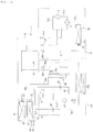
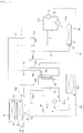
- FIG. 1A is a configuration diagram showing an air conditioner according to an embodiment of the present invention
- FIG. 1B is a control block diagram of the air conditioner according to the embodiment of the present invention.
- the air conditioner includes an air-conditioning cycle circuit 1 and a refrigeration cycle circuit 2.
- the air-conditioning cycle circuit 1 may include an air-conditioning outdoor unit O1 that is installed outdoors and an air-conditioning indoor unit I1 that is installed indoors.
- the refrigeration cycle circuit 2 may include a refrigeration outdoor unit 02 that is installed outdoors and a refrigeration indoor unit I2 that is installed indoors.
- the air-conditioning cycle circuit 1 may air-condition (or cool/heat) the interior of a room.
- the refrigeration cycle circuit 2 may refrigerate (or cool/freeze) food stored in the refrigeration indoor unit I2.
- the air-conditioning cycle circuit 1 may include a first compressor 11, an outdoor heat exchanger 13, a first expansion device 14 and 15, and an indoor heat exchanger 16. That is, the air-conditioning cycle circuit 1 includes a first compressor 11 for compressing a first refrigerant, a first condenser for condensing the first refrigerant compressed by the first compressor 11, a first expansion device 14 and 15 for expanding the first refrigerant that has passed through the first condenser, and a first evaporator for evaporating the refrigerant that has passed through the first expansion device 14 and 15. The first refrigerant that has passed through the first evaporator is supplied to the first compressor 11 again.
- a refrigerant may sequentially circulate through the first compressor 11, the outdoor heat exchanger 13, the first expansion device 14 and 15, the indoor heat exchanger 16, and the first compressor 11.
- the outdoor heat exchanger 13 may function as a first condenser
- the indoor heat exchanger 16 may function as a first evaporator.
- a refrigerant may sequentially circulate through the first compressor 11, the indoor heat exchanger 16, the first expansion device 14 and 15, the outdoor heat exchanger 13, and the first compressor 11.
- the outdoor heat exchanger 13 may function as a first evaporator
- the indoor heat exchanger 16 may function as a first condenser.
- the air-conditioning cycle circuit 1 may further include a cooling/heating switching valve 12 configured to enable a refrigerant to circulate through the first compressor 11, the outdoor heat exchanger 13, the first expansion device 14 and 15, and the indoor heat exchanger 16 when the cooling operation is performed and to enable a refrigerant to circulate through the first compressor 11, the indoor heat exchanger 16, the first expansion device 14 and 15, and the outdoor heat exchanger 13 when the heating operation is performed.
- a cooling/heating switching valve 12 configured to enable a refrigerant to circulate through the first compressor 11, the outdoor heat exchanger 13, the first expansion device 14 and 15, and the indoor heat exchanger 16 when the cooling operation is performed and to enable a refrigerant to circulate through the first compressor 11, the indoor heat exchanger 16, the first expansion device 14 and 15, and the outdoor heat exchanger 13 when the heating operation is performed.
- the first compressor 11 may suck a refrigerant, may compress the refrigerant, and may then discharge the compressed refrigerant.
- a plurality of the first compressors 11 may be connected in parallel or in series.
- a suction flow channel 11a through which a refrigerant is sucked into the first compressor 11 may be connected to the first compressor 11.
- a discharge flow channel 11b through which a compressed refrigerant is discharged from the first compressor 11 may be connected to the first compressor 11.
- the suction flow channel 11a may be connected to the plurality of first compressors 11 in parallel
- the discharge flow channel 11b may be connected to the plurality of first compressors 11 in parallel.
- the outdoor heat exchanger 13 may function as the first condenser in which a refrigerant compressed by the first compressor 11 is condensed when the cooling operation is performed.
- the outdoor heat exchanger 13 may function as the first evaporator in which a refrigerant expanded by the first expansion device 14 and 15 is evaporated when the heating operation is performed.
- the outdoor heat exchanger 13 may be embodied as an air-refrigerant heat exchanger configured to perform heat exchange between outdoor air and a refrigerant.
- the outdoor heat exchanger 13 may be embodied as a water-refrigerant heat exchanger configured to perform heat exchange between heat source water, such as water or antifreeze, and a refrigerant.
- the first expansion device 14 and 15 may include an outdoor expansion valve 14 for expanding a refrigerant flowing toward the outdoor heat exchanger 13.
- the first expansion device 14 and 15 may include an indoor expansion valve 15 for controlling a refrigerant flowing into or out of the indoor heat exchanger 16.
- the outdoor expansion valve 14 may be installed between the indoor expansion valve 15 and the outdoor heat exchanger 13, and may be installed closer to the outdoor heat exchanger 13 than to the indoor heat exchanger 16.
- the outdoor expansion valve 14 may not expand a refrigerant when the cooling operation is performed, but may expand a refrigerant when the heating operation is performed.
- the outdoor expansion valve 14 may be fully open in the cooling operation, and the opening degree thereof may be controlled to a set value in the heating operation.
- the outdoor expansion valve 14 may be installed on a bypass pipe installed on a refrigerant pipe between the outdoor heat exchanger 13 and the indoor expansion valve 15.
- a check valve configured to enable a refrigerant to flow toward the indoor expansion valve 15 in the cooling operation and to enable a refrigerant to flow toward the outdoor expansion valve 14 by blocking the refrigerant in the heating operation may be installed on the refrigerant pipe between the outdoor heat exchanger 13 and the indoor expansion valve 15.
- the indoor expansion valve 15 may be installed between the outdoor heat exchanger 13 and the indoor heat exchanger 16, and may be installed closer to the indoor heat exchanger 16 than to the outdoor heat exchanger 13.
- the indoor heat exchanger 16 may function as the first evaporator in which a refrigerant expanded by the first expansion device 14 and 15 is evaporated when the cooling operation is performed.
- the indoor heat exchanger 16 may function as the first condenser in which a refrigerant compressed by the first compressor 11 is condensed when the heating operation is performed.
- the cooling/heating switching valve 12 may be formed of a 4-way valve. That is, the cooling/heating switching valve 12 may be connected to the first compressor 11 through the suction flow channel 11a of the first compressor 11, may be connected to the first compressor 11 through the discharge flow channel 11b of the first compressor 11, may be connected to the outdoor.heat exchanger 13 through a suction/discharge flow channel 13a of the outdoor heat exchanger 13, and may be connected to the indoor heat exchanger 16 through an air-conditioning gas line 17.
- outdoor heat exchanger 13 and the indoor heat exchanger 16 may be connected to each other through an air-conditioning liquid line 18.
- An air-conditioning gas line valve 17a configured to open/shut the air-conditioning gas line 17 may be installed on the air-conditioning gas line 17.
- An air-conditioning liquid line valve 18a configured to open/shut the air-conditioning liquid line 18 may be installed on the air-conditioning liquid line 18.
- the air-conditioning cycle circuit 1 may further include a first accumulator (not shown) installed between the cooling/heating switching valve 12 and the first compressor 11.
- the first accumulator is installed on the suction flow channel 11a of the first compressor 11. Accordingly, a refrigerant that flows from the cooling/heating switching valve 12 toward the first compressor 11 may flow into the first accumulator.
- a liquid-state refrigerant, among the refrigerant that has flowed into the first accumulator may accumulate in the first accumulator, and a gaseous-state refrigerant, among the refrigerant that has flowed into the first accumulator, may be sucked into the first compressor 11.
- the refrigeration cycle circuit 2 may include a second compressor 21, a second condenser 23, a second expansion device 25, and a second evaporator 26.
- a second refrigerant may sequentially circulate through the second compressor 21, the second condenser 23, the second expansion device 25, the second evaporator 26, and the second compressor 21.
- the second compressor 21 may suck a refrigerant, may compress the refrigerant, and may discharge the compressed refrigerant.
- a plurality of the second compressors 21 may be connected in parallel or in series.
- a suction flow channel 21a through which a refrigerant is sucked into the second compressor 21 may be connected to the second compressor 21.
- a discharge flow channel 21c through which a compressed refrigerant is discharged from the second compressor 21 may be connected to the second compressor 21.
- the suction flow channel 21a may be connected to the plurality of second compressors 21 in parallel
- the discharge flow channel 21c may be connected to the plurality of second compressors 21 in parallel.
- the second condenser 23 condenses a refrigerant compressed by the second compressor 21.
- the second condenser 23 may be embodied as an air-refrigerant heat exchanger configured to perform heat exchange between outdoor air and a refrigerant.
- the second condenser 23 may be embodied as a water-refrigerant heat exchanger configured to perform heat exchange between heat source water, such as water or antifreeze, and a refrigerant.
- a condenser fan 23a for supplying outdoor air to the second condenser 23 may be disposed close to the second condenser 23.
- the second expansion device 25 expands a refrigerant that enters the second evaporator 26.
- the second expansion device 25 may be installed between the second condenser 23 and the second evaporator 26, and may be installed closer to the second evaporator 26 than to the second condenser 23.
- the second evaporator 26 may evaporate a refrigerant while refrigerating food stored in the refrigeration indoor unit I2 by performing heat exchange between the refrigerant expanded by the second expansion device 25 and the air within the refrigeration indoor unit I2.
- the second compressor 21 may be connected to the second evaporator 26 through the suction flow channel 21a. Further, the second compressor 21 may be connected to the second condenser 23 through the discharge flow channel 21c. Furthermore, the second condenser 23 and the second evaporator 26 may be connected to each other through a refrigeration liquid line 26a.
- a first suction flow channel valve 21b configured to open/shut the suction flow channel 21a is installed on the suction flow channel 21a of the second compressor 21.
- a second suction flow channel valve 26b configured to open/shut the refrigeration liquid line 26a is installed on the refrigeration liquid line 26a.
- the refrigeration cycle circuit 2 may further include a second accumulator 70 installed between the second evaporator 26 and the second compressor 21.
- the second accumulator 70 is installed on the suction flow channel 21a of the second compressor 21. Accordingly, a refrigerant flowing from the second evaporator 26 toward the second compressor 21 may flow into the second accumulator 70, a liquid-state refrigerant, among the refrigerant that has flowed into the second accumulator 70, may accumulate in the second accumulator 70, and a gaseous-state refrigerant, among the refrigerant that has flowed into the second accumulator 70, may be sucked into the second compressor 21.
- the air conditioner according to the embodiment of the present invention further includes a cooling receiver 50 configured to perform heat exchange between the refrigerant that has passed through the second condenser 23 and the refrigerant that has passed through one of the indoor heat exchanger 16 and the outdoor heat exchanger 13, which functions as the first condenser, and to store the heat-exchanged refrigerant.
- a cooling receiver 50 configured to perform heat exchange between the refrigerant that has passed through the second condenser 23 and the refrigerant that has passed through one of the indoor heat exchanger 16 and the outdoor heat exchanger 13, which functions as the first condenser, and to store the heat-exchanged refrigerant.
- the embodiment may further include an outdoor air temperature sensor 83 configured to measure the temperature of outdoor air.
- the outdoor air temperature sensor 83 measures the temperature of outdoor air and transmits the measured temperature to a control unit 90.
- the embodiment further includes an oil level sensor 22 configured to detect the amount of oil within the second compressor 21.
- the oil level sensor 22 detects the amount of oil within the second compressor 21 and transmits the information about the amount of oil to the control unit 90.
- a discharge temperature sensor 81 configured to measure the temperature of the second refrigerant discharged from the second evaporator 26 is mounted on the suction flow channel 21a of the second compressor 21.
- the discharge temperature sensor 81 transmits the information about the temperature of the refrigerant discharged from the second evaporator 26 to the control unit 90.
- the discharge temperature sensor 81 is disposed at a position of the suction flow channel 21a of the second compressor 21 that is close to the second evaporator 26. That is, the discharge temperature sensor 81 is disposed at a portion of the suction flow channel 21a of the second compressor 21 that is close to the second evaporator 26.
- a discharge pressure sensor 82 configured to detect the pressure of the second refrigerator discharged from the second evaporator 26 is installed on the suction flow channel 21a of the second compressor 21.
- the discharge pressure sensor 82 transmits the information about the pressure of the second refrigerant discharged from the second evaporator 26 to the control unit 90.
- a first bypass unit diverts a portion of the second refrigerant that has passed through the second compressor 21 so that the portion of the second refrigerant exchanges heat with the second refrigerant that has passed through the second evaporator 26.
- the first bypass unit When the cooling operation or the heating operation (normal operation) is performed, the first bypass unit is in a closed state.
- the first bypass unit supplies a portion of the high-temperature and high-pressure refrigerant discharged from the second compressor 21 to the suction flow channel 21a of the second compressor 21, which is the discharge port of the second evaporator 26.
- the first bypass unit enables a portion of the high-temperature and high-pressure refrigerant discharged from the second compressor 21 to bypass the second condenser 23, the second expansion device 25 and the second evaporator 26.
- the high-temperature and high-pressure refrigerant supplied to the suction flow channel 21a of the second compressor 21 by the first bypass unit increases the temperature of the second refrigerant within the suction flow channel 21a of the second compressor 21.
- the oil within the suction flow channel 21a of the second compressor 21 is increased in temperature and solubility and is decreased in viscosity.
- the oil, which has high viscosity and remains in the suction flow channel 21a of the second compressor 21 in normal operation, is decreased in viscosity and is therefore easily recovered to the second compressor 21 by the pressure of the refrigerant. Consequently, there is an effect in that the reliability of the second compressor 21 is improved.
- the first bypass unit includes a first bypass pipe 61, which connects the discharge flow channel 21c of the second compressor 21, which connects the second compressor 21 to the second condenser 23, to the suction flow channel 21a of the second compressor 21, which connects the second evaporator 26 to the second compressor 21, and a first control valve 63, which is installed on the first bypass pipe 61 in order to control the flow of the refrigerant.
- the first bypass pipe 61 guides a portion of the second refrigerant compressed by the second compressor 21 to the discharge port of the second evaporator 26.
- One end of the first bypass pipe 61 is connected to the discharge flow channel 21c of the second compressor 21 and the opposite end of the first bypass pipe 61 is connected to the suction flow channel 21a of the second compressor 21.
- the first control valve 63 controls the flow of the refrigerant passing through the first bypass pipe 61.
- the first control valve 63 may include a solenoid valve or an electronic expansion valve.
- the first control valve 63 includes an electronic expansion valve, which enables the opening degree thereof to be variably controlled.
- the opening degree of the first control valve 63 is controlled in response to the control signal from the control unit 90.
- the air conditioner according to the embodiment may perform the oil recovery operation during the cooling operation (normal operation) or may perform only the oil recovery operation while the cooling operation is stopped.
- "normal operation” refers to operation including the cooling operation, the heating operation and the refrigeration operation, other than the oil recovery operation.
- a second bypass unit diverts a portion of the second refrigerant that has passed through the second compressor 21 so that the portion of the second refrigerant exchanges heat with the second refrigerant that has passed through the second evaporator 26.
- the second bypass unit When the cooling operation or the heating operation is performed (i.e. upon normal operation), the second bypass unit is in a closed state.
- the second bypass unit additionally supplies a portion of the high-temperature and high-pressure refrigerant discharged from the second compressor 21 to the suction flow channel 21a of the second compressor 21, which is the discharge port of the second evaporator 26.
- the second bypass unit enables a portion of the high-temperature and high-pressure refrigerant discharged from the second compressor 21 to bypass the second condenser 23, the second expansion device 25 and the second evaporator 26.
- the high-temperature and high-pressure refrigerant supplied to the suction flow channel 21a of the second compressor 21 by the second bypass unit increases the temperature of the second refrigerant within the suction flow channel 21a of the second compressor 21.
- the oil within the suction flow channel 21a of the second compressor 21 is increased in temperature and solubility and is decreased in viscosity.
- the oil, which has high viscosity and remains in the suction flow channel 21a of the second compressor 21 in normal operation, is decreased in viscosity and is therefore easily recovered to the second compressor 21 by the pressure of the refrigerant. Consequently, there is an effect in that the reliability of the second compressor 21 is improved. That is, the second bypass unit functions to additionally increase the temperature of the second refrigerant within the suction flow channel 21a of the second compressor 21 in the environment in which the oil recovery operation is not smoothly performed by the first bypass unit.
- the second bypass unit includes a second bypass pipe 62, which connects the discharge flow channel 21c of the second compressor 21, which connects the second compressor 21 to the second condenser 23, to the suction flow channel 21a of the second compressor 21, which connects the second evaporator 26 to the second compressor 21, and a second control valve 64, which is installed on the second bypass pipe 62 in order to control the flow of the refrigerant.
- the second bypass pipe 62 guides a portion of the second refrigerant compressed by the second compressor 21 to the discharge port of the second evaporator 26.
- One end of the second bypass pipe 62 is connected to the discharge flow channel 21c of the second compressor 21 and the opposite end of the second bypass pipe 62 is connected to the suction flow channel 21a of the second compressor 21.
- the second control valve 64 controls the flow of the refrigerant passing through the second bypass pipe 62.
- the second control valve 64 may include a solenoid valve or an electronic expansion valve.
- the second control valve 64 includes an electronic expansion valve, which enables the opening degree thereof to be variably controlled. The opening degree of the second control valve 64 is controlled in response to the control signal from the control unit 90.
- connection positions of the first and second bypass pipes 61 and 62 are important.
- the connection position between the first bypass pipe 61 and the discharge flow channel of the second compressor 21 may be closer to the second compressor 21 than the connection position between the second bypass pipe 62 and the discharge flow channel of the second compressor 21, and the connection position between the first bypass pipe 61 and the suction flow channel of the second compressor 21 may be closer to the second compressor 21 than the connection position between the second bypass pipe 62 and the suction flow channel of the second compressor 21.
- the refrigerant When the temperature of the outdoor air is low, the refrigerant is guided to a position close to the second evaporator 26 through the second bypass pipe 62. Accordingly, the efficiency of the oil recovery operation may be enhanced and the operational load of the second accumulator may be reduced.
- the embodiment may further include a check valve, which is installed on the discharge flow channel of the second compressor 21 in order to prevent the second refrigerant that has passed through the second compressor 21 from flowing backward.
- the check valve may be disposed between the branch point of the first bypass pipe 61 and the branch point of the second bypass pipe 62.
- the refrigerant that flows into the suction flow channel 21a of the second compressor 21 through the first and second bypass pipes 61 and 62 may convert the refrigerant within the suction flow channel 21a of the second compressor 21 into a two-phase refrigerant. Therefore, the opposite end of the first bypass pipe 61 and the opposite end of the second bypass pipe 62, which are connected to the suction flow channel 21a of the second compressor 21, may be disposed between the second accumulator and the second evaporator 26. However, the opposite end of the first bypass pipe 61 and the opposite end of the second bypass pipe 62 may alternatively be disposed between the second accumulator and the second compressor 21.
- the control unit 90 controls the overall operation of the air conditioner.
- the control unit 90 may include a processing device, which performs a logical determination, and a memory.
- control unit 90 Based on various detected information, the control unit 90 performs control such that the air conditioner selectively performs normal operation or an oil recovery operation. During the oil recovery operation, the control unit 90 may perform control such that normal operation is performed or is stopped.
- the control unit 90 determines that the oil recovery operation is needed and starts the oil recovery operation. In an example, when the oil level value transmitted from the oil level sensor 22 is lower than a reference oil level value, the control unit 90 performs the oil recovery operation. When the oil level value transmitted from the oil level sensor 22 is higher than the reference oil level value, the control unit 90 performs normal operation. In another example, when a predetermined time has elapsed since the start of operation of the air conditioner, the control unit 90 may perform the oil recovery operation. Here, the predetermined time may be set within the range from 2 hours to 5 hours. Specifically, the control process in which the oil recovery operation is performed on the basis of time is used when communication with the second evaporator 26 installed in the showcase is impossible.
- the control unit 90 may determine that the oil recovery operation is needed and may start the oil recovery operation.
- the control unit 90 performs the oil recovery operation.
- the control unit 90 performs normal operation.
- control unit 90 controls the first bypass unit such that the second refrigerant that has been discharged from the second compressor 21 and the second refrigerant that has passed through the second evaporator 26 perform heat exchange with each other. That is, the control unit 90 controls the first bypass unit so as to guide the second refrigerant discharged from the second compressor 21 to the discharge port of the second evaporator 26.
- control unit 90 drives the second compressor 21 so as to supply cool air to the showcase.
- control unit 90 drives the second compressor 21 and opens the first control valve 63 so as to supply the high-temperature and high-pressure refrigerant to the suction flow channel 21a of the second compressor 21.
- control unit 90 may control the opening degree and the opening time of the first control valve 63.
- the control unit 90 in the oil recovery operation, the control unit 90 fully opens the first control valve 63.
- the control unit 90 controls the second control valve 64 so as to be open.
- the control unit 90 controls the second control valve 64 so as to be closed.
- control unit 90 may increase the operation speed of the second compressor 21 above the operation speed at the time of normal operation. In this case, the flow rate of the second refrigerant is increased and thus the recovery of the oil is smoothly achieved.
- control unit 90 may rotate the condenser fan 23a at a maximum speed.
- control unit 90 may stop the condenser fan 23a or may rotate the condenser fan 23a at a lower speed than in the refrigeration operation.
- the refrigeration load of the refrigeration cycle circuit may be reduced by varying the speed of the condenser fan 23a.
- the control unit 90 may perform control such that the above-described specific embodiments associated with the oil recovery operation are performed at the same time or at different times or such that only one of the embodiments is performed.
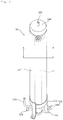
- FIG. 2 is a detailed view of the cooling receiver shown in FIG. 1
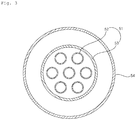
- FIG. 3 is a sectional view taken along line A-A in FIG. 2 .
- the cooling receiver 50 includes a cooling unit 51 and a receiver unit 54 in which at least one end of the cooling unit 51 is disposed.
- the cooling unit 51 includes at least one first refrigerant flow channel 52 through which a refrigerant that has passed through the second condenser 23 flows and a second refrigerant flow channel 53 configured to surround the outer circumference of some of the at least one first refrigerant flow channel 52.
- the refrigerant that has passed through one of the outdoor heat exchanger 13 and the indoor heat exchanger 16, which functions as the first condenser exchanges heat with the refrigerant flowing through the first refrigerant flow channel 52 while flowing through the inside of the second refrigerant flow channel 53. Accordingly, the refrigerant flowing through the first refrigerant flow channel 52 is supercooled, and the refrigerant flowing through the second refrigerant flow channel 53 is gasified.
- At least one end of the cooling unit 51 is disposed in the receiver unit 54, and a supercooled refrigerant flowing out of the first refrigerant flow channel 52 is stored in the receiver unit 54.
- the cooling unit 51 and the receiver unit 54 are formed to have a cylindrical shape having an empty space inside and are formed to be long in upward and downward directions.
- the diameter of the first refrigerant flow channel 52 may be the smallest, the diameter of the second refrigerant flow channel 53 may be greater than that of the first refrigerant flow channel 52, and the diameter of the receiver unit 54 may be greater than that of the second refrigerant flow channel 53.
- the first refrigerant flow channel 52 may be formed of seven small-diameter pipes.
- the cooling unit 51 may have an upper end inserted and disposed in the receiver unit 54 and may have a lower end protruding below the receiver unit 54 so as to be exposed outside the receiver unit 54.
- the upper end of the first refrigerant flow channel 52 which is disposed within the receiver unit 54, is open, and the upper end of the second refrigerant flow channel 53 is closed.
- the open upper end of the first refrigerant flow channel 52 may protrude upwards from the upper end of the second refrigerant flow channel 53. Accordingly, refrigerant flowing through the first refrigerant flow channel 52 may be supercooled through heat exchange with a refrigerant flowing through the second refrigerant flow channel 53. Subsequently, the supercooled refrigerant may flow out of the open upper end of the first refrigerant flow channel 52 and may be stored in the internal space of the receiver unit 54.
- a first inlet flow channel 52a and a second inlet flow channel 53a are disposed in a portion of the cooling unit 51 that protrudes below the receiver unit 54. Further, a first outlet flow channel 53b is disposed above the receiver unit 54, and a second outlet flow channel 54a is disposed below the receiver unit 54.
- the first inlet flow channel 52a is connected to the first refrigerant flow channel 52 through the second refrigerant flow channel 53.
- the first inlet flow channel 52a supplies the first refrigerant flow channel 52 with refrigerant that has passed through the second condenser 23.
- the first inlet flow channel 52a may branch into a plurality of first inlet flow channels within the second refrigerant flow channel 53 and the plurality of first inlet flow channels may be connected to the plurality of first refrigerant flow channels 52.
- the second inlet flow channel 53a is connected to the second refrigerant flow channel 53.
- the second inlet flow channel 53a supplies the second refrigerant flow channel 53 with refrigerant that has passed through one of the outdoor heat exchanger 13 and the indoor heat exchanger 16, which functions as the first condenser.
- the second refrigerant flow channel 53 is connected to the air-conditioning liquid line 18 via a heat-recovery liquid line 34 branching from the air-conditioning liquid line 18 that connects the second outdoor heat exchanger 13 and the indoor heat exchanger 16. That is, the heat-recovery liquid line 34 connects the second refrigerant flow channel 53 and the air-conditioning liquid line 18.
- a heat recovery expansion device 34a is installed on the heat-recovery liquid line 34.
- a portion of the refrigerant that has passed through the first condenser may move to the first evaporator through the air-conditioning liquid line 18.
- the remainder of the refrigerant may move to the heat-recovery liquid line 34, may be expanded by the heat recovery expansion device 34a, and may then move to the second inlet flow channel 53a.
- the refrigerant that has moved to the second inlet flow channel 53a may be supplied to the second refrigerant flow channel 53.
- the first outlet flow channel 53b is connected to the upper portion of the second refrigerant flow channel 53 within the receiver unit 54 through the upper end of the receiver unit 54. Accordingly, refrigerant supplied to the second refrigerant flow channel 53 through the second inlet flow channel 53a may pass through the second refrigerant flow channel 53 and may then escape through the first outlet flow channel 53b.
- the first outlet flow channel 53b protruding above the receiver unit 54 is connected to the suction flow channel 11a of the first compressor 11 via a heat-recovery gas line 35. Accordingly, the refrigerant that has escaped through the first outlet flow channel 53b may move to the suction flow channel 11a of the first compressor 11 through the heat-recovery gas line 35 and may then be supplied to the first compressor 11.
- the second outlet flow channel 54a is connected to the refrigeration liquid line 26a. Accordingly, supercooled refrigerant that has escaped through the upper end of the first refrigerant flow channel 52 and is stored in the receiver unit 54 may escape through the second outlet flow channel 54a, may move to the refrigeration liquid line 26a, and may then be supplied to the second evaporator 26.
- a cap 54b configured to cover the upper end of the receiver unit 54 may be disposed in the upper end of the receiver unit 54.
- the first outlet flow channel 53b may penetrate the cap 54b.
- the mounting bracket 55 may be disposed in the lower portion of the receiver unit 54.
- the mounting bracket 55 may include a ring-shaped main body unit 55a configured to surround the outer circumferential surface of the receiver unit 54 and a plurality of mounting units 55b disposed on the outer circumferential surface of the main body unit 55a while being equidistantly spaced apart from each other.
- the mounting bracket 55 may include three mounting units 55b.
- the mounting unit 55b may be mounted on the refrigeration outdoor unit 02 so as to couple the receiver unit 54 to the refrigeration outdoor unit 02.
- a heat-recovery liquid line valve 34b configured to open/shut the heat-recovery liquid line 34 is installed on the heat-recovery liquid line 34.
- Heat-recovery gas line valves 35a and 35b configured to open/shut the heat-recovery gas line 35 are installed on the heat-recovery gas line 35.
- the heat-recovery gas line valves 35a and 35b include a first heat-recovery gas line valve 35a disposed in the refrigeration outdoor unit 02 and a second heat-recovery gas line valve 35b disposed in the air-conditioning outdoor unit O1.
- the air-conditioning gas line valve 17a, the air-conditioning liquid line valve 18a, the first suction flow channel valve 21b, the second suction flow channel valve 26b, the heat-recovery liquid line valve 34b, and the heat-recovery gas line valves 35a and 35b may be open at normal times and may be shut by a worker when maintenance or repair of the air conditioner (for example, filling with a refrigerant or correcting a malfunction) is performed.
- the first compressor 11, the four-way valve 12, the outdoor heat exchanger 13, the outdoor expansion valve 14, the air-conditioning gas line valve 17a, the air-conditioning liquid line valve 18a, and the second heat-recovery gas line valve 35b may be included in the air-conditioning outdoor unit O1.
- the second compressor 21, the second condenser 23, the cooling receiver 50, the first suction flow channel valve 21b, the second suction flow channel valve 26b, the heat-recovery liquid line valve 34b, and the first heat-recovery gas line valve 35a may be included in the refrigeration outdoor unit 02.
- the indoor heat exchanger 16 and the indoor expansion valve 15 may be included in the air-conditioning indoor unit I1.
- the second evaporator 26 and the second expansion device 25 may be included in the refrigeration indoor unit 12.
- FIG. 4 is a diagram showing the flow of refrigerant when the cooling operation and the refrigeration operation of the air conditioner according to the embodiment of the present invention are performed at the same time.
- the air conditioner according to the embodiment of the present invention may perform a cooling operation for cooling the interior of a room and a refrigeration operation for refrigerating food within the refrigeration indoor unit I2 at the same time.
- the first compressor 11 when the cooling operation of the air-conditioning cycle circuit 1 is performed, the first compressor 11 is driven to discharge a refrigerant.
- the refrigerant discharged by the first compressor 11 moves to the cooling/heating switching valve 12 through the discharge flow channel 11b of the first compressor 11.
- the refrigerant that has moved to the cooling/heating switching valve 12 moves to the outdoor heat exchanger 13 through the suction/discharge flow channel 13a of the outdoor heat exchanger 13.
- the outdoor heat exchanger 13 When the cooling operation of the air-conditioning cycle circuit 1 is performed, the outdoor heat exchanger 13 functions as the first condenser.
- a portion of the refrigerant that has passed through the outdoor heat exchanger 13 moves to the indoor heat exchanger 16 through the air-conditioning liquid line 18.
- the remainder of the refrigerant that has passed through the outdoor heat exchanger 13 moves to the cooling receiver 50 through the heat-recovery liquid line 34.
- a portion of the refrigerant that belongs to the refrigerant that has passed through the outdoor heat exchanger 13 and that moves to the indoor heat exchanger 16 through the air-conditioning liquid line 18 is supplied to the indoor heat exchanger 16 in the state in which the refrigerant has been expanded by the first expansion device 15.
- the indoor heat exchanger 16 functions as the first evaporator.
- the refrigerant that has moved to the indoor heat exchanger 16 may refrigerate indoor air and may be evaporated through heat exchange with the indoor air.
- the refrigerant evaporated by the indoor heat exchanger 16 may move to the cooling/heating switching valve 12 through the air-conditioning gas line 17 and may then be supplied to the first compressor 11 again through the suction flow channel 11a of the first compressor 11.
- the second compressor 21 is driven to discharge a refrigerant.
- the refrigerant discharged by the second compressor 21 moves to the second condenser 23 through the discharge flow channel 21c of the second compressor 21.
- the refrigerant that has moved to the second condenser 23 moves to the second evaporator 26 through the refrigeration liquid line 26a.
- the refrigerant that has passed through the second condenser 23 is supplied to the second evaporator 26 in the state in which the refrigerant has been expanded by the second expansion device 25.
- the refrigerant that has moved to the second evaporator 26 may refrigerate food within the refrigeration indoor unit 12 and may be evaporated through heat exchange with air within the refrigeration indoor unit 12.
- the refrigerant evaporated by the second evaporator 26 may be supplied to the second compressor 21 again through the suction flow channel 21a of the second compressor 21.
- the remaining refrigerant that belongs to the refrigerant that has passed through the outdoor heat exchanger 13 of the air-conditioning cycle circuit 1 and that moves to the cooling receiver 50 through the heat-recovery liquid line 34 may be expanded by the heat recovery expansion device 34a, may move to the second refrigerant flow channel 53, and may be gasified through heat exchange with the refrigerant that has passed through the second condenser 23 of the refrigeration cycle circuit 2 within the cooling receiver 50 while supercooling the refrigerant that has passed through the second condenser 23.
- the cooling receiver 50 may be installed between the second condenser 23 and the second expansion device 25 on the refrigeration liquid line 26a.
- the refrigerant that has passed through the second condenser 23 may exchange heat with the refrigerant flowing through the second refrigerant flow channel 53 and may be supercooled while flowing through the first refrigerant flow channel 52.
- the refrigerant supercooled while flowing through the first refrigerant flow channel 52 may escape through the open upper end of the first refrigerant flow channel 52 and may then be stored in the receiver unit 54.
- the refrigerant gasified while flowing through the second refrigerant flow channel 53 may escape from the first outlet flow channel 53b, may move to the suction flow channel 11a of the first compressor 11 through the heat-recovery gas line 35, and may then be supplied to the first compressor 11. Furthermore, the supercooled refrigerant stored in the receiver unit 54 may escape through the second outlet flow channel 54a, may move to the refrigeration liquid line 26a, and may then be supplied to the second evaporator 26 in the state in which the refrigerant has been expanded by the second expansion device 25. At least one of the opening time and the opening degree of the second expansion device 25 is controlled by the control unit so that the amount of refrigerant within the refrigeration cycle circuit 2 is optimized.
- the control unit 90 opens the heat recovery expansion device 34a at a minimum opening degree when the cooling operation is performed. Accordingly, it is possible to prevent deterioration of the efficiency of the air-conditioning cycle circuit due to excessive heat absorption in the refrigeration cycle circuit when the cooling operation is performed.
- FIG. 5 is a diagram showing the flow of refrigerant when the heating operation and the refrigeration operation of the air conditioner according to the embodiment of the present invention are performed at the same time.
- the air conditioner according to the embodiment of the present invention may perform a heating operation for heating the interior of a room and a refrigeration operation for refrigerating food within the refrigeration indoor unit 12 at the same time.
- the first compressor 11 when the heating operation of the air-conditioning cycle circuit 1 is performed, the first compressor 11 is driven to discharge a refrigerant.
- the refrigerant discharged by the first compressor 11 moves to the cooling/heating switching valve 12 through the discharge flow channel 11b of the first compressor 11.
- the refrigerant that has moved to the cooling/heating switching valve 12 moves to the indoor heat exchanger 16 through the air-conditioning gas line 17.
- the indoor heat exchanger 16 functions as the first condenser.
- a portion of the refrigerant that has passed through the indoor heat exchanger 16 moves to the outdoor heat exchanger 13 through the air-conditioning liquid line 18.
- the remainder of the refrigerant that has passed through the indoor heat exchanger 16 moves to the cooling receiver 50 through the heat-recovery liquid line 34.
- a portion of the refrigerant that belongs to the refrigerant that has passed through the indoor heat exchanger 16 and that moves to the outdoor heat exchanger 13 through the air-conditioning liquid line 18 is supplied to the outdoor heat exchanger 13 in the state in which the refrigerant has been expanded by the first expansion device 14.
- the outdoor heat exchanger 13 functions as the first evaporator.
- the refrigerant that has moved to the outdoor heat exchanger 13 may be evaporated while exchanging heat with outdoor air.
- the refrigerant evaporated by the outdoor heat exchanger 13 may move to the cooling/heating switching valve 12 through the suction/discharge flow channel 13a of the outdoor heat exchanger 13 and may then be supplied to the first compressor 11 again through the suction flow channel 11a of the first compressor 11.
- the second compressor 21 is driven to discharge a refrigerant.
- the refrigerant discharged by the second compressor 21 moves to the second condenser 23 through the discharge flow channel 21c of the second compressor 21.
- the refrigerant that has moved to the second condenser 23 moves to the second evaporator 26 through the refrigeration liquid line 26a.
- the refrigerant that has passed through the second condenser 23 is supplied to the second evaporator 26 in the state in which the refrigerant has been expanded by the second expansion device 25.
- the refrigerant that has moved to the second evaporator 26 may refrigerate food within the refrigeration indoor unit I2 and may be evaporated through heat exchange with air within the refrigeration indoor unit 12.
- the refrigerant evaporated by the second evaporator 26 may be supplied to the second compressor 21 again through the suction flow channel 21a of the second compressor 21.
- the remaining refrigerant that belongs to the refrigerant that has passed through the indoor heat exchanger 16 of the air-conditioning cycle circuit 1 and that moves to the cooling receiver 50 through the heat-recovery liquid line 34 may be expanded by the heat recovery expansion device 34a, may move to the second refrigerant flow channel 53, and may be gasified through heat exchange with the refrigerant that has passed through the second condenser 23 of the refrigeration cycle circuit 2 within the cooling receiver 50 while supercooling the refrigerant that has passed through the second condenser 23.
- the refrigerant that has passed through the second condenser 23 may be supercooled through heat exchange with the refrigerant flowing through the second refrigerant flow channel 53 while flowing through the first refrigerant flow channel 52.
- the refrigerant supercooled while flowing through the first refrigerant flow channel 52 may escape through the open upper end of the first refrigerant flow channel 52 and may be stored in the receiver unit 54.
- the refrigerant gasified while flowing through the second refrigerant flow channel 53 may escape from the first outlet flow channel 53b, may move to the suction flow channel 11a of the first compressor 11 through the heat-recovery gas line 35, and may then be supplied to the first compressor 11.
- the supercooled refrigerant stored in the receiver unit 54 may escape through the second outlet flow channel 54a, may move to the refrigeration liquid line 26a, and may then be supplied to the second evaporator 26 in the state in which the refrigerant has been expanded by the second expansion device 25.
- At least one of the opening time and the opening degree of the second expansion device 25 is controlled by the control unit so that the amount of refrigerant within the refrigeration cycle circuit 2 is optimized.
- the control unit 90 opens the heat recovery expansion device 34a to the maximum opening degree when the heating operation is performed. Accordingly, it is possible to use as much waste heat from the refrigeration cycle circuit for the air-conditioning cycle circuit as possible in the cooling operation, thereby improving the efficiency of the air-conditioning cycle circuit.
- FIG. 6 is a diagram showing the flow of refrigerant when only the refrigeration operation of the air conditioner according to the embodiment of the present invention is performed.
- the air conditioner according to the embodiment of the present invention may perform only a refrigeration operation for refrigerating food within the refrigeration indoor unit 12. That is, the air-conditioning cycle circuit 1 may not operate, and only the refrigeration cycle circuit 2 may operate.
- the second compressor 21 is driven to discharge a refrigerant.
- the refrigerant discharged by the second compressor 21 moves to the second condenser 23 through the discharge flow channel 21c of the second compressor 21.
- the refrigerant that has moved to the second condenser 23 moves to the second evaporator 26 through the refrigeration liquid line 26a.
- the refrigerant that has passed through the second condenser 23 is supplied to the second evaporator 26 in the state in which the refrigerant has been expanded by the second expansion device 25.
- the refrigerant that has moved to the second evaporator 26 may refrigerate food within the refrigeration indoor unit 12 and may be evaporated through heat exchange with air within the refrigeration indoor unit 12.
- the refrigerant evaporated by the second evaporator 26 may be supplied to the second compressor 21 again through the suction flow channel 21a of the second compressor 21.
- the refrigerant that has passed through the second condenser 23 may not be subjected to heat exchange while flowing through the first refrigerant flow channel 52, but may escape through the open upper end of the first refrigerant flow channel 52 and may then be stored in the receiver unit 54.
- the stored refrigerant may escape through the second outlet flow channel 54a, may move to the refrigeration liquid line 26a, and may then be supplied to the second evaporator 26 in the state in which the refrigerant has been expanded by the second expansion device 25.
- At least one of the opening time and the opening degree of the second expansion device 25 may be controlled by the control unit so that the amount of refrigerant within the refrigeration cycle circuit 2 is optimized.
- FIG. 7 is a diagram showing the flow of refrigerant when the cooling operation, the refrigeration operation and the oil recovery operation of the air conditioner according to the embodiment of the present invention are performed at the same time.
- the second refrigerant compressed by the second compressor 21 is supplied to the suction flow channel 21a of the second compressor 21 by the first bypass unit.
- the high-temperature and high-pressure refrigerant increases the temperature of the second refrigerant within the suction flow channel 21a of the second compressor 21.
- the oil within the suction flow channel 21a of the second compressor 21 is increased in temperature and solubility and is decreased in viscosity.
- control unit 90 When the oil recovery operation is performed and the temperature of the outdoor air is lower than a predetermined temperature, the control unit 90 additionally opens the second control valve 64. Accordingly, the refrigerant compressed by the second compressor 21 is additionally supplied to the suction flow channel 21a of the second compressor 21 through the second bypass pipe 62.
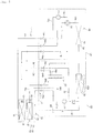
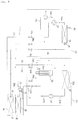
- FIG. 8A is a configuration diagram showing an air conditioner according to another embodiment of the present invention
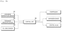
- FIG. 8B is a control block diagram of the air conditioner according to another embodiment of the present invention.
- the air conditioner according to another embodiment further includes a third bypass unit, in contrast with the above-described embodiment shown in FIG. 1 .
- the third bypass unit in this embodiment functions to guide a portion of the refrigerant that has been discharged from the second condenser 23 to the discharge port of the second evaporator 26.
- the third bypass unit When the cooling operation (normal operation) is performed, the third bypass unit is in a closed state.
- the third bypass unit supplies a portion of the high-temperature and high-pressure refrigerant that has been discharged from the second condenser 23 to the suction flow channel 21a of the second compressor 21, which is the discharge port of the second evaporator 26.
- the high-temperature and high-pressure refrigerant supplied to the suction flow channel 21a of the second compressor 21 by the third bypass unit converts the refrigerant within the suction flow channel 21a of the second compressor 21 into a two-phase refrigerant and increases the temperature.
- the oil within the suction flow channel 21a of the second compressor 21 is increased in temperature and solubility and is decreased in viscosity.
- the oil which has high viscosity and remains in the suction flow channel 21a of the second compressor 21 in normal operation, is decreased in viscosity and is therefore easily recovered to the compressor 21 by the pressure of the refrigerant. Consequently, there is an effect in that the reliability of the compressor 21 is improved.
- the third bypass unit includes a third bypass pipe 71, which connects the refrigeration liquid line 26a, which connects the second condenser 23 to the second evaporator 26, to the suction flow channel 21a of the second compressor 21, which connects the second evaporator 26 to the second compressor 21, and a control valve 72, which is installed on the third bypass pipe 71 in order to control the flow of the refrigerant.
- the third bypass pipe 71 guides a portion of the refrigerant condensed by the second condenser 23 to the discharge port of the second evaporator 26.
- One end of the third bypass pipe 71 is connected to the refrigeration liquid line 26a and the opposite end of the third bypass pipe 71 is connected to the suction flow channel 21a of the second compressor 21.
- connection position of the third bypass pipe 71 is important. In terms of the length and efficiency of the pipe, the connection position between the third bypass pipe 71 and the suction flow channel 21a of the second compressor 21 may be closer to the second evaporator 26 than to the second compressor 21.
- the third bypass pipe 71 is connected to a portion of the suction flow channel 21a of the second compressor 21 that is located close to the second evaporator 26.
- connection positon between the opposite end of the third bypass pipe 71 and the suction flow channel 21a of the second compressor 21 is closer to the second evaporator 26 than the connection position between the opposite end of the first or second bypass pipe 61 or 62 and the suction flow channel 21a of the second compressor 21.
- the control valve 72 controls the flow of the refrigerant passing through the third bypass pipe 71.
- the control valve 72 may include a solenoid valve or an electronic expansion valve.
- the control valve 72 includes an electronic expansion valve, which enables the opening degree thereof to be variably controlled.
- the opening degree of the control valve 72 is controlled in response to the control signal from the control unit 90.
- the air conditioner according to the embodiment may perform the oil recovery operation during the cooling operation (normal operation) or may perform only the oil recovery operation while the cooling operation is stopped.
- FIG. 9 is a diagram showing the flow of refrigerant when the cooling operation, the refrigeration operation and the oil recovery operation of the air conditioner according to another embodiment of the present invention are performed at the same time.
- the operation of the air conditioner shown in FIG. 9 has a difference from the operation of the air conditioner shown in FIG. 7 as to the operation of the third bypass unit.
- the operation of the air conditioner according to another embodiment shown in FIG. 9 and the operation shown in FIG. 7 will be described.
- the control unit 90 when the oil recovery operation is performed, the control unit 90 performs control such that the third bypass unit enables heat exchange between the second refrigerant that has been discharged from the second condenser 23 and the second refrigerant that has passed through the second evaporator 26. That is, the control unit 90 performs control such that the third bypass unit guides the second refrigerant discharged from the second condenser 23 to the discharge port of the second evaporator 26.
- control unit 90 drives the second compressor 21 so as to supply cool air to the showcase.
- control unit 90 drives the second compressor 21 and opens the control valve 72 so as to supply the second refrigerant discharged from the second condenser 23 to the suction flow channel 21a of the second compressor 21.
- the control unit 90 may control the opening degree and the opening time of the control valve 72.
- the high-pressure refrigerant supplied by the third bypass unit increases the temperature of the second refrigerant within the suction flow channel 21a of the second compressor 21.
- the oil within the suction flow channel 21a of the second compressor 21 is increased in temperature and solubility and is decreased in viscosity.
- a supercooler and a receiver are integrated, which leads to a compact design, a simple structure, a low price and improved refrigeration efficiency.
- the air conditioner according to the embodiment of the present invention has an effect in that two or more components are combined into a single unit, thus leading to a compact design and a simple structure.
- the air conditioner according to the embodiment of the present invention has effects of a low price and improved refrigeration efficiency.
- the air conditioner according to the embodiment of the present invention has an effect of overcoming a problem in which recovery of oil is not smoothly performed due to the considerably low temperature of an evaporator of a showcase.
Landscapes
- Engineering & Computer Science (AREA)
- Mechanical Engineering (AREA)
- General Engineering & Computer Science (AREA)
- Physics & Mathematics (AREA)
- Thermal Sciences (AREA)
- Chemical & Material Sciences (AREA)
- Combustion & Propulsion (AREA)
- Signal Processing (AREA)
- Fuzzy Systems (AREA)
- Mathematical Physics (AREA)
- Fluid Mechanics (AREA)
- Air Conditioning Control Device (AREA)
Claims (14)
- Climatiseur, comprenant :un circuit de cycle de climatisation (1) comprenant un premier compresseur (11) destiné à comprimer un premier réfrigérant, un premier condensateur (13) destiné à condenser le premier réfrigérant comprimé par le premier compresseur (11), un premier dispositif de détente (14, 15) destiné à détendre le premier réfrigérant ayant traversé le premier condensateur (13), et un premier évaporateur (16) destiné à évaporer le premier réfrigérant ayant traversé le premier dispositif de détente (14, 15), le circuit de cycle de climatisation (1) exécutant une opération de climatisation par circulation du premier réfrigérant ;un circuit de cycle de réfrigération (2) comprenant un deuxième compresseur (21) destiné à comprimer un deuxième réfrigérant, un deuxième condensateur (23) destiné à condenser le deuxième réfrigérant comprimé par le deuxième compresseur (21), un deuxième dispositif de détente (25) destiné à détendre le deuxième réfrigérant ayant traversé le deuxième condensateur (23), et un deuxième évaporateur (26) destiné à évaporer le deuxième réfrigérant ayant traversé le deuxième dispositif de détente (25), le circuit de cycle de réfrigération (2) refroidissant les aliments stockés par circulation du deuxième réfrigérant ; caractérisé en ce que ledit climatiseur comprend en outre un récepteur de refroidissement (50) destiné à effectuer un échange de chaleur entre le premier réfrigérant ayant traversé le premier condensateur (13) et le deuxième réfrigérant ayant traversé le deuxième condensateur (23) ;une première unité de dérivation destinée à dériver une fraction du deuxième réfrigérant ayant traversé le deuxième compresseur (21) de manière à échanger de la chaleur avec le deuxième réfrigérant ayant traversé le deuxième évaporateur (26) ; etune unité de commande (90) destinée à commander le fonctionnement général du climatiseur,où, si une opération de récupération d'huile est effectuée, l'unité de commande (90) est prévue pour exécuter une commande telle que la première unité de dérivation permet un échange de chaleur entre le deuxième réfrigérant refoulé du deuxième compresseur (21) et le deuxième réfrigérant ayant traversé le deuxième évaporateur (26), etoù la première unité de dérivation comprend :un premier conduit de dérivation (61) reliant un canal de refoulement (21c) du deuxième compresseur (21), ledit canal de refoulement reliant le deuxième compresseur (21) au deuxième condensateur (23), à un canal d'aspiration (21a) du deuxième compresseur (21), ledit canal d'aspiration reliant le deuxième évaporateur (26) au deuxième compresseur (21) ; etune première vanne de régulation (63) montée dans le premier conduit de dérivation (61) pour commander le débit de réfrigérant.
- Climatiseur selon la revendication 1, comprenant en outre :
une deuxième unité de dérivation destinée à dériver une fraction du deuxième réfrigérant ayant traversé le deuxième compresseur (21) pour échanger de la chaleur avec le deuxième réfrigérant ayant traversé le deuxième évaporateur (26). - Climatiseur selon la revendication 2, où la deuxième unité de dérivation comprend :un deuxième conduit de dérivation (62) reliant le canal de refoulement (21c) du deuxième compresseur (21) au canal d'aspiration (21a) du deuxième compresseur (21) ; etune deuxième vanne de régulation (64) montée dans le deuxième conduit de dérivation (62) pour commander le débit de réfrigérant,où le premier conduit de dérivation (61) et le deuxième conduit de dérivation (62) sont disposés de sorte qu'un emplacement de connexion entre le premier conduit de dérivation (61) et le canal de refoulement (21c) du deuxième compresseur (21) est plus proche du deuxième compresseur (21) qu'un emplacement de connexion entre le deuxième conduit de dérivation (62) et le canal de refoulement (21c) du deuxième compresseur (21) et de sorte qu'un emplacement de connexion entre le premier conduit de dérivation (61) et le canal d'aspiration (21a) du deuxième compresseur (21) est plus proche du deuxième compresseur (21) qu'un emplacement de connexion entre le deuxième conduit de dérivation (62) et le canal d'aspiration (21a) du deuxième compresseur (21).
- Climatiseur selon la revendication 3, comprenant en outre :une vanne antiretour montée dans le canal de refoulement (21c) du deuxième compresseur (21) afin d'empêcher un flux de retour du deuxième réfrigérant ayant traversé le deuxième compresseur (21),la vanne antiretour étant disposée entre un emplacement de branchement du premier conduit de dérivation (61) et un emplacement de branchement du deuxième conduit de dérivation (62).
- Climatiseur selon l'une des revendications 1 à 4, où, après écoulement d'un temps défini depuis le début du fonctionnement du climatiseur, l'unité de commande (90) est prévue pour exécuter l'opération de récupération d'huile.
- Climatiseur selon l'une des revendications 1 à 5, comprenant en outre :un capteur de niveau d'huile (22) destiné à détecter une quantité d'huile à l'intérieur du deuxième compresseur (21),où, si une valeur de niveau d'huile transmise par le capteur de niveau d'huile (22) est inférieure à une valeur de niveau d'huile de référence, l'unité de commande (90) exécute l'opération de récupération d'huile.
- Climatiseur selon la revendication 3, où, si l'opération de récupération d'huile est effectuée, l'unité de commande (90) est prévue pour exécuter une commande d'ouverture de la première vanne de régulation (63).
- Climatiseur selon la revendication 7, comprenant en outre :un capteur de température d'air extérieur (83) destiné à mesurer la température de l'air extérieur,où, si l'opération de récupération d'huile est effectuée et que la température de l'air extérieur est inférieure à une température définie, l'unité de commande (90) est prévue pour exécuter une commande d'ouverture de la deuxième vanne de régulation (64), etsi l'opération de récupération d'huile est effectuée et que la température de l'air extérieur est supérieure à une température définie, l'unité de commande (90) est prévue pour exécuter une commande de fermeture de la deuxième vanne de régulation (64).
- Climatiseur selon l'une des revendications 1 à 8, où, si l'opération de récupération d'huile est effectuée, l'unité de commande augmente la vitesse de fonctionnement du deuxième compresseur (21) à une valeur supérieure à celle du fonctionnement normal.
- Climatiseur selon l'une des revendications 1 à 9, comprenant en outre :un ventilateur (23a) du condensateur destiné à refouler de l'air extérieur vers le deuxième condensateur (23),où, si l'opération de récupération d'huile est effectuée pendant une opération de refroidissement, l'unité de commande (90) est prévue pour faire tourner le ventilateur (23a) du condensateur à vitesse maximale, etsi l'opération de récupération d'huile est effectuée pendant une opération de chauffage, l'unité de commande arrête le ventilateur (23a) du condensateur.
- Climatiseur selon la revendication 1, comprenant en outre :
une troisième unité de dérivation destinée à dériver une fraction du réfrigérant refoulé du deuxième condensateur (23) vers un orifice de refoulement du deuxième évaporateur (26). - Climatiseur selon la revendication 11, où la troisième unité de dérivation comprend :un troisième conduit de dérivation (71) reliant un tuyau de fluide réfrigérant, ledit tuyau de fluide réfrigérant reliant le deuxième condensateur (23) au deuxième évaporateur (26), à un canal d'aspiration (21a) du deuxième compresseur (21), ledit canal d'aspiration (21a) reliant le deuxième évaporateur (26) au deuxième compresseur (21) ; etune vanne de régulation (72) montée dans le troisième conduit de dérivation (71) pour commander le débit de réfrigérant.
- Climatiseur selon la revendication 11 ou la revendication 12, où, si l'opération de récupération d'huile est effectuée, l'unité de commande (90) est prévue pour exécuter une commande de dérivation, par la troisième unité de dérivation, du deuxième réfrigérant refoulé du deuxième condensateur (23) vers l'orifice de refoulement du deuxième évaporateur (26).
- Climatiseur selon la revendication 1, comprenant en outre :un capteur de température de refoulement (81) destiné à mesurer la température d'un réfrigérant refoulé du deuxième évaporateur (26),où, si une valeur de température de refoulement transmise par le capteur de température de refoulement (81) est inférieure à une capteur de température de refoulement de référence, l'unité de commande (90) exécute l'opération de récupération d'huile.
Applications Claiming Priority (1)
| Application Number | Priority Date | Filing Date | Title |
|---|---|---|---|
| KR1020160119464A KR102032283B1 (ko) | 2016-09-19 | 2016-09-19 | 공기조화기 |
Publications (2)
| Publication Number | Publication Date |
|---|---|
| EP3296664A1 EP3296664A1 (fr) | 2018-03-21 |
| EP3296664B1 true EP3296664B1 (fr) | 2019-05-15 |
Family
ID=59895228
Family Applications (1)
| Application Number | Title | Priority Date | Filing Date |
|---|---|---|---|
| EP17191590.3A Active EP3296664B1 (fr) | 2016-09-19 | 2017-09-18 | Climatiseur |
Country Status (2)
| Country | Link |
|---|---|
| EP (1) | EP3296664B1 (fr) |
| KR (1) | KR102032283B1 (fr) |
Cited By (1)
| Publication number | Priority date | Publication date | Assignee | Title |
|---|---|---|---|---|
| FR3163445A1 (fr) * | 2024-06-12 | 2025-12-19 | Danfoss Commercial Compressors | Unité d’évaluation de données de capteurs pour les capteurs d’un compresseur frigorifique |
Families Citing this family (6)
| Publication number | Priority date | Publication date | Assignee | Title |
|---|---|---|---|---|
| CN108375150B (zh) * | 2018-04-26 | 2024-04-16 | 郑州云海信息技术有限公司 | 一种空调系统 |
| CN110469926B (zh) * | 2018-05-11 | 2022-05-24 | 开利公司 | 用于空调系统的水循环系统及其控制方法 |
| EP3879205A4 (fr) | 2018-11-07 | 2022-08-03 | Shinwa Controls Co., Ltd. | Système de réglage de température |
| KR102518852B1 (ko) * | 2018-11-07 | 2023-04-10 | 신와 콘트롤즈 가부시키가이샤 | 유체 온조 시스템 및 냉동 장치 |
| CN113677938A (zh) * | 2019-04-05 | 2021-11-19 | 三菱电机株式会社 | 制冷循环装置 |
| CN115325654B (zh) * | 2022-08-10 | 2024-07-05 | 珠海格力电器股份有限公司 | 冷媒迁移控制方法以及空调机组 |
Family Cites Families (5)
| Publication number | Priority date | Publication date | Assignee | Title |
|---|---|---|---|---|
| JPH10103800A (ja) * | 1996-09-27 | 1998-04-21 | Sanyo Electric Co Ltd | 複合型冷凍装置 |
| ATE470114T1 (de) * | 2002-04-08 | 2010-06-15 | Daikin Ind Ltd | Kühlvorrichtung |
| KR100897131B1 (ko) * | 2008-03-05 | 2009-05-14 | 유인석 | 한냉지용 중압 2원사이클 냉난방 히트펌프 시스템 |
| KR20100032199A (ko) * | 2008-09-17 | 2010-03-25 | 엘지전자 주식회사 | 공기조화기 및 그 운전 방법 |
| KR101873595B1 (ko) * | 2012-01-10 | 2018-07-02 | 엘지전자 주식회사 | 캐스케이드 히트펌프 장치 및 그 구동 방법 |
-
2016
- 2016-09-19 KR KR1020160119464A patent/KR102032283B1/ko active Active
-
2017
- 2017-09-18 EP EP17191590.3A patent/EP3296664B1/fr active Active
Non-Patent Citations (1)
| Title |
|---|
| None * |
Cited By (1)
| Publication number | Priority date | Publication date | Assignee | Title |
|---|---|---|---|---|
| FR3163445A1 (fr) * | 2024-06-12 | 2025-12-19 | Danfoss Commercial Compressors | Unité d’évaluation de données de capteurs pour les capteurs d’un compresseur frigorifique |
Also Published As
| Publication number | Publication date |
|---|---|
| KR102032283B1 (ko) | 2019-10-15 |
| EP3296664A1 (fr) | 2018-03-21 |
| KR20180031256A (ko) | 2018-03-28 |
Similar Documents
| Publication | Publication Date | Title |
|---|---|---|
| EP3296664B1 (fr) | Climatiseur | |
| EP2416093B1 (fr) | Système combiné composé d'un dispositif de climatisation et d'un dispositif d'alimentation en eau chaude | |
| EP2933588B1 (fr) | Système composite de climatisation et d'approvisionnement d'eau chaude | |
| EP3521732B1 (fr) | Climatiseur | |
| US8769974B2 (en) | Heat pump system | |
| US7155928B2 (en) | Refrigerating apparatus | |
| EP2767773A1 (fr) | Système d'alimentation en eau chaude et de climatisation | |
| US20150316275A1 (en) | Air-conditioning apparatus | |
| EP3312528B1 (fr) | Climatiseur | |
| KR101045435B1 (ko) | 냉매사이클 연동 물 순환 시스템 | |
| US20150308701A1 (en) | Air-conditioning apparatus | |
| US11892209B2 (en) | Multi-air conditioner for heating and cooling including a shut-off valve between indoor and outdoor units and control method thereof | |
| KR20090020305A (ko) | 공기조화기 | |
| EP3093586B1 (fr) | Dispositif de climatisation | |
| CN100472152C (zh) | 冷冻装置 | |
| EP3106768A1 (fr) | Unité côté source de chaleur et dispositif de climatisation | |
| US9810466B2 (en) | Heat pump system | |
| US20100139312A1 (en) | Refrigeration apparatus | |
| US10330357B2 (en) | Air conditioner and cooling receiver of air conditioner | |
| AU2005308271A1 (en) | Refrigeration system | |
| JP6257812B2 (ja) | 空気調和装置 | |
| US11624518B2 (en) | Water source heat pump head pressure control for hot gas reheat | |
| KR101151529B1 (ko) | 냉매시스템 | |
| KR20220073416A (ko) | 하이브리드 멀티 공조 시스템 및 그의 제어 방법 | |
| KR100698373B1 (ko) | 4개의 체크밸브를 갖는 히트펌프의 제상운전시스템 |
Legal Events
| Date | Code | Title | Description |
|---|---|---|---|
| PUAI | Public reference made under article 153(3) epc to a published international application that has entered the european phase |
Free format text: ORIGINAL CODE: 0009012 |
|
| STAA | Information on the status of an ep patent application or granted ep patent |
Free format text: STATUS: REQUEST FOR EXAMINATION WAS MADE |
|
| 17P | Request for examination filed |
Effective date: 20171018 |
|
| AK | Designated contracting states |
Kind code of ref document: A1 Designated state(s): AL AT BE BG CH CY CZ DE DK EE ES FI FR GB GR HR HU IE IS IT LI LT LU LV MC MK MT NL NO PL PT RO RS SE SI SK SM TR |
|
| AX | Request for extension of the european patent |
Extension state: BA ME |
|
| RBV | Designated contracting states (corrected) |
Designated state(s): AL AT BE BG CH CY CZ DE DK EE ES FI FR GB GR HR HU IE IS IT LI LT LU LV MC MK MT NL NO PL PT RO RS SE SI SK SM TR |
|
| RIC1 | Information provided on ipc code assigned before grant |
Ipc: F25B 40/02 20060101ALI20181008BHEP Ipc: F25B 31/00 20060101ALI20181008BHEP Ipc: F25B 7/00 20060101AFI20181008BHEP Ipc: F25B 13/00 20060101ALI20181008BHEP |
|
| GRAP | Despatch of communication of intention to grant a patent |
Free format text: ORIGINAL CODE: EPIDOSNIGR1 |
|
| STAA | Information on the status of an ep patent application or granted ep patent |
Free format text: STATUS: GRANT OF PATENT IS INTENDED |
|
| INTG | Intention to grant announced |
Effective date: 20181127 |
|
| GRAS | Grant fee paid |
Free format text: ORIGINAL CODE: EPIDOSNIGR3 |
|
| GRAA | (expected) grant |
Free format text: ORIGINAL CODE: 0009210 |
|
| STAA | Information on the status of an ep patent application or granted ep patent |
Free format text: STATUS: THE PATENT HAS BEEN GRANTED |
|
| AK | Designated contracting states |
Kind code of ref document: B1 Designated state(s): AL AT BE BG CH CY CZ DE DK EE ES FI FR GB GR HR HU IE IS IT LI LT LU LV MC MK MT NL NO PL PT RO RS SE SI SK SM TR |
|
| REG | Reference to a national code |
Ref country code: CH Ref legal event code: EP |
|
| REG | Reference to a national code |
Ref country code: DE Ref legal event code: R096 Ref document number: 602017003910 Country of ref document: DE |
|
| REG | Reference to a national code |
Ref country code: IE Ref legal event code: FG4D |
|
| REG | Reference to a national code |
Ref country code: NL Ref legal event code: MP Effective date: 20190515 |
|
| REG | Reference to a national code |
Ref country code: LT Ref legal event code: MG4D |
|
| PG25 | Lapsed in a contracting state [announced via postgrant information from national office to epo] |
Ref country code: NO Free format text: LAPSE BECAUSE OF FAILURE TO SUBMIT A TRANSLATION OF THE DESCRIPTION OR TO PAY THE FEE WITHIN THE PRESCRIBED TIME-LIMIT Effective date: 20190815 Ref country code: AL Free format text: LAPSE BECAUSE OF FAILURE TO SUBMIT A TRANSLATION OF THE DESCRIPTION OR TO PAY THE FEE WITHIN THE PRESCRIBED TIME-LIMIT Effective date: 20190515 Ref country code: PT Free format text: LAPSE BECAUSE OF FAILURE TO SUBMIT A TRANSLATION OF THE DESCRIPTION OR TO PAY THE FEE WITHIN THE PRESCRIBED TIME-LIMIT Effective date: 20190915 Ref country code: SE Free format text: LAPSE BECAUSE OF FAILURE TO SUBMIT A TRANSLATION OF THE DESCRIPTION OR TO PAY THE FEE WITHIN THE PRESCRIBED TIME-LIMIT Effective date: 20190515 Ref country code: FI Free format text: LAPSE BECAUSE OF FAILURE TO SUBMIT A TRANSLATION OF THE DESCRIPTION OR TO PAY THE FEE WITHIN THE PRESCRIBED TIME-LIMIT Effective date: 20190515 Ref country code: HR Free format text: LAPSE BECAUSE OF FAILURE TO SUBMIT A TRANSLATION OF THE DESCRIPTION OR TO PAY THE FEE WITHIN THE PRESCRIBED TIME-LIMIT Effective date: 20190515 Ref country code: ES Free format text: LAPSE BECAUSE OF FAILURE TO SUBMIT A TRANSLATION OF THE DESCRIPTION OR TO PAY THE FEE WITHIN THE PRESCRIBED TIME-LIMIT Effective date: 20190515 Ref country code: NL Free format text: LAPSE BECAUSE OF FAILURE TO SUBMIT A TRANSLATION OF THE DESCRIPTION OR TO PAY THE FEE WITHIN THE PRESCRIBED TIME-LIMIT Effective date: 20190515 Ref country code: LT Free format text: LAPSE BECAUSE OF FAILURE TO SUBMIT A TRANSLATION OF THE DESCRIPTION OR TO PAY THE FEE WITHIN THE PRESCRIBED TIME-LIMIT Effective date: 20190515 |
|
| PG25 | Lapsed in a contracting state [announced via postgrant information from national office to epo] |
Ref country code: LV Free format text: LAPSE BECAUSE OF FAILURE TO SUBMIT A TRANSLATION OF THE DESCRIPTION OR TO PAY THE FEE WITHIN THE PRESCRIBED TIME-LIMIT Effective date: 20190515 Ref country code: RS Free format text: LAPSE BECAUSE OF FAILURE TO SUBMIT A TRANSLATION OF THE DESCRIPTION OR TO PAY THE FEE WITHIN THE PRESCRIBED TIME-LIMIT Effective date: 20190515 Ref country code: BG Free format text: LAPSE BECAUSE OF FAILURE TO SUBMIT A TRANSLATION OF THE DESCRIPTION OR TO PAY THE FEE WITHIN THE PRESCRIBED TIME-LIMIT Effective date: 20190815 Ref country code: GR Free format text: LAPSE BECAUSE OF FAILURE TO SUBMIT A TRANSLATION OF THE DESCRIPTION OR TO PAY THE FEE WITHIN THE PRESCRIBED TIME-LIMIT Effective date: 20190816 |
|
| REG | Reference to a national code |
Ref country code: AT Ref legal event code: MK05 Ref document number: 1133910 Country of ref document: AT Kind code of ref document: T Effective date: 20190515 |
|
| PG25 | Lapsed in a contracting state [announced via postgrant information from national office to epo] |
Ref country code: CZ Free format text: LAPSE BECAUSE OF FAILURE TO SUBMIT A TRANSLATION OF THE DESCRIPTION OR TO PAY THE FEE WITHIN THE PRESCRIBED TIME-LIMIT Effective date: 20190515 Ref country code: DK Free format text: LAPSE BECAUSE OF FAILURE TO SUBMIT A TRANSLATION OF THE DESCRIPTION OR TO PAY THE FEE WITHIN THE PRESCRIBED TIME-LIMIT Effective date: 20190515 Ref country code: AT Free format text: LAPSE BECAUSE OF FAILURE TO SUBMIT A TRANSLATION OF THE DESCRIPTION OR TO PAY THE FEE WITHIN THE PRESCRIBED TIME-LIMIT Effective date: 20190515 Ref country code: EE Free format text: LAPSE BECAUSE OF FAILURE TO SUBMIT A TRANSLATION OF THE DESCRIPTION OR TO PAY THE FEE WITHIN THE PRESCRIBED TIME-LIMIT Effective date: 20190515 Ref country code: SK Free format text: LAPSE BECAUSE OF FAILURE TO SUBMIT A TRANSLATION OF THE DESCRIPTION OR TO PAY THE FEE WITHIN THE PRESCRIBED TIME-LIMIT Effective date: 20190515 |
|
| REG | Reference to a national code |
Ref country code: DE Ref legal event code: R097 Ref document number: 602017003910 Country of ref document: DE |
|
| PG25 | Lapsed in a contracting state [announced via postgrant information from national office to epo] |
Ref country code: IT Free format text: LAPSE BECAUSE OF FAILURE TO SUBMIT A TRANSLATION OF THE DESCRIPTION OR TO PAY THE FEE WITHIN THE PRESCRIBED TIME-LIMIT Effective date: 20190515 Ref country code: SM Free format text: LAPSE BECAUSE OF FAILURE TO SUBMIT A TRANSLATION OF THE DESCRIPTION OR TO PAY THE FEE WITHIN THE PRESCRIBED TIME-LIMIT Effective date: 20190515 |
|
| PLBE | No opposition filed within time limit |
Free format text: ORIGINAL CODE: 0009261 |
|
| STAA | Information on the status of an ep patent application or granted ep patent |
Free format text: STATUS: NO OPPOSITION FILED WITHIN TIME LIMIT |
|
| PG25 | Lapsed in a contracting state [announced via postgrant information from national office to epo] |
Ref country code: TR Free format text: LAPSE BECAUSE OF FAILURE TO SUBMIT A TRANSLATION OF THE DESCRIPTION OR TO PAY THE FEE WITHIN THE PRESCRIBED TIME-LIMIT Effective date: 20190515 |
|
| 26N | No opposition filed |
Effective date: 20200218 |
|
| PG25 | Lapsed in a contracting state [announced via postgrant information from national office to epo] |
Ref country code: PL Free format text: LAPSE BECAUSE OF FAILURE TO SUBMIT A TRANSLATION OF THE DESCRIPTION OR TO PAY THE FEE WITHIN THE PRESCRIBED TIME-LIMIT Effective date: 20190515 |
|
| PG25 | Lapsed in a contracting state [announced via postgrant information from national office to epo] |
Ref country code: MC Free format text: LAPSE BECAUSE OF FAILURE TO SUBMIT A TRANSLATION OF THE DESCRIPTION OR TO PAY THE FEE WITHIN THE PRESCRIBED TIME-LIMIT Effective date: 20190515 Ref country code: SI Free format text: LAPSE BECAUSE OF FAILURE TO SUBMIT A TRANSLATION OF THE DESCRIPTION OR TO PAY THE FEE WITHIN THE PRESCRIBED TIME-LIMIT Effective date: 20190515 |
|
| PG25 | Lapsed in a contracting state [announced via postgrant information from national office to epo] |
Ref country code: LU Free format text: LAPSE BECAUSE OF NON-PAYMENT OF DUE FEES Effective date: 20190918 Ref country code: IE Free format text: LAPSE BECAUSE OF NON-PAYMENT OF DUE FEES Effective date: 20190918 |
|
| REG | Reference to a national code |
Ref country code: BE Ref legal event code: MM Effective date: 20190930 |
|
| PG25 | Lapsed in a contracting state [announced via postgrant information from national office to epo] |
Ref country code: BE Free format text: LAPSE BECAUSE OF NON-PAYMENT OF DUE FEES Effective date: 20190930 |
|
| PG25 | Lapsed in a contracting state [announced via postgrant information from national office to epo] |
Ref country code: FR Free format text: LAPSE BECAUSE OF NON-PAYMENT OF DUE FEES Effective date: 20190930 |
|
| PG25 | Lapsed in a contracting state [announced via postgrant information from national office to epo] |
Ref country code: RO Free format text: LAPSE BECAUSE OF FAILURE TO SUBMIT A TRANSLATION OF THE DESCRIPTION OR TO PAY THE FEE WITHIN THE PRESCRIBED TIME-LIMIT Effective date: 20190515 |
|
| REG | Reference to a national code |
Ref country code: CH Ref legal event code: PL |
|
| PG25 | Lapsed in a contracting state [announced via postgrant information from national office to epo] |
Ref country code: CY Free format text: LAPSE BECAUSE OF FAILURE TO SUBMIT A TRANSLATION OF THE DESCRIPTION OR TO PAY THE FEE WITHIN THE PRESCRIBED TIME-LIMIT Effective date: 20190515 |
|
| PG25 | Lapsed in a contracting state [announced via postgrant information from national office to epo] |
Ref country code: IS Free format text: LAPSE BECAUSE OF FAILURE TO SUBMIT A TRANSLATION OF THE DESCRIPTION OR TO PAY THE FEE WITHIN THE PRESCRIBED TIME-LIMIT Effective date: 20190915 |
|
| PG25 | Lapsed in a contracting state [announced via postgrant information from national office to epo] |
Ref country code: HU Free format text: LAPSE BECAUSE OF FAILURE TO SUBMIT A TRANSLATION OF THE DESCRIPTION OR TO PAY THE FEE WITHIN THE PRESCRIBED TIME-LIMIT; INVALID AB INITIO Effective date: 20170918 Ref country code: MT Free format text: LAPSE BECAUSE OF FAILURE TO SUBMIT A TRANSLATION OF THE DESCRIPTION OR TO PAY THE FEE WITHIN THE PRESCRIBED TIME-LIMIT Effective date: 20190515 |
|
| PG25 | Lapsed in a contracting state [announced via postgrant information from national office to epo] |
Ref country code: LI Free format text: LAPSE BECAUSE OF NON-PAYMENT OF DUE FEES Effective date: 20200930 Ref country code: CH Free format text: LAPSE BECAUSE OF NON-PAYMENT OF DUE FEES Effective date: 20200930 |
|
| GBPC | Gb: european patent ceased through non-payment of renewal fee |
Effective date: 20210918 |
|
| PG25 | Lapsed in a contracting state [announced via postgrant information from national office to epo] |
Ref country code: MK Free format text: LAPSE BECAUSE OF FAILURE TO SUBMIT A TRANSLATION OF THE DESCRIPTION OR TO PAY THE FEE WITHIN THE PRESCRIBED TIME-LIMIT Effective date: 20190515 |
|
| PG25 | Lapsed in a contracting state [announced via postgrant information from national office to epo] |
Ref country code: GB Free format text: LAPSE BECAUSE OF NON-PAYMENT OF DUE FEES Effective date: 20210918 |
|
| PGFP | Annual fee paid to national office [announced via postgrant information from national office to epo] |
Ref country code: DE Payment date: 20250805 Year of fee payment: 9 |