EP3296676B2 - Arrangement et procédé de condensation d'un mélange acide chaud - Google Patents
Arrangement et procédé de condensation d'un mélange acide chaud Download PDFInfo
- Publication number
- EP3296676B2 EP3296676B2 EP17189725.9A EP17189725A EP3296676B2 EP 3296676 B2 EP3296676 B2 EP 3296676B2 EP 17189725 A EP17189725 A EP 17189725A EP 3296676 B2 EP3296676 B2 EP 3296676B2
- Authority
- EP
- European Patent Office
- Prior art keywords
- cooling device
- gas mixture
- heat exchanger
- gas
- hot
- Prior art date
- Legal status (The legal status is an assumption and is not a legal conclusion. Google has not performed a legal analysis and makes no representation as to the accuracy of the status listed.)
- Active
Links
Images

Classifications
-
- F—MECHANICAL ENGINEERING; LIGHTING; HEATING; WEAPONS; BLASTING
- F28—HEAT EXCHANGE IN GENERAL
- F28D—HEAT-EXCHANGE APPARATUS, NOT PROVIDED FOR IN ANOTHER SUBCLASS, IN WHICH THE HEAT-EXCHANGE MEDIA DO NOT COME INTO DIRECT CONTACT
- F28D7/00—Heat-exchange apparatus having stationary tubular conduit assemblies for both heat-exchange media, the media being in contact with different sides of a conduit wall
- F28D7/16—Heat-exchange apparatus having stationary tubular conduit assemblies for both heat-exchange media, the media being in contact with different sides of a conduit wall the conduits being arranged in parallel spaced relation
-
- B—PERFORMING OPERATIONS; TRANSPORTING
- B01—PHYSICAL OR CHEMICAL PROCESSES OR APPARATUS IN GENERAL
- B01D—SEPARATION
- B01D5/00—Condensation of vapours; Recovering volatile solvents by condensation
- B01D5/0003—Condensation of vapours; Recovering volatile solvents by condensation by using heat-exchange surfaces for indirect contact between gases or vapours and the cooling medium
- B01D5/0009—Horizontal tubes
-
- B—PERFORMING OPERATIONS; TRANSPORTING
- B01—PHYSICAL OR CHEMICAL PROCESSES OR APPARATUS IN GENERAL
- B01D—SEPARATION
- B01D5/00—Condensation of vapours; Recovering volatile solvents by condensation
- B01D5/0003—Condensation of vapours; Recovering volatile solvents by condensation by using heat-exchange surfaces for indirect contact between gases or vapours and the cooling medium
- B01D5/0012—Vertical tubes
-
- C—CHEMISTRY; METALLURGY
- C01—INORGANIC CHEMISTRY
- C01B—NON-METALLIC ELEMENTS; COMPOUNDS THEREOF; METALLOIDS OR COMPOUNDS THEREOF NOT COVERED BY SUBCLASS C01C
- C01B21/00—Nitrogen; Compounds thereof
- C01B21/20—Nitrogen oxides; Oxyacids of nitrogen; Salts thereof
- C01B21/24—Nitric oxide (NO)
- C01B21/26—Preparation by catalytic or non-catalytic oxidation of ammonia
-
- C—CHEMISTRY; METALLURGY
- C01—INORGANIC CHEMISTRY
- C01B—NON-METALLIC ELEMENTS; COMPOUNDS THEREOF; METALLOIDS OR COMPOUNDS THEREOF NOT COVERED BY SUBCLASS C01C
- C01B21/00—Nitrogen; Compounds thereof
- C01B21/20—Nitrogen oxides; Oxyacids of nitrogen; Salts thereof
- C01B21/24—Nitric oxide (NO)
- C01B21/26—Preparation by catalytic or non-catalytic oxidation of ammonia
- C01B21/28—Apparatus
-
- F—MECHANICAL ENGINEERING; LIGHTING; HEATING; WEAPONS; BLASTING
- F28—HEAT EXCHANGE IN GENERAL
- F28D—HEAT-EXCHANGE APPARATUS, NOT PROVIDED FOR IN ANOTHER SUBCLASS, IN WHICH THE HEAT-EXCHANGE MEDIA DO NOT COME INTO DIRECT CONTACT
- F28D7/00—Heat-exchange apparatus having stationary tubular conduit assemblies for both heat-exchange media, the media being in contact with different sides of a conduit wall
- F28D7/0066—Multi-circuit heat-exchangers, e.g. integrating different heat exchange sections in the same unit or heat-exchangers for more than two fluids
- F28D7/0083—Multi-circuit heat-exchangers, e.g. integrating different heat exchange sections in the same unit or heat-exchangers for more than two fluids with units having particular arrangement relative to a supplementary heat exchange medium, e.g. with interleaved units or with adjacent units arranged in common flow of supplementary heat exchange medium
-
- B—PERFORMING OPERATIONS; TRANSPORTING
- B01—PHYSICAL OR CHEMICAL PROCESSES OR APPARATUS IN GENERAL
- B01J—CHEMICAL OR PHYSICAL PROCESSES, e.g. CATALYSIS OR COLLOID CHEMISTRY; THEIR RELEVANT APPARATUS
- B01J2219/00—Chemical, physical or physico-chemical processes in general; Their relevant apparatus
- B01J2219/00049—Controlling or regulating processes
- B01J2219/00051—Controlling the temperature
- B01J2219/00074—Controlling the temperature by indirect heating or cooling employing heat exchange fluids
- B01J2219/00087—Controlling the temperature by indirect heating or cooling employing heat exchange fluids with heat exchange elements outside the reactor
- B01J2219/00092—Tubes
-
- B—PERFORMING OPERATIONS; TRANSPORTING
- B01—PHYSICAL OR CHEMICAL PROCESSES OR APPARATUS IN GENERAL
- B01J—CHEMICAL OR PHYSICAL PROCESSES, e.g. CATALYSIS OR COLLOID CHEMISTRY; THEIR RELEVANT APPARATUS
- B01J2219/00—Chemical, physical or physico-chemical processes in general; Their relevant apparatus
- B01J2219/00049—Controlling or regulating processes
- B01J2219/00051—Controlling the temperature
- B01J2219/00074—Controlling the temperature by indirect heating or cooling employing heat exchange fluids
- B01J2219/00087—Controlling the temperature by indirect heating or cooling employing heat exchange fluids with heat exchange elements outside the reactor
- B01J2219/00094—Jackets
-
- B—PERFORMING OPERATIONS; TRANSPORTING
- B01—PHYSICAL OR CHEMICAL PROCESSES OR APPARATUS IN GENERAL
- B01J—CHEMICAL OR PHYSICAL PROCESSES, e.g. CATALYSIS OR COLLOID CHEMISTRY; THEIR RELEVANT APPARATUS
- B01J2219/00—Chemical, physical or physico-chemical processes in general; Their relevant apparatus
- B01J2219/00049—Controlling or regulating processes
- B01J2219/00051—Controlling the temperature
- B01J2219/00074—Controlling the temperature by indirect heating or cooling employing heat exchange fluids
- B01J2219/00087—Controlling the temperature by indirect heating or cooling employing heat exchange fluids with heat exchange elements outside the reactor
- B01J2219/00103—Controlling the temperature by indirect heating or cooling employing heat exchange fluids with heat exchange elements outside the reactor in a heat exchanger separate from the reactor
-
- F—MECHANICAL ENGINEERING; LIGHTING; HEATING; WEAPONS; BLASTING
- F28—HEAT EXCHANGE IN GENERAL
- F28D—HEAT-EXCHANGE APPARATUS, NOT PROVIDED FOR IN ANOTHER SUBCLASS, IN WHICH THE HEAT-EXCHANGE MEDIA DO NOT COME INTO DIRECT CONTACT
- F28D21/00—Heat-exchange apparatus not covered by any of the groups F28D1/00 - F28D20/00
- F28D2021/0019—Other heat exchangers for particular applications; Heat exchange systems not otherwise provided for
- F28D2021/0022—Other heat exchangers for particular applications; Heat exchange systems not otherwise provided for for chemical reactors
-
- F—MECHANICAL ENGINEERING; LIGHTING; HEATING; WEAPONS; BLASTING
- F28—HEAT EXCHANGE IN GENERAL
- F28D—HEAT-EXCHANGE APPARATUS, NOT PROVIDED FOR IN ANOTHER SUBCLASS, IN WHICH THE HEAT-EXCHANGE MEDIA DO NOT COME INTO DIRECT CONTACT
- F28D21/00—Heat-exchange apparatus not covered by any of the groups F28D1/00 - F28D20/00
- F28D2021/0019—Other heat exchangers for particular applications; Heat exchange systems not otherwise provided for
- F28D2021/0061—Other heat exchangers for particular applications; Heat exchange systems not otherwise provided for for phase-change applications
- F28D2021/0063—Condensers
Definitions
- Described is an arrangement for the controlled condensation of a hot acidic gas mixture, in particular of gases containing nitrogen oxides in the production of nitric acid from ammonia by oxidation with air or an oxidizing gas, comprising at least one cooling device in which the hot gas mixture is cooled and condensed by means of a coolant, wherein the at least one cooling device is designed as a tube bundle heat exchanger with a plurality of tubes arranged essentially parallel to one another, wherein the at least one cooling device is a first cooling device and a second cooling device is provided downstream of the first cooling device in the flow direction with respect to the hot gas mixture, which is fluidically connected to the first cooling device, wherein the second cooling device is designed essentially cylindrically and its axis runs essentially transversely to the axis of the first cooling device.
- the subject matter of the present invention is a method for the controlled condensation of a hot acidic gas mixture.
- nitric acid During the production of nitric acid according to the Ostwald process, the oxidation of ammonia in air-oxygen or, in special cases, in other oxygen-containing mixtures such as water vapor and oxygen or oxygen-enriched air creates a gas mixture that contains nitrogen oxides, water vapor, oxygen and other substances that are not involved in the subsequent reactions.
- the nitrogen oxides that are relevant to the current problem are nitrogen monoxide (NO), nitrogen dioxide (NO2), nitrous oxide (N2 O), nitrous tetroxide (N2 O4) and nitrous trioxide (N2 O3), which are formed under the appropriate conditions when reacting with water and possibly oxygen, forming aqueous solutions of nitric acid (HNO3) and nitrous acid.
- the gas mixture formed during ammonia oxidation is initially hot - typically in the range of around 900 °C - and is cooled in the plant by heat exchange with other material streams in suitable apparatus.
- another aim of cooling is to obtain an aqueous solution containing nitric acid, which is then concentrated in further steps to the desired final concentration of the product acid.
- the condensation step is critical because, if carried out in an inept manner, the acid condensate in the still hot gas stream containing nitrogen oxide can be heated to such an extent that it has a very corrosive effect on the stainless steel materials that are usually used in this area.
- Alternative materials that are very resistant to this type of attack are known, for example zirconium. However, these materials are very expensive. Corrosion occurs due to renewed evaporation of the acid, particularly when very hot nitrous gases are present and the condensate of the nitric acid cannot flow away from these hot gases. This is the case, for example, in the area of horizontal surfaces of the cooling device where condensate can collect.
- the WO 01/68520 A1 describes typical conventional processes for the production of nitric acid by oxidation of ammonia with atmospheric oxygen.
- a shell-and-tube heat exchanger with a plurality of essentially parallel tubes is known, which is suitable for cooling aggressive media, whereby the aggressive medium enters the heat exchanger via a jacket nozzle in an essentially vertical flow and exits again downwards via another jacket nozzle, also essentially vertically.
- the inner tubes for heat exchange are aligned horizontally, i.e. the inner tubes are arranged horizontally and run perpendicular to the jacket nozzles.
- a process for the condensation of sulphur trioxide from a hot starting gas containing sulphur trioxide is known, in which the sulphur trioxide-containing starting gas is first cooled down in a first heat exchanger in countercurrent with air, whereby condensate is partially produced and then the pre-cooled sulphur trioxide-containing gas is further cooled with air in a second heat exchanger and passed into a condensation device.
- This condensation device can be designed as a tube bundle heat exchanger.
- the EP 0 213 669 A1 describes a process for producing urea from ammonia and carbon dioxide, in which a synthesis zone and a stripping zone are followed by two condensation zones.
- a gas mixture from the stripping zone which contains ammonia, carbon dioxide and water vapor, enters the shell region of a first condensation zone, which is oriented horizontally.
- a non-condensed portion of the gas mixture is then introduced into a second condensation zone, in which a further condensation of a carbamate solution takes place, this second condensation zone having a vertically oriented container.
- the Austrian patent specification AT 319 275 B describes an arrangement for producing nitric acid with several cooling devices, whereby the gas flows through a first cooling device horizontally and the subsequent cooling device is aligned with its axis vertically and thus transversely to the first cooling device. Both cooling devices are arranged next to each other. The tubes of the first cooling device run horizontally and the gas mixture enters the second cooling device from the side.
- the US-Script 4,354,040 A describes a process for producing urea using a device for condensing carbamate, which is designed as a heat exchanger and whose axis runs in a vertical direction.
- the gas mixture from a stripper is condensed here and absorbed in an aqueous solution.
- Below the first heat exchanger there is a second heat exchanger within the same condensation device, in which parts of the previously unabsorbed gases are absorbed.
- the axis of the second lower heat exchanger also runs vertically.
- the object of the present invention is to provide a process for the controlled condensation of a hot acidic gas mixture, which is inexpensive and in which the heating of the condensate formed in the gas stream with corrosive attack is prevented.
- the tubes of the tube bundle heat exchanger of the first cooling device are arranged substantially vertically
- the second cooling device has a container shell through which the hot gas mixture flows and a container interior through which a coolant flows, wherein the container shell of the second cooling device is fluidically connected on its inlet side to the outlet nozzle of the first cooling device.
- the condensation of acid is initiated in the first cooling device, whereby the condensate can flow away unhindered, so that a Concentration by heat transfer from the hot nitrogen oxide-containing gas cannot take place at all or only to a small extent that is not harmful for the corrosive attack.
- condensation of liquids is prevented from the outset because the cooling medium in such places has a temperature above the dew point of the nitrogen oxide-containing gas.
- suitable media are boiler feed water that is to be used to generate steam, demineralized water, air, residual gas or other gaseous media.
- the first cooling device described above is connected to at least one second cooling device into which the acid condensate formed in the first cooling device can flow off and into which the partially cooled nitrogen oxide-containing gas flows.
- the nitrogen oxide-containing gas can be cooled below the dew point, whereby more than half of the gases condensable above 0 °C condense out with the formation of aqueous solutions of nitric acid, nitrous acid and nitrogen oxides.
- This additional cooling device has, for example, either integrated devices or devices downstream of the cooling device for separating the acid condensate from the remaining nitrogen oxide-containing gas.
- the solution not part of the invention has the advantage that it is possible to cool the hot gas stream to such an extent that its temperature is only slightly higher than the dew point of the gas stream containing nitrogen oxide or even below this temperature. Cooling the nitrogen-containing gas is particularly advantageous if the gas is passed into the second device for further cooling and the second cooling device may have places where acid condensate can collect or can hang on the inner walls of the second cooling device for a longer period of time, for example in the form of drops.
- the tubes of this tube bundle heat exchanger are arranged essentially vertically.
- Essentially vertical means that the tubes either run exactly vertically or with an angular deviation from the vertical of preferably not more than about 40 degrees, in particular not more than 30 degrees, preferably not more than 20 degrees, particularly preferably not more than about 10 degrees.
- the tubes extend essentially over the entire length of the tube bundle heat exchanger in the vertical direction.
- this plurality of tubes of the tube bundle heat exchanger is preferably arranged coaxially in a substantially cylindrical container through which the gas mixture to be cooled flows in the axial direction and in the direction of gravity, entering via an inlet nozzle and exiting via an outlet nozzle.
- the cooling device designed as a tube bundle heat exchanger comprises a substantially cylindrical container with a container jacket through which the coolant flows.
- the aforementioned container shell preferably has a lower inlet nozzle for the coolant and an upper outlet nozzle, and in this design variant the coolant flows in countercurrent to the hot gas mixture flowing through the tubes, which preferably flows approximately vertically from top to bottom through the tubes of the tube bundle heat exchanger.
- the container shell of the cooling device described above has, for example, deflection devices for the coolant that run approximately in the transverse direction, so that the coolant flows through the container shell in a meandering manner from its inlet point to its outlet point.
- the second cooling device has a container shell through which the hot gas mixture flows and a container interior through which a coolant flows, the container shell of the second cooling device being fluidly connected on its inlet side to the outlet nozzle of the tube bundle heat exchanger of the first cooling device.
- the hot gas mixture in the first cooling device in which it undergoes a first cooling, initially flows on the tube side, while the cooling medium flows on the shell side, while in the second cooling device, in which further cooling takes place, the hot gas mixture, possibly due to the cooling that has already taken place in a mixture with condensate, flows on the shell side and the coolant flows through tubes that extend through the interior of the cooling device.
- the second cooling device is designed as a tube bundle heat exchanger with a plurality of tubes arranged parallel to one another, through which the coolant flows.
- the axis of the parallel tubes of the tube bundle heat exchanger of the second cooling device is aligned in the axial direction of the axis of the second cooling device and thus transversely and approximately perpendicular to the axis of the tubes of the tube bundle heat exchanger of the first cooling device.
- the subject of the present invention is a method according to claim 1 for the controlled condensation of a hot acidic gas mixture, in particular of gases containing nitrogen oxides in the production of nitric acid from ammonia by oxidation with air or an oxidizing gas, in which the hot gas mixture is cooled and condensed by means of a coolant in a first cooling device, wherein the hot gas mixture is cooled in the first cooling device by means of a heat exchanger in a substantially vertically directed downward flow to such an extent that the dew point of the gas mixture is at least partially undershot, wherein the already partially condensed mixture flowing out of the first cooling device reaches a second cooling device in which it is further cooled, wherein the second cooling device is arranged below the first cooling device and wherein the already partially condensed mixture enters the second cooling device in a substantially vertically downward flow, wherein the first cooling device is designed as a tube bundle heat exchanger with a plurality of tubes arranged substantially parallel to one another and the tubes of the Tube bundle heat exchanger of the first cooling
- a substantially vertically downward flow means that it is either a flow that is directed exactly vertically downward or a flow with an angular deviation from the vertical of preferably no more than about 40 degrees, in particular no more than 30 degrees, preferably no more than 20 degrees, particularly preferably no more than about 10 degrees.
- the first cooling device has an upper tube plate and the process conditions are selected such that the temperature of this upper tube plate is above the dew point of the hot gas mixture.
- the upper end regions of the tubes of the tube bundle heat exchanger of the first cooling device are held in this (usually horizontal) upper tube plate. This measure ensures that no condensate can form in the area of the upper tube plate and concentrate there in the hot gas flow.
- a phase separation takes place into a weak nitric acid solution exiting downwards via one or more nozzles and a NOx-containing gas mixture exiting upwards via at least one nozzle.
- the method according to the invention is particularly preferably carried out in an arrangement with the features described above.
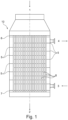
- the first cooling device 10 which is shown therein in a highly simplified schematic, is in principle designed as a type of tube bundle heat exchanger, which comprises a number of tubes 8 arranged approximately parallel to one another and, for example, approximately vertically. These tubes 11 run between an upper tube plate 6 and a lower tube plate 7 of the cooling device.
- the hot nitrogen oxide-containing gas which has its origin in the oxidation of ammonia in oxygen-containing gas, enters the first cooling device 10 through an upper tube-side nozzle 1.
- the cooled nitrogen-containing gas and the acid condensate formed by the cooling flow downwards out of the tubes 8 of the cooling device 10 and leave the cooling device through the lower nozzle 2, which in the present example has approximately the same diameter as the jacket of the cooling device 10 itself.
- this dimensioning is not a necessary feature of the arrangement.
- the cooling medium in this example fully demineralized water (VE water), which is to be used to generate steam, flows through the first cooling device 10 shown.
- the DE water enters the lower shell-side nozzle 3 of the first cooling device 10 at a temperature of, for example, 45 °C, which is below the dew point of the gas containing nitrogen oxide.
- the DE water is passed back and forth through several deflection plates 5 so that it is repeatedly passed over the pipes 8 in which the hot medium flows. With each deflection, the DE water rises in the first cooling device 10 and at the same time the temperature of the DE water rises.
- the amount of demineralized water and the total heat exchange surface of the cooling device are matched to the amount, composition and temperature of the incoming nitrogen oxide-containing gas so that the temperature of the demineralized water exceeds the dew point of the incoming nitrogen oxide-containing gas when it reaches the space between the top baffle plate 5 and the upper tube plate 6 of the first cooling device 10. This prevents the formation of condensate on the upper tube plate 6.
- the demineralized water leaves the first cooling device 10 through the upper, approximately horizontal nozzle 4, which is attached radially on the outside, for example, at a temperature of, for example, approximately 120 °C.
- the single tube is shown in abbreviated form here and one can see the upper tube plate 6 at the upper end of the tube 8 and the lower tube plate 7 at the lower end of the tube, into which the tube is embedded.
- the gas containing nitrogen oxide enters the top of the tube 8 at a temperature of, for example, 190 °C.
- the temperature of the upper tube plate 6 of the first cooling device 10 is between the temperature of the gas containing nitrogen oxide (e.g. 190 °C) and that of the deionized water (e.g. 120 °C).
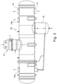
- a second cooling device 20 which, as can be seen from Figure 3 can be seen, is arranged under the first cooling device 10.
- the nitrogen oxide-containing gas and the condensate are cooled on the shell side of a horizontal tube bundle heat exchanger against cooling water on the tube side.
- the remaining nitrogen oxide-containing gas flows upwards from one or more upper nozzles 10a of the second cooling device 20 provided for this purpose, while the acid condensate flows downwards in the direction of arrow 11 from one or more lower nozzles 16 provided for this purpose.
- the cooling device 20 shown is a container which is, for example, cylindrical in its basic form, but whose axis is aligned approximately horizontally, so that it is virtually is a horizontal container whose axis runs transversely to the axis of the first cooling device 10.
- the latter is arranged, for example, approximately centrally on the top side of the second cooling device 20, so that condensate running off from the first cooling device 10 in a mixture with as yet uncondensed hot gas flows via the nozzle 2 from above in the direction of the arrow into the second cooling device, almost radially.
- the hot gas mixture flows vertically through the tubes of the tube bundle heat exchanger and the coolant flows outside in the jacket area of the device, in the second cooling device 20 it is the other way round.
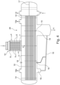
- the gas flowing in vertically via the pipe nozzle 2 in a mixture with condensate reaches the jacket of the second cooling device, so that finally the cooled acid condensate flows downwards via the lower nozzle 16 in the direction of the arrow from this jacket area of the cooling device 20.
- the coolant flows in the second cooling device 20 through a plurality of approximately parallel individual tubes of a second tube bundle heat exchanger. The coolant thus flows in the axial direction between two tube plates 14, in each of which the ends of the individual tubes of the tube bundle heat exchanger are fixed.
- the coolant therefore flows in the second cooling device in an approximately horizontal direction.
- An improved heat exchange with the hot mixture of gas and condensate entering at the top via the nozzle 2 takes place in that baffles 15 are also installed in the second cooling device 20, which here run vertically and at a distance from one another, so that the hot mixture of gas and condensate flows in a roughly meandering manner from the center, where it enters, to both sides, flowing alternately downwards and upwards and repeatedly coming into contact with the tubes through which the coolant flows.
- baffles that direct the gas upwards i.e. those that occupy the lower part of the shell, have an opening at or near the lowest point so that condensate can flow under the respective baffle towards one of the nozzles 16, or these baffles are not flush with the inner wall of the shell so that the gap between the baffle and the shell is large enough for the condensate to flow unhindered towards a nozzle 16.
- a smaller nozzle 16 is provided on the left, through which condensate can be collected and then passed via a connecting line 18 to the larger nozzle 16, from where it flows downwards out of the second cooling device.
- the nitrogen oxide-containing gas however, after it has passed the last deflector plate 15, rises upwards in the end regions of the interior in front of the tube plates 14 and flows out of the second cooling device 20 upwards via the two nozzles 10a arranged at the top.
- the coolant enters the Figure 4 right-hand area into the container of the second cooling device 20 via the lower inlet nozzle 12, where it enters at a low temperature. From there, it flows through a first number of lower parallel tubes of the tube bundle heat exchanger in an axial direction and thus horizontally to the left in the drawing to beyond the left tube plate 14. There it can flow back again in a horizontal direction (to the right in the drawing) via a second number of tubes (here there are a total of four upper tubes) to the right tube plate 14, where it reaches an upper chamber for coolant, which is separated from a lower chamber for coolant by a horizontal partition 17, for example.
- the lower inlet nozzle 12 has a fluid connection only to the lower chamber, where the coolant can only rise to the height of the partition 17.
- the upper chamber above the partition is provided with an outlet nozzle 13 on the top, so that the heated coolant can flow out of the second cooling device 20 there.
- the cooling side is designed with two threads. Other designs with, for example, single-thread or four-thread cooling are possible.
- the temperature conditions in the two cooling devices 10 and 20 connected in series in terms of flow are selected such that partial cooling and partial condensation of the hot gas mixture takes place in the first cooling device 10, whereby there is practically only a vertical flow of gas and condensate in the first cooling device.
- the gas already partially cooled gas-condensate mixture enters the second cooling device 20 the gas already has a significantly lower temperature due to the previous cooling.
- the temperature of the gas flow entering the first cooling device 10 via the upper pipe-side nozzle 1 is, for example, approximately 190 °C.
- the pressure of the gas is, for example, approximately 4 bara.
- the dew point of the nitrogen oxide-containing gas at which acid condensate begins to form is, for example, approximately 95 °C.
- the temperature of the gas flow and acid condensate flow exiting the first cooling device 10 via the nozzle 2 is, for example, approximately 125 °C. If then If acid condensate in the second cooling device 20 should reach a point where it cannot flow away freely, the temperature of the nitrogen oxide-containing gas at 125 °C is already too low to cause corrosion of this second cooling device to any significant extent by heating up the acid condensate.
Landscapes
- Chemical & Material Sciences (AREA)
- Chemical Kinetics & Catalysis (AREA)
- Organic Chemistry (AREA)
- Engineering & Computer Science (AREA)
- Inorganic Chemistry (AREA)
- Physics & Mathematics (AREA)
- Thermal Sciences (AREA)
- Mechanical Engineering (AREA)
- General Engineering & Computer Science (AREA)
- Heat-Exchange Devices With Radiators And Conduit Assemblies (AREA)
- Physical Or Chemical Processes And Apparatus (AREA)
Claims (2)
- Procédé de condensation contrôlée d'un mélange gazeux acide chaud, notamment de gaz contenant des oxydes d'azote lors de la production d'acide nitrique à partir d'ammoniac par oxydation avec de l'air ou un gaz oxydant, dans lequel, dans un premier dispositif de refroidissement (10), le mélange gazeux chaud est refroidi et condensé au moyen d'un agent réfrigérant, le mélange gazeux chaud étant refroidi de manière fluide dans le premier dispositif de refroidissement (10) au moyen d'un échangeur de chaleur dans un courant descendant orienté essentiellement verticalement dans une mesure telle que le point de rosée du mélange gazeux soit au moins partiellement dépassé vers le bas, le mélange déjà partiellement condensé sortant du premier dispositif de refroidissement (10) arrivant dans un deuxième dispositif de refroidissement (20) dans lequel il est encore refroidi, le deuxième dispositif de refroidissement étant agencé en dessous du premier dispositif de refroidissement, le mélange déjà partiellement condensé entrant dans le deuxième dispositif de refroidissement (20) dans un courant orienté essentiellement verticalement vers le bas, caractérisé en ce que le premier dispositif de refroidissement (10) est configuré sous forme d'échangeur de chaleur à faisceau de tubes avec une pluralité de tubes agencés essentiellement parallèlement les uns aux autres et les tubes (8) de l'échangeur de chaleur à faisceau de tubes du premier dispositif de refroidissement (10) sont agencés essentiellement verticalement, le deuxième dispositif de refroidissement (20) étant conçu sous forme essentiellement cylindrique et son axe étant essentiellement transversal à l'axe du premier dispositif de refroidissement, et en ce que le premier dispositif de refroidissement (10) présente une plaque tubulaire supérieure (6) et les conditions de traitement sont choisies de telle sorte que la température de cette plaque tubulaire supérieure (6) soit supérieure au point de rosée du mélange gazeux chaud.
- Procédé selon la revendication 1, caractérisé en ce que, dans le deuxième dispositif de refroidissement (20), une séparation de phases est effectuée en une solution d'acide nitrique faible sortant vers le bas par une tubulure et en un mélange gazeux contenant des NOx sortant vers le haut par au moins une tubulure.
Applications Claiming Priority (1)
| Application Number | Priority Date | Filing Date | Title |
|---|---|---|---|
| DE102016217765.6A DE102016217765A1 (de) | 2016-09-16 | 2016-09-16 | Anordnung und Verfahren zur Kondensation eines heißen sauren Gasgemischs |
Publications (3)
| Publication Number | Publication Date |
|---|---|
| EP3296676A1 EP3296676A1 (fr) | 2018-03-21 |
| EP3296676B1 EP3296676B1 (fr) | 2021-06-30 |
| EP3296676B2 true EP3296676B2 (fr) | 2024-08-28 |
Family
ID=59846390
Family Applications (1)
| Application Number | Title | Priority Date | Filing Date |
|---|---|---|---|
| EP17189725.9A Active EP3296676B2 (fr) | 2016-09-16 | 2017-09-07 | Arrangement et procédé de condensation d'un mélange acide chaud |
Country Status (3)
| Country | Link |
|---|---|
| EP (1) | EP3296676B2 (fr) |
| DE (1) | DE102016217765A1 (fr) |
| ES (1) | ES2886956T5 (fr) |
Families Citing this family (1)
| Publication number | Priority date | Publication date | Assignee | Title |
|---|---|---|---|---|
| CN114562905A (zh) * | 2022-01-25 | 2022-05-31 | 杭州制氧机集团股份有限公司 | 一种间壁式与接触式组合的冷却装置 |
Citations (1)
| Publication number | Priority date | Publication date | Assignee | Title |
|---|---|---|---|---|
| WO2013165246A1 (fr) † | 2012-05-03 | 2013-11-07 | Stamicarbon B.V. | Procédé et appareil de production d'urée à partir d'ammoniac et de dioxyde de carbone |
Family Cites Families (15)
| Publication number | Priority date | Publication date | Assignee | Title |
|---|---|---|---|---|
| US1814010A (en) * | 1925-02-27 | 1931-07-14 | Diamond Power Speciality | Air heater |
| GB456446A (en) | 1934-02-20 | 1936-11-09 | Du Pont | Improvements in and relating to the production of concentrated nitric acid |
| GB652346A (en) * | 1948-12-16 | 1951-04-18 | Thomas William Worsdale | Apparatus for heating air |
| DE1419190A1 (de) * | 1959-04-28 | 1968-11-21 | Gea Luftkuehler Happel Gmbh | Verfahren und Vorrichtung zur Kondensation von insbesondere chemischen Dampfgemischen |
| FR1285548A (fr) * | 1961-03-13 | 1962-02-23 | Escher Wyss Sa Soc | Réfrigérant préalable ou intermédiaire pour installation de turbine à gaz |
| US3568764A (en) | 1969-09-05 | 1971-03-09 | Daniel J Newman | Heat exchanger |
| FR2093411A5 (fr) * | 1970-06-12 | 1972-01-28 | Ugine Kuhlmann | |
| DE2716702A1 (de) | 1977-04-15 | 1979-01-04 | Herbert Ing Grad Sauerborn | Rohrbuendel-waermetauscher aus glas mit mehrgaengigen umlenkhauben |
| JPS5750954A (en) * | 1980-09-12 | 1982-03-25 | Mitsui Toatsu Chem Inc | Synthesis of urea |
| NL8502228A (nl) * | 1985-08-12 | 1987-03-02 | Unie Van Kunstmestfab Bv | Werkwijze voor de bereiding van ureum. |
| AU4090600A (en) | 1999-06-30 | 2001-01-04 | Rohm And Haas Company | High performance heat exchangers |
| DE10011335A1 (de) | 2000-03-10 | 2001-09-20 | Krupp Uhde Gmbh | Verfahren zur Herstellung von Salpetersäure |
| DE102005032797B4 (de) | 2005-07-14 | 2007-07-05 | Outokumpu Technology Oy | Verfahren und Anlage zur sicheren Kondensation von reinem SO3 aus Schwefeltrioxid enthaltenden Ausgangsgasen |
| DE102007006889B3 (de) * | 2007-02-13 | 2008-04-24 | Uhde Gmbh | Verfahren und Einrichtung zur Verhinderung der Korrosion an einem Gaseintrittsstutzen bei Salpetersäurekondensation |
| DE102014018261A1 (de) * | 2014-12-11 | 2016-06-16 | Borsig Gmbh | Quenchkühlsystem |
-
2016
- 2016-09-16 DE DE102016217765.6A patent/DE102016217765A1/de not_active Ceased
-
2017
- 2017-09-07 ES ES17189725T patent/ES2886956T5/es active Active
- 2017-09-07 EP EP17189725.9A patent/EP3296676B2/fr active Active
Patent Citations (1)
| Publication number | Priority date | Publication date | Assignee | Title |
|---|---|---|---|---|
| WO2013165246A1 (fr) † | 2012-05-03 | 2013-11-07 | Stamicarbon B.V. | Procédé et appareil de production d'urée à partir d'ammoniac et de dioxyde de carbone |
Non-Patent Citations (8)
| Title |
|---|
| "Shell and tube heat exchanger ", WIKIPEDIA, 5 June 2016 (2016-06-05), Retrieved from the Internet <URL:https://en.wikipedia.org/w/index.php?title=Shell_and_tube_heat_exchanger&oldid=723880888> † |
| "Ullmann's Encyclopedia of industrial chemistry", 1 January 2012, Weinheim , article MICHAEL THIEMANN ET AL.: "Nitric Acid, Nitrous Acid, and Nitrogen Oxides", pages: 177 - 225 † |
| Austin, D. G. "Chemical Engineering Drawing Symbols" Halsted Press, 1979 particular relevance pages 3-5 † |
| GROVES MICHAEL C.E., SASONOW ALEXANDER: "Uhde EnviNO x ® technology for NO X and N 2 O abatement: a contribution to reducing emissions from nitric acid plants", JOURNAL OF INTEGRATIVE ENVIRONMENTAL SCIENCES, vol. 7, no. sup1, 1 August 2010 (2010-08-01), pages 211 - 222, ISSN: 1943-815X, DOI: 10.1080/19438151003621334 † |
| MAURER R: "New Technological Concept for Nitric Acid: The Compact Nitric Acid Plant ", 8 April 2000 (2000-04-08), Retrieved from the Internet <URL:http://www.diquima.upm.es/old_diquima/docencia/tqi/docs/nitricac_cmpct.pdf> † |
| Presentation by Prof. Dr. Hartmut Wesenfeld (available from 2015) † |
| Screen print from opening the D2 file with Foxit pdf editor/reader, and selecting File>Properties † |
| THYSSENKRUPP: "Nitric Acid", BROCHURE, 22 January 2009 (2009-01-22), pages 1 - 20 † |
Also Published As
| Publication number | Publication date |
|---|---|
| ES2886956T5 (en) | 2025-02-24 |
| ES2886956T3 (es) | 2021-12-21 |
| EP3296676A1 (fr) | 2018-03-21 |
| EP3296676B1 (fr) | 2021-06-30 |
| DE102016217765A1 (de) | 2018-03-22 |
Similar Documents
| Publication | Publication Date | Title |
|---|---|---|
| EP1542778A1 (fr) | Plateau de transfert de matiere a courant transversal pourvu d'un systeme d'etancheite hydraulique | |
| DE102005036870A1 (de) | Verfahren zur Gasphasenphosgenierung | |
| DE1203226B (de) | Vorrichtung zur Abscheidung sublimierbarer Substanzen | |
| DE102004012293A1 (de) | Verfahren und Anlage zur Herstellung von Schwefelsäure | |
| DE19549139A1 (de) | Verfahren und Apparateanordnung zur Aufwärmung und mehrstufigen Entgasung von Wasser | |
| EP3296676B2 (fr) | Arrangement et procédé de condensation d'un mélange acide chaud | |
| DE602005003216T2 (de) | Vorrichtung zur verarbeitung von hochkorrosiven mitteln | |
| WO2014009346A1 (fr) | Dispositif et procédé de préparation du phosgène | |
| EP3124433B1 (fr) | Procédé de refroidissement de gaz de synthèse | |
| DE2913947C2 (de) | Vorrichtung zur Konzentrierung von verdünnter Schwefel- oder Phosphorsäure | |
| WO2018019534A1 (fr) | Dispositif de séparation d'eau produite présente dans de l'eau brute contaminée et procédé permettant de faire fonctionner ledit dispositif | |
| DE1668856C3 (de) | Verfahren und Vorrichtung zur Gewinnung einer kleiner als 1,O Gewichtsprozent Wasser enthaltenden Harnstoffschmelze | |
| DE202016104687U1 (de) | Kondensator | |
| DE2419096A1 (de) | Verfahren und vorrichtung zur vermeidung von korrosion in einem mehrstufigen kontakt-absorptionsprozess zur herstellung von schwefelsaeure | |
| DE3538515C2 (fr) | ||
| EP3737904B1 (fr) | Échangeur de chaleur à faisceau tubulaire présentant une protection anticorrosion | |
| DE2510294A1 (de) | Verfahren zum abtrennen von so tief 2 aus gasstroemen unter gewinnung von schwefelsaeure nach dem stickoxid-verfahren | |
| DE1109723B (de) | Senkrecht angeordneter Waermetauscher ohne Rohrplatten | |
| EP3320967B1 (fr) | Procédé et dispositif pour empêcher la corrosion d'une tubulure d'entrée de gaz lors d'une condensation d'acide nitrique | |
| DE19852894B4 (de) | Verfahren zur Gewinnung von Phthalsäureanhydrid durch katalytische Gasphasenreaktion und Vorrichtung zur Durchführung des Verfahrens | |
| DE202019106564U1 (de) | Staubabscheider und Verdampfungstrockner | |
| DE1501380A1 (de) | Verfahren und Vorrichtung zum Waermeaustausch zwischen Gasen,Daempfen,Fluessigkeiten und/oder festen Stoffen einerseits und festen oder fluessigen Waermetraegern andererseits | |
| DE1083235B (de) | Vorrichtung fuer die partielle Verbrennung von Kohlenwasserstoffen zu Wasserstoff und Kohlenoxyd enthaltenden Gasgemischen | |
| DE3106973C2 (de) | Luftgekühlte Kondensationsanlage | |
| EP4327906A1 (fr) | Dispositif à condensateur et séparateur intégrés |
Legal Events
| Date | Code | Title | Description |
|---|---|---|---|
| PUAI | Public reference made under article 153(3) epc to a published international application that has entered the european phase |
Free format text: ORIGINAL CODE: 0009012 |
|
| STAA | Information on the status of an ep patent application or granted ep patent |
Free format text: STATUS: THE APPLICATION HAS BEEN PUBLISHED |
|
| AK | Designated contracting states |
Kind code of ref document: A1 Designated state(s): AL AT BE BG CH CY CZ DE DK EE ES FI FR GB GR HR HU IE IS IT LI LT LU LV MC MK MT NL NO PL PT RO RS SE SI SK SM TR |
|
| AX | Request for extension of the european patent |
Extension state: BA ME |
|
| RAP1 | Party data changed (applicant data changed or rights of an application transferred) |
Owner name: THYSSENKRUPP INDUSTRIAL SOLUTIONS AG Owner name: THYSSENKRUPP AG |
|
| STAA | Information on the status of an ep patent application or granted ep patent |
Free format text: STATUS: REQUEST FOR EXAMINATION WAS MADE |
|
| 17P | Request for examination filed |
Effective date: 20180921 |
|
| RBV | Designated contracting states (corrected) |
Designated state(s): AL AT BE BG CH CY CZ DE DK EE ES FI FR GB GR HR HU IE IS IT LI LT LU LV MC MK MT NL NO PL PT RO RS SE SI SK SM TR |
|
| RIC1 | Information provided on ipc code assigned before grant |
Ipc: F28D 7/16 20060101ALI20201125BHEP Ipc: C01B 21/28 20060101ALI20201125BHEP Ipc: B01D 5/00 20060101ALI20201125BHEP Ipc: C01B 21/26 20060101ALI20201125BHEP Ipc: B01J 19/00 20060101ALN20201125BHEP Ipc: F28D 21/00 20060101ALN20201125BHEP Ipc: F28D 7/00 20060101AFI20201125BHEP |
|
| GRAP | Despatch of communication of intention to grant a patent |
Free format text: ORIGINAL CODE: EPIDOSNIGR1 |
|
| STAA | Information on the status of an ep patent application or granted ep patent |
Free format text: STATUS: GRANT OF PATENT IS INTENDED |
|
| INTG | Intention to grant announced |
Effective date: 20210125 |
|
| GRAS | Grant fee paid |
Free format text: ORIGINAL CODE: EPIDOSNIGR3 |
|
| GRAA | (expected) grant |
Free format text: ORIGINAL CODE: 0009210 |
|
| STAA | Information on the status of an ep patent application or granted ep patent |
Free format text: STATUS: THE PATENT HAS BEEN GRANTED |
|
| AK | Designated contracting states |
Kind code of ref document: B1 Designated state(s): AL AT BE BG CH CY CZ DE DK EE ES FI FR GB GR HR HU IE IS IT LI LT LU LV MC MK MT NL NO PL PT RO RS SE SI SK SM TR |
|
| REG | Reference to a national code |
Ref country code: CH Ref legal event code: EP |
|
| REG | Reference to a national code |
Ref country code: AT Ref legal event code: REF Ref document number: 1406714 Country of ref document: AT Kind code of ref document: T Effective date: 20210715 |
|
| REG | Reference to a national code |
Ref country code: DE Ref legal event code: R096 Ref document number: 502017010766 Country of ref document: DE |
|
| REG | Reference to a national code |
Ref country code: IE Ref legal event code: FG4D Free format text: LANGUAGE OF EP DOCUMENT: GERMAN |
|
| REG | Reference to a national code |
Ref country code: NO Ref legal event code: T2 Effective date: 20210630 |
|
| REG | Reference to a national code |
Ref country code: LT Ref legal event code: MG9D |
|
| PG25 | Lapsed in a contracting state [announced via postgrant information from national office to epo] |
Ref country code: HR Free format text: LAPSE BECAUSE OF FAILURE TO SUBMIT A TRANSLATION OF THE DESCRIPTION OR TO PAY THE FEE WITHIN THE PRESCRIBED TIME-LIMIT Effective date: 20210630 Ref country code: BG Free format text: LAPSE BECAUSE OF FAILURE TO SUBMIT A TRANSLATION OF THE DESCRIPTION OR TO PAY THE FEE WITHIN THE PRESCRIBED TIME-LIMIT Effective date: 20210930 Ref country code: FI Free format text: LAPSE BECAUSE OF FAILURE TO SUBMIT A TRANSLATION OF THE DESCRIPTION OR TO PAY THE FEE WITHIN THE PRESCRIBED TIME-LIMIT Effective date: 20210630 |
|
| PG25 | Lapsed in a contracting state [announced via postgrant information from national office to epo] |
Ref country code: RS Free format text: LAPSE BECAUSE OF FAILURE TO SUBMIT A TRANSLATION OF THE DESCRIPTION OR TO PAY THE FEE WITHIN THE PRESCRIBED TIME-LIMIT Effective date: 20210630 Ref country code: SE Free format text: LAPSE BECAUSE OF FAILURE TO SUBMIT A TRANSLATION OF THE DESCRIPTION OR TO PAY THE FEE WITHIN THE PRESCRIBED TIME-LIMIT Effective date: 20210630 Ref country code: LV Free format text: LAPSE BECAUSE OF FAILURE TO SUBMIT A TRANSLATION OF THE DESCRIPTION OR TO PAY THE FEE WITHIN THE PRESCRIBED TIME-LIMIT Effective date: 20210630 Ref country code: GR Free format text: LAPSE BECAUSE OF FAILURE TO SUBMIT A TRANSLATION OF THE DESCRIPTION OR TO PAY THE FEE WITHIN THE PRESCRIBED TIME-LIMIT Effective date: 20211001 |
|
| REG | Reference to a national code |
Ref country code: ES Ref legal event code: FG2A Ref document number: 2886956 Country of ref document: ES Kind code of ref document: T3 Effective date: 20211221 |
|
| REG | Reference to a national code |
Ref country code: NL Ref legal event code: FP |
|
| PG25 | Lapsed in a contracting state [announced via postgrant information from national office to epo] |
Ref country code: EE Free format text: LAPSE BECAUSE OF FAILURE TO SUBMIT A TRANSLATION OF THE DESCRIPTION OR TO PAY THE FEE WITHIN THE PRESCRIBED TIME-LIMIT Effective date: 20210630 Ref country code: RO Free format text: LAPSE BECAUSE OF FAILURE TO SUBMIT A TRANSLATION OF THE DESCRIPTION OR TO PAY THE FEE WITHIN THE PRESCRIBED TIME-LIMIT Effective date: 20210630 Ref country code: PT Free format text: LAPSE BECAUSE OF FAILURE TO SUBMIT A TRANSLATION OF THE DESCRIPTION OR TO PAY THE FEE WITHIN THE PRESCRIBED TIME-LIMIT Effective date: 20211102 Ref country code: SM Free format text: LAPSE BECAUSE OF FAILURE TO SUBMIT A TRANSLATION OF THE DESCRIPTION OR TO PAY THE FEE WITHIN THE PRESCRIBED TIME-LIMIT Effective date: 20210630 Ref country code: SK Free format text: LAPSE BECAUSE OF FAILURE TO SUBMIT A TRANSLATION OF THE DESCRIPTION OR TO PAY THE FEE WITHIN THE PRESCRIBED TIME-LIMIT Effective date: 20210630 |
|
| PG25 | Lapsed in a contracting state [announced via postgrant information from national office to epo] |
Ref country code: PL Free format text: LAPSE BECAUSE OF FAILURE TO SUBMIT A TRANSLATION OF THE DESCRIPTION OR TO PAY THE FEE WITHIN THE PRESCRIBED TIME-LIMIT Effective date: 20210630 |
|
| REG | Reference to a national code |
Ref country code: DE Ref legal event code: R026 Ref document number: 502017010766 Country of ref document: DE |
|
| PLBI | Opposition filed |
Free format text: ORIGINAL CODE: 0009260 |
|
| PLAX | Notice of opposition and request to file observation + time limit sent |
Free format text: ORIGINAL CODE: EPIDOSNOBS2 |
|
| PG25 | Lapsed in a contracting state [announced via postgrant information from national office to epo] |
Ref country code: DK Free format text: LAPSE BECAUSE OF FAILURE TO SUBMIT A TRANSLATION OF THE DESCRIPTION OR TO PAY THE FEE WITHIN THE PRESCRIBED TIME-LIMIT Effective date: 20210630 |
|
| 26 | Opposition filed |
Opponent name: STAMICARBON B.V. Effective date: 20220330 |
|
| REG | Reference to a national code |
Ref country code: BE Ref legal event code: MM Effective date: 20210930 |
|
| GBPC | Gb: european patent ceased through non-payment of renewal fee |
Effective date: 20210930 |
|
| PG25 | Lapsed in a contracting state [announced via postgrant information from national office to epo] |
Ref country code: MC Free format text: LAPSE BECAUSE OF FAILURE TO SUBMIT A TRANSLATION OF THE DESCRIPTION OR TO PAY THE FEE WITHIN THE PRESCRIBED TIME-LIMIT Effective date: 20210630 Ref country code: AL Free format text: LAPSE BECAUSE OF FAILURE TO SUBMIT A TRANSLATION OF THE DESCRIPTION OR TO PAY THE FEE WITHIN THE PRESCRIBED TIME-LIMIT Effective date: 20210630 |
|
| PG25 | Lapsed in a contracting state [announced via postgrant information from national office to epo] |
Ref country code: LU Free format text: LAPSE BECAUSE OF NON-PAYMENT OF DUE FEES Effective date: 20210907 Ref country code: IE Free format text: LAPSE BECAUSE OF NON-PAYMENT OF DUE FEES Effective date: 20210907 Ref country code: GB Free format text: LAPSE BECAUSE OF NON-PAYMENT OF DUE FEES Effective date: 20210930 Ref country code: BE Free format text: LAPSE BECAUSE OF NON-PAYMENT OF DUE FEES Effective date: 20210930 |
|
| PLBB | Reply of patent proprietor to notice(s) of opposition received |
Free format text: ORIGINAL CODE: EPIDOSNOBS3 |
|
| PG25 | Lapsed in a contracting state [announced via postgrant information from national office to epo] |
Ref country code: LT Free format text: LAPSE BECAUSE OF FAILURE TO SUBMIT A TRANSLATION OF THE DESCRIPTION OR TO PAY THE FEE WITHIN THE PRESCRIBED TIME-LIMIT Effective date: 20210630 |
|
| PG25 | Lapsed in a contracting state [announced via postgrant information from national office to epo] |
Ref country code: HU Free format text: LAPSE BECAUSE OF FAILURE TO SUBMIT A TRANSLATION OF THE DESCRIPTION OR TO PAY THE FEE WITHIN THE PRESCRIBED TIME-LIMIT; INVALID AB INITIO Effective date: 20170907 |
|
| PG25 | Lapsed in a contracting state [announced via postgrant information from national office to epo] |
Ref country code: CY Free format text: LAPSE BECAUSE OF FAILURE TO SUBMIT A TRANSLATION OF THE DESCRIPTION OR TO PAY THE FEE WITHIN THE PRESCRIBED TIME-LIMIT Effective date: 20210630 |
|
| P01 | Opt-out of the competence of the unified patent court (upc) registered |
Effective date: 20230530 |
|
| REG | Reference to a national code |
Ref country code: DE Ref legal event code: R081 Ref document number: 502017010766 Country of ref document: DE Owner name: THYSSENKRUPP UHDE GMBH, DE Free format text: FORMER OWNERS: THYSSENKRUPP AG, 45143 ESSEN, DE; THYSSENKRUPP INDUSTRIAL SOLUTIONS AG, 45143 ESSEN, DE Ref country code: DE Ref legal event code: R081 Ref document number: 502017010766 Country of ref document: DE Owner name: THYSSENKRUPP AG, DE Free format text: FORMER OWNERS: THYSSENKRUPP AG, 45143 ESSEN, DE; THYSSENKRUPP INDUSTRIAL SOLUTIONS AG, 45143 ESSEN, DE |
|
| REG | Reference to a national code |
Ref country code: AT Ref legal event code: MM01 Ref document number: 1406714 Country of ref document: AT Kind code of ref document: T Effective date: 20220907 |
|
| PG25 | Lapsed in a contracting state [announced via postgrant information from national office to epo] |
Ref country code: AT Free format text: LAPSE BECAUSE OF NON-PAYMENT OF DUE FEES Effective date: 20220907 |
|
| RAP2 | Party data changed (patent owner data changed or rights of a patent transferred) |
Owner name: THYSSENKRUPP AG Owner name: THYSSENKRUPP UHDE GMBH |
|
| PG25 | Lapsed in a contracting state [announced via postgrant information from national office to epo] |
Ref country code: MK Free format text: LAPSE BECAUSE OF FAILURE TO SUBMIT A TRANSLATION OF THE DESCRIPTION OR TO PAY THE FEE WITHIN THE PRESCRIBED TIME-LIMIT Effective date: 20210630 |
|
| PG25 | Lapsed in a contracting state [announced via postgrant information from national office to epo] |
Ref country code: TR Free format text: LAPSE BECAUSE OF FAILURE TO SUBMIT A TRANSLATION OF THE DESCRIPTION OR TO PAY THE FEE WITHIN THE PRESCRIBED TIME-LIMIT Effective date: 20210630 |
|
| PUAH | Patent maintained in amended form |
Free format text: ORIGINAL CODE: 0009272 |
|
| STAA | Information on the status of an ep patent application or granted ep patent |
Free format text: STATUS: PATENT MAINTAINED AS AMENDED |
|
| 27A | Patent maintained in amended form |
Effective date: 20240828 |
|
| AK | Designated contracting states |
Kind code of ref document: B2 Designated state(s): AL AT BE BG CH CY CZ DE DK EE ES FI FR GB GR HR HU IE IS IT LI LT LU LV MC MK MT NL NO PL PT RO RS SE SI SK SM TR |
|
| REG | Reference to a national code |
Ref country code: DE Ref legal event code: R102 Ref document number: 502017010766 Country of ref document: DE |
|
| PG25 | Lapsed in a contracting state [announced via postgrant information from national office to epo] |
Ref country code: MT Free format text: LAPSE BECAUSE OF FAILURE TO SUBMIT A TRANSLATION OF THE DESCRIPTION OR TO PAY THE FEE WITHIN THE PRESCRIBED TIME-LIMIT Effective date: 20210630 |
|
| REG | Reference to a national code |
Ref country code: NL Ref legal event code: FP |
|
| REG | Reference to a national code |
Ref country code: ES Ref legal event code: DC2A Ref document number: 2886956 Country of ref document: ES Kind code of ref document: T5 Effective date: 20250224 |
|
| REG | Reference to a national code |
Ref country code: CH Ref legal event code: U11 Free format text: ST27 STATUS EVENT CODE: U-0-0-U10-U11 (AS PROVIDED BY THE NATIONAL OFFICE) Effective date: 20251001 |
|
| PGFP | Annual fee paid to national office [announced via postgrant information from national office to epo] |
Ref country code: DE Payment date: 20250919 Year of fee payment: 9 |
|
| PGFP | Annual fee paid to national office [announced via postgrant information from national office to epo] |
Ref country code: NO Payment date: 20250923 Year of fee payment: 9 |
|
| PGFP | Annual fee paid to national office [announced via postgrant information from national office to epo] |
Ref country code: IT Payment date: 20250923 Year of fee payment: 9 Ref country code: NL Payment date: 20250918 Year of fee payment: 9 |
|
| PGFP | Annual fee paid to national office [announced via postgrant information from national office to epo] |
Ref country code: FR Payment date: 20250922 Year of fee payment: 9 |
|
| PGFP | Annual fee paid to national office [announced via postgrant information from national office to epo] |
Ref country code: CZ Payment date: 20250903 Year of fee payment: 9 |
|
| PGFP | Annual fee paid to national office [announced via postgrant information from national office to epo] |
Ref country code: CH Payment date: 20251001 Year of fee payment: 9 |
|
| PGFP | Annual fee paid to national office [announced via postgrant information from national office to epo] |
Ref country code: ES Payment date: 20251028 Year of fee payment: 9 |