EP3296700A1 - Procédé de détermination de la position d'un capteur de position d'un système de mesure de position - Google Patents
Procédé de détermination de la position d'un capteur de position d'un système de mesure de position Download PDFInfo
- Publication number
- EP3296700A1 EP3296700A1 EP17167135.7A EP17167135A EP3296700A1 EP 3296700 A1 EP3296700 A1 EP 3296700A1 EP 17167135 A EP17167135 A EP 17167135A EP 3296700 A1 EP3296700 A1 EP 3296700A1
- Authority
- EP
- European Patent Office
- Prior art keywords
- matrix
- vector
- forming
- vectors
- steps
- Prior art date
- Legal status (The legal status is an assumption and is not a legal conclusion. Google has not performed a legal analysis and makes no representation as to the accuracy of the status listed.)
- Granted
Links
Images


Classifications
-
- G—PHYSICS
- G01—MEASURING; TESTING
- G01D—MEASURING NOT SPECIALLY ADAPTED FOR A SPECIFIC VARIABLE; ARRANGEMENTS FOR MEASURING TWO OR MORE VARIABLES NOT COVERED IN A SINGLE OTHER SUBCLASS; TARIFF METERING APPARATUS; MEASURING OR TESTING NOT OTHERWISE PROVIDED FOR
- G01D18/00—Testing or calibrating apparatus or arrangements provided for in groups G01D1/00 - G01D15/00
- G01D18/001—Calibrating encoders
-
- G—PHYSICS
- G01—MEASURING; TESTING
- G01B—MEASURING LENGTH, THICKNESS OR SIMILAR LINEAR DIMENSIONS; MEASURING ANGLES; MEASURING AREAS; MEASURING IRREGULARITIES OF SURFACES OR CONTOURS
- G01B7/00—Measuring arrangements characterised by the use of electric or magnetic techniques
- G01B7/003—Measuring arrangements characterised by the use of electric or magnetic techniques for measuring position, not involving coordinate determination
-
- G—PHYSICS
- G01—MEASURING; TESTING
- G01D—MEASURING NOT SPECIALLY ADAPTED FOR A SPECIFIC VARIABLE; ARRANGEMENTS FOR MEASURING TWO OR MORE VARIABLES NOT COVERED IN A SINGLE OTHER SUBCLASS; TARIFF METERING APPARATUS; MEASURING OR TESTING NOT OTHERWISE PROVIDED FOR
- G01D5/00—Mechanical means for transferring the output of a sensing member; Means for converting the output of a sensing member to another variable where the form or nature of the sensing member does not constrain the means for converting; Transducers not specially adapted for a specific variable
- G01D5/12—Mechanical means for transferring the output of a sensing member; Means for converting the output of a sensing member to another variable where the form or nature of the sensing member does not constrain the means for converting; Transducers not specially adapted for a specific variable using electric or magnetic means
- G01D5/14—Mechanical means for transferring the output of a sensing member; Means for converting the output of a sensing member to another variable where the form or nature of the sensing member does not constrain the means for converting; Transducers not specially adapted for a specific variable using electric or magnetic means influencing the magnitude of a current or voltage
-
- G—PHYSICS
- G01—MEASURING; TESTING
- G01B—MEASURING LENGTH, THICKNESS OR SIMILAR LINEAR DIMENSIONS; MEASURING ANGLES; MEASURING AREAS; MEASURING IRREGULARITIES OF SURFACES OR CONTOURS
- G01B21/00—Measuring arrangements or details thereof, where the measuring technique is not covered by the other groups of this subclass, unspecified or not relevant
-
- G—PHYSICS
- G01—MEASURING; TESTING
- G01D—MEASURING NOT SPECIALLY ADAPTED FOR A SPECIFIC VARIABLE; ARRANGEMENTS FOR MEASURING TWO OR MORE VARIABLES NOT COVERED IN A SINGLE OTHER SUBCLASS; TARIFF METERING APPARATUS; MEASURING OR TESTING NOT OTHERWISE PROVIDED FOR
- G01D5/00—Mechanical means for transferring the output of a sensing member; Means for converting the output of a sensing member to another variable where the form or nature of the sensing member does not constrain the means for converting; Transducers not specially adapted for a specific variable
- G01D5/12—Mechanical means for transferring the output of a sensing member; Means for converting the output of a sensing member to another variable where the form or nature of the sensing member does not constrain the means for converting; Transducers not specially adapted for a specific variable using electric or magnetic means
- G01D5/14—Mechanical means for transferring the output of a sensing member; Means for converting the output of a sensing member to another variable where the form or nature of the sensing member does not constrain the means for converting; Transducers not specially adapted for a specific variable using electric or magnetic means influencing the magnitude of a current or voltage
- G01D5/142—Mechanical means for transferring the output of a sensing member; Means for converting the output of a sensing member to another variable where the form or nature of the sensing member does not constrain the means for converting; Transducers not specially adapted for a specific variable using electric or magnetic means influencing the magnitude of a current or voltage using Hall-effect devices
- G01D5/145—Mechanical means for transferring the output of a sensing member; Means for converting the output of a sensing member to another variable where the form or nature of the sensing member does not constrain the means for converting; Transducers not specially adapted for a specific variable using electric or magnetic means influencing the magnitude of a current or voltage using Hall-effect devices influenced by the relative movement between the Hall device and magnetic fields
-
- G—PHYSICS
- G01—MEASURING; TESTING
- G01D—MEASURING NOT SPECIALLY ADAPTED FOR A SPECIFIC VARIABLE; ARRANGEMENTS FOR MEASURING TWO OR MORE VARIABLES NOT COVERED IN A SINGLE OTHER SUBCLASS; TARIFF METERING APPARATUS; MEASURING OR TESTING NOT OTHERWISE PROVIDED FOR
- G01D5/00—Mechanical means for transferring the output of a sensing member; Means for converting the output of a sensing member to another variable where the form or nature of the sensing member does not constrain the means for converting; Transducers not specially adapted for a specific variable
- G01D5/12—Mechanical means for transferring the output of a sensing member; Means for converting the output of a sensing member to another variable where the form or nature of the sensing member does not constrain the means for converting; Transducers not specially adapted for a specific variable using electric or magnetic means
- G01D5/244—Mechanical means for transferring the output of a sensing member; Means for converting the output of a sensing member to another variable where the form or nature of the sensing member does not constrain the means for converting; Transducers not specially adapted for a specific variable using electric or magnetic means influencing characteristics of pulses or pulse trains; generating pulses or pulse trains
- G01D5/24471—Error correction
- G01D5/24476—Signal processing
-
- H—ELECTRICITY
- H02—GENERATION; CONVERSION OR DISTRIBUTION OF ELECTRIC POWER
- H02K—DYNAMO-ELECTRIC MACHINES
- H02K11/00—Structural association of dynamo-electric machines with electric components or with devices for shielding, monitoring or protection
- H02K11/20—Structural association of dynamo-electric machines with electric components or with devices for shielding, monitoring or protection for measuring, monitoring, testing, protecting or switching
- H02K11/21—Devices for sensing speed or position, or actuated thereby
- H02K11/215—Magnetic effect devices, e.g. Hall-effect or magneto-resistive elements
-
- H—ELECTRICITY
- H02—GENERATION; CONVERSION OR DISTRIBUTION OF ELECTRIC POWER
- H02P—CONTROL OR REGULATION OF ELECTRIC MOTORS, ELECTRIC GENERATORS OR DYNAMO-ELECTRIC CONVERTERS; CONTROLLING TRANSFORMERS, REACTORS OR CHOKE COILS
- H02P6/00—Arrangements for controlling synchronous motors or other dynamo-electric motors using electronic commutation dependent on the rotor position; Electronic commutators therefor
- H02P6/14—Electronic commutators
- H02P6/16—Circuit arrangements for detecting position
Definitions
- the invention relates to methods for determining the position of a position sensor of a position measuring system, in particular a method for determining the position of the position sensor of a linear position measuring system or the position sensor of an angle measuring system.
- a fundamental difficulty with these methods is that a non-ideal arrangement of position sensor and sensor chip leads to distortions of the raw measurement signals, in particular that they no longer have the pure sine and cosine shape and thus lead to an inaccurate determination of the position ⁇ .
- There are methods to improve the raw signal quality eg by applying offset and amplitude corrections.
- a known method for a sensor arrangement with two sensors is based on a description of the measuring points as ellipses and requires specific calibration measurements, which provide parameters for the corrections and can only be realized in practice with considerable effort. This method requires great care in the design of the sensor arrangement and especially in the adjustment of the permanent magnet, so that the measured values are sufficiently accurate on an ellipse. If the actual axis of rotation does not pass through the magnetically defined center of the permanent magnet, the correction may even cause the opposite effect of increasing the angular error.
- a position sensing system will respond to extraneous fields (e.g., the earth's magnetic field in the case of a permanent magnet based positioner). Without countermeasures, these additional field components can not be distinguished from the useful field, so that the external fields limit the accuracy of the position measuring system.
- extraneous fields e.g., the earth's magnetic field in the case of a permanent magnet based positioner.
- a fundamental challenge for position measuring systems is their long-term stability, ie an initially sufficiently accurate calibration changes over time, for example, by mechanical displacement of the components relative to one another or by drifting of electronic sensor properties.
- the measurement quality of systems during operation can not be determined according to the prior art; in particular, this can not be determined intrinsically, ie without reference measurement of happened outside.
- an intrinsic method would be of great importance for fault-tolerant systems.
- a recalibration of a position measuring system during operation would also be very valuable in order to decisively improve the long-term stability.
- the method according to the invention for determining the position of a position sensor is based on the knowledge that the sensor measured values supplied by the sensors are used as the measuring vector, i. can be represented as a point in a vector space whose dimension corresponds to the number of sensors, and that the measurement vectors generated during the movement of the position sensor (rotation about an axis of rotation or displacement along an axis) lie in an orbital trajectory in this vector space.
- This orbit can - under ideal conditions - be projected onto a circle or arc by means of a linear image. That each position of the locator corresponds to a point on the orbit in the abstract space of the signal vectors, which is uniquely associated with a point on the circle.
- Non-ideal conditions for example non-ideal characteristics of the position sensor, which may be the case in particular with magnets, or too small a number of sensors or the use of incorrectly selected calibration positions, cause deviations from the circular shape.
- the linear mapping can be represented as a matrix vector operation and can be determined using standard methods of linear algebra. Each measurement vector is projected onto a 2-element vector, the peak of which lies approximately on a circle or circular arc, the direction of the 2-element vector corresponding to the position of the position indicator.
- the linear mapping is determined in a calibration phase, which involves the acquisition of measurement vectors and the decomposition of a matrix formed by the measurement vectors into two or typically three matrices.
- the representation of the measured values supplied by the sensors as a vector also makes it possible to reduce the influence of extraneous fields, in particular magnetic extraneous fields, with a further linear image.
- the inventive method is universally applicable.
- the arrangement of the sensors is almost arbitrary.
- the sensors may even detect different components of the field generated by the position sensor.
- the determination of the matrix can be carried out by means of measurements which have to meet only an absolute minimum of conditions.
- the method does not require a large number of angle reference measurements, except for the determination of the zero position, which however requires only a single reference measurement.
- the Fig. 1 shows a position measuring system having a rotatable about a predetermined axis of rotation 1 2 and a sensor chip 3.
- the rotational position of the magnet 2 is the position ⁇ to be determined by means of the sensor chip 3.
- the sensor chip 3 is on the right side of the Fig. 1 enlarged reproduced.
- the sensor chip 3 comprises a predetermined number of 1 to r sensors 4 and electronic circuits for the operation of the sensors, etc.
- the sensors 4 are, for example, Hall sensors. Such a sensor 4 may also be a cluster of several individual sensors which provide a common output signal.
- the sensor chip 3 may also contain magnetic field concentrators which amplify the magnetic field generated by the magnet 2 at the locations of the sensors 4.
- the sensors 4 each emit a sensor signal.
- the sensor signals are referred to here as a 1 to a r .
- the index j of the sensor signal a j so is the number of
- the Fig. 2 shows a position measuring system, which is formed of a magnet 2 and a sensor chip 3, which are displaceable relative to each other along a linear axis x .
- the sensor chip 3 comprises a predetermined number of 1 to r sensors 4 and electronic circuits for the operation of the sensors, etc.
- the sensors are eg Hall sensors.
- the magnet 2 consists of alternately oppositely magnetized regions which generate a periodically changing magnetic field at the locations of the sensors 4 when displaced along the axis x.
- the x position of the magnet 2 is the position ⁇ to be determined by means of the sensor chip 3.
- x D / 2 ⁇ ⁇ ⁇ , where D is a predetermined distance by the magnet 2.
- the sensors 4 of these position measuring systems deliver harmonic output signals as a result of the periodically changing magnetic field.
- the position measuring system of Fig. 1 is an angle measuring system with the rotatable magnet 2 as a position sensor.
- the position measuring system of Fig. 2 is a linear measuring system with the sliding magnet 2 as a position sensor.
- the rotor coil R is rotatable about an axis of rotation and is supplied with a sinusoidal current which generates a magnetic field.
- Position measuring systems can also be based on the inductive principle, in which at least one transmitting coil and at least one receiving coil are spatially fixed and the position transmitter is a geometrically structured, electrically conductive disc rotatable about an axis. It is also possible to use the same coil for the transmission and the reception process.
- the coils can be arranged on several levels and / or interconnected.
- the position measuring system may have two or more coils. The use of multiple coils is particularly helpful to detect the full 360 ° rotation.
- the position sensor changes the inductance of the transmitting and Receiving coil (s).
- the transmitting coils are supplied with alternating currents, preferably sinusoidal currents, the magnetic fields generated thereby inducing voltages in the receiving coils which have harmonic varying amplitudes due to the position-dependent eddy currents generated in the disc.
- alternating currents preferably sinusoidal currents
- the inventive method is also useful in optical position measuring systems, in which two or more optical sensors (eg phototransistors, photodiodes, etc.) depending on the position of an optically active position sensor brightness, polarization, phase shift, time of ("time of flight ”) or other optical property variations.
- the position transmitter reflects or modulates a light beam and thus causes the harmonic signals used by the method.
- the optical field such a position meter can continue with radar or Terrahertzstrahlungssensoren, resp. corresponding position sensors are realized.
- sound waves in particular ultrasound, can also be used instead of optical and electromagnetic waves and a corresponding position measuring system can be constructed.
- the method according to the invention can also be used in electrostatic position measuring systems in which a rotatably mounted, geometrically structured electrode as position transmitter together with stator electrodes forms two or more capacitors with position-dependent capacitances. In the process, capacitive signals varying in a harmonious manner with the position are generated and recorded.
- the locator may also be realized by a patterned dielectric material that modulates the capacitance of two or more spatially fixed electrode pairs in harmony with the position.
- the inventive method also makes it possible to separate the useful signal or the useful signals of interference signals.
- a magnetic encoder on an electric motor called.
- the magnetic field of the magnetic angle sensor can be cleanly separated from the rotating fields of the electric motor.
- the position can be determined trouble-free.
- optical, electromagnetic, electrical, magnetic, and acoustic position determinations are examples of optical, electromagnetic, electrical, magnetic, and acoustic position determinations.
- the invention relates to a method with which the position ⁇ can be calculated from the measured values supplied by the sensors 4, without the position of the sensor chip 3 playing a role with respect to the axis of rotation 1 or to the linear axis x .
- the method may be a simple method, ie a method without offset correction and without an external field correction, or a method with offset correction or a method with external field correction or a method with offset and field correction.
- the method includes in all cases a calibration phase and normal operation.
- the offset correction takes place by means of an offset vector a 0 .
- the external field correction takes place by means of a projection matrix P.
- the offset and external field correction takes place by means of the offset vector a 0 and the projection matrix P.
- the offset vector a 0 and the projection matrix P are determined in the calibration phase.
- a matrix M is determined in each case.
- the measuring vectors q thus have a number of n components, with 2 ⁇ n ⁇ r .
- the positions ⁇ k which are in the range of 0 to 2 ⁇ , are shown here as angles, as is the case with an angle measuring system. However, the positions ⁇ k of the position sensor can also lie on a linear axis.
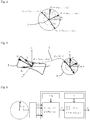
- the arrows illustrate the position ⁇ k of the position sensor , each position ⁇ k is a signal vector a k assigned.
- the left side illustrates the space of the measurement vectors q
- the right side shows the plane with the circle 6 and the 2 vectors p
- Exemplary is the illustration of q 3 on p 3 indicated by an arrow.
- Every measurement vector q k is a vector p k assigned whose direction encloses an angle with a reference direction, which corresponds to the position ⁇ k of the position sensor.
- the offset vector will also be used a 0 and possibly the projection matrix P in the same way determined by interpolation of the corresponding objects at the temperature support points.
- This variant offers the advantage that in this way both temperature effects, which influence the mechanical position of the position sensor relative to the sensor chip, as well as temperature-dependent effects in the sensors can be compensated.
- the vector p contains the complete information about the position ⁇ to be determined.
- the function f ( p ), for example, the function f ( p ) atan2 ( p 2 , p 1 ), where atan2 ( p 2 , p 1 ) is a function known from many programming languages that provides the correct angle in the range of 0 to 2 ⁇ .
- the offset vector a 0 can be determined in a conventional, known manner.
- the determination of the matrix M takes place in the calibration phase.
- the first method is based on ensuring "from the outside” that calibration positions are selected that are distributed over the entire measurement range and allow an accurate result.
- the second method is a bootstrap process that is started with a factory setting and then iteratively generates better calibration positions.
- the Fig. 7 illustrates the determination of the projection matrix P in the calibration phase.
- the signal vectors a j ( a j 1 , ..., a jr ) .
- the orthonormal basis G 1 , ..., G c of the foreign field vectors f j spanned subspace formed.
- the projection matrix P is computed by obtaining from the unit matrix the matrices obtained as tensor products from the basis vectors G j ⁇ G j be subtracted.
- the Fig. 8 illustrates the determination of the matrix M in the calibration phase.
- the measurement vectors thus obtained q k form the Lines of the matrix Q.
- the matrix Q is then decomposed into the three matrices ⁇ , S and ⁇ T. In dependence on the predetermined parameter h, the sub-matrices U, V, T and S of U, V and S are determined. With the auxiliary matrices T and N then the matrix M is calculated.
- the individual iterations adaptively lead to improved matrices M ( i ) , because in each step more precise positions ⁇ of the cached measurement vectors q can be determined, so that the matrix Q according to the predetermined criterion from more suitable measurement vectors q is formed and thus leads to a more accurate matrix M.
- the desired direction of rotation is already contained in the start matrix M and does not change during the iterations.
- a large number of measuring vectors improves the calibration with poor uniform distribution of the positions ⁇ .
- the position of the sensor chip 3 may change in the course of time relative to the position of the axis of rotation 1 or the axis x .
- the method can be extended by a plausibility check if the dimension n of the vector space of the measurement vectors is n> 2.
- the method requires a further n ⁇ n matrix C , which is determined in the calibration phase and used for the plausibility check in normal operation.
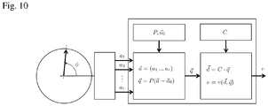
- the Fig. 9 illustrates the determination of the matrix C in the calibration phase. This calculation proceeds to the determination of the three matrices U, S and V T analogous to the determination of the matrix M. The matrix C is then calculated by subtracting from the unit matrix the product of the sub-matrix ⁇ of the matrix V with its transposed ⁇ T.
- the Fig. 10 illustrates the plausibility check. This check is carried out in normal operation. The calculation is up to the determination of q analogous to the calculation of the position ( Fig. 6 ). For the plausibility check, the measurement vector becomes q by means of the matrix C, the n- component vector d and from this finally the test variable v is calculated.
- This method allows the separation of extraneous field detection and position determination in a manner that eliminates the need to precisely position and match the sensors in sensitivity, and does not require separation in sensors for determining position and in sensors for detecting External fields is required.
Landscapes
- Physics & Mathematics (AREA)
- General Physics & Mathematics (AREA)
- Engineering & Computer Science (AREA)
- Power Engineering (AREA)
- Signal Processing (AREA)
- Microelectronics & Electronic Packaging (AREA)
- Transmission And Conversion Of Sensor Element Output (AREA)
- Measurement Of Length, Angles, Or The Like Using Electric Or Magnetic Means (AREA)
- Complex Calculations (AREA)
- Length Measuring Devices With Unspecified Measuring Means (AREA)
- Control Of Motors That Do Not Use Commutators (AREA)
Priority Applications (5)
| Application Number | Priority Date | Filing Date | Title |
|---|---|---|---|
| EP17180252.3A EP3296701B1 (fr) | 2016-09-16 | 2017-07-07 | Dispositif de détection destiné à déterminer la position du rotor d'une machine électrique et organe de commande pour un moteur électrique |
| JP2017161531A JP7097013B2 (ja) | 2016-09-16 | 2017-08-24 | 位置測定システムの位置表示器の位置を決定するための方法 |
| US15/694,798 US10557722B2 (en) | 2016-09-16 | 2017-09-03 | System for determining the position of the position indicator of a position measuring system |
| US15/694,800 US10663319B2 (en) | 2016-09-16 | 2017-09-03 | Sensor device for determining the position of the rotor of an electrical machine and control device for an electric motor |
| CN201710827663.4A CN107830792B (zh) | 2016-09-16 | 2017-09-14 | 用于确定位置测量系统的位置指示器的位置的方法 |
Applications Claiming Priority (1)
| Application Number | Priority Date | Filing Date | Title |
|---|---|---|---|
| CH01207/16A CH712932A2 (de) | 2016-09-16 | 2016-09-16 | Verfahren zur Bestimmung der Position eines Positionsgebers eines Positionsmesssystems. |
Publications (3)
| Publication Number | Publication Date |
|---|---|
| EP3296700A1 true EP3296700A1 (fr) | 2018-03-21 |
| EP3296700B1 EP3296700B1 (fr) | 2018-08-29 |
| EP3296700B8 EP3296700B8 (fr) | 2018-10-17 |
Family
ID=58579034
Family Applications (2)
| Application Number | Title | Priority Date | Filing Date |
|---|---|---|---|
| EP17167135.7A Active EP3296700B8 (fr) | 2016-09-16 | 2017-04-19 | Procédé de détermination de la position d'un capteur de position d'un système de mesure de position |
| EP17180252.3A Active EP3296701B1 (fr) | 2016-09-16 | 2017-07-07 | Dispositif de détection destiné à déterminer la position du rotor d'une machine électrique et organe de commande pour un moteur électrique |
Family Applications After (1)
| Application Number | Title | Priority Date | Filing Date |
|---|---|---|---|
| EP17180252.3A Active EP3296701B1 (fr) | 2016-09-16 | 2017-07-07 | Dispositif de détection destiné à déterminer la position du rotor d'une machine électrique et organe de commande pour un moteur électrique |
Country Status (5)
| Country | Link |
|---|---|
| US (2) | US10557722B2 (fr) |
| EP (2) | EP3296700B8 (fr) |
| JP (1) | JP7097013B2 (fr) |
| CN (1) | CN107830792B (fr) |
| CH (1) | CH712932A2 (fr) |
Families Citing this family (15)
| Publication number | Priority date | Publication date | Assignee | Title |
|---|---|---|---|---|
| DE102017216536B4 (de) * | 2017-09-19 | 2023-07-06 | Vitesco Technologies GmbH | Verfahren zur Kompensation von Störungen eines gemessenen Winkelsignals eines magnetischen Winkelsensors einer elektrischen Maschine und ein entsprechend ausgebildeter Mikrokontroller, eine elektrische Maschine, sowie ein Computerprogrammprodukt |
| CN108830868B (zh) * | 2018-04-19 | 2021-07-16 | 江南大学 | 一种基于Snake模型和迭代极性转换回归结合的圆弧拟合方法 |
| EP4614112A3 (fr) * | 2018-06-26 | 2025-12-03 | Melexis Technologies SA | Système et procédé de capteur de position, robustes contre les champs perturbateurs |
| CN109165576B (zh) * | 2018-08-07 | 2021-09-28 | 南京邮电大学 | 一种运动状态识别方法及装置 |
| DE102018222842A1 (de) * | 2018-12-21 | 2020-06-25 | Robert Bosch Gmbh | Motoranordnung mit Lagesensor |
| CN110207769B (zh) * | 2019-07-06 | 2020-10-02 | 三川智慧科技股份有限公司 | 一种可检测及修正数据误差的线圈感应式水表 |
| DE102020102065B3 (de) * | 2020-01-29 | 2021-06-02 | Schaeffler Technologies AG & Co. KG | Kupplungsaktor, Erfassungssystem und Verfahren zur Erfassung einer Winkelposition eines Drehbauteils |
| NL2025181B1 (en) * | 2020-03-20 | 2021-10-20 | Tecnotion Assets B V | Electric AC synchronous motor |
| EP4009003B1 (fr) | 2020-12-02 | 2024-05-29 | NM Numerical Modelling GmbH | Système de capteur et méthode de mesure d'une valeur de procédé d'un système physique |
| CN117203501A (zh) * | 2021-01-13 | 2023-12-08 | 塞弗德公司 | n相位置编码器及相关的信号处理方法和校准方法 |
| KR20230150302A (ko) * | 2021-02-03 | 2023-10-30 | 모트엑스 엘티디. | 고해상도 절대형 벡터 인코더 |
| CN113029204B (zh) * | 2021-03-01 | 2023-06-23 | 歌尔微电子股份有限公司 | 传感器和电子设备 |
| EP4276418B1 (fr) | 2022-05-09 | 2025-08-13 | NM Numerical Modelling GmbH | Dispositif capteur et procédé pour déterminer une position angulaire relative entre les moitiés d'arbre d'un arbre rotatif |
| EP4279875A1 (fr) * | 2022-05-18 | 2023-11-22 | Siemens Aktiengesellschaft | Système de capteur, moteur électrique pourvu de système de capteur et procédé de mesure d'un angle d'un moteur électrique |
| JP2023171993A (ja) | 2022-05-23 | 2023-12-06 | 国立大学法人 東京大学 | 情報処理装置、情報分析システム及び計測方法 |
Citations (4)
| Publication number | Priority date | Publication date | Assignee | Title |
|---|---|---|---|---|
| WO2002065247A2 (fr) * | 2001-02-14 | 2002-08-22 | Gregory Gould | Procede permettant d'estimer la precision d'un dispositif |
| WO2005124286A1 (fr) | 2004-06-19 | 2005-12-29 | Robert Bosch Gmbh | Procede et dispositif pour corriger un systeme de detection mesurant un angle et/ou une distance |
| US20110067479A1 (en) * | 2009-09-22 | 2011-03-24 | Gm Global Technology Operations, Inc. | System and method for calibrating a rotary absolute position sensor |
| US20150048242A1 (en) * | 2012-03-05 | 2015-02-19 | Gsi Group Corporation | Phase estimation method and apparatus therefor |
Family Cites Families (22)
| Publication number | Priority date | Publication date | Assignee | Title |
|---|---|---|---|---|
| US20030062889A1 (en) * | 1996-12-12 | 2003-04-03 | Synaptics (Uk) Limited | Position detector |
| DE59914974D1 (de) * | 1998-09-24 | 2009-04-23 | Levitronix Llc | Permanentmagnetisch erregter elektrischer Drehantrieb |
| JP3213292B2 (ja) * | 1999-07-12 | 2001-10-02 | ソニーケミカル株式会社 | 多層基板、及びモジュール |
| DE10034733B4 (de) * | 1999-08-02 | 2004-07-08 | Siemens Ag | Ermittlungsverfahren für ein Lagesignal und/oder für Korrekturwerte für Messsignale |
| GB2403017A (en) * | 2002-03-05 | 2004-12-22 | Synaptics | Position sensor |
| US6791219B1 (en) * | 2003-06-18 | 2004-09-14 | Bvr Technologies Company | Contactless electro-mechanical actuator with coupled electronic motor commutation and output position sensors |
| WO2006082047A1 (fr) * | 2005-02-01 | 2006-08-10 | Nctengineering Gmbh | Capteur de position et machine a laver |
| DE102006057062B4 (de) * | 2006-11-28 | 2010-12-02 | Siemens Ag | Verfahren und Einrichtung zum Messen des Pollagewinkels eines Magnetschwebefahrzeugs einer Magnetschwebebahn |
| DE102008030201A1 (de) * | 2007-07-25 | 2009-01-29 | Dr. Johannes Heidenhain Gmbh | Drehgeber und Verfahren zu dessen Betrieb |
| CN101476860B (zh) * | 2009-01-22 | 2011-07-20 | 中国科学院电工研究所 | 一种高背景磁场下的磁定位方法及装置 |
| US8248039B2 (en) * | 2009-06-30 | 2012-08-21 | Vestas Wind Systems A/S | Control system for an electrical generator and method for controlling an electrical generator |
| JP2011075404A (ja) * | 2009-09-30 | 2011-04-14 | Panasonic Corp | デジタルスケールの検出信号補正方法及び検出信号補正装置 |
| JP5542466B2 (ja) * | 2010-02-05 | 2014-07-09 | 日本電産サンキョー株式会社 | 磁気センサ装置 |
| JP5105263B2 (ja) * | 2010-03-29 | 2012-12-26 | 株式会社デンソー | 回転角度検出装置 |
| US8319089B2 (en) * | 2010-09-07 | 2012-11-27 | William Henry Morong | Oscillatory, magnetically activated position sensor |
| FR2977094B1 (fr) * | 2011-06-23 | 2013-07-12 | Alstom Hydro France | Methode de regulation de la puissance d'une installation de conversion d'energie et installation de conversion d'energie pilotee par une telle methode |
| DE102011079116A1 (de) * | 2011-07-14 | 2013-01-17 | Kuka Roboter Gmbh | Verfahren zum Überprüfen der Plausibilität der Ausgangssignale eines Resolvers |
| GB2483177B (en) * | 2011-10-19 | 2013-10-02 | Protean Electric Ltd | An electric motor or generator |
| EP3080627B1 (fr) * | 2013-12-26 | 2020-10-14 | Allegro MicroSystems, LLC | Procédés et appareil pour diagnostics de capteurs |
| JP2016053547A (ja) * | 2014-09-04 | 2016-04-14 | 旭化成エレクトロニクス株式会社 | 非接触回転角センサ及びそれに備えられた磁気センサ信号処理回路並びに磁気センサの他軸感度調整方法 |
| CN104677266B (zh) * | 2015-01-20 | 2017-11-10 | 江苏多维科技有限公司 | 强磁场误差校准的磁电阻角度传感器及其校准方法 |
| JP6624446B2 (ja) * | 2016-02-26 | 2019-12-25 | 株式会社東京精密 | 内挿方法及び内挿装置 |
-
2016
- 2016-09-16 CH CH01207/16A patent/CH712932A2/de not_active Application Discontinuation
-
2017
- 2017-04-19 EP EP17167135.7A patent/EP3296700B8/fr active Active
- 2017-07-07 EP EP17180252.3A patent/EP3296701B1/fr active Active
- 2017-08-24 JP JP2017161531A patent/JP7097013B2/ja active Active
- 2017-09-03 US US15/694,798 patent/US10557722B2/en active Active
- 2017-09-03 US US15/694,800 patent/US10663319B2/en active Active
- 2017-09-14 CN CN201710827663.4A patent/CN107830792B/zh active Active
Patent Citations (4)
| Publication number | Priority date | Publication date | Assignee | Title |
|---|---|---|---|---|
| WO2002065247A2 (fr) * | 2001-02-14 | 2002-08-22 | Gregory Gould | Procede permettant d'estimer la precision d'un dispositif |
| WO2005124286A1 (fr) | 2004-06-19 | 2005-12-29 | Robert Bosch Gmbh | Procede et dispositif pour corriger un systeme de detection mesurant un angle et/ou une distance |
| US20110067479A1 (en) * | 2009-09-22 | 2011-03-24 | Gm Global Technology Operations, Inc. | System and method for calibrating a rotary absolute position sensor |
| US20150048242A1 (en) * | 2012-03-05 | 2015-02-19 | Gsi Group Corporation | Phase estimation method and apparatus therefor |
Also Published As
| Publication number | Publication date |
|---|---|
| CH712932A2 (de) | 2018-03-29 |
| EP3296700B8 (fr) | 2018-10-17 |
| US20180080796A1 (en) | 2018-03-22 |
| EP3296700B1 (fr) | 2018-08-29 |
| CN107830792B (zh) | 2021-04-23 |
| CN107830792A (zh) | 2018-03-23 |
| JP7097013B2 (ja) | 2022-07-07 |
| US10663319B2 (en) | 2020-05-26 |
| US20180080797A1 (en) | 2018-03-22 |
| US10557722B2 (en) | 2020-02-11 |
| EP3296701B1 (fr) | 2020-11-18 |
| JP2018066724A (ja) | 2018-04-26 |
| EP3296701A1 (fr) | 2018-03-21 |
Similar Documents
| Publication | Publication Date | Title |
|---|---|---|
| EP3296700B1 (fr) | Procédé de détermination de la position d'un capteur de position d'un système de mesure de position | |
| DE102009046807B4 (de) | Verfahren zur Empfindlichkeitsbestimmung eines Beschleunigungs- oder Magnetfeldsensors | |
| DE102017106322B4 (de) | Magnetfelddetektor | |
| EP2603773B1 (fr) | Ensemble capteur et procédé pour déterminer une position spatiale d'une première pièce par rapport à une deuxième pièce | |
| EP2729768B1 (fr) | Calibrage et fonctionnement de dispositifs rotatifs, en particulier pour les têtes de détection et/ou les palpeurs des appareils de mesure de coordonnées | |
| DE102010028390B4 (de) | Verfahren zur Bestimmung eines Erregerleiterabstandes von einem Magnetfeldsensor, Verfahren zum Kalibrieren des Magnetfeldsensors sowie ein kalibrierbarer Magnetfeldsensor und Verwendung einer Erregerleiterstruktur zur Bestimmung eines Erregerleiterabstandes | |
| DE102017113861B4 (de) | Winkelsensor und Winkelsensorsystem | |
| DE102017204264B4 (de) | Elektromagnetischer Absolut-Positionsgeber | |
| DE102017105820A1 (de) | Korrekturvorrichtung für einen winkelsensor, und winkelsensor | |
| DE112014001449B4 (de) | Magnetischer Positionssensor und Positionserfassungsverfahren | |
| DE102017111979B4 (de) | Winkelsensor, Korrekturverfahren zur Verwendung mit dem Winkelsensor und Winkelsensorsystem | |
| DE102014115537B4 (de) | Schaltung und verfahren zum erhalten von informationen über eine physikalische grösse | |
| DE102017202217B4 (de) | Verfahren und Vorrichtung zur Korrektur eines Ausgangssignals einer Messeinrichtung | |
| DE102014103588A1 (de) | Magnetsensorsystem | |
| DE102017119668A1 (de) | Winkelsensor und Winkelsensorsystem | |
| DE102019131203A1 (de) | Winkelsensor und winkelsensorsystem | |
| DE4141000A1 (de) | Anordnung und verfahren zur messung von distanzen oder drehwinkeln | |
| DE102018118130A1 (de) | Offset-Schätzvorrichtung und -verfahren, Korrekturvorrichtung für einen Magnetsensor, und Stromsensor | |
| DE102021202134A1 (de) | Verfahren zur Bestimmung, Messung und/oder Überwachung von Eigenschaften eines Sensorsystems | |
| DE102017202218A1 (de) | Verfahren und Vorrichtung zur Korrektur eines Ausgangssignals einer Messeinrichtung | |
| EP2066997B1 (fr) | Mesure de distance par champ magnétique commandé | |
| DE102019119896A1 (de) | Korrekturvorrichtung für einen winkelsensor und winkelsensor | |
| DE102021125964A1 (de) | Ein Positionssensorsystem, ein optisches Linsensystem und eine Anzeige | |
| DE10247321B3 (de) | Verfahren zum Offsetabgleich einer Sensoranordnung zur Erfassung einer Bewegung oder eines Drehwinkels | |
| DE102023003366A1 (de) | Verfahren zur Kompensation von Winkelfehlern |
Legal Events
| Date | Code | Title | Description |
|---|---|---|---|
| PUAI | Public reference made under article 153(3) epc to a published international application that has entered the european phase |
Free format text: ORIGINAL CODE: 0009012 |
|
| STAA | Information on the status of an ep patent application or granted ep patent |
Free format text: STATUS: REQUEST FOR EXAMINATION WAS MADE |
|
| 17P | Request for examination filed |
Effective date: 20171128 |
|
| AK | Designated contracting states |
Kind code of ref document: A1 Designated state(s): AL AT BE BG CH CY CZ DE DK EE ES FI FR GB GR HR HU IE IS IT LI LT LU LV MC MK MT NL NO PL PT RO RS SE SI SK SM TR |
|
| AX | Request for extension of the european patent |
Extension state: BA ME |
|
| GRAP | Despatch of communication of intention to grant a patent |
Free format text: ORIGINAL CODE: EPIDOSNIGR1 |
|
| STAA | Information on the status of an ep patent application or granted ep patent |
Free format text: STATUS: GRANT OF PATENT IS INTENDED |
|
| INTG | Intention to grant announced |
Effective date: 20180612 |
|
| GRAS | Grant fee paid |
Free format text: ORIGINAL CODE: EPIDOSNIGR3 |
|
| RAP1 | Party data changed (applicant data changed or rights of an application transferred) |
Owner name: MAGLAB GMBH Owner name: NM NUMERCIAL MODELLING GMBH |
|
| GRAA | (expected) grant |
Free format text: ORIGINAL CODE: 0009210 |
|
| STAA | Information on the status of an ep patent application or granted ep patent |
Free format text: STATUS: THE PATENT HAS BEEN GRANTED |
|
| RBV | Designated contracting states (corrected) |
Designated state(s): AL AT BE BG CH CY CZ DE DK EE ES FI FR GB GR HR HU IE IS IT LI LT LU LV MC MK MT NL NO PL PT RO RS SE SI SK SM TR |
|
| AK | Designated contracting states |
Kind code of ref document: B1 Designated state(s): AL AT BE BG CH CY CZ DE DK EE ES FI FR GB GR HR HU IE IS IT LI LT LU LV MC MK MT NL NO PL PT RO RS SE SI SK SM TR |
|
| REG | Reference to a national code |
Ref country code: GB Ref legal event code: FG4D Free format text: NOT ENGLISH |
|
| REG | Reference to a national code |
Ref country code: CH Ref legal event code: EP |
|
| REG | Reference to a national code |
Ref country code: AT Ref legal event code: REF Ref document number: 1035660 Country of ref document: AT Kind code of ref document: T Effective date: 20180915 |
|
| RAP2 | Party data changed (patent owner data changed or rights of a patent transferred) |
Owner name: MAGLAB AG Owner name: NM NUMERCIAL MODELLING GMBH |
|
| REG | Reference to a national code |
Ref country code: IE Ref legal event code: FG4D Free format text: LANGUAGE OF EP DOCUMENT: GERMAN |
|
| REG | Reference to a national code |
Ref country code: CH Ref legal event code: PK Free format text: BERICHTIGUNG B8 |
|
| REG | Reference to a national code |
Ref country code: DE Ref legal event code: R096 Ref document number: 502017000139 Country of ref document: DE |
|
| REG | Reference to a national code |
Ref country code: NL Ref legal event code: MP Effective date: 20180829 |
|
| REG | Reference to a national code |
Ref country code: LT Ref legal event code: MG4D |
|
| PG25 | Lapsed in a contracting state [announced via postgrant information from national office to epo] |
Ref country code: FI Free format text: LAPSE BECAUSE OF FAILURE TO SUBMIT A TRANSLATION OF THE DESCRIPTION OR TO PAY THE FEE WITHIN THE PRESCRIBED TIME-LIMIT Effective date: 20180829 Ref country code: GR Free format text: LAPSE BECAUSE OF FAILURE TO SUBMIT A TRANSLATION OF THE DESCRIPTION OR TO PAY THE FEE WITHIN THE PRESCRIBED TIME-LIMIT Effective date: 20181130 Ref country code: NO Free format text: LAPSE BECAUSE OF FAILURE TO SUBMIT A TRANSLATION OF THE DESCRIPTION OR TO PAY THE FEE WITHIN THE PRESCRIBED TIME-LIMIT Effective date: 20181129 Ref country code: IS Free format text: LAPSE BECAUSE OF FAILURE TO SUBMIT A TRANSLATION OF THE DESCRIPTION OR TO PAY THE FEE WITHIN THE PRESCRIBED TIME-LIMIT Effective date: 20181229 Ref country code: RS Free format text: LAPSE BECAUSE OF FAILURE TO SUBMIT A TRANSLATION OF THE DESCRIPTION OR TO PAY THE FEE WITHIN THE PRESCRIBED TIME-LIMIT Effective date: 20180829 Ref country code: LT Free format text: LAPSE BECAUSE OF FAILURE TO SUBMIT A TRANSLATION OF THE DESCRIPTION OR TO PAY THE FEE WITHIN THE PRESCRIBED TIME-LIMIT Effective date: 20180829 Ref country code: BG Free format text: LAPSE BECAUSE OF FAILURE TO SUBMIT A TRANSLATION OF THE DESCRIPTION OR TO PAY THE FEE WITHIN THE PRESCRIBED TIME-LIMIT Effective date: 20181129 Ref country code: NL Free format text: LAPSE BECAUSE OF FAILURE TO SUBMIT A TRANSLATION OF THE DESCRIPTION OR TO PAY THE FEE WITHIN THE PRESCRIBED TIME-LIMIT Effective date: 20180829 Ref country code: SE Free format text: LAPSE BECAUSE OF FAILURE TO SUBMIT A TRANSLATION OF THE DESCRIPTION OR TO PAY THE FEE WITHIN THE PRESCRIBED TIME-LIMIT Effective date: 20180829 |
|
| PG25 | Lapsed in a contracting state [announced via postgrant information from national office to epo] |
Ref country code: AL Free format text: LAPSE BECAUSE OF FAILURE TO SUBMIT A TRANSLATION OF THE DESCRIPTION OR TO PAY THE FEE WITHIN THE PRESCRIBED TIME-LIMIT Effective date: 20180829 Ref country code: LV Free format text: LAPSE BECAUSE OF FAILURE TO SUBMIT A TRANSLATION OF THE DESCRIPTION OR TO PAY THE FEE WITHIN THE PRESCRIBED TIME-LIMIT Effective date: 20180829 Ref country code: HR Free format text: LAPSE BECAUSE OF FAILURE TO SUBMIT A TRANSLATION OF THE DESCRIPTION OR TO PAY THE FEE WITHIN THE PRESCRIBED TIME-LIMIT Effective date: 20180829 |
|
| PG25 | Lapsed in a contracting state [announced via postgrant information from national office to epo] |
Ref country code: IT Free format text: LAPSE BECAUSE OF FAILURE TO SUBMIT A TRANSLATION OF THE DESCRIPTION OR TO PAY THE FEE WITHIN THE PRESCRIBED TIME-LIMIT Effective date: 20180829 Ref country code: PL Free format text: LAPSE BECAUSE OF FAILURE TO SUBMIT A TRANSLATION OF THE DESCRIPTION OR TO PAY THE FEE WITHIN THE PRESCRIBED TIME-LIMIT Effective date: 20180829 Ref country code: EE Free format text: LAPSE BECAUSE OF FAILURE TO SUBMIT A TRANSLATION OF THE DESCRIPTION OR TO PAY THE FEE WITHIN THE PRESCRIBED TIME-LIMIT Effective date: 20180829 Ref country code: RO Free format text: LAPSE BECAUSE OF FAILURE TO SUBMIT A TRANSLATION OF THE DESCRIPTION OR TO PAY THE FEE WITHIN THE PRESCRIBED TIME-LIMIT Effective date: 20180829 Ref country code: ES Free format text: LAPSE BECAUSE OF FAILURE TO SUBMIT A TRANSLATION OF THE DESCRIPTION OR TO PAY THE FEE WITHIN THE PRESCRIBED TIME-LIMIT Effective date: 20180829 Ref country code: CZ Free format text: LAPSE BECAUSE OF FAILURE TO SUBMIT A TRANSLATION OF THE DESCRIPTION OR TO PAY THE FEE WITHIN THE PRESCRIBED TIME-LIMIT Effective date: 20180829 |
|
| REG | Reference to a national code |
Ref country code: CH Ref legal event code: NV Representative=s name: PATENTANWALTSBUERO DR. URS FALK, CH |
|
| PG25 | Lapsed in a contracting state [announced via postgrant information from national office to epo] |
Ref country code: DK Free format text: LAPSE BECAUSE OF FAILURE TO SUBMIT A TRANSLATION OF THE DESCRIPTION OR TO PAY THE FEE WITHIN THE PRESCRIBED TIME-LIMIT Effective date: 20180829 Ref country code: SK Free format text: LAPSE BECAUSE OF FAILURE TO SUBMIT A TRANSLATION OF THE DESCRIPTION OR TO PAY THE FEE WITHIN THE PRESCRIBED TIME-LIMIT Effective date: 20180829 Ref country code: SM Free format text: LAPSE BECAUSE OF FAILURE TO SUBMIT A TRANSLATION OF THE DESCRIPTION OR TO PAY THE FEE WITHIN THE PRESCRIBED TIME-LIMIT Effective date: 20180829 |
|
| REG | Reference to a national code |
Ref country code: DE Ref legal event code: R097 Ref document number: 502017000139 Country of ref document: DE |
|
| PLBE | No opposition filed within time limit |
Free format text: ORIGINAL CODE: 0009261 |
|
| STAA | Information on the status of an ep patent application or granted ep patent |
Free format text: STATUS: NO OPPOSITION FILED WITHIN TIME LIMIT |
|
| 26N | No opposition filed |
Effective date: 20190531 |
|
| PG25 | Lapsed in a contracting state [announced via postgrant information from national office to epo] |
Ref country code: SI Free format text: LAPSE BECAUSE OF FAILURE TO SUBMIT A TRANSLATION OF THE DESCRIPTION OR TO PAY THE FEE WITHIN THE PRESCRIBED TIME-LIMIT Effective date: 20180829 |
|
| REG | Reference to a national code |
Ref country code: BE Ref legal event code: MM Effective date: 20190430 |
|
| PG25 | Lapsed in a contracting state [announced via postgrant information from national office to epo] |
Ref country code: MC Free format text: LAPSE BECAUSE OF FAILURE TO SUBMIT A TRANSLATION OF THE DESCRIPTION OR TO PAY THE FEE WITHIN THE PRESCRIBED TIME-LIMIT Effective date: 20180829 Ref country code: LU Free format text: LAPSE BECAUSE OF NON-PAYMENT OF DUE FEES Effective date: 20190419 |
|
| PG25 | Lapsed in a contracting state [announced via postgrant information from national office to epo] |
Ref country code: BE Free format text: LAPSE BECAUSE OF NON-PAYMENT OF DUE FEES Effective date: 20190430 |
|
| PG25 | Lapsed in a contracting state [announced via postgrant information from national office to epo] |
Ref country code: TR Free format text: LAPSE BECAUSE OF FAILURE TO SUBMIT A TRANSLATION OF THE DESCRIPTION OR TO PAY THE FEE WITHIN THE PRESCRIBED TIME-LIMIT Effective date: 20180829 |
|
| PG25 | Lapsed in a contracting state [announced via postgrant information from national office to epo] |
Ref country code: IE Free format text: LAPSE BECAUSE OF NON-PAYMENT OF DUE FEES Effective date: 20190419 |
|
| PG25 | Lapsed in a contracting state [announced via postgrant information from national office to epo] |
Ref country code: PT Free format text: LAPSE BECAUSE OF FAILURE TO SUBMIT A TRANSLATION OF THE DESCRIPTION OR TO PAY THE FEE WITHIN THE PRESCRIBED TIME-LIMIT Effective date: 20181229 |
|
| PG25 | Lapsed in a contracting state [announced via postgrant information from national office to epo] |
Ref country code: CY Free format text: LAPSE BECAUSE OF FAILURE TO SUBMIT A TRANSLATION OF THE DESCRIPTION OR TO PAY THE FEE WITHIN THE PRESCRIBED TIME-LIMIT Effective date: 20180829 |
|
| PG25 | Lapsed in a contracting state [announced via postgrant information from national office to epo] |
Ref country code: HU Free format text: LAPSE BECAUSE OF FAILURE TO SUBMIT A TRANSLATION OF THE DESCRIPTION OR TO PAY THE FEE WITHIN THE PRESCRIBED TIME-LIMIT; INVALID AB INITIO Effective date: 20170419 Ref country code: MT Free format text: LAPSE BECAUSE OF FAILURE TO SUBMIT A TRANSLATION OF THE DESCRIPTION OR TO PAY THE FEE WITHIN THE PRESCRIBED TIME-LIMIT Effective date: 20180829 |
|
| GBPC | Gb: european patent ceased through non-payment of renewal fee |
Effective date: 20210419 |
|
| PG25 | Lapsed in a contracting state [announced via postgrant information from national office to epo] |
Ref country code: GB Free format text: LAPSE BECAUSE OF NON-PAYMENT OF DUE FEES Effective date: 20210419 |
|
| PG25 | Lapsed in a contracting state [announced via postgrant information from national office to epo] |
Ref country code: MK Free format text: LAPSE BECAUSE OF FAILURE TO SUBMIT A TRANSLATION OF THE DESCRIPTION OR TO PAY THE FEE WITHIN THE PRESCRIBED TIME-LIMIT Effective date: 20180829 |
|
| REG | Reference to a national code |
Ref country code: AT Ref legal event code: MM01 Ref document number: 1035660 Country of ref document: AT Kind code of ref document: T Effective date: 20220419 |
|
| PG25 | Lapsed in a contracting state [announced via postgrant information from national office to epo] |
Ref country code: AT Free format text: LAPSE BECAUSE OF NON-PAYMENT OF DUE FEES Effective date: 20220419 |
|
| PGFP | Annual fee paid to national office [announced via postgrant information from national office to epo] |
Ref country code: DE Payment date: 20250429 Year of fee payment: 9 |
|
| PGFP | Annual fee paid to national office [announced via postgrant information from national office to epo] |
Ref country code: FR Payment date: 20250425 Year of fee payment: 9 |
|
| PGFP | Annual fee paid to national office [announced via postgrant information from national office to epo] |
Ref country code: CH Payment date: 20250501 Year of fee payment: 9 |