EP3296765B1 - Laserradarvorrichtung und windgeschwindigkeitsbeobachtungsverfahren - Google Patents
Laserradarvorrichtung und windgeschwindigkeitsbeobachtungsverfahren Download PDFInfo
- Publication number
- EP3296765B1 EP3296765B1 EP15891818.5A EP15891818A EP3296765B1 EP 3296765 B1 EP3296765 B1 EP 3296765B1 EP 15891818 A EP15891818 A EP 15891818A EP 3296765 B1 EP3296765 B1 EP 3296765B1
- Authority
- EP
- European Patent Office
- Prior art keywords
- wind velocity
- wind
- spectrum
- unit
- calculating unit
- Prior art date
- Legal status (The legal status is an assumption and is not a legal conclusion. Google has not performed a legal analysis and makes no representation as to the accuracy of the status listed.)
- Active
Links
Images




Classifications
-
- G—PHYSICS
- G01—MEASURING; TESTING
- G01S—RADIO DIRECTION-FINDING; RADIO NAVIGATION; DETERMINING DISTANCE OR VELOCITY BY USE OF RADIO WAVES; LOCATING OR PRESENCE-DETECTING BY USE OF THE REFLECTION OR RERADIATION OF RADIO WAVES; ANALOGOUS ARRANGEMENTS USING OTHER WAVES
- G01S17/00—Systems using the reflection or reradiation of electromagnetic waves other than radio waves, e.g. lidar systems
- G01S17/02—Systems using the reflection of electromagnetic waves other than radio waves
- G01S17/06—Systems determining position data of a target
- G01S17/08—Systems determining position data of a target for measuring distance only
- G01S17/10—Systems determining position data of a target for measuring distance only using transmission of interrupted, pulse-modulated waves
- G01S17/18—Systems determining position data of a target for measuring distance only using transmission of interrupted, pulse-modulated waves wherein range gates are used
-
- G—PHYSICS
- G01—MEASURING; TESTING
- G01S—RADIO DIRECTION-FINDING; RADIO NAVIGATION; DETERMINING DISTANCE OR VELOCITY BY USE OF RADIO WAVES; LOCATING OR PRESENCE-DETECTING BY USE OF THE REFLECTION OR RERADIATION OF RADIO WAVES; ANALOGOUS ARRANGEMENTS USING OTHER WAVES
- G01S7/00—Details of systems according to groups G01S13/00, G01S15/00, G01S17/00
- G01S7/48—Details of systems according to groups G01S13/00, G01S15/00, G01S17/00 of systems according to group G01S17/00
- G01S7/483—Details of pulse systems
- G01S7/486—Receivers
- G01S7/487—Extracting wanted echo signals, e.g. pulse detection
-
- G—PHYSICS
- G01—MEASURING; TESTING
- G01P—MEASURING LINEAR OR ANGULAR SPEED, ACCELERATION, DECELERATION, OR SHOCK; INDICATING PRESENCE, ABSENCE, OR DIRECTION, OF MOVEMENT
- G01P5/00—Measuring speed of fluids, e.g. of air stream; Measuring speed of bodies relative to fluids, e.g. of ship, of aircraft
- G01P5/26—Measuring speed of fluids, e.g. of air stream; Measuring speed of bodies relative to fluids, e.g. of ship, of aircraft by measuring the direct influence of the streaming fluid on the properties of a detecting optical wave
-
- G—PHYSICS
- G01—MEASURING; TESTING
- G01S—RADIO DIRECTION-FINDING; RADIO NAVIGATION; DETERMINING DISTANCE OR VELOCITY BY USE OF RADIO WAVES; LOCATING OR PRESENCE-DETECTING BY USE OF THE REFLECTION OR RERADIATION OF RADIO WAVES; ANALOGOUS ARRANGEMENTS USING OTHER WAVES
- G01S17/00—Systems using the reflection or reradiation of electromagnetic waves other than radio waves, e.g. lidar systems
- G01S17/02—Systems using the reflection of electromagnetic waves other than radio waves
- G01S17/06—Systems determining position data of a target
- G01S17/42—Simultaneous measurement of distance and other co-ordinates
-
- G—PHYSICS
- G01—MEASURING; TESTING
- G01S—RADIO DIRECTION-FINDING; RADIO NAVIGATION; DETERMINING DISTANCE OR VELOCITY BY USE OF RADIO WAVES; LOCATING OR PRESENCE-DETECTING BY USE OF THE REFLECTION OR RERADIATION OF RADIO WAVES; ANALOGOUS ARRANGEMENTS USING OTHER WAVES
- G01S17/00—Systems using the reflection or reradiation of electromagnetic waves other than radio waves, e.g. lidar systems
- G01S17/02—Systems using the reflection of electromagnetic waves other than radio waves
- G01S17/50—Systems of measurement based on relative movement of target
- G01S17/58—Velocity or trajectory determination systems; Sense-of-movement determination systems
-
- G—PHYSICS
- G01—MEASURING; TESTING
- G01S—RADIO DIRECTION-FINDING; RADIO NAVIGATION; DETERMINING DISTANCE OR VELOCITY BY USE OF RADIO WAVES; LOCATING OR PRESENCE-DETECTING BY USE OF THE REFLECTION OR RERADIATION OF RADIO WAVES; ANALOGOUS ARRANGEMENTS USING OTHER WAVES
- G01S17/00—Systems using the reflection or reradiation of electromagnetic waves other than radio waves, e.g. lidar systems
- G01S17/88—Lidar systems specially adapted for specific applications
- G01S17/95—Lidar systems specially adapted for specific applications for meteorological use
-
- G—PHYSICS
- G01—MEASURING; TESTING
- G01S—RADIO DIRECTION-FINDING; RADIO NAVIGATION; DETERMINING DISTANCE OR VELOCITY BY USE OF RADIO WAVES; LOCATING OR PRESENCE-DETECTING BY USE OF THE REFLECTION OR RERADIATION OF RADIO WAVES; ANALOGOUS ARRANGEMENTS USING OTHER WAVES
- G01S7/00—Details of systems according to groups G01S13/00, G01S15/00, G01S17/00
- G01S7/48—Details of systems according to groups G01S13/00, G01S15/00, G01S17/00 of systems according to group G01S17/00
- G01S7/4808—Evaluating distance, position or velocity data
-
- Y—GENERAL TAGGING OF NEW TECHNOLOGICAL DEVELOPMENTS; GENERAL TAGGING OF CROSS-SECTIONAL TECHNOLOGIES SPANNING OVER SEVERAL SECTIONS OF THE IPC; TECHNICAL SUBJECTS COVERED BY FORMER USPC CROSS-REFERENCE ART COLLECTIONS [XRACs] AND DIGESTS
- Y02—TECHNOLOGIES OR APPLICATIONS FOR MITIGATION OR ADAPTATION AGAINST CLIMATE CHANGE
- Y02A—TECHNOLOGIES FOR ADAPTATION TO CLIMATE CHANGE
- Y02A90/00—Technologies having an indirect contribution to adaptation to climate change
- Y02A90/10—Information and communication technologies [ICT] supporting adaptation to climate change, e.g. for weather forecasting or climate simulation
Definitions
- the present invention relates to a laser radar apparatus for and a wind velocity observation method of observing wind velocities in an atmosphere.
- a radar apparatus As a device for measuring the position of an object that exists at a distant point, a radar apparatus is known.
- a radar apparatus emits a wave, such as an electromagnetic wave or acoustic wave, into space, receives a wave that is reflected from an observation object and returned back, and analyzes the returned wave to measure a distance from the radar apparatus to the object and an angle of the object.
- a wave such as an electromagnetic wave or acoustic wave
- a weather radar apparatus observes a very small aerosol floating in the atmosphere, and measures, as a wind velocity, a velocity at which an aerosol moves from an amount of phase rotation of a wave that is reflected from the aerosol and returned back.
- a laser radar apparatus using light as an electromagnetic wave is used as a wind direction and wind velocity radar because the laser radar apparatus has a very small divergence of a beam emitted and therefore can observe an object with a high angular resolution (for example, refer to Nonpatent Literature 1).
- a typical laser radar apparatus emits laser light into the atmosphere, after that, receives the laser light which is reflected by an aerosol in the atmosphere and then returns thereto, i.e., the laser light which has received a Doppler frequency shift that depends on the moving velocity of the aerosol in the atmosphere, and performs heterodyne detection on the laser light and local light, thereby detecting a Doppler signal corresponding to a wind velocity.
- Such a laser radar apparatus is generally called a Doppler lidar, and divides a laser light beam which is reflected by an aerosol at each altitude in the atmosphere and then returns thereto into laser light beams with respect to time, and performs coherent integration in very small spaces within each of range bins corresponding to the laser light beams separate with respect to time.
- the laser radar apparatus When performing the coherent integration within each of the range bins, the laser radar apparatus needs to shorten a unit time with which the laser radar apparatus divides the laser light beam in order to grasp spatial variations in wind velocities in detail, because the unit time with which the laser radar apparatus divides the laser light beam corresponds to the distance resolution.
- the signal amount acquired decreases when the time required for the coherent integration is shortened, there is a trade-off relationship between the time required for the coherent integration and the distance up to which observations can be performed, i.e., the distance becomes short with decrease in the time required for the coherent integration.
- a typical laser radar apparatus When acquiring a spectrum signal by performing coherent integration within each of the range bins, a typical laser radar apparatus specifies a Doppler shift amount which is a frequency at which the spectrum signal has a maximum, and calculates a wind velocity from the Doppler shift amount.
- noise may have a higher peak than the spectrum signal. Therefore, in the low SNR area, the peak of noise may be detected erroneously as the peak of the spectrum signal, and an incorrect wind velocity may be calculated.
- Patent Literature 3 a laser radar apparatus that, when searching for the peak of a spectrum signal, determines a standard deviation of wind velocities between the gate (distance) of a high SNR area and that of a low SNR area adjacent to the high SNR area, and determines a peak search scope within which to search for the peak of the spectrum signal by using the standard deviation is disclosed.
- the range within which to search for the peak of the spectrum signal is limited, the probability that the peak of noise is detected erroneously as the peak of the spectrum signal is decreased.
- US 2012/169052 A1 discloses a LIDAR wind measurement device included in a wind plant and configured to detect current wind measurement values predicatively. Measured results from the detection are correlated with the preconfigured wind profiled patterns stored in a central storage apparatus in the wind plant.
- Non Patent Literature 1 Radar Remote Sensing of Weather and Atmosphere ISBN 4-87698-653-3
- the present invention is made in order to solve the above-mentioned problem, and it is therefore an object of the present invention to provide a laser radar apparatus and a wind velocity observation method capable of reducing the probability that the peak of noise is detected erroneously as the peak of a spectrum signal, and calculating a wind velocity with a high degree of accuracy.
- a transmission and reception optical system for emitting a pulse into an atmosphere, and receiving reflected light of the pulse that is reflected from an observation object and returned back; a spectrum calculating unit for calculating a spectrum signal in range bins from the reflected light received by the transmission and reception optical system; a wind velocity calculating unit for, when a signal strength in a range bin for which a spectrum signal that is calculated by the spectrum calculating unit is equal to or greater than a first threshold, calculating a wind velocity in the range bin which is a velocity of the observation object from the spectrum signal; a wind velocity model selecting unit for selecting a wind velocity model corresponding to wind velocities in the range bins that are calculated by the wind velocity calculating unit from a plurality of wind velocity models each showing a relationship between range bins and wind velocities in the atmosphere; and a wind velocity searching unit for, when a signal strength in a range bin for which a spectrum signal that is calculated by the spectrum calculating unit is less than the first threshold, determining
- the wind velocity searching unit is configured so as to, when a spectrum signal calculated by the spectrum calculating unit is one in a range bin having a signal strength less than the first threshold, determine the search center of the search scope for a Doppler frequency corresponding to a wind velocity in the range bin by using the wind velocity model selected by the wind velocity model selecting unit, and search for the wind velocity in the range bin from the spectrum signal within the search scope whose search center is determined thereby, there is provided an advantage of being able to reduce the probability that the peak of noise is detected erroneously as the peak of the spectrum signal, and calculate the wind velocity with a high degree of accuracy.
- Fig. 1 is a block diagram showing a laser radar apparatus according to Embodiment 1 of the present invention.
- an optical oscillator 1 is an optical oscillator for generating laser light.
- An optical coupler 2 splits the laser light generated by the optical oscillator 1 into transmission light and local light, and outputs the transmission light to an optical modulator 4 and also outputs the local light to a receiving coupler 8.
- An optical modulation driver 3 controls pulse modulation to be performed by the optical modulator 4 and also controls the amplification factor of an optical amplifier 5, in accordance with control signals outputted from a signal processor 10.
- the optical modulator 4 is configured with an optic modulator, such as an Acousto-Optic Modulator (AOM), and outputs a pulse by performing pulse modulation on the transmission light outputted from the optical coupler 2 under the control of the optical modulation driver 3.
- an optic modulator such as an Acousto-Optic Modulator (AOM)
- AOM Acousto-Optic Modulator
- the amplification factor of the optical amplifier 5 is controlled by the optical modulation driver 3, and the optical amplifier 5 amplifies the pulse outputted from the optical modulator 4 with the amplification factor and outputs the amplified pulse to a circulator 6.
- Tx/Rx transmission and reception
- the line-of-sight direction, i.e., emitting direction of the pulse, of the Tx/Rx optical system 7 is changed by a line-of-sight (LOS) direction changing unit 11, and the Tx/Rx optical system 7 emits the pulse outputted from the circulator 6 into the atmosphere, and, after that, receives reflected light of the pulse that is reflected from an aerosol, which is an observation object, and returned back.
- LOS line-of-sight
- the receiving coupler 8 combines the local light outputted from the optical coupler 2 and the received light outputted from the circulator 6, thereby outputting combined light having a frequency which is the addition of the frequency of the local light and the frequency of the received light to an optical detector 9.
- the optical detector 9 is configured with, for example, a balanced receiver, and converts the combined light outputted from the receiving coupler 8 into an electric signal and outputs the electric signal to the signal processor 10.
- the signal processor 10 analyzes, for each LOS direction, electric signals outputted from the optical detector 9 to calculate a wind velocity which is a moving velocity of an aerosol, and also outputs control signals for controlling the optical modulation driver 3 and the LOS direction changing unit 11.
- the LOS direction changing unit 11 is a device for changing the LOS direction of a pulse to be emitted from the Tx/Rx optical system 7 in accordance with a control signal outputted from the signal processor 10.
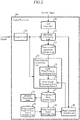
- Fig. 2 is a block diagram showing the signal processor 10 of the laser radar apparatus according to Embodiment 1 of the present invention.
- a control unit 20 outputs a control signal showing the pulse width of a pulse to be emitted, the amplification factor of the pulse, etc., to the optical modulation driver 3, and also outputs a control signal showing the LOS direction of the pulse to the LOS direction changing unit 11.
- the control unit 20 further outputs the control signal showing the LOS direction of the pulse to a spectrum calculating unit 22 and a wind velocity calculating unit 24.
- An A/D converter 21 is an analog to digital converter that converts each electric signal outputted from the optical detector 9 into a digital signal.
- the spectrum calculating unit 22 performs a process of splitting a digital signal converted by the A/D converter 21 according to a time, and performing a Fourier transform on each digital signal split according to the time, i.e., the digital signal in each range bin, and thereby calculating a spectrum signal in each range bin for a LOS direction of interest.
- the spectrum calculating unit 22 also performs an incoherent integration (integration process) of adding spectrum signals for each range bin, thereby improving the signal to noise ratio (SNR) of the spectrum signal in each range bin.
- a spectrum storage unit 23 is implemented using a storage device, such as a RAM or hard disk, and stores the spectrum signals calculated by the spectrum calculating unit 22 for each range bin.
- the wind velocity calculating unit 24 is configured with a LOS wind velocity calculating unit 25 and a wind vector calculating unit 26, and performs a process of, when a spectrum signal calculated by the spectrum calculating unit 22 is one in a range bin having a signal strength equal to or greater than a preset threshold Th 1 (first threshold), calculating a wind velocity in the range bin which is the moving velocity of an aerosol from the spectrum signal calculated by the spectrum calculating unit 22.
- Th 1 first threshold
- the LOS wind velocity calculating unit 25 For each LOS direction of pulse, when a spectrum signal calculated by the spectrum calculating unit 22 is one in a range bin having a signal strength equal to or greater than the preset threshold Th 1 , the LOS wind velocity calculating unit 25 performs a process of calculating a LOS wind velocity in the range bin from the spectrum signal calculated by the spectrum calculating unit 22.
- the wind vector calculating unit 26 From the LOS wind velocities in range bins that are calculated for each LOS direction by the LOS wind velocity calculating unit 25 and are having a signal strength equal to or greater than the threshold Th 1 , the wind vector calculating unit 26 performs a process of calculating a wind velocity for a range bin of interest.
- a data storage unit 27 is implemented as a storage device, such as a RAM or a hard disk, and stores the wind velocities calculated by the wind vector calculating unit 26.
- a wind velocity model storage unit 28 is implemented as a storage device, such as a RAM or a hard disk, and stores, as wind velocity models showing a relationship between altitudes (range bins) and wind velocities in the atmosphere, for example, a "downburst model", a "power-law model” and a “wind shear model.”
- a relationship between altitudes and wind velocities changes greatly dependently on seasons (times) and areas, and the parameters of each wind velocity model change greatly dependently on times and areas.
- a wind velocity model selecting unit 29 performs a process of calculating a degree of matching to each of the plural wind velocity models stored in the wind velocity model storage unit 28 from the wind velocity in each of the range bins stored in the data storage unit 27, comparing the degrees of matching to the plural wind velocity models with one another, and selecting a wind velocity model corresponding to the wind velocities in the range bins on the basis of a result of the comparison among the degrees of matching.
- the wind velocity model selecting unit 29 performs a process of selecting, as the wind velocity model corresponding to the wind velocities in the range bins, the wind velocity model with the highest degree of matching from the plural wind velocity models stored in the wind velocity model storage unit 28.
- a wind velocity searching unit 30 performs a process of determining a search center of a search scope for a Doppler frequency corresponding to the wind velocity in the range bin by using the wind velocity model selected by the wind velocity model selecting unit 29, and searching for a wind velocity in the range bin from the spectrum signal within the search scope whose search center is determined thereby.
- a display processing unit 31 performs a process of displaying the wind velocity in each of the range bins stored in the data storage unit 27.
- each of the following components is implemented as hardware for exclusive use.
- the hardware for exclusive use for example, a semiconductor integrated circuit equipped with a CPU, a one chip microcomputer or the like can be considered.
- Fig. 3 is a hardware block diagram in the case in which the signal processor 10 is implemented as a computer.
- the spectrum storage unit 23, the data storage unit 27 and the wind velocity model storage unit 28 can be configured on a memory 41 of the computer, a program in which the processes performed by the control unit 20, the spectrum calculating unit 22, the wind velocity calculating unit 24, the wind velocity model selecting unit 29, the wind velocity searching unit 30 and the display processing unit 31 are described can be stored in the memory 41, and a processor 42 of the computer can be made to execute the program stored in the memory 41.
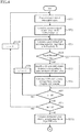
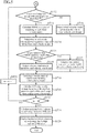
- Figs. 4 and 5 are flow charts showing a wind velocity observation method which corresponds to the processing performed by the signal processor 10 of the laser radar apparatus according to Embodiment 1 of the present invention.
- Fig. 6 is an explanatory drawing showing a spectrum signal in a high SNR area and a spectrum signal in a low SNR area.
- the peak of noise may be higher than the peak of the spectrum signal. Therefore, in the low SNR area, the peak of noise may be detected erroneously as the peak of the spectrum signal, and an incorrect wind velocity may be calculated.
- Fig. 7 is an explanatory drawing showing an example of determining a part of the frequencies as the peak search scope (search scope), and searching for the peak of the spectrum signal within the peak search scope.
- Embodiment 1 the laser radar apparatus that limits the search scope for the spectral peak will be explained.
- a position close to the position of the peak of the spectrum signal is determined as the search center of the peak search scope, so that the search scope can be narrowed.
- the control unit 20 of the signal processor 10 outputs a control signal showing a pulse width of a pulse to be emitted, an amplification factor of the pulse, etc., to the optical modulation driver 3, and also outputs a control signal showing a LOS direction of a pulse to the LOS direction changing unit 11.
- the control unit 20 further outputs the control signal showing the LOS direction of the pulse to the spectrum calculating unit 22 and the wind velocity calculating unit 24.
- variable m showing the LOS direction is initially set to 1, and is incremented one by one until the variable m reaches M.
- the optical oscillator 1 generates laser light.
- the optical coupler 2 splits the laser light generated by the optical oscillator 1 into transmission light and local light, and outputs the transmission light to the optical modulator 4 and also outputs the local light to the receiving coupler 8.
- the optical modulation driver 3 controls the optical modulator 4 to perform pulse modulation so that a pulse with a pulse width shown by the control signal is provided, and also sets the amplification factor of the optical amplifier 5 to the one shown by the control signal.
- the optical modulator 4 outputs a pulse to the optical amplifier 5 by performing pulse modulation on the transmission light outputted from the optical coupler 2 under the control of the optical modulation driver 3.
- the optical amplifier 5 When receiving the pulse from the optical modulator 4, the optical amplifier 5 amplifies the pulse with the amplification factor set by the optical modulation driver 3, and outputs the pulse amplified thereby to the circulator 6.
- the circulator 6 When receiving the pulse from the optical amplifier 5, the circulator 6 outputs the pulse to the Tx/Rx optical system 7.
- the LOS direction changing unit 11 controls the Tx/Rx optical system 7 in such a way that the pulse is emitted in the LOS direction m shown by the control signal.
- the Tx/Rx optical system 7 After emitting the pulse outputted from the circulator 6 in the LOS direction m, the Tx/Rx optical system 7 receives reflected light of the pulse which is reflected from an aerosol, which is an observation object, and returned back.
- the LOS direction changing unit 11 changes the LOS direction m of the pulse in a mechanical manner by controlling a driving device that adjusts the direction of the Tx/Rx optical system 7, though plural Tx/Rx optical systems 7 having different LOS directions can be provided, an optical switch can be disposed between the plural Tx/Rx optical systems 7 and the circulator 6, and, when receiving a pulse from the circulator 6, the optical switch can output the pulse to a Tx/Rx optical system 7 corresponding to the LOS direction m shown by the control signal outputted from the control unit 20, among the plural Tx/Rx optical systems 7, and can output reflected light of the pulse which is received by the Tx/Rx optical system 7 corresponding to the LOS direction m to the circulator 6.
- Embodiment 1 is not limited to the example of changing the LOS direction m of a pulse in a mechanical manner, and the LOS direction m of a pulse can be changed optically by using, for example, a wedge scanner.
- Embodiment 1 an example of changing the LOS direction m of a pulse in order to calculate a wind velocity which is the moving velocity of an aerosol from plural LOS wind velocities will be explained, it is not necessary to change the LOS direction of a pulse and therefore the LOS direction changing unit 11 is unnecessary when a wind velocity in a single LOS direction is defined as the moving velocity of an aerosol.
- the circulator 6 outputs, as received light, reflected light of a pulse which is received by the Tx/Rx optical system 7 to the receiving coupler 8.
- the receiving coupler 8 combines the local light outputted from the optical coupler 2 and the received light outputted from the circulator 6, thereby outputting combined light having a frequency which is the addition of the frequency of the local light and the frequency of the received light to the optical detector 9.
- the optical detector 9 converts the combined light into an electric signal and outputs the electric signal to the signal processor 10.
- the signal processor 10 When receiving the electric signal from the optical detector 9, the signal processor 10 analyzes the electric signal, thereby calculating a wind velocity V W which is the moving velocity of an aerosol, and a wind direction Dir.
- the A/D converter 21 of the signal processor 10 converts the electric signal into a digital signal (step ST1 of Fig. 4 ).
- the spectrum calculating unit 22 calculates a spectrum signal in each of range bins in the LOS direction m whenever the LOS direction m is changed by the LOS direction changing unit 11 (step ST2).
- the spectrum calculating unit 22 divides the digital signal into digital signals with respect to time, and performs a Fourier transform on each of the digital signals divided with respect to time, i.e., the digital signal in each of the range bins, thereby calculating a spectrum signal in each of the range bins in the LOS direction m.
- the spectrum signal in each range bin n in the LOS direction m which is calculated by the spectrum calculating unit 22, is stored in the spectrum storage unit 23.
- the spectrum calculating unit 22 may perform an incoherent integrating process of adding spectrum signals in each of the range bins and a spectrum signal after the incoherent integration may be stored in the spectrum storage unit 23.
- the peak of the spectrum signal is not detected erroneously and therefore a wind velocity can be calculated correctly
- the peak of noise may be detected erroneously as the peak of the spectrum signal and an incorrect wind velocity may be calculated.
- the threshold Th 1 for determining whether the spectrum signal calculated by the spectrum calculating unit 22 belongs either the high SNR area or the low SNR area is set in advance.
- the threshold Th 1 is used for classifying the spectrum signal calculated by the spectrum calculating unit 22 into either the high SNR area or the low SNR area. For example, by performing simulation calculations using a computer, a value which provides a normal detection probability of more than 99.9999% can be set. For example, the threshold Th 1 is set to 0.5 dB.
- the LOS wind velocity calculating unit 25 of the wind velocity calculating unit 24 reads the spectrum signal in each of the range bins in the LOS direction m, which is stored in the spectrum storage unit 23, and compares the signal strength of the spectrum signal in the range bin n with the threshold Th 1 (step ST3).
- the LOS wind velocity calculating unit 25 searches for a peak value of the spectrum signal and specifies, as a Doppler shift amount f d , the frequency at which the spectrum signal has the peak value, because the spectrum signal belongs to the high SNR area and therefore the possibility that the peak of the spectrum signal is detected erroneously is low (step ST5) .
- the LOS wind velocity calculating unit 25 calculates a LOS wind velocity v d in the range bin n from the Doppler shift amount f d and the wavelength ⁇ of the pulse, as shown in the following expression (1) (step ST6).
- v d f d ⁇
- steps ST3 to ST6 are repeatedly performed on all the range bins in the LOS direction m (steps ST7 and ST8) .
- steps ST1 to ST8 are repeatedly performed until the LOS wind velocity v d in each of the range bins in the high SNR area in all LOS directions is calculated (steps ST9 and ST10).
- the LOS wind velocity v d calculated by the LOS wind velocity calculating unit 25 is one in a range bin in the high SNR area, while a LOS wind velocity in a range bin in the low SNR area in which the signal strength of the spectrum signal is less than the threshold Th 1 is not calculated.
- a LOS wind velocity in a range bin in the low SNR area is calculated by the wind velocity searching unit 30.
- the LOS wind velocity calculating unit 25 searches for the peak value of the spectrum signal and specifies, as the Doppler shift amount f d , the frequency at which the spectrum signal has the peak value is shown, this is only an example.
- the LOS wind velocity calculating unit can perform a centroid calculating process of calculating the centroid position of the spectrum signal, and specify, as a Doppler shift amount f d , the frequency at which the spectrum signal has the centroid position.
- the peak search scope within which the LOS wind velocity calculating unit 25 searches for the peak value of the spectrum signal is the whole frequency range. This is because if, instead of defining the whole frequency range as the peak search scope within which the LOS wind velocity calculating unit searches for the peak value of the spectrum signal, the peak search scope is limited to, for example, a range that depends on a wind velocity model stored in the wind velocity model storage unit 28, a wind velocity distribution acquired from the LOS wind velocities v d in all the range bins depends on the wind velocity model, and therefore a wind velocity distribution occurring now cannot be acquired.
- the wind vector calculating unit 26 of the wind velocity calculating unit 24 performs a vector operation on plural LOS wind velocities v d whose number is M at the maximum, for each identical range bin, thereby calculating a horizontal wind velocity V W as the wind velocity in the range bin and also calculating a wind direction Dir in the range bin (step ST11) .
- a vector operation is performed on the M LOS wind velocities v d .
- a vector operation is performed on the (M-2) LOS wind velocities v d .
- ⁇ denotes azimuth angle measured with respect to the north
- ⁇ denotes zenith angle
- U denotes east-west direction wind velocity
- V denotes north-south direction wind velocity
- W denotes vertical direction wind velocity
- v d 1 U sin ⁇ 1 sin ⁇ 1 + V cos ⁇ 1 sin ⁇ 1 + W cos ⁇ 1
- v d 2 U sin ⁇ 2 sin ⁇ 2 + V cos ⁇ 2 sin ⁇ 2 + W cos ⁇ 2
- v d 3 U sin ⁇ 3 sin ⁇ 3 + V cos ⁇ 3 sin ⁇ 3 + W cos ⁇ 3
- U, V and W are expressed by the following expression (7) by solving expression (6) for U, V and W.
- U 1 A A 22 A 33 ⁇ A 23 A 32 v 1 + A 13 A 32 ⁇ A 12 A 33 v 2 + A 12 A 23 ⁇ A 13 A 22 v 3
- V 1 A A 23 A 31 ⁇ A 21 A 33 v 1 + A 11 A 33 ⁇ A 13 A 31 v 2 + A 13 A 21 ⁇ A 11 A 23 v 3
- W 1 A A 21 A 32 ⁇ A 22 A 31 v 1 + A 12 A 11 ⁇ A 11 A 32 v 2 + A 11 A 22 ⁇ A 12 A 21 v 3
- the wind vector calculating unit 26 calculates the horizontal wind velocity V W and the wind direction Dir in the range bin in the high SNR area by using the east-west direction wind velocity U and the north-south direction wind velocity V, as shown in the following expressions (8) and (9).
- ⁇ denotes an angle of elevation (an angle which the front direction of the laser radar apparatus forms with respect to the ground surface).
- the wind vector calculating unit 26 calculates the horizontal wind velocity V W by using the east-west direction wind velocity U and the north-south direction wind velocity V is shown, this is only an example, and the wind vector calculating unit can alternatively calculate the horizontal wind velocity V W by using another method.
- the horizontal wind velocity V W and the wind direction Dir in the range bin in the high SNR area which are calculated by the wind vector calculating unit 26 are stored in the data storage unit 27.
- the wind velocity model storage unit 28 stores, as the wind velocity models each showing a relationship between altitudes and wind velocities in the atmosphere, for example, the "downburst model", the "power-law model” and the “wind shear model.”
- Fig. 8 is an explanatory drawing showing the downburst model, the power-law model and the wind shear model.
- the wind velocity model selecting unit 29 initializes the variable m showing the LOS direction to 1, and, when the number of range bins in the high SNR area in the LOS direction m, i.e., the number of range bins for each of which the horizontal wind velocity V W and the wind direction Dir are calculated by the wind vector calculating unit 26 is equal to or larger than Th 3 (third threshold) (YES in step ST12), calculates the degree of matching to each of the plural wind velocity models stored in the wind velocity model storage unit 28 from the horizontal wind velocities V W in the range bins in the high SNR area stored in the data storage unit 27 (step ST13).
- the threshold Th 3 is preset by the user, and, for example, it is contemplated that in consideration of the resolution of altitudes (distances), the threshold Th 3 is set to a value adequate to detect variations in the wind velocity. For example, the threshold Th 3 is set to 10.
- Embodiment 1 an example in which, as the degree of matching to each of the wind velocity models, an RMSE shown in the following expression (10) is calculated will be explained.
- V W (z) denotes the horizontal wind velocity at a time when the range bin (altitude) calculated by the wind vector calculating unit 26 is z
- fm(z) denotes the horizontal wind velocity which is acquired from a wind velocity model at a time when the range bin (altitude) is z.
- N denotes the number of range bins in the LOS direction m for each of which the horizontal wind velocity V W and the wind direction Dir are calculated by the wind vector calculating unit 26.
- the horizontal wind velocity fm(z) acquired from a wind velocity model depend on the wind velocity model, as a matter of course.
- the horizontal wind velocity is expressed by the following expression (11).
- fm z u ⁇ z 0 z z 0 p
- u denotes the wind velocity at a reference altitude z 0 . It is preferable to use, for example, the wind velocity (horizontal wind velocity V W (z) calculated by the wind vector calculating unit 26) in the range bin with the lowest altitude among the range bins in the high SNR area.
- a parameter (variable) of each wind velocity model is denoted by p.
- the wind velocity model selecting unit 29 calculates the RMSE given by expression (10) while changing the parameter p of the wind velocity model, and specifies the minimum value of the RMSE.
- the minimum value of the RMSE is defined as a representative value of the RMSE.
- the wind velocity model selecting unit 29 After specifying the representative values of the RMSE for all the wind velocity models stored in the wind velocity model storage unit 28, the wind velocity model selecting unit 29 compares the representative values of the RMSE of all the wind velocity models with one another, and selects a wind velocity model with the smallest representative value of the RMSE from among the plural wind velocity models stored in the wind velocity model storage unit 28 (step ST14).
- the wind velocity model with the smallest representative value of the RMSE is the one with the highest degree of matching among the plural wind velocity models.
- the wind velocity model selecting unit 29 After selecting the wind velocity model with the smallest representative value of the RMSE, the wind velocity model selecting unit 29 compares the representative value of the RMSE with a preset threshold Th 2 , and, when the representative value of the RMSE is equal to or smaller than the threshold Th 2 (YES in step ST15), outputs the selected wind velocity model to the wind velocity searching unit 30 (step ST16) .
- the fact that the representative value of the RMSE is equal to or smaller than the threshold Th 2 means that the degree of matching to the wind velocity model is equal to or greater than a second threshold, and the threshold Th 2 corresponds to the second threshold.
- the wind velocity model selecting unit 29 When the representative value of the RMSE is larger than the threshold Th 2 (No in step ST15), the wind velocity model selecting unit 29 generates a new wind velocity model and outputs the wind velocity model to the wind velocity searching unit 30 because there is a possibility that there occurs a natural phenomenon which is not represented by any of the plural wind velocity models stored in the wind velocity model storage unit 28, i.e., the wind velocity models set as standard (step ST17) .
- a new wind velocity model is generated. More specifically, a wind velocity model expressed by an approximate polynomial is generated using the horizontal wind velocities V W in the range bins in the high SNR area.
- the wind velocity model selecting unit 29 outputs a wind velocity model which the wind velocity model selecting unit selected in the past to the wind velocity searching unit 30 (step ST18).
- the wind velocity model selected in the past for example, the wind velocity model which the wind velocity model selecting unit selected the last time is generated to the wind velocity searching unit 30.
- the wind velocity searching unit 30 determines a search center IF of the search scope for a Doppler frequency corresponding to a wind velocity in the range bin in the low SNR area by using the wind velocity model outputted from the wind velocity model selecting unit 29 (step ST19).
- the wind velocity searching unit 30 acquires the horizontal wind velocity fm(z) and the wind direction Dir (z) which correspond to z from the wind velocity model outputted from the wind velocity model selecting unit 29 and substitutes the horizontal wind velocity fm (z) and the wind direction Dir (z) into the following expression (12), thereby calculating the search center IF of the preset search scope.
- IF fm z ⁇ cos Dir z ⁇ ⁇ ⁇ sin ⁇ ⁇ ⁇
- Fig. 9 is an explanatory drawing showing the search center IF determined by the wind velocity searching unit 30.
- Fig. 9A shows an example in which the search scope is determined using the method disclosed in Patent Literature 3. More specifically, an example in which the search scope is determined using a standard deviation of wind velocities is shown.
- the search center IF of the search scope is not determined, it is necessary to determine a certain large search scope even if the search scope is limited. Therefore, the probability that the peak of noise is detected erroneously as the peak of a spectrum signal is increased.
- Fig. 9B shows an example of the search center IF determined by the wind velocity searching unit 30, and the center of the search scope matches the search center IF in this example.
- search scope shown in Fig. 9B has a preset fixed size.
- Embodiment 1 because the search center IF of the search scope is optimized, it is possible to detect the peak of a spectrum signal without extending the search scope.
- the wind velocity searching unit 30 After calculating the search center IF of the search scope, the wind velocity searching unit 30 searches for the wind velocity in the range bin in the low SNR area from the spectrum signal within the search scope whose search center IF is determined (step ST20).
- the wind velocity searching unit 30 searches for the peak value of the spectrum signal within the search scope whose search center IF is determined, and specifies, as the Doppler shift amount f d , the frequency at which the spectrum signal has the peak value.
- the wind velocity searching unit 30 calculates the LOS wind velocity v d in the range bin in the low SNR area from the Doppler shift amount f d and the wavelength ⁇ of the pulse, as shown in the above-mentioned expression (1), and outputs the LOS wind velocity v d to the wind vector calculating unit 26 of the wind velocity calculating unit 24.
- steps ST12 to ST20 are repeatedly performed until the LOS wind velocity v d in each of the range bins in the low SNR area in all LOS directions is calculated (steps ST21 and ST22).
- the wind vector calculating unit 2 When receiving the LOS wind velocities v d in the range bins in the low SNR area from the wind velocity searching unit 30, the wind vector calculating unit 2 performs a vector operation on plural LOS wind velocities v d whose number is M at the maximum, for each identical range bin, thereby calculating a horizontal wind velocity V W as the wind velocity in the range bin and also calculating a wind direction Dir, like in the case of receiving the LOS wind velocities v d in the range bins in the high SNR area from the LOS wind velocity calculating unit 25 (step ST23).
- a vector operation is performed on the M LOS wind velocities v d .
- a vector operation is performed on the (M-1) LOS wind velocities v d .
- the horizontal wind velocities V W and the wind directions Dir in the range bins in the low SNR area which are calculated by the wind vector calculating unit 26 are stored in the data storage unit 27.
- the display processing unit 31 reads the horizontal wind velocity V W and the wind direction Dir in each of the range bins in the high SNR area and those in the low SNR area which are stored in the data storage unit 27, and displays the horizontal wind velocity V W and the wind direction Dir in each of the range bins in the high SNR area and those in the low SNR area on a display (step ST24).
- the wind velocity searching unit 30 is configured so as to, when a spectrum signal calculated by the spectrum calculating unit 22 is one in a range bin having a signal strength less than the threshold Th 1 , determine the search center IF of the search scope for a Doppler frequency corresponding to a wind velocity in the range bin by using a wind velocity model selected by the wind velocity model selecting unit 29, and search for the wind velocity in the range bin from the spectrum signal within the search scope whose search center IF is determined thereby, there is provided an advantage of being able to reduce the probability that the peak of noise is detected erroneously as the peak of the spectrum signal, and calculate the wind velocity with a high degree of accuracy. There is provided another advantage of being able to lengthen the measurable distance of wind velocities.
- the wind velocity model selecting unit 29 outputs a wind velocity model selected in the past to the wind velocity searching unit 30 because it is difficult to generate a new wind velocity model with a high degree of accuracy is shown.
- the wind vector calculating unit 26 can calculate a horizontal wind velocity V W and a wind direction Dir in each of the range bins in the high SNR area so as not to output any wind velocity model selected in the past to the wind velocity searching unit 30.
- Fig. 10 is a block diagram showing a signal processor 10 of a laser radar apparatus according to Embodiment 2 of the present invention.
- Fig. 10 because the same reference numerals as those shown in Fig. 2 denote the same components or like components, the explanation of the components will be omitted hereafter.
- a control unit 50 outputs a control signal showing the pulse width of a pulse to be emitted, the amplification factor of the pulse, etc. to an optical modulation driver 3, like the control unit 20 shown in Fig. 2 , and also outputs a control signal showing the LOS direction of the pulse to a LOS direction changing unit 11.
- the control unit 50 further outputs the control signal showing the LOS direction of the pulse to a spectrum calculating unit 22 and a wind velocity calculating unit 24.
- the control unit 50 When the number of range bins in a high SNR area in the LOS direction m for each of which a horizontal wind velocity V W and a wind direction Dir are calculated by a wind vector calculating unit 26 is smaller than a threshold Th 3 , the control unit 50 outputs a control signal for instructing enlargement of the pulse width of a pulse to be emitted from a Tx/Rx optical system 7 to the optical modulation driver 3, unlike the control unit 20 shown in Fig. 2 . Instead, the control unit 50 outputs a control signal that instructs an increase in the number of times of the incoherent integrating process, which adds spectrum signals in each of the range bins, to the spectrum calculating unit 22.
- each of the following components is implemented as hardware for exclusive use.
- the hardware for exclusive use for example, a semiconductor integrated circuit equipped with a CPU, a one chip microcomputer or the like can be considered.
- the signal processor 10 may be implemented as a computer.
- a spectrum storage unit 23, a data storage unit 27 and a wind velocity model storage unit 28 can be configured on a memory 41 shown in Fig. 3 of the computer, a program in which the processes performed by the control unit 50, the spectrum calculating unit 22, the wind velocity calculating unit 24, the wind velocity model selecting unit 29, the wind velocity searching unit 30 and the display processing unit 31 are described can be stored in the memory 41, and a processor 42 of the computer can be made to execute the program stored in the memory 41.
- the wind velocity model selecting unit 29 outputs a wind velocity model selected in the past to the wind velocity searching unit 30.
- the wind velocity searching unit 30 calculates a LOS wind velocity v d in a range bin in a low SNR area by using a wind velocity model selected in the past, there is a possibility that the calculation accuracy of the LOS wind velocity v d degrades because the wind velocity model selected in the past does not necessarily represent a current wind velocity distribution.
- the wind velocity model selecting unit 29 can generate a new wind velocity model with a high degree of accuracy by using the horizontal wind velocities V W in the range bins in the high SNR area. Instead, the wind velocity model selecting unit 29 can select a wind velocity model with the highest degree of matching from plural wind velocity models stored in the wind velocity model storage unit 28.
- Embodiment 2 when the number of range bins in the high SNR area in the LOS direction m for each of which the horizontal wind velocity V W and the wind direction Dir are calculated by the wind vector calculating unit 26 is smaller than the threshold Th 3 , the control unit 50 controls the optical modulation driver 3 and the spectrum calculating unit 22 in such a way that the number of range bins in the high SNR area is increased.
- control unit 50 outputs a control signal for instructing enlargement of the pulse width of a pulse to be emitted from the Tx/Rx optical system 7 to the optical modulation driver 3.
- the optical modulation driver 3 controls the pulse modulation by the optical modulator 4 in such a way that the pulse width is enlarged.
- the pulse width of the pulse emitted from the Tx/Rx optical system 7 is enlarged, the SNR of reflected light becomes high.
- an altitude (distance) up to which wind measurements can be performed can be increased by setting the focus position of the Tx/Rx optical system 7 to be a distant position.
- the control unit 50 can change the amplification factor of an optical amplifier 5 simultaneously.
- control unit 50 can output a control signal for instructing an increase in the number of times that the incoherent integrating process of adding spectrum signals in each of the range bins is to be performed to the spectrum calculating unit 22.
- the spectrum calculating unit 22 When receiving the control signal for instructing an increase in the number of times that the incoherent integrating process is to be performed, the spectrum calculating unit 22 increases the number of times that the incoherent integrating process of adding spectrum signals in each of the range bins is to be performed. Because the SNR becomes high even by increasing the number of times that the incoherent integrating process is to be performed, the number of range bins in the high SNR area can be increased.
- the number of times that the incoherent integrating process is to be performed cannot be increased to an unlimited extent, and an upper limit on the number of times that the incoherent integrating process is to be performed is set dependently on a time period during which the precondition that winds are uniform does not break, the number of times that the incoherent integrating process is to be performed can be increased within a range that does not exceed the upper limit.
- the signal processor 10 performs a process of calculating the horizontal wind velocity V W , like that according to above-mentioned Embodiment 1.
- the wind velocity model selecting unit 29 can generate a new wind velocity model with a high degree of accuracy by using the horizontal wind velocities V W in the range bins in the high SNR area and output the new wind velocity model to the wind velocity searching unit 30, without outputting a wind velocity model selected in the past to the wind velocity searching unit 30.
- the wind velocity model selecting unit 29 can select a wind velocity model with the highest degree of matching from the plural wind velocity models stored in the wind velocity model storage unit 28, and output the wind velocity model to the wind velocity searching unit 30.
- control unit 50 is configured so as to, when the number of range bins in the high SNR area in the LOS direction m for each of which the horizontal wind velocity V W and the wind direction Dir are calculated by the wind vector calculating unit 26 is smaller than the threshold Th 3 , output the control signal for instructing enlargement of the pulse width of a pulse to be emitted from the Tx/Rx optical system 7 to the optical modulation driver 3, or output the control signal for instructing an increase in the number of times that the incoherent integrating process of adding spectrum signals in each of the range bins is to be performed to the spectrum calculating unit 22, there is provided an advantage of being able to increase the number of range bins in the high SNR area in a situation in which the number of range bins in the high SNR area is small, thereby improving the calculation accuracy of the horizontal wind velocity V W .
- the laser radar apparatus according to the present invention is suitable for use as a laser radar apparatus that, when observing a wind velocity in the atmosphere, needs to reduce the probability that the peak of noise is detected erroneously as the peak of a spectrum signal.
Landscapes
- Engineering & Computer Science (AREA)
- Physics & Mathematics (AREA)
- General Physics & Mathematics (AREA)
- Electromagnetism (AREA)
- Computer Networks & Wireless Communication (AREA)
- Radar, Positioning & Navigation (AREA)
- Remote Sensing (AREA)
- Multimedia (AREA)
- Aviation & Aerospace Engineering (AREA)
- Optical Radar Systems And Details Thereof (AREA)
Claims (6)
- Laserradarvorrichtung, umfassend:ein optisches Übertragungs- und Empfangssystem (7) zum Aussenden eines Impulses in eine Atmosphäre und zum Empfangen von reflektiertem Licht des Impulses, der von einem Beobachtungsobjekt reflektiert und zurückgegeben wird;eine Spektrum-Berechnungseinheit zum Berechnen eines Spektrumsignals (22) in Entfernungszellen aus dem reflektierten Licht, das von dem optischen Übertragungs- und Empfangssystem empfangen wird;eine Windgeschwindigkeitsberechnungseinheit (24), um, wenn eine Signalstärke in einer Entfernungszelle, für die ein von der Spektrum-Berechnungseinheit berechnetes Spektrumssignal gleich oder größer als ein erster Schwellenwert ist, eine Windgeschwindigkeit in der Entfernungszelle, die eine Geschwindigkeit des Beobachtungsobjekts ist, aus dem Spektrumssignal zu berechnen;eine Windgeschwindigkeitsmodellauswahleinheit (29) zum Auswählen eines Windgeschwindigkeitsmodells, das den Windgeschwindigkeiten in den Entfernungszellen entspricht, die von der Windgeschwindigkeitsberechnungseinheit aus einer Vielzahl von Windgeschwindigkeitsmodellen berechnet werden, die jeweils eine Beziehung zwischen Entfernungszellen und Windgeschwindigkeiten in der Atmosphäre aufzeigen; undeine Windgeschwindigkeitssucheinheit (30), um, wenn eine Signalstärke in einer Entfernungszelle, für die ein von der Spektrum-Berechnungseinheit berechnetes Spektrumssignal kleiner als der erste Schwellenwert ist, ein Suchzentrum eines Suchbereichs für eine Dopplerfrequenz zu bestimmen, die einer Windgeschwindigkeit in der Entfernungszelle entspricht, unter Verwendung des von der Windgeschwindigkeitsmodellauswahleinheit ausgewählten Windgeschwindigkeitsmodells, und um eine Windgeschwindigkeit in der Entfernungszelle aus dem Spektrumssignal innerhalb des Suchbereichs zu suchen, dessen Suchzentrum bestimmt wird.
- Laserradarvorrichtung nach Anspruch 1, ferner umfassend:eine Sichtlinienrichtungsänderungseinheit (11) zum Ändern einer Sichtlinie, die eine Richtung eines Impulses ist, der von dem optischen Übertragungs- und Empfangssystem ausgesendet werden soll, wobeidie Spektrum-Berechnungseinheit, wann immer die Sichtlinie durch die Sichtlinienrichtungsänderungseinheit geändert wird, ein Spektrumssignal in Entfernungszellen für jede Sichtlinie aus dem reflektierten Licht berechnet, das von dem optischen Übertragungs- und Empfangssystem empfangen wird, unddie Windgeschwindigkeitsberechnungseinheit, wann immer die Sichtlinie durch die Sichtlinienrichtungsänderungseinheit geändert wird, wenn eine Signalstärke in einer Entfernungszelle, für die ein von der Spektrum-Berechnungseinheit berechnetes Spektrumssignal gleich oder größer als der erste Schwellenwert ist, eine Sichtlinienwindgeschwindigkeit in der Entfernungszelle aus dem von der Spektrum-Berechnungseinheit berechneten Spektrumssignal berechnet, und eine Windgeschwindigkeit in der Entfernungszelle aus einer Vielzahl von Sichtlinienwindgeschwindigkeiten in den Entfernungszellen von Interesse in jeder Sichtlinie berechnet.
- Laserradarvorrichtung nach Anspruch 1, wobei die Windgeschwindigkeitsmodellauswahleinheit aus Windgeschwindigkeiten in jeder Entfernungszelle, die von der Windgeschwindigkeitsberechnungseinheit berechnet werden, Übereinstimmungsgrade zu den mehreren Windgeschwindigkeitsmodellen berechnet, die Übereinstimmungssgrade zu den mehreren Windgeschwindigkeitsmodellen miteinander vergleicht und ein Windgeschwindigkeitsmodell entsprechend den Windgeschwindigkeiten in jeder Entfernungszelle auf Grundlage eines Ergebnisses des Vergleichs der Übereinstimmungsgrade auswählt.
- Laserradarvorrichtung nach Anspruch 3, wobei, wenn es keinen Übereinstimmungsgrad gibt, der gleich oder größer als ein zweiter Schwellenwert in den Übereinstimmungsgraden zu den mehreren Windgeschwindigkeitsmodellen ist, die Windgeschwindigkeitsmodellauswahleinheit unter Verwendung von Windgeschwindigkeiten in Entfernungszellen, die von der Windgeschwindigkeitsberechnungseinheit berechnet werden, ein neues Windgeschwindigkeitsmodell erzeugt, und, wenn eine Signalstärke in einer Entfernungszelle, für die ein von der Spektrum-Berechnungseinheit berechnetes Spektrumssignal kleiner als der erste Schwellenwert ist, die Windgeschwindigkeitssucheinheit unter Verwendung des von der Windgeschwindigkeitsmodellauswahleinheit erzeugten neuen Windgeschwindigkeitsmodells ein Suchzentrum eines Suchbereichs für eine Dopplerfrequenz bestimmt, die einer Windgeschwindigkeit in der Entfernungszelle entspricht, und aus dem Spektrumssignal innerhalb des Suchbereichs, dessen Suchzentrum bestimmt wird, nach einer Windgeschwindigkeit in der Entfernungszelle sucht.
- Laserradarvorrichtung nach Anspruch 3, ferner umfassend:
eine Steuereinheit (20) zum Ausgeben, wenn die Anzahl der Entfernungszellen, für die eine Windgeschwindigkeit durch die Windgeschwindigkeitsberechnungseinheit berechnet wird, kleiner als ein dritter Schwellenwert ist, entweder einer Anweisung zum Vergrößern einer Impulsbreite eines Impulses, der von dem optischen Übertragungs- und Empfangssystem ausgesendet werden soll, oder einer Anweisung zum Erhöhen der Anzahl der Male, die ein Integrationsprozess an von der Spektrum-Berechnungseinheit berechneten Spektrumssignalen durchzuführen hat, um ein Signal-Rausch-Verhältnis des Spektrumssignals zu verbessern. - Windgeschwindigkeit-Beobachtungsverfahren, umfassend:durch ein optisches Übertragungs- und Empfangssystem (7), Aussenden eines Impulses in eine Atmosphäre und Empfangen von reflektiertem Licht des Impulses, der von einem Beobachtungsobjekt reflektiert und zurückgegeben wird;durch eine Spektrum-Berechnungseinheit (22), Berechnen eines Spektrumssignals in Entfernungszellen aus dem reflektierten Licht, das von dem optischen Übertragungs- und Empfangssystem empfangen wird;durch eine Windgeschwindigkeitsberechnungseinheit (24), wenn eine Signalstärke in einer Entfernungszelle, für die ein von der Spektrum-Berechnungseinheit berechnetes Spektrumssignal gleich oder größer als ein erster Schwellenwert ist, Berechnen einer Windgeschwindigkeit in der Entfernungszelle, die eine Geschwindigkeit des Beobachtungsobjekts ist, aus dem Spektrumssignal;durch eine Windgeschwindigkeitsmodellauswahleinheit (29), Auswählen eines Windgeschwindigkeitsmodells, das den Windgeschwindigkeiten in den Entfernungszellen entspricht, die von der Windgeschwindigkeitsberechnungseinheit aus einer Vielzahl von Windgeschwindigkeitsmodellen berechnet werden, die jeweils eine Beziehung zwischen Entfernungszellen und Windgeschwindigkeiten in der Atmosphäre aufzeigen; unddurch eine Windgeschwindigkeitssucheinheit (30), wenn eine Signalstärke in einer Entfernungszelle, für die ein von der Spektrum-Berechnungseinheit berechnetes Spektrumssignal kleiner als der erste Schwellenwert ist, Bestimmen eines Suchzentrums eines Suchbereichs für eine Dopplerfrequenz, die einer Windgeschwindigkeit in der Entfernungszelle entspricht, unter Verwendung des von der Windgeschwindigkeitsmodellauswahleinheit ausgewählten Windgeschwindigkeitsmodells, und Suchen nach einer Windgeschwindigkeit in der Entfernungszelle aus dem Spektrumssignal in dem Suchbereich, dessen Suchzentrum bestimmt wird.
Applications Claiming Priority (1)
| Application Number | Priority Date | Filing Date | Title |
|---|---|---|---|
| PCT/JP2015/063619 WO2016181493A1 (ja) | 2015-05-12 | 2015-05-12 | レーザレーダ装置及び風速観測方法 |
Publications (3)
| Publication Number | Publication Date |
|---|---|
| EP3296765A1 EP3296765A1 (de) | 2018-03-21 |
| EP3296765A4 EP3296765A4 (de) | 2018-12-26 |
| EP3296765B1 true EP3296765B1 (de) | 2019-11-13 |
Family
ID=57248765
Family Applications (1)
| Application Number | Title | Priority Date | Filing Date |
|---|---|---|---|
| EP15891818.5A Active EP3296765B1 (de) | 2015-05-12 | 2015-05-12 | Laserradarvorrichtung und windgeschwindigkeitsbeobachtungsverfahren |
Country Status (5)
| Country | Link |
|---|---|
| US (1) | US10175346B2 (de) |
| EP (1) | EP3296765B1 (de) |
| JP (1) | JP6257845B2 (de) |
| CN (1) | CN107615094B (de) |
| WO (1) | WO2016181493A1 (de) |
Families Citing this family (18)
| Publication number | Priority date | Publication date | Assignee | Title |
|---|---|---|---|---|
| US10319228B2 (en) | 2017-06-27 | 2019-06-11 | Waymo Llc | Detecting and responding to sirens |
| WO2019087387A1 (ja) * | 2017-11-06 | 2019-05-09 | 三菱電機株式会社 | 周波数推定装置及び無線装置 |
| EP3754378B1 (de) * | 2018-03-20 | 2024-10-30 | Mitsubishi Electric Corporation | Radarsignalverarbeitungsvorrichtung |
| US11933903B2 (en) * | 2018-03-29 | 2024-03-19 | Mitsubishi Electric Corporation | Laser radar device |
| JP7097052B2 (ja) * | 2018-04-04 | 2022-07-07 | 国立研究開発法人宇宙航空研究開発機構 | 飛行機の突風応答軽減システム及び飛行機の突風応答軽減方法 |
| WO2019202676A1 (ja) * | 2018-04-18 | 2019-10-24 | 三菱電機株式会社 | レーザレーダ装置 |
| CN111989593B (zh) * | 2018-04-26 | 2024-05-14 | 三菱电机株式会社 | 激光雷达装置、风力发电装置以及风测量方法 |
| CN111684297A (zh) * | 2019-01-09 | 2020-09-18 | 深圳市大疆创新科技有限公司 | 激光雷达的通信方法、激光雷达及上位设备 |
| CN109916852B (zh) * | 2019-01-31 | 2020-11-03 | 上海禾赛科技股份有限公司 | 一种激光气体遥测仪信号采集方法和系统 |
| CN112630746B (zh) * | 2020-12-01 | 2023-09-15 | 北京遥感设备研究所 | 一种用于远距目标测量的脉冲多普勒激光雷达 |
| CN114687951B (zh) * | 2020-12-28 | 2024-09-20 | 北京金风科创风电设备有限公司 | 风速测量设备、方法、装置、存储介质及风力发电机组 |
| CN113138374B (zh) * | 2021-04-08 | 2023-06-02 | 北京观详光电技术有限公司 | 一种激光雷达风场数据重建方法及系统 |
| DE102021002239A1 (de) * | 2021-04-28 | 2022-11-03 | Leonardo Germany Gmbh | Doppler Lidar zur Erfassung von Wind- und/oder Wirbelsituationen |
| CN114488200B (zh) * | 2022-04-17 | 2022-07-15 | 中国科学技术大学 | 一种提高激光雷达测风精度的功率谱信号处理方法 |
| CN114839647A (zh) * | 2022-07-04 | 2022-08-02 | 青岛镭测创芯科技有限公司 | 一种脉冲相干测风激光雷达系统 |
| CN115408952A (zh) * | 2022-08-11 | 2022-11-29 | 上海电气风电集团股份有限公司 | 风速不确定度的计算方法及其装置及计算机可读存储介质 |
| CN115951328B (zh) * | 2023-03-10 | 2023-05-16 | 中国人民解放军国防科技大学 | 基于概率密度约束的测风激光雷达风速估计方法和装置 |
| WO2025088709A1 (ja) * | 2023-10-25 | 2025-05-01 | 三菱電機株式会社 | 風観測装置、風観測方法及び風観測システム |
Family Cites Families (16)
| Publication number | Priority date | Publication date | Assignee | Title |
|---|---|---|---|---|
| JPH10187016A (ja) | 1996-12-20 | 1998-07-14 | Mitsubishi Electric Corp | 道路トンネル環境シミュレーション装置 |
| JP3626089B2 (ja) | 2000-11-30 | 2005-03-02 | 三菱電機株式会社 | ウィンドプロファイラにおける信号処理装置および信号処理方法 |
| JP3724379B2 (ja) * | 2001-03-14 | 2005-12-07 | 三菱電機株式会社 | ウインドシア検出装置 |
| DE10316762B4 (de) * | 2003-04-10 | 2007-01-25 | Eads Deutschland Gmbh | Verfahren zur Erfassung von Windgeschwindigkeiten mit einem Doppler-Lidar-System, insbesondere an Bord von Flugzeugen, und Doppler-Lidar-System |
| GB0411097D0 (en) | 2004-05-19 | 2004-06-23 | Qinetiq Ltd | Laser radar device and method |
| JP5000082B2 (ja) | 2004-06-14 | 2012-08-15 | 三菱電機株式会社 | 光波レーダ装置 |
| JP4806949B2 (ja) | 2005-03-31 | 2011-11-02 | 三菱電機株式会社 | レーザレーダ装置 |
| CN100543493C (zh) * | 2006-04-18 | 2009-09-23 | 中国科学院安徽光学精密机械研究所 | 基于f-p标准具的多普勒测风激光雷达的结构及其探测方法 |
| JP5197023B2 (ja) * | 2008-01-09 | 2013-05-15 | 三菱電機株式会社 | レーザレーダ装置 |
| JP5511196B2 (ja) | 2009-02-19 | 2014-06-04 | 三菱電機株式会社 | 後方乱気流検出装置 |
| JP5376440B2 (ja) * | 2009-03-30 | 2013-12-25 | 独立行政法人 宇宙航空研究開発機構 | 光学式遠隔気流計測装置 |
| US8085182B2 (en) | 2009-03-31 | 2011-12-27 | Honeywell International Inc. | Systems and methods for collecting weather information using an airborne aircraft |
| DE102009030886A1 (de) * | 2009-06-29 | 2010-12-30 | Robert Bosch Gmbh | Windenergieanlage mit einer Vielzahl von Windenergievorrichtungen und Verfahren zur Steuerung der Windenergieanlage |
| CN101710178B (zh) * | 2009-12-04 | 2012-10-10 | 中国海洋大学 | 实时定标高光谱分辨率激光雷达装置 |
| EP2884306B1 (de) * | 2012-08-08 | 2017-09-13 | Mitsubishi Electric Corporation | Radarvorrichtung |
| EP2896972B1 (de) * | 2012-09-14 | 2019-10-30 | Mitsubishi Electric Corporation | Laserradarvorrichtung und verfahren für den nachweis der geschwindigkeit eines gemessenen objekts |
-
2015
- 2015-05-12 JP JP2017517515A patent/JP6257845B2/ja active Active
- 2015-05-12 WO PCT/JP2015/063619 patent/WO2016181493A1/ja not_active Ceased
- 2015-05-12 EP EP15891818.5A patent/EP3296765B1/de active Active
- 2015-05-12 CN CN201580079790.XA patent/CN107615094B/zh active Active
- 2015-05-12 US US15/572,758 patent/US10175346B2/en active Active
Non-Patent Citations (1)
| Title |
|---|
| None * |
Also Published As
| Publication number | Publication date |
|---|---|
| CN107615094A (zh) | 2018-01-19 |
| CN107615094B (zh) | 2018-09-07 |
| US10175346B2 (en) | 2019-01-08 |
| EP3296765A4 (de) | 2018-12-26 |
| EP3296765A1 (de) | 2018-03-21 |
| US20180156893A1 (en) | 2018-06-07 |
| WO2016181493A1 (ja) | 2016-11-17 |
| JP6257845B2 (ja) | 2018-01-10 |
| JPWO2016181493A1 (ja) | 2017-07-20 |
Similar Documents
| Publication | Publication Date | Title |
|---|---|---|
| EP3296765B1 (de) | Laserradarvorrichtung und windgeschwindigkeitsbeobachtungsverfahren | |
| EP2884306B1 (de) | Radarvorrichtung | |
| EP3548926B1 (de) | Verfahren und system zur adaptiven abtastung mit optischen entfernungsmesssystemen | |
| EP3531168B1 (de) | Datenverarbeitungsvorrichtung, laserradarvorrichtung und windmesssystem | |
| US11112502B2 (en) | Laser radar system | |
| US9851444B2 (en) | Laser radar device and method of calculating speed of object to be measured | |
| CN108398677A (zh) | 三坐标连续波一维相扫无人机低空目标检测系统 | |
| US20230140139A1 (en) | Radar Detection Method and Related Apparatus | |
| US20230228862A1 (en) | Radar Detection Method and Related Apparatus | |
| US20230168381A1 (en) | Radar Detection Method and Related Apparatus | |
| EP3418770B1 (de) | Radarsignalverarbeitungsvorrichtung mit synthetischer apertur | |
| US20240103150A1 (en) | Laser radar device | |
| EP3399334A1 (de) | Objektdetektor und sensorvorrichtung | |
| EP3985417B1 (de) | Vorrichtung und verfahren zur beobachtung eines entfernten luftstroms und programm | |
| RU2083996C1 (ru) | Способ селекции надводных целей | |
| RU2584496C1 (ru) | Радиоволновое устройство для тревожной сигнализации с непрерывным излучением частотно-модулированных колебаний | |
| US20240288554A1 (en) | Laser radar device | |
| JP7724997B1 (ja) | 風観測装置、風観測方法及び風観測システム | |
| RU2834733C1 (ru) | Способ формирования фиксированной спектральной зоны, свободной от помех от подстилающей поверхности в бортовых импульсно-доплеровских радиолокаторах |
Legal Events
| Date | Code | Title | Description |
|---|---|---|---|
| STAA | Information on the status of an ep patent application or granted ep patent |
Free format text: STATUS: THE INTERNATIONAL PUBLICATION HAS BEEN MADE |
|
| PUAI | Public reference made under article 153(3) epc to a published international application that has entered the european phase |
Free format text: ORIGINAL CODE: 0009012 |
|
| STAA | Information on the status of an ep patent application or granted ep patent |
Free format text: STATUS: REQUEST FOR EXAMINATION WAS MADE |
|
| 17P | Request for examination filed |
Effective date: 20171114 |
|
| AK | Designated contracting states |
Kind code of ref document: A1 Designated state(s): AL AT BE BG CH CY CZ DE DK EE ES FI FR GB GR HR HU IE IS IT LI LT LU LV MC MK MT NL NO PL PT RO RS SE SI SK SM TR |
|
| AX | Request for extension of the european patent |
Extension state: BA ME |
|
| DAV | Request for validation of the european patent (deleted) | ||
| DAX | Request for extension of the european patent (deleted) | ||
| A4 | Supplementary search report drawn up and despatched |
Effective date: 20181123 |
|
| RIC1 | Information provided on ipc code assigned before grant |
Ipc: G01S 7/48 20060101ALI20181119BHEP Ipc: G01P 5/26 20060101ALI20181119BHEP Ipc: G01S 7/487 20060101ALI20181119BHEP Ipc: G01S 17/95 20060101AFI20181119BHEP Ipc: G01S 17/58 20060101ALI20181119BHEP |
|
| REG | Reference to a national code |
Ref country code: DE Ref legal event code: R079 Ref document number: 602015041850 Country of ref document: DE Free format text: PREVIOUS MAIN CLASS: G01S0017580000 Ipc: G01S0017950000 |
|
| GRAP | Despatch of communication of intention to grant a patent |
Free format text: ORIGINAL CODE: EPIDOSNIGR1 |
|
| STAA | Information on the status of an ep patent application or granted ep patent |
Free format text: STATUS: GRANT OF PATENT IS INTENDED |
|
| RIC1 | Information provided on ipc code assigned before grant |
Ipc: G01S 17/95 20060101AFI20190424BHEP Ipc: G01P 5/26 20060101ALI20190424BHEP Ipc: G01S 7/48 20060101ALI20190424BHEP Ipc: G01S 7/487 20060101ALI20190424BHEP Ipc: G01S 17/58 20060101ALI20190424BHEP |
|
| INTG | Intention to grant announced |
Effective date: 20190523 |
|
| GRAS | Grant fee paid |
Free format text: ORIGINAL CODE: EPIDOSNIGR3 |
|
| GRAA | (expected) grant |
Free format text: ORIGINAL CODE: 0009210 |
|
| STAA | Information on the status of an ep patent application or granted ep patent |
Free format text: STATUS: THE PATENT HAS BEEN GRANTED |
|
| AK | Designated contracting states |
Kind code of ref document: B1 Designated state(s): AL AT BE BG CH CY CZ DE DK EE ES FI FR GB GR HR HU IE IS IT LI LT LU LV MC MK MT NL NO PL PT RO RS SE SI SK SM TR |
|
| REG | Reference to a national code |
Ref country code: CH Ref legal event code: EP Ref country code: AT Ref legal event code: REF Ref document number: 1202260 Country of ref document: AT Kind code of ref document: T Effective date: 20191115 |
|
| REG | Reference to a national code |
Ref country code: DE Ref legal event code: R096 Ref document number: 602015041850 Country of ref document: DE |
|
| REG | Reference to a national code |
Ref country code: IE Ref legal event code: FG4D |
|
| REG | Reference to a national code |
Ref country code: NL Ref legal event code: MP Effective date: 20191113 |
|
| REG | Reference to a national code |
Ref country code: LT Ref legal event code: MG4D |
|
| PG25 | Lapsed in a contracting state [announced via postgrant information from national office to epo] |
Ref country code: PT Free format text: LAPSE BECAUSE OF FAILURE TO SUBMIT A TRANSLATION OF THE DESCRIPTION OR TO PAY THE FEE WITHIN THE PRESCRIBED TIME-LIMIT Effective date: 20200313 Ref country code: GR Free format text: LAPSE BECAUSE OF FAILURE TO SUBMIT A TRANSLATION OF THE DESCRIPTION OR TO PAY THE FEE WITHIN THE PRESCRIBED TIME-LIMIT Effective date: 20200214 Ref country code: PL Free format text: LAPSE BECAUSE OF FAILURE TO SUBMIT A TRANSLATION OF THE DESCRIPTION OR TO PAY THE FEE WITHIN THE PRESCRIBED TIME-LIMIT Effective date: 20191113 Ref country code: LT Free format text: LAPSE BECAUSE OF FAILURE TO SUBMIT A TRANSLATION OF THE DESCRIPTION OR TO PAY THE FEE WITHIN THE PRESCRIBED TIME-LIMIT Effective date: 20191113 Ref country code: NL Free format text: LAPSE BECAUSE OF FAILURE TO SUBMIT A TRANSLATION OF THE DESCRIPTION OR TO PAY THE FEE WITHIN THE PRESCRIBED TIME-LIMIT Effective date: 20191113 Ref country code: SE Free format text: LAPSE BECAUSE OF FAILURE TO SUBMIT A TRANSLATION OF THE DESCRIPTION OR TO PAY THE FEE WITHIN THE PRESCRIBED TIME-LIMIT Effective date: 20191113 Ref country code: NO Free format text: LAPSE BECAUSE OF FAILURE TO SUBMIT A TRANSLATION OF THE DESCRIPTION OR TO PAY THE FEE WITHIN THE PRESCRIBED TIME-LIMIT Effective date: 20200213 Ref country code: LV Free format text: LAPSE BECAUSE OF FAILURE TO SUBMIT A TRANSLATION OF THE DESCRIPTION OR TO PAY THE FEE WITHIN THE PRESCRIBED TIME-LIMIT Effective date: 20191113 Ref country code: FI Free format text: LAPSE BECAUSE OF FAILURE TO SUBMIT A TRANSLATION OF THE DESCRIPTION OR TO PAY THE FEE WITHIN THE PRESCRIBED TIME-LIMIT Effective date: 20191113 Ref country code: BG Free format text: LAPSE BECAUSE OF FAILURE TO SUBMIT A TRANSLATION OF THE DESCRIPTION OR TO PAY THE FEE WITHIN THE PRESCRIBED TIME-LIMIT Effective date: 20200213 |
|
| PG25 | Lapsed in a contracting state [announced via postgrant information from national office to epo] |
Ref country code: RS Free format text: LAPSE BECAUSE OF FAILURE TO SUBMIT A TRANSLATION OF THE DESCRIPTION OR TO PAY THE FEE WITHIN THE PRESCRIBED TIME-LIMIT Effective date: 20191113 Ref country code: IS Free format text: LAPSE BECAUSE OF FAILURE TO SUBMIT A TRANSLATION OF THE DESCRIPTION OR TO PAY THE FEE WITHIN THE PRESCRIBED TIME-LIMIT Effective date: 20200313 Ref country code: HR Free format text: LAPSE BECAUSE OF FAILURE TO SUBMIT A TRANSLATION OF THE DESCRIPTION OR TO PAY THE FEE WITHIN THE PRESCRIBED TIME-LIMIT Effective date: 20191113 |
|
| PG25 | Lapsed in a contracting state [announced via postgrant information from national office to epo] |
Ref country code: AL Free format text: LAPSE BECAUSE OF FAILURE TO SUBMIT A TRANSLATION OF THE DESCRIPTION OR TO PAY THE FEE WITHIN THE PRESCRIBED TIME-LIMIT Effective date: 20191113 |
|
| PG25 | Lapsed in a contracting state [announced via postgrant information from national office to epo] |
Ref country code: EE Free format text: LAPSE BECAUSE OF FAILURE TO SUBMIT A TRANSLATION OF THE DESCRIPTION OR TO PAY THE FEE WITHIN THE PRESCRIBED TIME-LIMIT Effective date: 20191113 Ref country code: DK Free format text: LAPSE BECAUSE OF FAILURE TO SUBMIT A TRANSLATION OF THE DESCRIPTION OR TO PAY THE FEE WITHIN THE PRESCRIBED TIME-LIMIT Effective date: 20191113 Ref country code: RO Free format text: LAPSE BECAUSE OF FAILURE TO SUBMIT A TRANSLATION OF THE DESCRIPTION OR TO PAY THE FEE WITHIN THE PRESCRIBED TIME-LIMIT Effective date: 20191113 Ref country code: CZ Free format text: LAPSE BECAUSE OF FAILURE TO SUBMIT A TRANSLATION OF THE DESCRIPTION OR TO PAY THE FEE WITHIN THE PRESCRIBED TIME-LIMIT Effective date: 20191113 Ref country code: ES Free format text: LAPSE BECAUSE OF FAILURE TO SUBMIT A TRANSLATION OF THE DESCRIPTION OR TO PAY THE FEE WITHIN THE PRESCRIBED TIME-LIMIT Effective date: 20191113 |
|
| REG | Reference to a national code |
Ref country code: DE Ref legal event code: R097 Ref document number: 602015041850 Country of ref document: DE |
|
| REG | Reference to a national code |
Ref country code: AT Ref legal event code: MK05 Ref document number: 1202260 Country of ref document: AT Kind code of ref document: T Effective date: 20191113 |
|
| PG25 | Lapsed in a contracting state [announced via postgrant information from national office to epo] |
Ref country code: SM Free format text: LAPSE BECAUSE OF FAILURE TO SUBMIT A TRANSLATION OF THE DESCRIPTION OR TO PAY THE FEE WITHIN THE PRESCRIBED TIME-LIMIT Effective date: 20191113 Ref country code: SK Free format text: LAPSE BECAUSE OF FAILURE TO SUBMIT A TRANSLATION OF THE DESCRIPTION OR TO PAY THE FEE WITHIN THE PRESCRIBED TIME-LIMIT Effective date: 20191113 |
|
| PLBE | No opposition filed within time limit |
Free format text: ORIGINAL CODE: 0009261 |
|
| STAA | Information on the status of an ep patent application or granted ep patent |
Free format text: STATUS: NO OPPOSITION FILED WITHIN TIME LIMIT |
|
| 26N | No opposition filed |
Effective date: 20200814 |
|
| PG25 | Lapsed in a contracting state [announced via postgrant information from national office to epo] |
Ref country code: SI Free format text: LAPSE BECAUSE OF FAILURE TO SUBMIT A TRANSLATION OF THE DESCRIPTION OR TO PAY THE FEE WITHIN THE PRESCRIBED TIME-LIMIT Effective date: 20191113 Ref country code: AT Free format text: LAPSE BECAUSE OF FAILURE TO SUBMIT A TRANSLATION OF THE DESCRIPTION OR TO PAY THE FEE WITHIN THE PRESCRIBED TIME-LIMIT Effective date: 20191113 |
|
| PG25 | Lapsed in a contracting state [announced via postgrant information from national office to epo] |
Ref country code: CH Free format text: LAPSE BECAUSE OF NON-PAYMENT OF DUE FEES Effective date: 20200531 Ref country code: MC Free format text: LAPSE BECAUSE OF FAILURE TO SUBMIT A TRANSLATION OF THE DESCRIPTION OR TO PAY THE FEE WITHIN THE PRESCRIBED TIME-LIMIT Effective date: 20191113 Ref country code: IT Free format text: LAPSE BECAUSE OF FAILURE TO SUBMIT A TRANSLATION OF THE DESCRIPTION OR TO PAY THE FEE WITHIN THE PRESCRIBED TIME-LIMIT Effective date: 20191113 Ref country code: LI Free format text: LAPSE BECAUSE OF NON-PAYMENT OF DUE FEES Effective date: 20200531 |
|
| REG | Reference to a national code |
Ref country code: BE Ref legal event code: MM Effective date: 20200531 |
|
| PG25 | Lapsed in a contracting state [announced via postgrant information from national office to epo] |
Ref country code: LU Free format text: LAPSE BECAUSE OF NON-PAYMENT OF DUE FEES Effective date: 20200512 |
|
| PG25 | Lapsed in a contracting state [announced via postgrant information from national office to epo] |
Ref country code: IE Free format text: LAPSE BECAUSE OF NON-PAYMENT OF DUE FEES Effective date: 20200512 |
|
| PG25 | Lapsed in a contracting state [announced via postgrant information from national office to epo] |
Ref country code: BE Free format text: LAPSE BECAUSE OF NON-PAYMENT OF DUE FEES Effective date: 20200531 |
|
| PG25 | Lapsed in a contracting state [announced via postgrant information from national office to epo] |
Ref country code: TR Free format text: LAPSE BECAUSE OF FAILURE TO SUBMIT A TRANSLATION OF THE DESCRIPTION OR TO PAY THE FEE WITHIN THE PRESCRIBED TIME-LIMIT Effective date: 20191113 Ref country code: MT Free format text: LAPSE BECAUSE OF FAILURE TO SUBMIT A TRANSLATION OF THE DESCRIPTION OR TO PAY THE FEE WITHIN THE PRESCRIBED TIME-LIMIT Effective date: 20191113 Ref country code: CY Free format text: LAPSE BECAUSE OF FAILURE TO SUBMIT A TRANSLATION OF THE DESCRIPTION OR TO PAY THE FEE WITHIN THE PRESCRIBED TIME-LIMIT Effective date: 20191113 |
|
| PG25 | Lapsed in a contracting state [announced via postgrant information from national office to epo] |
Ref country code: MK Free format text: LAPSE BECAUSE OF FAILURE TO SUBMIT A TRANSLATION OF THE DESCRIPTION OR TO PAY THE FEE WITHIN THE PRESCRIBED TIME-LIMIT Effective date: 20191113 |
|
| PGFP | Annual fee paid to national office [announced via postgrant information from national office to epo] |
Ref country code: GB Payment date: 20220401 Year of fee payment: 8 |
|
| REG | Reference to a national code |
Ref country code: DE Ref legal event code: R084 Ref document number: 602015041850 Country of ref document: DE |
|
| P01 | Opt-out of the competence of the unified patent court (upc) registered |
Effective date: 20230512 |
|
| GBPC | Gb: european patent ceased through non-payment of renewal fee |
Effective date: 20230512 |
|
| PG25 | Lapsed in a contracting state [announced via postgrant information from national office to epo] |
Ref country code: GB Free format text: LAPSE BECAUSE OF NON-PAYMENT OF DUE FEES Effective date: 20230512 |
|
| REG | Reference to a national code |
Ref country code: DE Ref legal event code: R085 Ref document number: 602015041850 Country of ref document: DE |
|
| PGFP | Annual fee paid to national office [announced via postgrant information from national office to epo] |
Ref country code: DE Payment date: 20250509 Year of fee payment: 11 |
|
| PGFP | Annual fee paid to national office [announced via postgrant information from national office to epo] |
Ref country code: FR Payment date: 20250401 Year of fee payment: 11 |