EP3296793B1 - Procédé de détermination d'une fonction optique de correction sur une image virtuelle - Google Patents
Procédé de détermination d'une fonction optique de correction sur une image virtuelle Download PDFInfo
- Publication number
- EP3296793B1 EP3296793B1 EP16306192.2A EP16306192A EP3296793B1 EP 3296793 B1 EP3296793 B1 EP 3296793B1 EP 16306192 A EP16306192 A EP 16306192A EP 3296793 B1 EP3296793 B1 EP 3296793B1
- Authority
- EP
- European Patent Office
- Prior art keywords
- optical
- function
- lens
- user
- virtual image
- Prior art date
- Legal status (The legal status is an assumption and is not a legal conclusion. Google has not performed a legal analysis and makes no representation as to the accuracy of the status listed.)
- Active
Links
Images
Classifications
-
- G—PHYSICS
- G02—OPTICS
- G02B—OPTICAL ELEMENTS, SYSTEMS OR APPARATUS
- G02B27/00—Optical systems or apparatus not provided for by any of the groups G02B1/00 - G02B26/00, G02B30/00
- G02B27/01—Head-up displays
- G02B27/017—Head mounted
-
- G—PHYSICS
- G02—OPTICS
- G02B—OPTICAL ELEMENTS, SYSTEMS OR APPARATUS
- G02B27/00—Optical systems or apparatus not provided for by any of the groups G02B1/00 - G02B26/00, G02B30/00
- G02B27/01—Head-up displays
- G02B27/017—Head mounted
- G02B27/0172—Head mounted characterised by optical features
-
- G—PHYSICS
- G02—OPTICS
- G02B—OPTICAL ELEMENTS, SYSTEMS OR APPARATUS
- G02B27/00—Optical systems or apparatus not provided for by any of the groups G02B1/00 - G02B26/00, G02B30/00
- G02B27/01—Head-up displays
- G02B27/0179—Display position adjusting means not related to the information to be displayed
-
- G—PHYSICS
- G02—OPTICS
- G02B—OPTICAL ELEMENTS, SYSTEMS OR APPARATUS
- G02B30/00—Optical systems or apparatus for producing three-dimensional [3D] effects, e.g. stereoscopic images
-
- G—PHYSICS
- G02—OPTICS
- G02C—SPECTACLES; SUNGLASSES OR GOGGLES INSOFAR AS THEY HAVE THE SAME FEATURES AS SPECTACLES; CONTACT LENSES
- G02C7/00—Optical parts
- G02C7/02—Lenses; Lens systems ; Methods of designing lenses
- G02C7/06—Lenses; Lens systems ; Methods of designing lenses bifocal; multifocal ; progressive
- G02C7/061—Spectacle lenses with progressively varying focal power
-
- G—PHYSICS
- G02—OPTICS
- G02B—OPTICAL ELEMENTS, SYSTEMS OR APPARATUS
- G02B27/00—Optical systems or apparatus not provided for by any of the groups G02B1/00 - G02B26/00, G02B30/00
- G02B27/01—Head-up displays
- G02B27/0101—Head-up displays characterised by optical features
- G02B2027/011—Head-up displays characterised by optical features comprising device for correcting geometrical aberrations, distortion
-
- G—PHYSICS
- G02—OPTICS
- G02B—OPTICAL ELEMENTS, SYSTEMS OR APPARATUS
- G02B27/00—Optical systems or apparatus not provided for by any of the groups G02B1/00 - G02B26/00, G02B30/00
- G02B27/01—Head-up displays
- G02B27/0101—Head-up displays characterised by optical features
- G02B2027/014—Head-up displays characterised by optical features comprising information/image processing systems
-
- G—PHYSICS
- G02—OPTICS
- G02B—OPTICAL ELEMENTS, SYSTEMS OR APPARATUS
- G02B27/00—Optical systems or apparatus not provided for by any of the groups G02B1/00 - G02B26/00, G02B30/00
- G02B27/01—Head-up displays
- G02B27/017—Head mounted
- G02B2027/0178—Eyeglass type
-
- G—PHYSICS
- G02—OPTICS
- G02B—OPTICAL ELEMENTS, SYSTEMS OR APPARATUS
- G02B27/00—Optical systems or apparatus not provided for by any of the groups G02B1/00 - G02B26/00, G02B30/00
- G02B27/01—Head-up displays
- G02B27/0179—Display position adjusting means not related to the information to be displayed
- G02B2027/0185—Displaying image at variable distance
-
- G—PHYSICS
- G02—OPTICS
- G02C—SPECTACLES; SUNGLASSES OR GOGGLES INSOFAR AS THEY HAVE THE SAME FEATURES AS SPECTACLES; CONTACT LENSES
- G02C7/00—Optical parts
- G02C7/02—Lenses; Lens systems ; Methods of designing lenses
- G02C7/08—Auxiliary lenses; Arrangements for varying focal length
- G02C7/086—Auxiliary lenses located directly on a main spectacle lens or in the immediate vicinity of main spectacles
Definitions
- the disclosure relates to a correcting method and corresponding component for determining a correcting optical function to be applied on a virtual image to be displayed to a user of an optical system.
- the disclosure further refers to an optical system adapted to a user and a head mounted device configured to be worn by a user comprising such component.
- a head-mounted system is an electro-optical device worn on the head by a wearer. Usually such system is electronically controlled so as to switch between different stages or to display information to the wearer.
- a head mounted system usually presents like a spectacle frame with electronically controlled spectacle lenses.
- the present invention is concerned with head-mounted system used according to various usage pattern such as non-immersive head-mounted system that allow the wearer to interact with their environment while using the head-mounted system or immersive head-mounted system that cuts off the field of outside view.
- the present invention is concerned with head-mounted system comprising a see-around or see-through mechanism.
- Head-mounted see-through display systems are capable of superimposing information, for example computer generated information, over the real-world view. Such head-mounted see-through display systems are used in particular for realizing augmented reality.
- an optical device for example a head-mounted see-through system, adapted to a wearer or a group of wearers and in particular to a wearer's prescription.
- the wearer's prescription is a set of optical characteristics of optical power, of astigmatism and, where relevant, of addition, determined by an ophthalmologist or an optometrist in order to correct the vision defects of the wearer, for example by means of a lens positioned in front of his eye.
- the prescription for a progressive addition lens comprises values of optical power and of astigmatism at the distance-vision point and, where appropriate, an addition value.
- US 2014/327604 A1 relates to an image processing apparatus and an image processing method.
- EP 2819402 A1 relates to a display device, an image processing device and an image processing method.
- EP 2343591 A1 relates to an eyeglass adapted for providing an ophthalmic vision and a supplementary vision.
- an optical device comprising a displaying device adapted to a wearer visual needs, whether it is wearer's prescription or other visual needs such a light attenuation, color perception, glare protection, visual comfort improvement.
- the method of determining a correcting optical function to be applied on a virtual image allows providing an optical system adapted to a user and wherein the use and the virtual comfort of the virtual image is optimized for the user.
- the consideration of a possible visual correction by the optical lens provides a uniform rendering of a virtual information to be displayed during use of the optical system.
- Aberrations generated by such an optical lens is even more visible on the lenses having a high power or variable power depending on zones on the lens, for example the progressive or multifocal lenses.
- the optical lens further comprises a front face opposed to the back face and having another optical design and the virtual image is further transmitted through the front face of the optical lens. Furthermore, during the optical design data providing step, optical design data relating to the optical design of the front face of the optical lens is further provided and, the correcting optical function is further determined based on the optical design data relating to the optical design of the front face of the optical lens.
- the disclosure also relates to a method for providing an optical system adapted to a user, the optical system comprising at least an optical lens and a see-through displaying device, the method comprises at least:
- the disclosure also relates to a correction determining component for determining a correcting optical function to be applied on a virtual image to be displayed to a user of an optical system comprising at least:
- the optical lens further comprises a front face opposed to the back face and having another optical design and the virtual image is further transmitted through the front face of the optical lens; and the computer executable instructions further comprises one of the following instructions for:
- Another disclosure relates to an optical system adapted to a user comprising:
- the invention also relates to a head mounted device configured to be worn by a user, comprising an optical device adapted to the user according to the invention.
- the disclosure further relates to a computer program product comprising one or more stored sequences of instructions that are accessible to a processor and which, when executed by the processor, causes the processor to carry out at least the steps of the method according to the invention for determining a correcting optical function to be applied on a virtual image to be displayed to a user.
- the disclosure also relates to a computer-readable storage medium having a program recorded thereon; where the program makes the computer execute at least the steps of the method according to the invention for determining a correcting optical function to be applied on a virtual image to be displayed to a user.
- the disclosure further relates to a device comprising a processor adapted to store one or more sequence of instructions and to carry out at least the steps of one of the method according to the invention for determining a correcting optical function to be applied on a virtual image to be displayed to a user.
- the disclosure further relates to a computer program product comprising one or more stored sequences of instructions that are accessible to a processor and which, when executed by the processor, causes the processor to carry out at least the steps of the method according to the invention for providing an optical system adapted to a user.
- the disclosure also relates to a computer-readable storage medium having a program recorded thereon; where the program makes the computer execute at least the steps of the method according to the invention for providing an optical system adapted to a user.
- the disclosure further relates to a device comprising a processor adapted to store one or more sequence of instructions and to carry out at least the steps of one of the method according to the invention for providing an optical system adapted to a user.
- Embodiments of the present invention may include apparatuses for performing the operations herein.
- This apparatus may be specially constructed for the desired purposes, or it may comprise a general purpose computer or Digital Signal Processor ("DSP") selectively activated or reconfigured by a computer program stored in the computer.
- DSP Digital Signal Processor
- Such a computer program may be stored in a computer readable storage medium, such as, but is not limited to, any type of disk including floppy disks, optical disks, CD-ROMs, magnetic-optical disks, read-only memories (ROMs), random access memories (RAMs) electrically programmable read-only memories (EPROMs), electrically erasable and programmable read only memories (EEPROMs), magnetic or optical cards, or any other type of media suitable for storing electronic instructions, and capable of being coupled to a computer system bus.
- a computer readable storage medium such as, but is not limited to, any type of disk including floppy disks, optical disks, CD-ROMs, magnetic-optical disks, read-only memories (ROMs), random access memories (RAMs) electrically programmable read-only memories (EPROMs), electrically erasable and programmable read only memories (EEPROMs), magnetic or optical cards, or any other type of media suitable for storing electronic instructions, and capable of being coupled to a computer system bus.
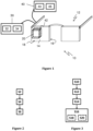
- the invention relates to a head mounted device 10 configured to be worn by a user and comprising an optical system 12 adapted to the user.
- the optical system 12 comprises at least an optical lens 14 designed to be placed in front of an eye of the user.
- the optical lens 14 comprises at least a back face 16 having an optical design and a front face 18 opposed to the back face 16 and having another optical design.
- a progressive ophthalmic lens design results of an optimization of a progressive surface so as to restore a presbyope's ability to see clearly at all distances but also to optimally respect all physiological visual functions such as foveal vision, extra-foveal vision, binocular vision and to minimize unwanted astigmatisms.
- a progressive lens design comprises:
- optical characteristics are part of the "designs" defined and calculated by ophthalmic lens designers and that are provided with the progressive lenses.
- the dioptric function corresponds to the optical lens power (mean power, astigmatism etc... ) as a function of the gaze direction and results of the combination of the optical designs of the front and the back faces of the optical lens.
- the optical function corresponds to a function providing for each gaze direction the effect of the optical lens on the light ray passing through the optical lens and depending on the combination of the optical designs of the front and the back faces of the optical lens.
- the optical function may comprise as dioptric function, light absorption, polarizing capability, reinforcement of contrast capacity, etc...
- the front and the back faces are designed and arranged so as to form an ophthalmic lens adapted to the user's prescription.
- the ophthalmic lens is a progressive optical lens and/or a multifocal optical lens.
- the optical system 12 further comprises a see-through displaying device 20 designed and configured to display a virtual image towards the eye of the user.
- the virtual image is transmitted at least through the back face 16 of the optical lens 14 defining a display area on the back face 16.
- the see-through displaying device 20 comprises a display device comprising a display source (not illustrated), a collimating source (not illustrated) and a light conducting element (not illustrated).
- the light conducting element is configured to output a supplementary light through an exit face of said light conducting element towards an eye of the wearer.
- the light conducting element can be a light-guide optical element (LOE).
- Such display system allows a two-dimensional image source to be imaged to infinity or not and reflected towards the eye of the wearer.
- the optical see-through display device 20 allows the user to interact with its environment while displaying information to the user.
- the device displays an image of the environment of the user with augmented reality based on a source image.
- the optical system 12 comprises a correction determining component 30 configured to determine a correcting optical function to be applied on a virtual image to be displayed to a user by the see-through displaying device 20.
- the correction determining component 30 comprises a memory 32 configured to store computer executable instructions, and a processor 34 for executing the computer executable instructions stored in the memory 32.
- the computer executable instructions comprise instructions for:
- the computer executable instructions further comprise one of the following instructions for:
- the optical system 12 further comprises an optical system adjusting component 40 configured to adjust the optical system based on the determined correcting optical function.
- the optical system adjusting component 40 comprises an optical device 42 designed to be placed such that the virtual image is further transmitted through the optical device.
- the optical device 42 has an optical function based on the determined correcting optical function.
- the optical system adjusting component 40 comprises:
- the computer executable instructions comprise instructions for processing a virtual source image from which the virtual image is displayed, based on the determined correcting optical function.
- the method is destined to be implemented by computer means and allows the determination of a correcting optical function to be applied on a virtual image to be displayed to a user of an optical system as described hereinbefore.
- the method comprises:
- optical design data providing step S2 optical design data relating to the optical design of the back face of the optical lens are provided.
- display area data relative to at least one parameter of the display area are provided during the display area data providing step S4.
- the parameter of the display area can be:
- the correcting optical function is determined based at least on the optical design data and on the display area data during the correcting optical function determining step S6.
- optical design data relating to the optical design of the front face of the optical lens is further provided during the optical design data providing step S2.
- the correcting optical function is further determined based on the optical design data relating to the optical design of the front face of the optical lens.
- the invention further relates to a method for providing an optical system 12 adapted to a user as described hereinbefore.
- the method comprises at least:
- the optical lens 14 is provided, the optical lens being already designed to be placed in front of an eye of the user.
- a see-through displaying device 20 is provided during the see-through displaying device providing step S12.
- the see-through displaying device 20 is designed and configured to display the virtual image towards the eye of the user such that the virtual image being transmitted at least through the back face 16 of the optical lens 14.
- a correcting optical function to be applied on a virtual image to be displayed to the user the optical system 12 is determined according to the method described hereinbefore.
- the optical system 12 is adjusted based on the determined correcting optical function during the optical system adjusting step S16.
- the optical system adjusting step S16 further comprises an optical device providing step S18, during which an optical device 42 is provided.
- the optical device 42 is previously designed to be placed such that the virtual image is further transmitted through the optical device and the optical device 42 has an optical function based on the determined correcting optical function.
- the optical system adjusting step S16 comprises a virtual source image processing step S20, during which a virtual source image from which the virtual image is displayed is processed based on the determined correcting optical function.
- the optical lens is an active optical lens having a programmable optical function controlled by an optical function controller.
- Such active optical lens has the advantage to be more personalized to the wearer according to its viewing conditions and/or its activity.
- optical design data relating to the optical design of the back face are provided over time during the optical design data providing step S2.
- the correcting optical function is determined and thus updated based on the evolution over time of the optical design data during the correcting optical function determining step.
- the optical function of the optical device can also be updated based on the updated correcting optical function during the optical device providing step S18 if the optical device is also an active optical lens having a programmable optical function.
- the processing of the virtual source image can be updated based on the updated correcting optical function during the virtual source image processing step S20.
Landscapes
- Physics & Mathematics (AREA)
- General Physics & Mathematics (AREA)
- Optics & Photonics (AREA)
- Health & Medical Sciences (AREA)
- Ophthalmology & Optometry (AREA)
- General Health & Medical Sciences (AREA)
- Eyeglasses (AREA)
Claims (10)
- Procédé destiné à obtenir un système optique adapté à un utilisateur, le système optique (12) comprenant au moins une lentille optique (14) et un dispositif d'affichage transparent (20), le procédé comprenant au moins :- une étape d'obtention de lentille optique (S10), pendant laquelle la lentille optique (14) qui est une lentille optique active ayant une fonction optique programmable contrôlée par un contrôleur de fonction optique est obtenue, la lentille optique (14) étant conçue pour être placée devant un œil de l'utilisateur et comprenant au moins une face arrière (16) ayant une conception optique et une face avant (18), à l'opposé de la face arrière (16), ayant une autre conception optique, la conception optique comprenant un ensemble de paramètres permettant de définir une fonction dioptrique d'une lentille ophtalmique ;- une étape d'obtention de dispositif d'affichage transparent (S12), pendant laquelle un dispositif d'affichage transparent (20) est obtenu, le dispositif d'affichage transparent (20) étant conçu et configuré pour afficher l'image virtuelle vers l'œil de l'utilisateur, l'image virtuelle étant transmise au moins à travers la face arrière (16) et la face avant (18) de la lentille optique (14) définissant une zone d'affichage sur la face arrière (16) ;- une étape de détermination de fonction optique de correction (S14), pendant laquelle une fonction optique de correction devant être appliquée sur une image virtuelle devant être affichée pour l'utilisateur du système optique (12) est déterminée ;- une étape d'ajustement de système optique (S16), pendant laquelle le système optique (12) est ajusté sur la base de la fonction optique de correction déterminée, dans lequel la détermination de la fonction optique de correction comprend :- une étape d'obtention de données de conception optique (S2), pendant laquelle des données de conception optique relatives à la conception optique de la face avant et de la face arrière de la lentille optique sont obtenues ;- une étape d'obtention de données de zone d'affichage (S4), pendant laquelle des données de zone d'affichage relatives à au moins un paramètre de la zone d'affichage sont obtenues ; et- une étape de détermination de fonction optique de correction (S6), pendant laquelle une fonction optique de correction est déterminée au moins sur la base des données de conception optique de la face avant (18) et de la face arrière (16) et des données de zone d'affichage.
- Procédé selon la revendication 1, dans lequel les faces avant et arrière sont conçues et agencées de manière à former une lentille ophtalmique adaptée à la prescription de l'utilisateur.
- Procédé selon la revendication 2, dans lequel la lentille ophtalmique est une lentille optique progressive et/ou une lentille optique multifocale.
- Procédé selon l'une quelconque des revendications 1 à 3 précédentes, dans lequel l'au moins un paramètre de la zone d'affichage comprend la position relative de la zone d'affichage au moins par rapport à la face arrière et/ou l'étendue angulaire relative de la zone d'affichage au moins par rapport à la face arrière et/ou la distance de projection de l'image virtuelle.
- Procédé selon l'une quelconque des revendications 1 à 4, dans lequel l'étape d'ajustement de système optique (S16) comprend une étape d'obtention de dispositif optique (S18), pendant laquelle un dispositif optique (42) est obtenu, le dispositif optique (42) étant conçu pour être placé de telle sorte que l'image virtuelle est également transmise à travers le dispositif optique (42) et le dispositif optique ayant une fonction optique basée sur la fonction optique de correction déterminée.
- Procédé selon l'une quelconque des revendications 1 à 5, dans lequel l'étape d'ajustement de système optique (S16) comprend une étape de traitement d'image virtuelle source (S20), pendant laquelle une image virtuelle source à partir de laquelle l'image virtuelle est affichée est traitée sur la base de la fonction optique de correction déterminée.
- Système optique (12) adapté à un utilisateur comprenant :- une lentille optique (14) qui est une lentille optique active ayant une fonction optique programmable contrôlée par un contrôleur de fonction optique, et conçue pour être placée devant un œil de l'utilisateur et comprenant au moins une face arrière (16) ayant une conception optique et une face avant (18), à l'opposé de la face arrière (16), ayant une autre conception optique, la conception optique comprend un ensemble de paramètres permettant de définir une fonction dioptrique d'une lentille ophtalmique ;- un dispositif d'affichage transparent (20) conçu et configuré pour afficher une image virtuelle vers l'œil de l'utilisateur, l'image virtuelle étant transmise au moins à travers la face arrière (16) et la face avant (18) de la lentille optique (14) définissant une zone d'affichage sur la face arrière ;- un composant de détermination de correction (30) configuré pour déterminer une fonction optique de correction devant être appliquée sur une image virtuelle devant être affichée pour un utilisateur par le dispositif d'affichage transparent ; et- un composant d'ajustement de système optique (40) configuré pour ajuster le système optique sur la base de la fonction optique de correction déterminée,dans lequel le composant de détermination de correction (30) comprend :- une mémoire (32) configurée pour stocker des instructions exécutables par ordinateur, et- un processeur (34) servant à exécuter les instructions exécutables par ordinateur stockées dans la mémoire (32), dans lequel les instructions exécutables par ordinateur comprennent des instructions pour :• obtenir des données de conception optique relatives aux conceptions optiques de la face arrière (16) et de la face avant (18) de la lentille optique (14),• obtenir des données de zone d'affichage relatives à au moins un paramètre de la zone d'affichage, et- déterminer une fonction optique de correction au moins sur la base des données de conception optique de la face avant (18) et de la face arrière (16) et des données de zone d'affichage.
- Système optique selon la revendication 7, dans lequel le composant d'ajustement de système optique (40) comprend un dispositif optique (42) conçu pour être placé de telle sorte que l'image virtuelle est également transmise à travers le dispositif optique et le dispositif optique (42) a une fonction optique basée sur la fonction optique de correction déterminée.
- Système optique selon la revendication 7 ou 8, dans lequel le composant d'ajustement de système optique (40) comprend :- une mémoire (44) configurée pour stocker des instructions exécutables par ordinateur, et- un processeur (46) servant à exécuter les instructions exécutables par ordinateur stockées dans la mémoire, dans lequel les instructions exécutables par ordinateur comprennent des instructions pour traiter une image virtuelle source à partir de laquelle l'image virtuelle est affichée, sur la base de la fonction optique de correction déterminée.
- Dispositif facial (10) configuré pour être porté par un utilisateur, comprenant un système optique (12) adapté à l'utilisateur selon l'une quelconque des revendications 7 à 9 précédentes.
Priority Applications (6)
| Application Number | Priority Date | Filing Date | Title |
|---|---|---|---|
| EP16306192.2A EP3296793B1 (fr) | 2016-09-19 | 2016-09-19 | Procédé de détermination d'une fonction optique de correction sur une image virtuelle |
| US16/330,221 US10852549B2 (en) | 2016-09-19 | 2017-09-12 | Method of determining a correcting optical function to a virtual image |
| CN201780056125.8A CN109690388B (zh) | 2016-09-19 | 2017-09-12 | 确定用于虚拟图像的矫正光学功能的方法 |
| KR1020197005592A KR102511897B1 (ko) | 2016-09-19 | 2017-09-12 | 가상 이미지에 대한 교정 광학 기능을 결정하는 방법 |
| PCT/EP2017/072812 WO2018050611A1 (fr) | 2016-09-19 | 2017-09-12 | Procédé de détermination d'une fonction optique de correction sur une image virtuelle |
| JP2019513021A JP7440261B2 (ja) | 2016-09-19 | 2017-09-12 | 仮想画像に対する補正光学機能を決定する方法 |
Applications Claiming Priority (1)
| Application Number | Priority Date | Filing Date | Title |
|---|---|---|---|
| EP16306192.2A EP3296793B1 (fr) | 2016-09-19 | 2016-09-19 | Procédé de détermination d'une fonction optique de correction sur une image virtuelle |
Publications (2)
| Publication Number | Publication Date |
|---|---|
| EP3296793A1 EP3296793A1 (fr) | 2018-03-21 |
| EP3296793B1 true EP3296793B1 (fr) | 2025-05-21 |
Family
ID=57199925
Family Applications (1)
| Application Number | Title | Priority Date | Filing Date |
|---|---|---|---|
| EP16306192.2A Active EP3296793B1 (fr) | 2016-09-19 | 2016-09-19 | Procédé de détermination d'une fonction optique de correction sur une image virtuelle |
Country Status (6)
| Country | Link |
|---|---|
| US (1) | US10852549B2 (fr) |
| EP (1) | EP3296793B1 (fr) |
| JP (1) | JP7440261B2 (fr) |
| KR (1) | KR102511897B1 (fr) |
| CN (1) | CN109690388B (fr) |
| WO (1) | WO2018050611A1 (fr) |
Families Citing this family (5)
| Publication number | Priority date | Publication date | Assignee | Title |
|---|---|---|---|---|
| JP7274724B2 (ja) | 2016-12-31 | 2023-05-17 | ルムス エルティーディー. | 導光光学素子を介したレチナールイメージングに基づく目の追跡具 |
| WO2018138714A1 (fr) * | 2017-01-28 | 2018-08-02 | Lumus Ltd. | Système d'imagerie à réalité augmentée |
| IL259518B2 (en) | 2018-05-22 | 2023-04-01 | Lumus Ltd | Optical system and method for improving light field uniformity |
| DE102020214707A1 (de) | 2020-11-24 | 2022-05-25 | Hochschule Bremen | Verfahren und Vorrichtung zur rechnergestützten Simulation einer Sehhilfe für einen Benutzer mit Sehfehler mittels einer auf seinem Kopf getragenen Vorrichtung |
| DE102022118646B3 (de) | 2022-07-26 | 2024-02-01 | Hochschule Bremen, Körperschaft des öffentlichen Rechts | Verfahren und Vorrichtung zur Analyse eines oder mehrerer Brillengläser |
Citations (2)
| Publication number | Priority date | Publication date | Assignee | Title |
|---|---|---|---|---|
| EP2343591A1 (fr) * | 2009-12-23 | 2011-07-13 | ESSILOR INTERNATIONAL (Compagnie Générale d'Optique) | Loupe adaptée pour la fourniture d'une vision ophtalmique et d'une vision supplémentaire |
| EP2819402A1 (fr) * | 2012-02-22 | 2014-12-31 | Sony Corporation | Appareil d'affichage, appareil de traitement d'image, procédé de traitement d'image et programme informatique |
Family Cites Families (9)
| Publication number | Priority date | Publication date | Assignee | Title |
|---|---|---|---|---|
| JP5341462B2 (ja) | 2008-10-14 | 2013-11-13 | キヤノン株式会社 | 収差補正方法、画像処理装置および画像処理システム |
| US20110213664A1 (en) * | 2010-02-28 | 2011-09-01 | Osterhout Group, Inc. | Local advertising content on an interactive head-mounted eyepiece |
| JP5994715B2 (ja) * | 2012-04-10 | 2016-09-21 | パナソニックIpマネジメント株式会社 | 計算機ホログラム型表示装置 |
| US10520730B2 (en) * | 2013-09-04 | 2019-12-31 | Essilor International | Methods and systems for augmented reality |
| DE102013219624B3 (de) * | 2013-09-27 | 2015-01-22 | Carl Zeiss Ag | Brillenglas für eine auf den Kopf eines Benutzers aufsetzbare und ein Bild erzeugende Anzeigevorrichtung sowie Anzeigevorrichtung mit einem solchen Brillenglas |
| EP3087312B1 (fr) * | 2013-12-23 | 2024-09-11 | Essilor International | Visiocasque avec fonction de filtre |
| JP2015219489A (ja) * | 2014-05-21 | 2015-12-07 | 株式会社東芝 | 表示装置 |
| ES2977458T3 (es) * | 2014-09-22 | 2024-08-23 | Hoya Lens Thailand Ltd | Procedimiento de diseño y fabricación de una lente de potencia progresiva |
| CN104243959B (zh) * | 2014-10-08 | 2016-04-06 | 原硕朋 | 基于偏振定向和组合定位的智能复合眼镜 |
-
2016
- 2016-09-19 EP EP16306192.2A patent/EP3296793B1/fr active Active
-
2017
- 2017-09-12 CN CN201780056125.8A patent/CN109690388B/zh active Active
- 2017-09-12 JP JP2019513021A patent/JP7440261B2/ja active Active
- 2017-09-12 KR KR1020197005592A patent/KR102511897B1/ko active Active
- 2017-09-12 US US16/330,221 patent/US10852549B2/en active Active
- 2017-09-12 WO PCT/EP2017/072812 patent/WO2018050611A1/fr not_active Ceased
Patent Citations (2)
| Publication number | Priority date | Publication date | Assignee | Title |
|---|---|---|---|---|
| EP2343591A1 (fr) * | 2009-12-23 | 2011-07-13 | ESSILOR INTERNATIONAL (Compagnie Générale d'Optique) | Loupe adaptée pour la fourniture d'une vision ophtalmique et d'une vision supplémentaire |
| EP2819402A1 (fr) * | 2012-02-22 | 2014-12-31 | Sony Corporation | Appareil d'affichage, appareil de traitement d'image, procédé de traitement d'image et programme informatique |
Also Published As
| Publication number | Publication date |
|---|---|
| KR102511897B1 (ko) | 2023-03-20 |
| KR20190046813A (ko) | 2019-05-07 |
| JP2019529984A (ja) | 2019-10-17 |
| EP3296793A1 (fr) | 2018-03-21 |
| US10852549B2 (en) | 2020-12-01 |
| US20190227326A1 (en) | 2019-07-25 |
| JP7440261B2 (ja) | 2024-02-28 |
| WO2018050611A1 (fr) | 2018-03-22 |
| CN109690388B (zh) | 2021-04-27 |
| CN109690388A (zh) | 2019-04-26 |
Similar Documents
| Publication | Publication Date | Title |
|---|---|---|
| EP3296792B1 (fr) | Procédé de gestion de l'affichage d'une image pour l'utilisateur d'un système optique | |
| EP3241064B1 (fr) | Lentille ophtalmique de lunettes avec addition progressive temporale | |
| EP3126901B1 (fr) | Procédé de calcul d'un système optique selon un cadre de lunettes donné | |
| US10852549B2 (en) | Method of determining a correcting optical function to a virtual image | |
| EP2772793B1 (fr) | Procédé pour optimiser le prisme postural d'une lentille ophtalmique | |
| JP6920287B2 (ja) | 眼科用レンズの3次元性能を判定する方法と、これに関連する眼科用レンズの計算方法 | |
| WO2014019968A1 (fr) | Verre correcteur progressif | |
| EP3304180B1 (fr) | Procédé permettant de modifier un paramètre non-dioptrique d'un système optique | |
| WO2020254513A1 (fr) | Procédé et système de détermination d'un élément ophtalmique adapté à un porteur | |
| EP3268803B1 (fr) | Procédé permettant de déterminer une paire de lentilles ophtalmiques | |
| EP3953760A2 (fr) | Procédés et systèmes pour optimiser une fonction optique d'une lentille ophtalmique progressive dans des conditions de port spécifiques |
Legal Events
| Date | Code | Title | Description |
|---|---|---|---|
| PUAI | Public reference made under article 153(3) epc to a published international application that has entered the european phase |
Free format text: ORIGINAL CODE: 0009012 |
|
| STAA | Information on the status of an ep patent application or granted ep patent |
Free format text: STATUS: THE APPLICATION HAS BEEN PUBLISHED |
|
| AK | Designated contracting states |
Kind code of ref document: A1 Designated state(s): AL AT BE BG CH CY CZ DE DK EE ES FI FR GB GR HR HU IE IS IT LI LT LU LV MC MK MT NL NO PL PT RO RS SE SI SK SM TR |
|
| AX | Request for extension of the european patent |
Extension state: BA ME |
|
| STAA | Information on the status of an ep patent application or granted ep patent |
Free format text: STATUS: REQUEST FOR EXAMINATION WAS MADE |
|
| 17P | Request for examination filed |
Effective date: 20180920 |
|
| RBV | Designated contracting states (corrected) |
Designated state(s): AL AT BE BG CH CY CZ DE DK EE ES FI FR GB GR HR HU IE IS IT LI LT LU LV MC MK MT NL NO PL PT RO RS SE SI SK SM TR |
|
| STAA | Information on the status of an ep patent application or granted ep patent |
Free format text: STATUS: EXAMINATION IS IN PROGRESS |
|
| 17Q | First examination report despatched |
Effective date: 20210813 |
|
| P01 | Opt-out of the competence of the unified patent court (upc) registered |
Effective date: 20230525 |
|
| GRAP | Despatch of communication of intention to grant a patent |
Free format text: ORIGINAL CODE: EPIDOSNIGR1 |
|
| STAA | Information on the status of an ep patent application or granted ep patent |
Free format text: STATUS: GRANT OF PATENT IS INTENDED |
|
| INTG | Intention to grant announced |
Effective date: 20250114 |
|
| GRAS | Grant fee paid |
Free format text: ORIGINAL CODE: EPIDOSNIGR3 |
|
| GRAA | (expected) grant |
Free format text: ORIGINAL CODE: 0009210 |
|
| STAA | Information on the status of an ep patent application or granted ep patent |
Free format text: STATUS: THE PATENT HAS BEEN GRANTED |
|
| AK | Designated contracting states |
Kind code of ref document: B1 Designated state(s): AL AT BE BG CH CY CZ DE DK EE ES FI FR GB GR HR HU IE IS IT LI LT LU LV MC MK MT NL NO PL PT RO RS SE SI SK SM TR |
|
| REG | Reference to a national code |
Ref country code: GB Ref legal event code: FG4D |
|
| REG | Reference to a national code |
Ref country code: CH Ref legal event code: EP |
|
| REG | Reference to a national code |
Ref country code: DE Ref legal event code: R096 Ref document number: 602016092298 Country of ref document: DE |
|
| REG | Reference to a national code |
Ref country code: IE Ref legal event code: FG4D |
|
| REG | Reference to a national code |
Ref country code: NL Ref legal event code: MP Effective date: 20250521 |
|
| PG25 | Lapsed in a contracting state [announced via postgrant information from national office to epo] |
Ref country code: PT Free format text: LAPSE BECAUSE OF FAILURE TO SUBMIT A TRANSLATION OF THE DESCRIPTION OR TO PAY THE FEE WITHIN THE PRESCRIBED TIME-LIMIT Effective date: 20250922 Ref country code: ES Free format text: LAPSE BECAUSE OF FAILURE TO SUBMIT A TRANSLATION OF THE DESCRIPTION OR TO PAY THE FEE WITHIN THE PRESCRIBED TIME-LIMIT Effective date: 20250521 Ref country code: FI Free format text: LAPSE BECAUSE OF FAILURE TO SUBMIT A TRANSLATION OF THE DESCRIPTION OR TO PAY THE FEE WITHIN THE PRESCRIBED TIME-LIMIT Effective date: 20250521 |
|
| PGFP | Annual fee paid to national office [announced via postgrant information from national office to epo] |
Ref country code: DE Payment date: 20250929 Year of fee payment: 10 |
|
| REG | Reference to a national code |
Ref country code: LT Ref legal event code: MG9D |
|
| PG25 | Lapsed in a contracting state [announced via postgrant information from national office to epo] |
Ref country code: NO Free format text: LAPSE BECAUSE OF FAILURE TO SUBMIT A TRANSLATION OF THE DESCRIPTION OR TO PAY THE FEE WITHIN THE PRESCRIBED TIME-LIMIT Effective date: 20250821 Ref country code: GR Free format text: LAPSE BECAUSE OF FAILURE TO SUBMIT A TRANSLATION OF THE DESCRIPTION OR TO PAY THE FEE WITHIN THE PRESCRIBED TIME-LIMIT Effective date: 20250822 |
|
| PG25 | Lapsed in a contracting state [announced via postgrant information from national office to epo] |
Ref country code: NL Free format text: LAPSE BECAUSE OF FAILURE TO SUBMIT A TRANSLATION OF THE DESCRIPTION OR TO PAY THE FEE WITHIN THE PRESCRIBED TIME-LIMIT Effective date: 20250521 Ref country code: PL Free format text: LAPSE BECAUSE OF FAILURE TO SUBMIT A TRANSLATION OF THE DESCRIPTION OR TO PAY THE FEE WITHIN THE PRESCRIBED TIME-LIMIT Effective date: 20250521 |
|
| PGFP | Annual fee paid to national office [announced via postgrant information from national office to epo] |
Ref country code: IT Payment date: 20250919 Year of fee payment: 10 |
|
| PG25 | Lapsed in a contracting state [announced via postgrant information from national office to epo] |
Ref country code: BG Free format text: LAPSE BECAUSE OF FAILURE TO SUBMIT A TRANSLATION OF THE DESCRIPTION OR TO PAY THE FEE WITHIN THE PRESCRIBED TIME-LIMIT Effective date: 20250521 |
|
| PGFP | Annual fee paid to national office [announced via postgrant information from national office to epo] |
Ref country code: GB Payment date: 20250929 Year of fee payment: 10 |
|
| PG25 | Lapsed in a contracting state [announced via postgrant information from national office to epo] |
Ref country code: HR Free format text: LAPSE BECAUSE OF FAILURE TO SUBMIT A TRANSLATION OF THE DESCRIPTION OR TO PAY THE FEE WITHIN THE PRESCRIBED TIME-LIMIT Effective date: 20250521 |
|
| PGFP | Annual fee paid to national office [announced via postgrant information from national office to epo] |
Ref country code: FR Payment date: 20250925 Year of fee payment: 10 |
|
| PG25 | Lapsed in a contracting state [announced via postgrant information from national office to epo] |
Ref country code: RS Free format text: LAPSE BECAUSE OF FAILURE TO SUBMIT A TRANSLATION OF THE DESCRIPTION OR TO PAY THE FEE WITHIN THE PRESCRIBED TIME-LIMIT Effective date: 20250821 |
|
| PG25 | Lapsed in a contracting state [announced via postgrant information from national office to epo] |
Ref country code: IS Free format text: LAPSE BECAUSE OF FAILURE TO SUBMIT A TRANSLATION OF THE DESCRIPTION OR TO PAY THE FEE WITHIN THE PRESCRIBED TIME-LIMIT Effective date: 20250921 |
|
| PG25 | Lapsed in a contracting state [announced via postgrant information from national office to epo] |
Ref country code: LV Free format text: LAPSE BECAUSE OF FAILURE TO SUBMIT A TRANSLATION OF THE DESCRIPTION OR TO PAY THE FEE WITHIN THE PRESCRIBED TIME-LIMIT Effective date: 20250521 |
|
| REG | Reference to a national code |
Ref country code: AT Ref legal event code: MK05 Ref document number: 1797220 Country of ref document: AT Kind code of ref document: T Effective date: 20250521 |
|
| PG25 | Lapsed in a contracting state [announced via postgrant information from national office to epo] |
Ref country code: AT Free format text: LAPSE BECAUSE OF FAILURE TO SUBMIT A TRANSLATION OF THE DESCRIPTION OR TO PAY THE FEE WITHIN THE PRESCRIBED TIME-LIMIT Effective date: 20250521 Ref country code: SM Free format text: LAPSE BECAUSE OF FAILURE TO SUBMIT A TRANSLATION OF THE DESCRIPTION OR TO PAY THE FEE WITHIN THE PRESCRIBED TIME-LIMIT Effective date: 20250521 Ref country code: DK Free format text: LAPSE BECAUSE OF FAILURE TO SUBMIT A TRANSLATION OF THE DESCRIPTION OR TO PAY THE FEE WITHIN THE PRESCRIBED TIME-LIMIT Effective date: 20250521 |
|
| PG25 | Lapsed in a contracting state [announced via postgrant information from national office to epo] |
Ref country code: CZ Free format text: LAPSE BECAUSE OF FAILURE TO SUBMIT A TRANSLATION OF THE DESCRIPTION OR TO PAY THE FEE WITHIN THE PRESCRIBED TIME-LIMIT Effective date: 20250521 |
|
| PG25 | Lapsed in a contracting state [announced via postgrant information from national office to epo] |
Ref country code: EE Free format text: LAPSE BECAUSE OF FAILURE TO SUBMIT A TRANSLATION OF THE DESCRIPTION OR TO PAY THE FEE WITHIN THE PRESCRIBED TIME-LIMIT Effective date: 20250521 |
|
| PG25 | Lapsed in a contracting state [announced via postgrant information from national office to epo] |
Ref country code: SK Free format text: LAPSE BECAUSE OF FAILURE TO SUBMIT A TRANSLATION OF THE DESCRIPTION OR TO PAY THE FEE WITHIN THE PRESCRIBED TIME-LIMIT Effective date: 20250521 Ref country code: RO Free format text: LAPSE BECAUSE OF FAILURE TO SUBMIT A TRANSLATION OF THE DESCRIPTION OR TO PAY THE FEE WITHIN THE PRESCRIBED TIME-LIMIT Effective date: 20250521 |
|
| REG | Reference to a national code |
Ref country code: DE Ref legal event code: R097 Ref document number: 602016092298 Country of ref document: DE |
|
| PLBE | No opposition filed within time limit |
Free format text: ORIGINAL CODE: 0009261 |
|
| STAA | Information on the status of an ep patent application or granted ep patent |
Free format text: STATUS: NO OPPOSITION FILED WITHIN TIME LIMIT |
|
| REG | Reference to a national code |
Ref country code: CH Ref legal event code: L10 Free format text: ST27 STATUS EVENT CODE: U-0-0-L10-L00 (AS PROVIDED BY THE NATIONAL OFFICE) Effective date: 20260402 |
|
| 26N | No opposition filed |
Effective date: 20260224 |
|
| REG | Reference to a national code |
Ref country code: CH Ref legal event code: H13 Free format text: ST27 STATUS EVENT CODE: U-0-0-H10-H13 (AS PROVIDED BY THE NATIONAL OFFICE) Effective date: 20260504 |