EP3296844A1 - Dispositif de terminal, cachet électronique et programme - Google Patents
Dispositif de terminal, cachet électronique et programme Download PDFInfo
- Publication number
- EP3296844A1 EP3296844A1 EP15891863.1A EP15891863A EP3296844A1 EP 3296844 A1 EP3296844 A1 EP 3296844A1 EP 15891863 A EP15891863 A EP 15891863A EP 3296844 A1 EP3296844 A1 EP 3296844A1
- Authority
- EP
- European Patent Office
- Prior art keywords
- stamp
- pressing
- pressed down
- positional relationship
- touch panel
- Prior art date
- Legal status (The legal status is an assumption and is not a legal conclusion. Google has not performed a legal analysis and makes no representation as to the accuracy of the status listed.)
- Withdrawn
Links
Images



Classifications
-
- G—PHYSICS
- G06—COMPUTING OR CALCULATING; COUNTING
- G06F—ELECTRIC DIGITAL DATA PROCESSING
- G06F3/00—Input arrangements for transferring data to be processed into a form capable of being handled by the computer; Output arrangements for transferring data from processing unit to output unit, e.g. interface arrangements
- G06F3/01—Input arrangements or combined input and output arrangements for interaction between user and computer
- G06F3/03—Arrangements for converting the position or the displacement of a member into a coded form
- G06F3/041—Digitisers, e.g. for touch screens or touch pads, characterised by the transducing means
-
- G—PHYSICS
- G06—COMPUTING OR CALCULATING; COUNTING
- G06F—ELECTRIC DIGITAL DATA PROCESSING
- G06F21/00—Security arrangements for protecting computers, components thereof, programs or data against unauthorised activity
- G06F21/30—Authentication, i.e. establishing the identity or authorisation of security principals
- G06F21/31—User authentication
-
- G—PHYSICS
- G06—COMPUTING OR CALCULATING; COUNTING
- G06F—ELECTRIC DIGITAL DATA PROCESSING
- G06F3/00—Input arrangements for transferring data to be processed into a form capable of being handled by the computer; Output arrangements for transferring data from processing unit to output unit, e.g. interface arrangements
- G06F3/01—Input arrangements or combined input and output arrangements for interaction between user and computer
- G06F3/048—Interaction techniques based on graphical user interfaces [GUI]
- G06F3/0487—Interaction techniques based on graphical user interfaces [GUI] using specific features provided by the input device, e.g. functions controlled by the rotation of a mouse with dual sensing arrangements, or of the nature of the input device, e.g. tap gestures based on pressure sensed by a digitiser
- G06F3/0488—Interaction techniques based on graphical user interfaces [GUI] using specific features provided by the input device, e.g. functions controlled by the rotation of a mouse with dual sensing arrangements, or of the nature of the input device, e.g. tap gestures based on pressure sensed by a digitiser using a touch-screen or digitiser, e.g. input of commands through traced gestures
-
- G—PHYSICS
- G06—COMPUTING OR CALCULATING; COUNTING
- G06F—ELECTRIC DIGITAL DATA PROCESSING
- G06F2203/00—Indexing scheme relating to G06F3/00 - G06F3/048
- G06F2203/041—Indexing scheme relating to G06F3/041 - G06F3/045
- G06F2203/04104—Multi-touch detection in digitiser, i.e. details about the simultaneous detection of a plurality of touching locations, e.g. multiple fingers or pen and finger
Definitions
- the present invention relates to a terminal device, an electronic stamp and a program, in which a multi-touch adaptive touch panel implemented on the terminal device performs predetermined control on the condition that a plurality of positions detected by the fact that electronic stamps are being pressed down are in a predetermined relative positional relationship.
- an example of the applied services using electronic stamps includes an electronic ticket system as disclosed in Patent Document 2.
- a terminal device on which an electronic ticket is displayed by activating a dedicated electronic ticket application, is presented to a staff member at an entrance gate at a venue for concerts or the like, and admission into the venue is allowed by the staff member causing an electronic stamp to make contact therewith so as to cause transition to a "used ticket" display.
- a time-consuming paper-based ticket collecting can be replaced by the simple work of a staff member causing a stamp to make contact with a touch panel, and thus, the admission procedure can be performed more smoothly.
- a second object of the present invention is to provide a terminal device, an electronic stamp and a program, in which fraudulent sealing is difficult.
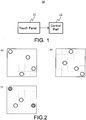
- Fig. 1 is a diagram illustrating a configuration of a terminal device 10 according to the present invention.
- the terminal device 10 includes at least a touch panel 11 and a control part 12, and it also incorporates various other functions according to the applications of the terminal device 10.
- the touch panel 11 is a multi-touch type touch panel that is capable of simultaneously detecting touches or pressing-downs at a plurality of positions.
- Detection methods of the touch panel include a method in which detection is made by causing a statically conductive object to make contact therewith (e.g., a capacitance method), a method in which detection is made by the touch panel being pressed down (e.g., a resistive film method), and the like; however, any method is sufficient as long as it is capable of simultaneously detecting touches or pressing-downs at a plurality of positions.
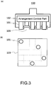
- the control part 12 performs predetermined control on the condition that, subsequent to the detection of touches or pressing-downs at a plurality of positions having a predetermined relative positional relationship (e.g., Fig. 2(a) ) on the touch panel 11, touches or pressing-downs at a plurality of positions having another predetermined relative positional relationship (e.g., Fig. 2(b) ) are detected.
- a predetermined relative positional relationship e.g., Fig. 2(a)
- Fig. 2(b) a predetermined relative positional relationship
- the significance of relatively defining the positional relationships is that, because sealing of an electronic stamp onto the touch panel is conducted by a human being and thus, the sealing orientation is not always the same, the relative definition of the positional relationships would allow authentication without relying on the sealing orientation.
- the specific arrangement of each positional relationship is arbitrary. It should be noted that the content of the relative positional relationship and the another relative positional relationship may be held by the control part 12 itself, or a storage means of the terminal device 10 may hold the same and it may be read out therefrom. Moreover, other devices such as a server, or the like, via a network may hold the same and it may be read out therefrom. From the viewpoint of preventing fraudulent input, it may be advisable to limit the time until when the another predetermined relative positional relationship is detected subsequent to touches or pressing-downs at a plurality of positions having the predetermined relative positional relationship being detected.
- the time is set to be as short as possible.
- the content of the predetermined control in the case of successful authentication is also arbitrary and examples of such predetermined control include changing the screen display, receiving/sending predetermined information, or the like.
- authentication for execution of control is performed on the condition that, subsequent to the above-described detection, touches or pressing-downs at a plurality of positions having another predetermined relative positional relationship are detected.
- a plurality of absolute positions on the touch panel 11, which are touched or pressed down in the predetermined relative positional relationship, and a plurality of absolute positions on the touch panel 11, which are touched or pressed down in another predetermined relative positional relationship may share at least one common position, and this may be used as a condition for the authentication.
- Fig. 2(c) shows an example where, with respect to the predetermined relative positional relationship shown in Fig. 2(a) , another predetermined relative positional relationship shares two common positions (shaded positions) therewith.
- An electronic stamp includes a plurality of members arranged in predetermined relative positional relationship, and by touching or pressing down the touch panel of the terminal device with such plurality of members, the terminal device is allowed to detect the touches or pressing-downs at a plurality of positions having the predetermined relative positional relationship.
- the electronic stamp is configured such that the arrangement of the plurality of members arranged in the predetermined relative positional relationship is automatically or semi-automatically changeable to an arrangement of another predetermined relative positional relationship.
- General examples of the method of changing the arrangement of the plurality of members from the predetermined relative positional relationship to the another predetermined relative positional relationship include, among others: a method of preparing two electronic stamps having different arrangements for the plurality of members; or a method of manually changing the arrangements of the members by making the members configuring the electronic stamp removable within one single electronic stamp.
- a method of preparing two electronic stamps having different arrangements for the plurality of members or a method of manually changing the arrangements of the members by making the members configuring the electronic stamp removable within one single electronic stamp.
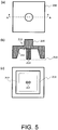
- Fig. 3(a) is a cross-section illustrating an example of an electronic stamp 100.
- the electronic stamp 100 includes a plurality of members 101 arranged in the predetermined relative positional relationship and an arrangement control part 102.
- Fig. 3(b) is a diagram illustrating an example arrangement of the plurality of members 101 in the bottom of the electronic stamp 100, namely, in a surface 103 configuring the stamp.
- the material of the plurality of members 101 needs to be statically conductive if the detection method of the touch panel 11, to which the electronic stamp 100 is applied, is by means of detecting touches/contacts of a statically conductive object; however, any material may be used if such detection method is by means of detecting pressing-downs of the touch panel.
- any shape can be used for the plurality of members 101 in the surface 103 configuring the stamp, and the example in Fig. 3(b) employs a circular shape.
- the electronic stamp 100 causes the terminal device 10 to detect touches or pressing-downs at a plurality of positions having the predetermined relative positional relationship by the touch panel 11 of the terminal device 10 being touched or pressed down with the plurality of members of the electronic stamp 100.
- the electronic stamp 100 is configured such that the arrangement of the plurality of members 101 arranged in the predetermined relative positional relationship is automatically changeable to an arrangement of another predetermined relative positional relationship.
- the arrangement control part 102 detects, via the plurality of members 101, the fact that the plurality of members 101 arranged in the predetermined relative positional relationship have made contact with the touch panel 11 or have pressed down the touch panel 11, and, subsequent to the detection, the arrangement control part 102 changes the arrangement of the plurality of members 101 arranged in the predetermined relative positional relationship to an arrangement in the another predetermined relative positional relationship. For that reason, the predetermined relative positional relationship and the another predetermined relative positional relationship need to be registered in advance with the arrangement control part 102.
- the method of registering the relative positional relationships is arbitrary and examples thereof include, among others, the electronic stamp 100 itself incorporating a registering means, or externally obtaining the same via wireless communication.
- the method of changing the arrangement of the plurality of members 101 is also arbitrary.
- An example thereof includes, as shown in Fig. 3(a) , a method where the plurality of members 101 make vertical movements in a direction vertical to the stamp surface 103.
- the time period from the detection of touches or pressing-downs at a plurality of positions having the predetermined relative positional relationship to the change of the arrangement to the another predetermined relative positional relationship is also arbitrary; however, when a time limit is set at the terminal device 10, to which the electronic stamp is applied, such time period may be set within the time limit.
- the arrangement of the plurality of members 101 arranged in the predetermined relative positional relationship can be changed automatically and promptly to the arrangement in the another predetermined relative positional relationship.
- the arrangement control part 102 may be configured so as to control the arrangement of the plurality of members 101 in order to meet the above-described condition. Accordingly, the authentication condition can be met by continuing the sealing of the electronic stamp 100 to the touch panel 11 for a predetermined time.
- Fig. 4 is a perspective view illustrating an example of an electronic stamp 200. More specifically, Fig. 4(a) shows a normal state and Fig. 4(b) shows a pressed-down state.
- the electronic stamp 200 includes a pressing-down part 210, a plurality of transmission parts 220 and a moving part 230.
- the number of the transmission parts 220 may be determined arbitrarily in view of the sealing stability of a first stamp 231, the moving stability and slidability of the moving part 230, or the like.
- the pressing-down part 210 includes a first slope 212 and a second stamp 213 made up of the plurality of members arranged in the another predetermined relative positional relationship, in a concave part 211 that is formed facing a surface 215 at with which the first stamp 231 and the second stamp 213 are caused to make contact or to be pressed down (hereinafter referred to as the "surface 215").
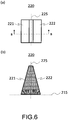
- Fig. 5 shows a configuration example of the pressing-down part 210. More specifically, Fig. 5(a) shows a plan view of the pressing-down part 210, Fig. 5(b) shows a cross-sectional view along line A-A and Fig. 5(c) shows a bottom view.
- the pressing-down part 210 is shown to have a square planar shape in Fig. 5 ; however, any shape may be employed.
- the opening of the concave part 211 is also shown to have a square shape in Fig. 5(c) ; however, any shape, including a circle or the like, may be employed as long as the sliding of a second slope 221 of the transmission part 220 along the first slope 212 is not hindered.
- the material of the plurality of members configuring the second stamp 213 needs to be statically conductive if the detection method of the touch panel 11, to which the electronic stamp 200 is applied, is by means of detecting touches/contacts of a statically conductive object; however, any material may be used if such detection method is by means of detecting pressing-downs of the touch panel.
- the number and arrangement of the members configuring the second stamp 213 are arbitrary and the shape of the plurality of members in the surface facing the surface 215 of the second stamp 213 is also arbitrary.
- Figs. 5(b) and 5(c) show two members and the shape of the members is circular.
- the transmission part 220 includes a second slope 221 and a third slope 222 that are inclined so as to broaden in opposite directions with respect to each other while sandwiching therebetween a surface 225 that is perpendicular to the surface 215.
- Fig. 6 shows a configuration example of the transmission part 220. More specifically, Fig. 6(a) shows a plan view of the transmission part 220 and Fig. 6(b) shows a cross-sectional view along line B-B.
- the shape of the second slope 221 and the third slope 222 are shown as planar in Fig. 6 ; however, if the concave part 211 of the pressing-down part 210 is circular, the first slope 212 has a curved surface.
- the second slope 221 may also have a curved surface.
- the third slope 222 may also have a curved surface from the viewpoint of slidability.
- the angle ⁇ 1 between the first slope 221 and the surface 215 and the angle ⁇ 2 between the second slope 222 and the surface 215 are both arbitrary; however, the rising distance of the moving part 230 with respect to the distance by which the pressing-down part 210 is pressed down can be controlled by making the angle ⁇ 1 and the angle ⁇ 2 different from each other.
- the moving part 230 is a plate-like part that is formed with the first stamp 231 on one surface thereof, which is made up of a plurality of members arranged in the predetermined relative positional relationship.
- the second stamp 213 is provided on the pressing-down part 210 that is provided at the uppermost part of the electronic stamp 200.
- the sealing by the second stamp 213 is achieved by lowering the pressing-down part 210 and thus, the moving part 230 that is provided at the lower part needs to be shaped so as not to prevent the lowering of the second stamp 213.
- Fig. 7 shows a configuration example of the moving part 230. More specifically, Fig. 7(a) shows a plan view of the transmission part 220 and Fig.
- FIG. 7(b) shows a cross-sectional view along line C-C.
- the moving part 230 is shown to have a square shape in Figs. 7(a) and 7(c) ; however, any shape, including a circle or the like, may be employed as long as the sliding on the third slope 222 is not hindered.
- s 230a are inclined in terms of enhancing the contactability with the third slopes 222. The angle of inclination may be varied as appropriate for controlling the slidability.
- a plurality of holes 232 are formed on the moving part 230 corresponding to the arrangement of the plurality of (here, two) members of the second stamp 213 as shown in Fig. 7 , and such members of the second stamp 213 are made to pass through the holes 232.
- the moving part 230 may be formed with a cutout.
- Fig. 8 shows an example of the electronic stamp 200 configured by combining the pressing-down part 210, the plurality of transmission parts 220 and the moving part 230.
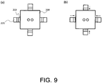
- Fig. 8 illustrates the case in which the pressing-down part 210, the transmission part 220 and the moving part 230 have the shapes shown in Figs. 5 to 7 and in which there are four transmission parts 220. More specifically, Fig. 8(a) shows a plan view, Fig. 8(b1) shows a cross-sectional view along line D-D and Fig. 8(c1) shows a bottom view. Fig. 9(a) shows a plan view where the pressing-down part 210 is removed.
- the concave part 211 of the pressing-down part 210 surrounds the four transmission parts 220 such that the first slope 212 and the second slope 221 make contact with each other on a surface-to-surface basis, and the moving part 230 is mounted on the third slopes 222 of the four transmission parts 220 that surround the moving part 230 such that the surface that is formed with the first stamp 231 faces the surface 215.
- the pressing-down part 210 and the transmission parts 220 may be coupled to each other by means of an elastic body, such as a spring, or the like, for securement of integrity and for restoration of the pressing-down part 210 to the state prior to the pressing down from the state after the pressing down (not shown).
- the moving part 230 may also be coupled to the pressing-down part 210 and/or the transmission parts 220 as appropriate.
- the detection method is employed by which the positions are detected by the touch panel 11 by causing the statically conductive object to make contact therewith, and when the transmission parts 220 are configured such that both the first stamp 231 and the second stamp 213 make contact with the surface 215, the material of the transmission parts 220 needs to be non-statically conductive.
- the detection method when the detection method is employed by which the positions are detected by the touch panel 11 being pressed down, the shape, or the like, of the respective parts needs to be designed such that the first stamp 231 and the second stamp 213 project more than the transmission parts 220 in order to prevent the transmission parts 220 from pressing down the touch panel 11 at the time of sealing the electronic stamp 200.
- the transmission parts 220 can be configured so as to make contact with the touch panel 11 along with both the first stamp 231 and the second stamp 213.
- the pressing-down part 210 when the pressing-down part 210 is not pressed down, the first stamp 231 is exposed to be ready for making contact with or for being pressed down against the touch panel 11 as shown in Fig. 8(b1) .
- the second stamp 213 when the pressing-down part 210 is pressed down toward the surface 215, the second stamp 213 lowers down and the four transmission parts 220 are pressed and move toward the central axis of the concave part 211 by the first slopes 212 sliding along the second slopes 221 as shown in Fig. 8(b2) , and thus, the area of the part surrounded by the third slopes 222 of the four transmission parts 220 decreases.
- the moving part 230 provided with the first stamp 231 rises to the upper part with a larger area by sliding along the third slopes 222, and thus, the lowered second stamp 213 is exposed to be ready for making contact with or for being pressed down against the touch panel 11 in place of the first stamp 231. Accordingly, subsequent to the plurality of members arranged in the predetermined relative positional relationship making contact with the touch panel 11, the arrangement of the plurality of members arranged in the predetermined relative positional relationship can be changed to an arrangement of another predetermined relative positional relationship in a semi-automatic and prompt manner by pressing down the pressing-down part 210.
- examples of the method of semi-automatically changing the arrangement of the members include, regarding the electronic stamp 200 shown in Fig.
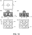
- Fig. 10 is a diagram describing the electronic stamp 201, which is a modification of the electronic stamp 200 according to the method (I). More specifically, Fig. 10(a) shows a plan view, Fig. 10(b1) shows a cross-sectional view along line E-E and Fig. 10(c1) shows a bottom view.
- the third stamp 241 made up of one or more members is provided on the bottom face of the pressing-down part 210.
- the number of members to be provided and the positions of the members to be provided are arbitrary.
- the shape of the surfaces of the respective members facing the surface 215 is also arbitrary and the example shown in Fig. 10 is circular.
- the material of the respective members configuring the third stamp 241 needs to be statically conductive if the detection method of the touch panel 11, to which the electronic stamp 201 is applied, is by means of detecting touches/contacts of a statically conductive object; however, any material may be used if such detection method is by means of detecting pressing-downs of the touch panel.
- the third stamp 241 usually is exposed in the same plane as the first stamp 231 from the bottom face of the pressing-down part 210, and the third stamp 241 is configured such that it is exposed in the same plane as the second stamp 213 from the bottom face of the pressing-down part 210, even after the pressing-down part 210 is pressed down. In other words, the third stamp is exposed to be ready for making contact with or for being pressed down against the touch panel both prior to and subsequent to the pressing down of the pressing-down part.
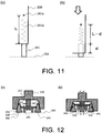
- the change in relative positions between the pressing-down part 210 and the third stamp 241 due to the pressing-down of the pressing-down part 210 is absorbed, for example, by fixing the respective members of the third stamp 241 to the pressing-down part 210 via an elastic body, such as a spring, or the like. More specifically, as shown in Fig. 11(a) , a spring fixing part 241a provided in the pressing-down part 210 and a member of the third stamp 241 are connected to each other via a spring 241b having length L, and thus, even when the pressing-down part 210 is pressed down by length d, as shown in Fig.
- the spring 241b decreases by length d and the member of the third stamp enters the pressing-down part 210 by length d to cover the decreased part. In this way, the change in the relative positions between the pressing-down part 210 and the third stamp 241 due to the pressing-down of the pressing-down part 210 is absorbed, and thus, the exposure state of the third stamp 241 can be maintained.
- Fig. 12 is a diagram describing the electronic stamp 202, which is a modification of the electronic stamp 200 according to the method (II). In this configuration, all or part of the bottom face of at least one transmission part 220 is used as the third stamp 241.
- Fig. 12 shows a cross-sectional view describing an example of the electronic stamp 202 that uses all of the bottom face of at least one transmission part 220 as the third stamp 241. More specifically, Fig. 12(a) shows a cross-sectional view prior to the pressing-down of the pressing-down part 210 and Fig. 12(b) shows a cross-sectional view subsequent to the pressing-down of the pressing-down part 210.
- the electronic stamp 202 is configured, at the time of sealing with the electronic stamp 202, such that both the transmission part 220 and the first stamp 231 are contactable to the surface 215 prior to the pressing-down of the pressing-down part 210 and such that both the transmission part 220 and the second stamp 213 are contactable to the surface 215 subsequent to the pressing-down of the pressing-down part 210.
- the transmission part 220 is to be recognized as the third stamp 241 by the touch panel 11, when the detection method of the touch panel 11, to which the electronic stamp 202 is applied, is by means of detecting touches/contacts of a statically conductive object, the material of the bottom face of the transmission part 220, i.e. the third stamp 241 needs to be statically conductive.
- any number out of the plurality of transmission parts 220 may be used as the third stamp.
- the detection method of the touch panel 11, to which the electronic stamp 202 is applied is by means of detecting touches/contacts of a statically conductive object
- the first stamp 231 and the third stamp 241 are exposed to be ready for making contact with or for being pressed down against the touch panel 11, whereas in the state where the pressing-down part is pressed down toward the surface 215, the second stamp 213 and the third stamp 241 are exposed to be ready for making contact with or for being pressed down against the touch panel 11.
- the third stamp 241 is exposed to be ready for making contact with or for being pressed down against the touch panel 11 both prior to and subsequent to the pressing down of the pressing-down part 210.
- the plurality of absolute positions on the touch panel 11, which are touched or pressed down via sealing in the predetermined relative positional relationship, and the plurality of absolute positions on the touch panel 11, which are touched or pressed down in the another predetermined relative positional relationship share at least one common position.
- the arrangement of the plurality of members arranged in the predetermined relative positional relationship can be changed semi-automatically and promptly to the arrangement in the another predetermined relative positional relationship in such a manner that the plurality of absolute positions on the touch panel 11, which are touched or pressed down in the predetermined relative positional relationship, and the plurality of absolute positions on the touch panel 11, which are touched or pressed down in the another predetermined relative positional relationship, share at least one common position.
- the content of the processes in the respective means and parts is described by a program.
- Such program may be stored on, for example, a hard disc device, and at the time of execution, the required program and data may be loaded onto a Random Access Memory (RAM).
- RAM Random Access Memory
- the respective process content is then achieved on the computer when a Central Processing Unit (CPU) thereof executes such program.
- CPU Central Processing Unit
Landscapes
- Engineering & Computer Science (AREA)
- Theoretical Computer Science (AREA)
- General Engineering & Computer Science (AREA)
- Physics & Mathematics (AREA)
- General Physics & Mathematics (AREA)
- Human Computer Interaction (AREA)
- Computer Security & Cryptography (AREA)
- Computer Hardware Design (AREA)
- Software Systems (AREA)
- User Interface Of Digital Computer (AREA)
- Position Input By Displaying (AREA)
Applications Claiming Priority (1)
| Application Number | Priority Date | Filing Date | Title |
|---|---|---|---|
| PCT/JP2015/063831 WO2016181539A1 (fr) | 2015-05-13 | 2015-05-13 | Dispositif de terminal, cachet électronique et programme |
Publications (2)
| Publication Number | Publication Date |
|---|---|
| EP3296844A1 true EP3296844A1 (fr) | 2018-03-21 |
| EP3296844A4 EP3296844A4 (fr) | 2018-12-26 |
Family
ID=57247880
Family Applications (1)
| Application Number | Title | Priority Date | Filing Date |
|---|---|---|---|
| EP15891863.1A Withdrawn EP3296844A4 (fr) | 2015-05-13 | 2015-05-13 | Dispositif de terminal, cachet électronique et programme |
Country Status (4)
| Country | Link |
|---|---|
| US (1) | US20180107296A1 (fr) |
| EP (1) | EP3296844A4 (fr) |
| JP (1) | JP6657200B2 (fr) |
| WO (1) | WO2016181539A1 (fr) |
Cited By (2)
| Publication number | Priority date | Publication date | Assignee | Title |
|---|---|---|---|---|
| EP3678081A4 (fr) * | 2017-08-30 | 2021-04-07 | Rakuten, Inc. | Système de paiement, procédé de paiement et programme |
| US11177968B2 (en) | 2020-02-19 | 2021-11-16 | International Business Machines Corporation | Roller-shaped electronic stamp |
Families Citing this family (7)
| Publication number | Priority date | Publication date | Assignee | Title |
|---|---|---|---|---|
| US20200387265A1 (en) * | 2017-06-30 | 2020-12-10 | I.P Solutions, Ltd. | Code generation device |
| TWI636355B (zh) | 2017-08-01 | 2018-09-21 | 群光電能科技股份有限公司 | 電子印章 |
| JP6613407B2 (ja) * | 2017-12-29 | 2019-12-04 | 株式会社I・Pソリューションズ | コード発生装置 |
| EP3750101A4 (fr) * | 2018-02-07 | 2021-10-06 | Crypto Lynx Ltd | Procédé, système et/ou dispositif de signature |
| CA3206929A1 (fr) * | 2021-02-05 | 2022-08-11 | Jonathan Siegel | Systeme et procede pour un dispositif de signature electronique |
| US12493363B2 (en) * | 2021-02-05 | 2025-12-09 | Jonathan SIEGEL | System and method for an electronic signature device |
| TWI816535B (zh) * | 2022-08-31 | 2023-09-21 | 合作金庫商業銀行股份有限公司 | 金融服務認證裝置 |
Family Cites Families (6)
| Publication number | Priority date | Publication date | Assignee | Title |
|---|---|---|---|---|
| MX2012010864A (es) * | 2010-03-22 | 2013-04-03 | Mattel Inc | Dispositivo electronico y la entrada y salida de datos. |
| JP2013012057A (ja) * | 2011-06-29 | 2013-01-17 | Panasonic Corp | 認証鍵及び認証装置 |
| KR101305412B1 (ko) * | 2012-01-09 | 2013-09-06 | 최영우 | 터치스크린이 채용된 휴대 단말기용 터치스탬프 및 이를 이용한 인증시스템 및 방법 |
| US20140043264A1 (en) * | 2012-08-07 | 2014-02-13 | SnowShoeFood, LLC. | Touchscreen authentication unit with dynamic touch locations |
| JP2014228997A (ja) * | 2013-05-21 | 2014-12-08 | 凸版印刷株式会社 | 携帯端末装置及びその認証方法 |
| DE202013008053U1 (de) * | 2013-09-12 | 2014-02-20 | Florian Hackenberger | Digitaler Stempel für Authentifizierungsvorgänge auf Endgeräten mit Touchscreen |
-
2015
- 2015-05-13 EP EP15891863.1A patent/EP3296844A4/fr not_active Withdrawn
- 2015-05-13 WO PCT/JP2015/063831 patent/WO2016181539A1/fr not_active Ceased
- 2015-05-13 US US15/573,120 patent/US20180107296A1/en not_active Abandoned
- 2015-05-13 JP JP2017517553A patent/JP6657200B2/ja active Active
Cited By (2)
| Publication number | Priority date | Publication date | Assignee | Title |
|---|---|---|---|---|
| EP3678081A4 (fr) * | 2017-08-30 | 2021-04-07 | Rakuten, Inc. | Système de paiement, procédé de paiement et programme |
| US11177968B2 (en) | 2020-02-19 | 2021-11-16 | International Business Machines Corporation | Roller-shaped electronic stamp |
Also Published As
| Publication number | Publication date |
|---|---|
| JP6657200B2 (ja) | 2020-03-04 |
| WO2016181539A1 (fr) | 2016-11-17 |
| US20180107296A1 (en) | 2018-04-19 |
| EP3296844A4 (fr) | 2018-12-26 |
| JPWO2016181539A1 (ja) | 2018-03-29 |
Similar Documents
| Publication | Publication Date | Title |
|---|---|---|
| EP3296844A1 (fr) | Dispositif de terminal, cachet électronique et programme | |
| US9514297B2 (en) | Systems and methods for gesture lock obfuscation | |
| EP3312752B1 (fr) | Dispositif électronique et procédé d'acquisition d'informations d'empreintes digitales | |
| US8949974B2 (en) | Mobile device with password protected desktop screen | |
| ES2881964T3 (es) | Método y dispositivo de reconocimiento de huellas dactilares, terminal móvil y medio de almacenamiento | |
| CN107608615B (zh) | 指纹识别功能开启方法、装置、终端和存储介质 | |
| KR102355039B1 (ko) | 잠금 화면 출력 제어 방법 및 이를 지원하는 전자 장치 | |
| US20150356286A1 (en) | Continuous monitoring of fingerprint signature on a mobile touchscreen for identity management | |
| CN105335641B (zh) | 一种基于指纹识别的身份验证方法及装置 | |
| US20140270415A1 (en) | Sensing characteristics of adjacent fingers for user authentication | |
| EP3488372B1 (fr) | Procédé de protection d'informations personnelles et dispositif électronique associé | |
| CN103324964B (zh) | 身份辨识系统及方法 | |
| CN107340960A (zh) | 用户界面控制方法及系统 | |
| KR20170094895A (ko) | 지문을 인식하기 위한 방법 및 전자 장치 | |
| US9122390B2 (en) | Method, application and/or service to collect more fine-grained or extra event data from a user sensor device | |
| US10638316B2 (en) | Wearable computer apparatus with same hand user authentication | |
| US20130305240A1 (en) | Installing applications to password protected desktop screens on a mobile device | |
| CN111079119B (zh) | 验证方法、装置、设备及存储介质 | |
| CN105447373B (zh) | 密码验证方法及装置 | |
| US10237736B2 (en) | Unlocking of a mobile device by a code received via a stencil on a touchscreen | |
| CN105376365B (zh) | 一种手机 | |
| JP6783404B2 (ja) | 電子印章 | |
| CN209746564U (zh) | 大面积指纹传感器 | |
| KR20140035758A (ko) | 지문을 이용한 애플리케이션 사용 제한 방법, 사용자 단말기 및 기록 매체 | |
| CN107529635A (zh) | 终端控制方法、装置、电子设备及存储介质 |
Legal Events
| Date | Code | Title | Description |
|---|---|---|---|
| STAA | Information on the status of an ep patent application or granted ep patent |
Free format text: STATUS: THE INTERNATIONAL PUBLICATION HAS BEEN MADE |
|
| PUAI | Public reference made under article 153(3) epc to a published international application that has entered the european phase |
Free format text: ORIGINAL CODE: 0009012 |
|
| STAA | Information on the status of an ep patent application or granted ep patent |
Free format text: STATUS: REQUEST FOR EXAMINATION WAS MADE |
|
| 17P | Request for examination filed |
Effective date: 20171123 |
|
| AK | Designated contracting states |
Kind code of ref document: A1 Designated state(s): AL AT BE BG CH CY CZ DE DK EE ES FI FR GB GR HR HU IE IS IT LI LT LU LV MC MK MT NL NO PL PT RO RS SE SI SK SM TR |
|
| AX | Request for extension of the european patent |
Extension state: BA ME |
|
| RAP1 | Party data changed (applicant data changed or rights of an application transferred) |
Owner name: TRANSCOSMOS INC. Owner name: PLAYGROUND CO., LTD. |
|
| RAP1 | Party data changed (applicant data changed or rights of an application transferred) |
Owner name: PLAYGROUND CO., LTD. |
|
| DAV | Request for validation of the european patent (deleted) | ||
| DAX | Request for extension of the european patent (deleted) | ||
| A4 | Supplementary search report drawn up and despatched |
Effective date: 20181122 |
|
| RIC1 | Information provided on ipc code assigned before grant |
Ipc: G06F 3/0488 20130101ALI20181116BHEP Ipc: G06F 3/03 20060101AFI20181116BHEP Ipc: G06F 3/041 20060101ALI20181116BHEP Ipc: G06F 21/31 20130101ALI20181116BHEP |
|
| STAA | Information on the status of an ep patent application or granted ep patent |
Free format text: STATUS: THE APPLICATION HAS BEEN WITHDRAWN |
|
| 18W | Application withdrawn |
Effective date: 20210426 |