EP3297057B1 - Procédé pour sceller une partie d'étanchéité d`un boitier de batterie - Google Patents
Procédé pour sceller une partie d'étanchéité d`un boitier de batterie Download PDFInfo
- Publication number
- EP3297057B1 EP3297057B1 EP16866546.1A EP16866546A EP3297057B1 EP 3297057 B1 EP3297057 B1 EP 3297057B1 EP 16866546 A EP16866546 A EP 16866546A EP 3297057 B1 EP3297057 B1 EP 3297057B1
- Authority
- EP
- European Patent Office
- Prior art keywords
- sealing part
- electrode lead
- heat dissipation
- dissipation piece
- sealing
- Prior art date
- Legal status (The legal status is an assumption and is not a legal conclusion. Google has not performed a legal analysis and makes no representation as to the accuracy of the status listed.)
- Active
Links
Images



Classifications
-
- H—ELECTRICITY
- H01—ELECTRIC ELEMENTS
- H01M—PROCESSES OR MEANS, e.g. BATTERIES, FOR THE DIRECT CONVERSION OF CHEMICAL ENERGY INTO ELECTRICAL ENERGY
- H01M50/00—Constructional details or processes of manufacture of the non-active parts of electrochemical cells other than fuel cells, e.g. hybrid cells
- H01M50/10—Primary casings; Jackets or wrappings
- H01M50/172—Arrangements of electric connectors penetrating the casing
-
- H—ELECTRICITY
- H01—ELECTRIC ELEMENTS
- H01M—PROCESSES OR MEANS, e.g. BATTERIES, FOR THE DIRECT CONVERSION OF CHEMICAL ENERGY INTO ELECTRICAL ENERGY
- H01M10/00—Secondary cells; Manufacture thereof
- H01M10/60—Heating or cooling; Temperature control
- H01M10/65—Means for temperature control structurally associated with the cells
- H01M10/655—Solid structures for heat exchange or heat conduction
- H01M10/6551—Surfaces specially adapted for heat dissipation or radiation, e.g. fins or coatings
-
- H—ELECTRICITY
- H01—ELECTRIC ELEMENTS
- H01M—PROCESSES OR MEANS, e.g. BATTERIES, FOR THE DIRECT CONVERSION OF CHEMICAL ENERGY INTO ELECTRICAL ENERGY
- H01M10/00—Secondary cells; Manufacture thereof
- H01M10/04—Construction or manufacture in general
- H01M10/0404—Machines for assembling batteries
-
- H—ELECTRICITY
- H01—ELECTRIC ELEMENTS
- H01M—PROCESSES OR MEANS, e.g. BATTERIES, FOR THE DIRECT CONVERSION OF CHEMICAL ENERGY INTO ELECTRICAL ENERGY
- H01M50/00—Constructional details or processes of manufacture of the non-active parts of electrochemical cells other than fuel cells, e.g. hybrid cells
- H01M50/10—Primary casings; Jackets or wrappings
- H01M50/172—Arrangements of electric connectors penetrating the casing
- H01M50/174—Arrangements of electric connectors penetrating the casing adapted for the shape of the cells
- H01M50/178—Arrangements of electric connectors penetrating the casing adapted for the shape of the cells for pouch or flexible bag cells
-
- H—ELECTRICITY
- H01—ELECTRIC ELEMENTS
- H01M—PROCESSES OR MEANS, e.g. BATTERIES, FOR THE DIRECT CONVERSION OF CHEMICAL ENERGY INTO ELECTRICAL ENERGY
- H01M50/00—Constructional details or processes of manufacture of the non-active parts of electrochemical cells other than fuel cells, e.g. hybrid cells
- H01M50/10—Primary casings; Jackets or wrappings
- H01M50/183—Sealing members
- H01M50/186—Sealing members characterised by the disposition of the sealing members
-
- H—ELECTRICITY
- H01—ELECTRIC ELEMENTS
- H01M—PROCESSES OR MEANS, e.g. BATTERIES, FOR THE DIRECT CONVERSION OF CHEMICAL ENERGY INTO ELECTRICAL ENERGY
- H01M50/00—Constructional details or processes of manufacture of the non-active parts of electrochemical cells other than fuel cells, e.g. hybrid cells
- H01M50/50—Current conducting connections for cells or batteries
- H01M50/531—Electrode connections inside a battery casing
-
- Y—GENERAL TAGGING OF NEW TECHNOLOGICAL DEVELOPMENTS; GENERAL TAGGING OF CROSS-SECTIONAL TECHNOLOGIES SPANNING OVER SEVERAL SECTIONS OF THE IPC; TECHNICAL SUBJECTS COVERED BY FORMER USPC CROSS-REFERENCE ART COLLECTIONS [XRACs] AND DIGESTS
- Y02—TECHNOLOGIES OR APPLICATIONS FOR MITIGATION OR ADAPTATION AGAINST CLIMATE CHANGE
- Y02E—REDUCTION OF GREENHOUSE GAS [GHG] EMISSIONS, RELATED TO ENERGY GENERATION, TRANSMISSION OR DISTRIBUTION
- Y02E60/00—Enabling technologies; Technologies with a potential or indirect contribution to GHG emissions mitigation
- Y02E60/10—Energy storage using batteries
-
- Y—GENERAL TAGGING OF NEW TECHNOLOGICAL DEVELOPMENTS; GENERAL TAGGING OF CROSS-SECTIONAL TECHNOLOGIES SPANNING OVER SEVERAL SECTIONS OF THE IPC; TECHNICAL SUBJECTS COVERED BY FORMER USPC CROSS-REFERENCE ART COLLECTIONS [XRACs] AND DIGESTS
- Y02—TECHNOLOGIES OR APPLICATIONS FOR MITIGATION OR ADAPTATION AGAINST CLIMATE CHANGE
- Y02P—CLIMATE CHANGE MITIGATION TECHNOLOGIES IN THE PRODUCTION OR PROCESSING OF GOODS
- Y02P70/00—Climate change mitigation technologies in the production process for final industrial or consumer products
- Y02P70/50—Manufacturing or production processes characterised by the final manufactured product
Definitions
- the present invention relates to a sealing apparatus for a secondary battery, and more particularly, to a sealing apparatus for a secondary battery, which improves sealability with respect to a sealing part of a battery case at which an electrode lead is disposed.
- secondary batteries refer to chargeable and dischargeable batteries, unlike primary batteries that are not chargeable.
- Such a secondary battery is being widely used in the high-tech electronic fields such as mobile phones, notebook computers, and camcorders.
- JP2008-146942 discloses the manufacturing method and device for the thin type battery.
- a secondary battery comprises an electrode assembly provided with an electrode tab, an electrode lead coupled to the electrode tab of the electrode assembly, a battery case accommodating the electrode assembly in a state in which a end of the electrode lead is exposed to the outside, and a lead film surrounding the electrode lead disposed on a sealing part of the battery case.
- the sealing part at which the electrode lead is disposed when the sealing part at which the electrode lead is disposed is thermally fused, a heat source may not be released to the outside to cause oversealing of the sealing part.
- the sealing part may be oversealed to damage an insulation film, thereby causing insulation failures.
- an object of the present invention is to provide a sealing apparatus in which a heat source generated in a sealing part is released to the outside through an electrode lead when the sealing part at which the electrode lead is disposed is thermally fused, to prevent oversealing of the sealing part and insulation failures from occurring.
- a method for sealing a sealing part of a battery case at which an electrode lead coupled to an electrode assembly is disposed, by using a sealing apparatus comprising a thermal fusion member and a temperature rising prevention member comprises applying heat and a pressure to the sealing part of the battery case by using the thermal fusion member to seal the sealing part of the battery case, and cooling an end of the electrode lead exposed to an outside of the battery case by using the temperature rising prevention member to cool the sealing part through the electrode lead, thereby preventing the sealing part from increasing in temperature.
- the temperature rising prevention member may release heat of the sealing part to the outside through the electrode lead to cool the sealing part.
- the temperature rising prevention member cools the sealing part by cooling the electrode lead.
- the temperature rising prevention member supports the end of the electrode lead at a temperature less than that of the thermal fusion member.
- the temperature rising prevention member is provided with a first heat dissipation piece and a second heat dissipation piece, which respectively support both side surfaces of the end of the electrode lead.
- the first heat dissipation piece has a temperature less than that of the thermal fusion member, and the second heat dissipation piece has a temperature less than that of the first heat dissipation piece.
- the first heat dissipation piece supports one side surface of the end of the electrode lead, and after a preset time elapses, the second heat dissipation piece supports the other side surface of the end of the electrode lead.
- the preset time may range of 1 second to 5 seconds.
- the temperature rising prevention member may further support the end of the electrode lead for 1 second to 5 seconds after the thermal fusion member is separated from the sealing part.
- the thermal fusion member may be separated from the sealing part, and simultaneously, the second heat dissipation piece may be separated from the end of the electrode lead, wherein the first heat dissipation piece may further support the end of the electrode lead for 1 second to 5 seconds to cool the sealing part.
- the present invention has effects as follows.
- the sealing apparatus for the secondary battery comprises the temperature rising prevention member supported on the electrode lead to cool the sealing part through the electrode lead and thereby to prevent the sealing part from increasing in temperature, thereby preventing the oversealing of the sealing part and the insulation failures from occurring.
- the temperature rising prevention member according to the present invention may release the heat of the sealing part to the outside through the electrode lead to effectively cool the sealing part.
- the temperature rising prevention member according to the present invention may effectively cool the sealing part by cooling the electrode lead.
- the temperature rising prevention member according to the present invention may be provided with the first heat dissipation piece and the second heat dissipation piece, which are different from each other, to more effectively release the heat generated in the sealing part.
- the first heat dissipation piece may be supported on the electrode lead to release the low-temperature heat generated during the initial thermal fusion to the outside, and then, the second heat dissipation piece having a temperature less than that of the first heat dissipation piece may be supported on the electrode lead to release the high-temperature heat after the sealing part is thermally fused to the outside.
- the temperature rising prevention member according to the present invention may be supported on the electrode lead even after the sealing part is thermally fused to cool the sealing part, thereby preventing the oversealing of the sealing part due to the heat remaining in the sealing part and the insulation failures from occurring.
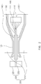
- a secondary battery according to an embodiment of the present invention comprises an electrode assembly 110 provided with an electrode tab 111, an electrode lead 130 coupled to the electrode tab 111 of the electrode assembly 110, a battery case 120 accommodating the electrode assembly 110 in a state in which a end of the electrode lead 130 is exposed to the outside, and a lead film 140 surrounding disposed on a sealing part 121 of the battery case 120.
- the sealing part 121 is sealed to be airtight in a state in which the electrode assembly 110 is accommodated in the battery case 120.
- a sealing apparatus 200 is used for sealing the sealing part 121.
- the sealing apparatus 200 for the secondary battery comprises a thermal fusion member 210 sealing the sealing part 121 and a temperature rising prevention member 220 cooling heat generated in the sealing part 121 through the electrode lead 130 to prevent the sealing part 121 from increasing in temperature.
- the thermal fusion member 210 comprises an upper sealing part and a lower sealing part, which apply heat and a pressure to top and bottom surfaces of the sealing part 121 at the same time to seal the sealing part 121.
- the thermal fusion member 210 thermally fuses and seals the sealing part 121 of the battery case 120 at which the electrode lead 130 is disposed.
- the sealing part 121 may be oversealed. Particularly, when an insulation film attached to an inner surface of the sealing part 121 is damaged, insulation failures may occur.
- the temperature rising prevention member 220 cooling the sealing part 121 of the battery case 120 through the electrode lead 130 is provided.
- the temperature rising prevention member 220 may release the heat of the sealing part 121 to the outside through the electrode lead 130 to cool the sealing part 121.
- the sealing part 121 may be prevented from increasing in temperature and being oversealed.
- the temperature rising prevention member 220 supports a end of the electrode lead 130 at a temperature less than that of heat generated in the thermal fusion member 210. That is, the temperature rising prevention member 220 has a temperature less than that of the heat generated in the sealing part 121 that is thermally fused by the thermal fusion member 210.
- the heat generated in the sealing part 121 is stably released through the electrode lead 130.
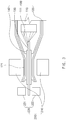
- the temperature rising prevention member 220 is provided with a first heat dissipation piece 221 and a second heat dissipation piece 222 to respectively support both side surfaces of the end of the electrode lead 130. That is, the first heat dissipation piece 221 supports one side surface (a right top surface when viewed in FIG. 2 ) of the end of the electrode lead 130, and the second heat dissipation piece 222 supports the other side surface (a right bottom surface when viewed in FIG. 2 ) of the end of the electrode lead 130.
- the heat of the sealing part 121 disposed above and below the electrode lead 130 may be uniformly absorbed and then released to the outside to improve sealability of the sealing part 121.
- the first heat dissipation piece 221 and the second heat dissipation piece 222 may have the same temperature or temperatures different from each other. That is, the first heat dissipation piece 221 may have a temperature less than that of the heat generated in the thermal fusion member 210, and the second heat dissipation piece 222 may have a temperature less than that of the first heat dissipation piece 221.
- the first heat dissipation piece 221 having the temperature less than that of the heat generated in the thermal fusion member 210 may be supported on the electrode lead 130 at an initial period of the thermal fusion of the sealing part 121 through the thermal fusion member 210 to minimize the releasing of the heat generated in the sealing part 121. That is, when the heat of the sealing part 121 is excessively released at the initial period of the thermal fusion, the sealability may be deteriorated. Thus, the releasing of the heat of the sealing part 121 has to be minimized.
- first heat dissipation piece 221 and the second heat dissipation piece 222 are supported on the electrode lead 130 at a middle period of the thermal fusion of the sealing part 121 through the thermal fusion member 210, and thus, high-temperature heat generated in the sealing part 121 may be quickly released to the outside through the first heat dissipation piece 221 and the second heat dissipation piece 222 to prevent the sealing part 121 from being oversealed.
- the second heat dissipation piece 222 has a temperature less than that of the first heat dissipation piece 221, the heat generated in the sealing part 121 may be more quickly released to the outside.
- the first heat dissipation piece 221 is supported on one side surface of the end of the electrode lead 130 at the same time at which the thermal fusion member 210 thermally fuses the sealing part 121.
- the second heat dissipation piece 222 is supported on the other side surface of the end of the electrode lead 130 to more improve the sealability of the sealing part 121.
- the preset time may be 1 second to 5 seconds, particularly, 3 seconds. That is, the thermal fusion member 210 presses the sealing part 121 in a state of being heated.
- the heat may be released in a state in which the sealing part 121 is not sealed to cause sealing failures.
- the sealing part 121 may be oversealed to cause failures.
- the second heat dissipation piece 222 is supported on the electrode lead 130 within 1 second to 5 seconds after the second heat dissipation piece 222 supports the electrode lead 130 to improve the sealability of the sealing part 121 and prevent the sealing part 121 from being oversealed.
- the temperature rising prevention member 220 further supports the end of the electrode lead 130 for 1 second to 5 seconds to release heat even though the thermal fusion is completed, and the thermal fusion member 210 is separated from the sealing part 121. That is, although the thermal fusion is completed, the heat remains in the sealing part 121. Thus, the temperature rising prevention member 220 may completely release the heat remaining in the sealing part 121 to the outside, thereby improving the sealability.
- the sealing part 121 may be rapidly solidified to cause the sealing failures.
- the second heat dissipation piece 222 is separated first from the electrode lead 130, and then, the first heat dissipation piece 221 is separated from the electrode lead 130 after the preset time elaspes so that the sealing part 121 is slowly solidified.
- the thermal fusion member 210 is separated from the sealing part 121, and simultaneously, the second heat dissipation piece 222 is separated from the end of the electrode lead 130.
- the first dissipation piece 221 further supports the end of the electrode lead 130 for 1 second to 5 seconds to prevent the heat remaining in the sealing part 121 from being excessively released, thereby inducing the slow solidification of the sealing part 121.
- the sealing apparatus for the secondary battery comprising the above-described constituents according to the present invention may prevent the sealing part of the battery case, in which the electrode lead is provided, from being oversealed and prevent the insulation failures from occurring.
- the thermal fusion member 210 is disposed on the sealing part 121 of the battery case 120 in which the electrode lead 130 is provided.
- the temperature rising prevention member 220 is disposed on the end of the electrode lead 130. That is, the temperature rising prevention member 220 is provided with the first heat dissipation piece 221 and the second heat dissipation piece 222, which are respectively disposed on the top and bottom surfaces of the electrode lead 130.
- the first heat dissipation piece has a temperature less than that of heat generated in the thermal fusion member 210
- the second heat dissipation piece 222 has a temperature less than that of the first heat dissipation piece 221.
- the second heat dissipation piece 222 may have a temperature equal to or less than room temperature.
- the sealing part 121 is thermally fused and sealed by the thermal fusion member 210, and simultaneously, the first heat dissipation piece 221 of the temperature rising prevention member 220 is supported on the top surface of the electrode lead 121 to release heat generated in the sealing part 121 to the outside through the electrode lead 121 and the first heat dissipation piece 221, thereby cooling the sealing part 121.
- the thermal fusion member 210 thermally fuses the sealing part 121, and then, 3 seconds elaspes, the second heat dissipation piece 222 is supported on the bottom surface of the electrode lead 121.
- the high-temperature heat generated in the sealing part 121 is quickly released to the outside through the electrode lead 121 and the second heat dissipation piece 222 to cool the sealing part 121, thereby preventing the sealing part 121 from being oversealed.
- the thermal fusion member 210 is separated from the sealing part 121, and simultaneously, the second heat dissipation piece 222 is separated from the electrode lead 130.
- the first heat dissipation piece 221 further releases the heat generated in the sealing part 121 for 1 second to 5 seconds.
- the sealing part 121 is quickly solidified to deteriorate the sealability.
- the heat generated in the sealing part 121 is released to the outside through the first heat dissipation piece 221.
- the sealing apparatus 200 for the secondary battery may prevent the sealing part of the battery case, in which the electrode lead is provided, from being oversealed and prevent the insulation failures from occurring.
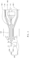
- a temperature rising prevention member 220' of a sealing apparatus 200' for a secondary battery may be a cooling device that cools a sealing part 121 by cooling an electrode lead 130.
- the cooling device may be largely classified into air-cooling type and water-cooling type according to a structure thereof.
- the temperature rising prevention member 220' may directly cool the electrode lead 130 to more effectively reduce a temperature of the sealing part 121 disposed on the electrode lead 130, particularly, to more precisely and uniformly adjust a cooling temperature of the sealing part 121.
- the sealing apparatus 200' for the secondary battery may comprise the temperature rising prevention member 220' that cools the sealing part 121 by cooling the electrode lead 130 to improve sealability and effectively prevent the sealing part 121 from being oversealed.
Landscapes
- Chemical & Material Sciences (AREA)
- Chemical Kinetics & Catalysis (AREA)
- Electrochemistry (AREA)
- General Chemical & Material Sciences (AREA)
- Engineering & Computer Science (AREA)
- Manufacturing & Machinery (AREA)
- Sealing Battery Cases Or Jackets (AREA)
- Secondary Cells (AREA)
- Connection Of Batteries Or Terminals (AREA)
Claims (5)
- Procédé pour étanchéifier une partie d'étanchéité (121) d'un boîtier de batterie (120) au niveau duquel un fil d'électrode couplé à un ensemble électrode est disposé, en utilisant un appareil d'étanchéité (200) comprenant un élément de fusion thermique (210) et un élément de prévention de hausse de température (220), le procédé comprenant :l'application de chaleur et d'une pression à la partie d'étanchéité (121) du boîtier de batterie (120) en utilisant l'élément de fusion thermique (210) pour étanchéifier la partie d'étanchéité (121) du boîtier de batterie (120) ; etle refroidissement d'une extrémité du fil d'électrode (130) exposée à un extérieur du boîtier de batterie en utilisant l'élément de prévention de hausse de température (220) pour refroidir la partie d'étanchéité (121) à travers le fil d'électrode (130), empêchant ainsi la partie d'étanchéité d'augmenter en température,dans lequel l'élément de prévention de hausse de température (220) est pourvu d'une première pièce de dissipation de chaleur (221) et d'une seconde pièce de dissipation de chaleur (222), qui supportent respectivement des surfaces latérales de l'extrémité du fil d'électrode (130),dans lequel la première pièce de dissipation de chaleur (221) a une température inférieure à celle de l'élément de fusion thermique (210), et la seconde pièce de dissipation de chaleur (222) a une température inférieure à celle de la première pièce de dissipation de chaleur (221), etdans lequel la première pièce de dissipation de chaleur (221) supporte une surface latérale de l'extrémité du fil d'électrode (130), et après qu'un temps prédéfini s'est écoulé, la seconde pièce de dissipation de chaleur (222) supporte l'autre surface latérale de l'extrémité du fil d'électrode (130).
- Procédé selon la revendication 1, dans lequel l'élément de prévention de hausse de température (220) libère de la chaleur de la partie d'étanchéité (121) vers l'extérieur à travers le fil d'électrode (130) pour refroidir la partie d'étanchéité (121).
- Procédé selon la revendication 1, dans lequel le temps prédéfini va de 1 seconde à 5 secondes.
- Procédé selon la revendication 1, dans lequel l'élément de prévention de hausse de température (220) supporte en outre l'extrémité du fil d'électrode (130) pendant 1 seconde à 5 secondes après la séparation de l'élément de fusion thermique (210) de la partie d'étanchéité (121).
- Procédé selon la revendication 1, dans lequel l'élément de fusion thermique (210) est séparé de la partie d'étanchéité (121), et simultanément, la seconde pièce de dissipation de chaleur (222) est séparée de l'extrémité du fil d'électrode (130), dans lequel la première pièce de dissipation de chaleur (221) supporte en outre l'extrémité du fil d'électrode (130) pendant 1 seconde à 5 secondes pour refroidir la partie d'étanchéité (121).
Priority Applications (1)
| Application Number | Priority Date | Filing Date | Title |
|---|---|---|---|
| PL16866546T PL3297057T3 (pl) | 2015-11-18 | 2016-09-29 | Sposób uszczelniania części uszczelniającej obudowy baterii |
Applications Claiming Priority (3)
| Application Number | Priority Date | Filing Date | Title |
|---|---|---|---|
| KR20150162044 | 2015-11-18 | ||
| KR1020160122460A KR101925090B1 (ko) | 2015-11-18 | 2016-09-23 | 이차전지용 실링장치 |
| PCT/KR2016/010936 WO2017086593A1 (fr) | 2015-11-18 | 2016-09-29 | Dispositif d'étanchéité pour batterie secondaire |
Publications (3)
| Publication Number | Publication Date |
|---|---|
| EP3297057A1 EP3297057A1 (fr) | 2018-03-21 |
| EP3297057A4 EP3297057A4 (fr) | 2018-03-21 |
| EP3297057B1 true EP3297057B1 (fr) | 2019-11-06 |
Family
ID=59052166
Family Applications (1)
| Application Number | Title | Priority Date | Filing Date |
|---|---|---|---|
| EP16866546.1A Active EP3297057B1 (fr) | 2015-11-18 | 2016-09-29 | Procédé pour sceller une partie d'étanchéité d`un boitier de batterie |
Country Status (6)
| Country | Link |
|---|---|
| US (1) | US10559785B2 (fr) |
| EP (1) | EP3297057B1 (fr) |
| JP (1) | JP6618608B2 (fr) |
| KR (1) | KR101925090B1 (fr) |
| CN (1) | CN108292718B (fr) |
| PL (1) | PL3297057T3 (fr) |
Cited By (1)
| Publication number | Priority date | Publication date | Assignee | Title |
|---|---|---|---|---|
| EP4178013A4 (fr) * | 2020-09-07 | 2024-08-07 | LG Energy Solution, Ltd. | Batterie secondaire, dispositif et procédé de fabrication de fabrication de batterie secondaire |
Families Citing this family (6)
| Publication number | Priority date | Publication date | Assignee | Title |
|---|---|---|---|---|
| KR102223722B1 (ko) * | 2017-10-24 | 2021-03-05 | 주식회사 엘지화학 | 이차전지용 라미네이션 장치 및 방법 |
| JP6996421B2 (ja) | 2018-05-28 | 2022-02-21 | 大日本印刷株式会社 | 電池、ヒートシール装置、及び電池の製造方法 |
| KR102843785B1 (ko) | 2020-08-11 | 2025-08-07 | 주식회사 엘지에너지솔루션 | 이차전지용 실링장치 |
| KR102796174B1 (ko) * | 2020-09-07 | 2025-04-16 | 주식회사 엘지에너지솔루션 | 이차전지, 이차전지 제조장치 및 제조방법 |
| JP2025539548A (ja) * | 2022-12-12 | 2025-12-05 | エルジー エナジー ソリューション リミテッド | 加熱部位をターゲティングすることのできるパウチシール装置 |
| KR20250025066A (ko) * | 2023-08-14 | 2025-02-21 | 주식회사 엘지에너지솔루션 | 파우치 실링 장치 및 파우치 실링 방법 |
Family Cites Families (16)
| Publication number | Priority date | Publication date | Assignee | Title |
|---|---|---|---|---|
| JPH01213955A (ja) * | 1988-02-22 | 1989-08-28 | Toshiba Battery Co Ltd | 扁平形電池の製造方法 |
| CN1280155C (zh) | 2000-01-26 | 2006-10-18 | 大日本印刷株式会社 | 热封接方法 |
| KR100958649B1 (ko) | 2002-12-27 | 2010-05-20 | 삼성에스디아이 주식회사 | 전지부와, 이의 감는 방법과, 이를 채용하여 제조된 리튬이차 전지 |
| JP4605389B2 (ja) * | 2003-07-31 | 2011-01-05 | 日本電気株式会社 | リチウムイオン二次電池 |
| EP1667251B1 (fr) | 2003-08-08 | 2011-05-04 | NEC Corporation | Pile recouverte d'un film et procede de fabrication de cette pile |
| JP4453454B2 (ja) * | 2004-06-16 | 2010-04-21 | トヨタ自動車株式会社 | ラミネート型二次電池の製造方法及び製造装置 |
| JP5028986B2 (ja) * | 2006-12-07 | 2012-09-19 | 日産自動車株式会社 | 薄型電池、薄型電池の製造方法および製造装置 |
| JP2009272161A (ja) * | 2008-05-08 | 2009-11-19 | Toyota Motor Corp | ラミネート型電池、組電池、車両 |
| KR20120126932A (ko) * | 2011-05-13 | 2012-11-21 | 에스케이이노베이션 주식회사 | 파우치형 이차전지의 실링방법 및 실링장치 |
| KR101560217B1 (ko) | 2012-09-19 | 2015-10-15 | 주식회사 엘지화학 | 냉각 효율이 향상된 전지모듈 |
| KR101669118B1 (ko) | 2013-01-03 | 2016-10-25 | 삼성에스디아이 주식회사 | 배터리 팩 |
| KR20140090335A (ko) | 2013-01-07 | 2014-07-17 | 에스케이이노베이션 주식회사 | 자립능력을 갖는 파우치형 이차전지용 방열지지부재 및 이를 갖는 파우치형 이차전지 |
| WO2015012195A1 (fr) * | 2013-07-22 | 2015-01-29 | 株式会社村田製作所 | Procédé de fabrication de dispositif de stockage électrique stratifié |
| KR101516948B1 (ko) | 2013-10-18 | 2015-05-04 | (주)글로벌텍 | 배터리용 전극리드와 필름을 융착하는 융착 장치 |
| JP6318577B2 (ja) * | 2013-11-25 | 2018-05-09 | 日産自動車株式会社 | シール部品の製造装置及び製造方法 |
| KR20150071918A (ko) * | 2013-12-19 | 2015-06-29 | 주식회사 엘지화학 | 이차전지의 실링장치 및 실링방법 |
-
2016
- 2016-09-23 KR KR1020160122460A patent/KR101925090B1/ko active Active
- 2016-09-29 EP EP16866546.1A patent/EP3297057B1/fr active Active
- 2016-09-29 JP JP2018504189A patent/JP6618608B2/ja active Active
- 2016-09-29 US US15/736,475 patent/US10559785B2/en active Active
- 2016-09-29 PL PL16866546T patent/PL3297057T3/pl unknown
- 2016-09-29 CN CN201680037933.5A patent/CN108292718B/zh active Active
Non-Patent Citations (1)
| Title |
|---|
| None * |
Cited By (1)
| Publication number | Priority date | Publication date | Assignee | Title |
|---|---|---|---|---|
| EP4178013A4 (fr) * | 2020-09-07 | 2024-08-07 | LG Energy Solution, Ltd. | Batterie secondaire, dispositif et procédé de fabrication de fabrication de batterie secondaire |
Also Published As
| Publication number | Publication date |
|---|---|
| CN108292718A (zh) | 2018-07-17 |
| KR101925090B1 (ko) | 2018-12-04 |
| US10559785B2 (en) | 2020-02-11 |
| EP3297057A1 (fr) | 2018-03-21 |
| US20180190951A1 (en) | 2018-07-05 |
| JP6618608B2 (ja) | 2019-12-11 |
| CN108292718B (zh) | 2020-11-20 |
| JP2018526771A (ja) | 2018-09-13 |
| EP3297057A4 (fr) | 2018-03-21 |
| PL3297057T3 (pl) | 2020-07-13 |
| KR20170058262A (ko) | 2017-05-26 |
Similar Documents
| Publication | Publication Date | Title |
|---|---|---|
| EP3297057B1 (fr) | Procédé pour sceller une partie d'étanchéité d`un boitier de batterie | |
| EP3264488B1 (fr) | Dispositif de scellage d'une batterie secondaire | |
| CN210926140U (zh) | 一种高安全性锂离子电池 | |
| US20180320937A1 (en) | Tec heat dissipation assembly and projection device | |
| KR20160019259A (ko) | 파우치형 이차 전지의 실링 장치 | |
| KR20140102610A (ko) | 전지셀 어셈블리 및 전지셀 어셈블리의 제조방법 | |
| JP2003308815A (ja) | 電池パックとその製造方法 | |
| JP7309997B2 (ja) | 電池モジュール | |
| JP2014517458A (ja) | パウチ型二次電池のシール方法およびシール装置 | |
| WO2019036002A3 (fr) | Optimisation de bloc-batterie pour gestion thermique | |
| KR20150050319A (ko) | 커브드 이차 전지의 제조 방법 | |
| CN116801595A (zh) | 一种导热材料及其制备方法与应用 | |
| KR20140090335A (ko) | 자립능력을 갖는 파우치형 이차전지용 방열지지부재 및 이를 갖는 파우치형 이차전지 | |
| US10749152B2 (en) | Sealing apparatus for secondary battery | |
| JP2013166287A (ja) | 熱融着装置及び熱融着方法 | |
| CN104247451A (zh) | 无线通信系统中的基站 | |
| CN211743352U (zh) | 隔热板、电池模组以及电池包 | |
| KR102192993B1 (ko) | 이차전지용 파우치 및 이를 포함하는 이차전지 | |
| TWI631307B (zh) | Flat heat pipe circuit | |
| WO2017086593A1 (fr) | Dispositif d'étanchéité pour batterie secondaire | |
| KR20150067611A (ko) | 나트륨 2차 전지용 전지 모듈 | |
| WO2017034380A1 (fr) | Dispositif de scellage d'une batterie secondaire | |
| CN110289241A (zh) | 静电卡盘及其制作方法、工艺腔室和半导体处理设备 | |
| KR20180047867A (ko) | 화상방지용 쿨링 커버 | |
| JP2014164859A (ja) | 電池ユニット |
Legal Events
| Date | Code | Title | Description |
|---|---|---|---|
| STAA | Information on the status of an ep patent application or granted ep patent |
Free format text: STATUS: THE INTERNATIONAL PUBLICATION HAS BEEN MADE |
|
| PUAI | Public reference made under article 153(3) epc to a published international application that has entered the european phase |
Free format text: ORIGINAL CODE: 0009012 |
|
| STAA | Information on the status of an ep patent application or granted ep patent |
Free format text: STATUS: REQUEST FOR EXAMINATION WAS MADE |
|
| 17P | Request for examination filed |
Effective date: 20171213 |
|
| A4 | Supplementary search report drawn up and despatched |
Effective date: 20180213 |
|
| AK | Designated contracting states |
Kind code of ref document: A1 Designated state(s): AL AT BE BG CH CY CZ DE DK EE ES FI FR GB GR HR HU IE IS IT LI LT LU LV MC MK MT NL NO PL PT RO RS SE SI SK SM TR |
|
| AX | Request for extension of the european patent |
Extension state: BA ME |
|
| DAV | Request for validation of the european patent (deleted) | ||
| DAX | Request for extension of the european patent (deleted) | ||
| GRAP | Despatch of communication of intention to grant a patent |
Free format text: ORIGINAL CODE: EPIDOSNIGR1 |
|
| STAA | Information on the status of an ep patent application or granted ep patent |
Free format text: STATUS: GRANT OF PATENT IS INTENDED |
|
| INTG | Intention to grant announced |
Effective date: 20190402 |
|
| GRAS | Grant fee paid |
Free format text: ORIGINAL CODE: EPIDOSNIGR3 |
|
| GRAA | (expected) grant |
Free format text: ORIGINAL CODE: 0009210 |
|
| STAA | Information on the status of an ep patent application or granted ep patent |
Free format text: STATUS: THE PATENT HAS BEEN GRANTED |
|
| AK | Designated contracting states |
Kind code of ref document: B1 Designated state(s): AL AT BE BG CH CY CZ DE DK EE ES FI FR GB GR HR HU IE IS IT LI LT LU LV MC MK MT NL NO PL PT RO RS SE SI SK SM TR |
|
| REG | Reference to a national code |
Ref country code: GB Ref legal event code: FG4D |
|
| REG | Reference to a national code |
Ref country code: CH Ref legal event code: EP Ref country code: AT Ref legal event code: REF Ref document number: 1200017 Country of ref document: AT Kind code of ref document: T Effective date: 20191115 |
|
| REG | Reference to a national code |
Ref country code: DE Ref legal event code: R096 Ref document number: 602016024075 Country of ref document: DE |
|
| REG | Reference to a national code |
Ref country code: IE Ref legal event code: FG4D |
|
| REG | Reference to a national code |
Ref country code: NL Ref legal event code: MP Effective date: 20191106 |
|
| REG | Reference to a national code |
Ref country code: LT Ref legal event code: MG4D |
|
| PG25 | Lapsed in a contracting state [announced via postgrant information from national office to epo] |
Ref country code: PT Free format text: LAPSE BECAUSE OF FAILURE TO SUBMIT A TRANSLATION OF THE DESCRIPTION OR TO PAY THE FEE WITHIN THE PRESCRIBED TIME-LIMIT Effective date: 20200306 Ref country code: GR Free format text: LAPSE BECAUSE OF FAILURE TO SUBMIT A TRANSLATION OF THE DESCRIPTION OR TO PAY THE FEE WITHIN THE PRESCRIBED TIME-LIMIT Effective date: 20200207 Ref country code: LT Free format text: LAPSE BECAUSE OF FAILURE TO SUBMIT A TRANSLATION OF THE DESCRIPTION OR TO PAY THE FEE WITHIN THE PRESCRIBED TIME-LIMIT Effective date: 20191106 Ref country code: NL Free format text: LAPSE BECAUSE OF FAILURE TO SUBMIT A TRANSLATION OF THE DESCRIPTION OR TO PAY THE FEE WITHIN THE PRESCRIBED TIME-LIMIT Effective date: 20191106 Ref country code: LV Free format text: LAPSE BECAUSE OF FAILURE TO SUBMIT A TRANSLATION OF THE DESCRIPTION OR TO PAY THE FEE WITHIN THE PRESCRIBED TIME-LIMIT Effective date: 20191106 Ref country code: SE Free format text: LAPSE BECAUSE OF FAILURE TO SUBMIT A TRANSLATION OF THE DESCRIPTION OR TO PAY THE FEE WITHIN THE PRESCRIBED TIME-LIMIT Effective date: 20191106 Ref country code: NO Free format text: LAPSE BECAUSE OF FAILURE TO SUBMIT A TRANSLATION OF THE DESCRIPTION OR TO PAY THE FEE WITHIN THE PRESCRIBED TIME-LIMIT Effective date: 20200206 Ref country code: FI Free format text: LAPSE BECAUSE OF FAILURE TO SUBMIT A TRANSLATION OF THE DESCRIPTION OR TO PAY THE FEE WITHIN THE PRESCRIBED TIME-LIMIT Effective date: 20191106 Ref country code: BG Free format text: LAPSE BECAUSE OF FAILURE TO SUBMIT A TRANSLATION OF THE DESCRIPTION OR TO PAY THE FEE WITHIN THE PRESCRIBED TIME-LIMIT Effective date: 20200206 |
|
| PG25 | Lapsed in a contracting state [announced via postgrant information from national office to epo] |
Ref country code: RS Free format text: LAPSE BECAUSE OF FAILURE TO SUBMIT A TRANSLATION OF THE DESCRIPTION OR TO PAY THE FEE WITHIN THE PRESCRIBED TIME-LIMIT Effective date: 20191106 Ref country code: IS Free format text: LAPSE BECAUSE OF FAILURE TO SUBMIT A TRANSLATION OF THE DESCRIPTION OR TO PAY THE FEE WITHIN THE PRESCRIBED TIME-LIMIT Effective date: 20200306 Ref country code: HR Free format text: LAPSE BECAUSE OF FAILURE TO SUBMIT A TRANSLATION OF THE DESCRIPTION OR TO PAY THE FEE WITHIN THE PRESCRIBED TIME-LIMIT Effective date: 20191106 |
|
| PG25 | Lapsed in a contracting state [announced via postgrant information from national office to epo] |
Ref country code: AL Free format text: LAPSE BECAUSE OF FAILURE TO SUBMIT A TRANSLATION OF THE DESCRIPTION OR TO PAY THE FEE WITHIN THE PRESCRIBED TIME-LIMIT Effective date: 20191106 |
|
| PG25 | Lapsed in a contracting state [announced via postgrant information from national office to epo] |
Ref country code: EE Free format text: LAPSE BECAUSE OF FAILURE TO SUBMIT A TRANSLATION OF THE DESCRIPTION OR TO PAY THE FEE WITHIN THE PRESCRIBED TIME-LIMIT Effective date: 20191106 Ref country code: DK Free format text: LAPSE BECAUSE OF FAILURE TO SUBMIT A TRANSLATION OF THE DESCRIPTION OR TO PAY THE FEE WITHIN THE PRESCRIBED TIME-LIMIT Effective date: 20191106 Ref country code: CZ Free format text: LAPSE BECAUSE OF FAILURE TO SUBMIT A TRANSLATION OF THE DESCRIPTION OR TO PAY THE FEE WITHIN THE PRESCRIBED TIME-LIMIT Effective date: 20191106 Ref country code: ES Free format text: LAPSE BECAUSE OF FAILURE TO SUBMIT A TRANSLATION OF THE DESCRIPTION OR TO PAY THE FEE WITHIN THE PRESCRIBED TIME-LIMIT Effective date: 20191106 Ref country code: RO Free format text: LAPSE BECAUSE OF FAILURE TO SUBMIT A TRANSLATION OF THE DESCRIPTION OR TO PAY THE FEE WITHIN THE PRESCRIBED TIME-LIMIT Effective date: 20191106 |
|
| REG | Reference to a national code |
Ref country code: DE Ref legal event code: R097 Ref document number: 602016024075 Country of ref document: DE |
|
| REG | Reference to a national code |
Ref country code: AT Ref legal event code: MK05 Ref document number: 1200017 Country of ref document: AT Kind code of ref document: T Effective date: 20191106 |
|
| PG25 | Lapsed in a contracting state [announced via postgrant information from national office to epo] |
Ref country code: SK Free format text: LAPSE BECAUSE OF FAILURE TO SUBMIT A TRANSLATION OF THE DESCRIPTION OR TO PAY THE FEE WITHIN THE PRESCRIBED TIME-LIMIT Effective date: 20191106 Ref country code: SM Free format text: LAPSE BECAUSE OF FAILURE TO SUBMIT A TRANSLATION OF THE DESCRIPTION OR TO PAY THE FEE WITHIN THE PRESCRIBED TIME-LIMIT Effective date: 20191106 |
|
| PLBE | No opposition filed within time limit |
Free format text: ORIGINAL CODE: 0009261 |
|
| STAA | Information on the status of an ep patent application or granted ep patent |
Free format text: STATUS: NO OPPOSITION FILED WITHIN TIME LIMIT |
|
| 26N | No opposition filed |
Effective date: 20200807 |
|
| REG | Reference to a national code |
Ref country code: DE Ref legal event code: R079 Ref document number: 602016024075 Country of ref document: DE Free format text: PREVIOUS MAIN CLASS: H01M0002060000 Ipc: H01M0050172000 |
|
| PG25 | Lapsed in a contracting state [announced via postgrant information from national office to epo] |
Ref country code: SI Free format text: LAPSE BECAUSE OF FAILURE TO SUBMIT A TRANSLATION OF THE DESCRIPTION OR TO PAY THE FEE WITHIN THE PRESCRIBED TIME-LIMIT Effective date: 20191106 Ref country code: AT Free format text: LAPSE BECAUSE OF FAILURE TO SUBMIT A TRANSLATION OF THE DESCRIPTION OR TO PAY THE FEE WITHIN THE PRESCRIBED TIME-LIMIT Effective date: 20191106 |
|
| PG25 | Lapsed in a contracting state [announced via postgrant information from national office to epo] |
Ref country code: IT Free format text: LAPSE BECAUSE OF FAILURE TO SUBMIT A TRANSLATION OF THE DESCRIPTION OR TO PAY THE FEE WITHIN THE PRESCRIBED TIME-LIMIT Effective date: 20191106 |
|
| REG | Reference to a national code |
Ref country code: CH Ref legal event code: PL |
|
| REG | Reference to a national code |
Ref country code: BE Ref legal event code: MM Effective date: 20200930 |
|
| PG25 | Lapsed in a contracting state [announced via postgrant information from national office to epo] |
Ref country code: LU Free format text: LAPSE BECAUSE OF NON-PAYMENT OF DUE FEES Effective date: 20200929 |
|
| PG25 | Lapsed in a contracting state [announced via postgrant information from national office to epo] |
Ref country code: CH Free format text: LAPSE BECAUSE OF NON-PAYMENT OF DUE FEES Effective date: 20200930 Ref country code: BE Free format text: LAPSE BECAUSE OF NON-PAYMENT OF DUE FEES Effective date: 20200930 Ref country code: IE Free format text: LAPSE BECAUSE OF NON-PAYMENT OF DUE FEES Effective date: 20200929 Ref country code: LI Free format text: LAPSE BECAUSE OF NON-PAYMENT OF DUE FEES Effective date: 20200930 |
|
| PG25 | Lapsed in a contracting state [announced via postgrant information from national office to epo] |
Ref country code: TR Free format text: LAPSE BECAUSE OF FAILURE TO SUBMIT A TRANSLATION OF THE DESCRIPTION OR TO PAY THE FEE WITHIN THE PRESCRIBED TIME-LIMIT Effective date: 20191106 Ref country code: MT Free format text: LAPSE BECAUSE OF FAILURE TO SUBMIT A TRANSLATION OF THE DESCRIPTION OR TO PAY THE FEE WITHIN THE PRESCRIBED TIME-LIMIT Effective date: 20191106 Ref country code: CY Free format text: LAPSE BECAUSE OF FAILURE TO SUBMIT A TRANSLATION OF THE DESCRIPTION OR TO PAY THE FEE WITHIN THE PRESCRIBED TIME-LIMIT Effective date: 20191106 |
|
| PG25 | Lapsed in a contracting state [announced via postgrant information from national office to epo] |
Ref country code: MK Free format text: LAPSE BECAUSE OF FAILURE TO SUBMIT A TRANSLATION OF THE DESCRIPTION OR TO PAY THE FEE WITHIN THE PRESCRIBED TIME-LIMIT Effective date: 20191106 Ref country code: MC Free format text: LAPSE BECAUSE OF FAILURE TO SUBMIT A TRANSLATION OF THE DESCRIPTION OR TO PAY THE FEE WITHIN THE PRESCRIBED TIME-LIMIT Effective date: 20191106 |
|
| P01 | Opt-out of the competence of the unified patent court (upc) registered |
Effective date: 20230512 |
|
| REG | Reference to a national code |
Ref country code: DE Ref legal event code: R081 Ref document number: 602016024075 Country of ref document: DE Owner name: LG ENERGY SOLUTION, LTD., KR Free format text: FORMER OWNER: LG CHEM. LTD., SEOUL, KR |
|
| REG | Reference to a national code |
Ref country code: GB Ref legal event code: 732E Free format text: REGISTERED BETWEEN 20230824 AND 20230831 |
|
| PGFP | Annual fee paid to national office [announced via postgrant information from national office to epo] |
Ref country code: DE Payment date: 20250820 Year of fee payment: 10 |
|
| PGFP | Annual fee paid to national office [announced via postgrant information from national office to epo] |
Ref country code: PL Payment date: 20250825 Year of fee payment: 10 |
|
| PGFP | Annual fee paid to national office [announced via postgrant information from national office to epo] |
Ref country code: GB Payment date: 20250820 Year of fee payment: 10 |
|
| PGFP | Annual fee paid to national office [announced via postgrant information from national office to epo] |
Ref country code: FR Payment date: 20250821 Year of fee payment: 10 |