EP3297096B1 - Chariot de manutention protégé contre les explosions - Google Patents
Chariot de manutention protégé contre les explosions Download PDFInfo
- Publication number
- EP3297096B1 EP3297096B1 EP17188994.2A EP17188994A EP3297096B1 EP 3297096 B1 EP3297096 B1 EP 3297096B1 EP 17188994 A EP17188994 A EP 17188994A EP 3297096 B1 EP3297096 B1 EP 3297096B1
- Authority
- EP
- European Patent Office
- Prior art keywords
- cable
- explosion
- connection
- industrial truck
- contact pin
- Prior art date
- Legal status (The legal status is an assumption and is not a legal conclusion. Google has not performed a legal analysis and makes no representation as to the accuracy of the status listed.)
- Active
Links
Images


Classifications
-
- H—ELECTRICITY
- H01—ELECTRIC ELEMENTS
- H01R—ELECTRICALLY-CONDUCTIVE CONNECTIONS; STRUCTURAL ASSOCIATIONS OF A PLURALITY OF MUTUALLY-INSULATED ELECTRICAL CONNECTING ELEMENTS; COUPLING DEVICES; CURRENT COLLECTORS
- H01R13/00—Details of coupling devices of the kinds covered by groups H01R12/70 or H01R24/00 - H01R33/00
- H01R13/46—Bases; Cases
- H01R13/533—Bases, cases made for use in extreme conditions, e.g. high temperature, radiation, vibration, corrosive environment, pressure
-
- B—PERFORMING OPERATIONS; TRANSPORTING
- B66—HOISTING; LIFTING; HAULING
- B66F—HOISTING, LIFTING, HAULING OR PUSHING, NOT OTHERWISE PROVIDED FOR, e.g. DEVICES WHICH APPLY A LIFTING OR PUSHING FORCE DIRECTLY TO THE SURFACE OF A LOAD
- B66F17/00—Safety devices, e.g. for limiting or indicating lifting force
- B66F17/003—Safety devices, e.g. for limiting or indicating lifting force for fork-lift trucks
-
- B—PERFORMING OPERATIONS; TRANSPORTING
- B66—HOISTING; LIFTING; HAULING
- B66F—HOISTING, LIFTING, HAULING OR PUSHING, NOT OTHERWISE PROVIDED FOR, e.g. DEVICES WHICH APPLY A LIFTING OR PUSHING FORCE DIRECTLY TO THE SURFACE OF A LOAD
- B66F9/00—Devices for lifting or lowering bulky or heavy goods for loading or unloading purposes
- B66F9/06—Devices for lifting or lowering bulky or heavy goods for loading or unloading purposes movable, with their loads, on wheels or the like, e.g. fork-lift trucks
- B66F9/075—Constructional features or details
- B66F9/20—Means for actuating or controlling masts, platforms, or forks
- B66F9/24—Electrical devices or systems
-
- H—ELECTRICITY
- H01—ELECTRIC ELEMENTS
- H01R—ELECTRICALLY-CONDUCTIVE CONNECTIONS; STRUCTURAL ASSOCIATIONS OF A PLURALITY OF MUTUALLY-INSULATED ELECTRICAL CONNECTING ELEMENTS; COUPLING DEVICES; CURRENT COLLECTORS
- H01R4/00—Electrically-conductive connections between two or more conductive members in direct contact, i.e. touching one another; Means for effecting or maintaining such contact; Electrically-conductive connections having two or more spaced connecting locations for conductors and using contact members penetrating insulation
- H01R4/70—Insulation of connections
-
- H—ELECTRICITY
- H01—ELECTRIC ELEMENTS
- H01R—ELECTRICALLY-CONDUCTIVE CONNECTIONS; STRUCTURAL ASSOCIATIONS OF A PLURALITY OF MUTUALLY-INSULATED ELECTRICAL CONNECTING ELEMENTS; COUPLING DEVICES; CURRENT COLLECTORS
- H01R11/00—Individual connecting elements providing two or more spaced connecting locations for conductive members which are, or may be, thereby interconnected, e.g. end pieces for wires or cables supported by the wire or cable and having means for facilitating electrical connection to some other wire, terminal, or conductive member, blocks of binding posts
- H01R11/11—End pieces or tapping pieces for wires, supported by the wire and for facilitating electrical connection to some other wire, terminal or conductive member
- H01R11/12—End pieces terminating in an eye, hook, or fork
-
- H—ELECTRICITY
- H01—ELECTRIC ELEMENTS
- H01R—ELECTRICALLY-CONDUCTIVE CONNECTIONS; STRUCTURAL ASSOCIATIONS OF A PLURALITY OF MUTUALLY-INSULATED ELECTRICAL CONNECTING ELEMENTS; COUPLING DEVICES; CURRENT COLLECTORS
- H01R13/00—Details of coupling devices of the kinds covered by groups H01R12/70 or H01R24/00 - H01R33/00
- H01R13/46—Bases; Cases
- H01R13/52—Dustproof, splashproof, drip-proof, waterproof, or flameproof cases
- H01R13/527—Flameproof cases
-
- H—ELECTRICITY
- H01—ELECTRIC ELEMENTS
- H01R—ELECTRICALLY-CONDUCTIVE CONNECTIONS; STRUCTURAL ASSOCIATIONS OF A PLURALITY OF MUTUALLY-INSULATED ELECTRICAL CONNECTING ELEMENTS; COUPLING DEVICES; CURRENT COLLECTORS
- H01R2201/00—Connectors or connections adapted for particular applications
- H01R2201/26—Connectors or connections adapted for particular applications for vehicles
Definitions
- the invention relates to an explosion-proof industrial truck with a detachable cable connection which has a connection base that can be fastened in a housing wall of a pressure-tight housing and is passed through in an explosion-proof manner, to which a cable can be connected in a connection area of the cable connection located outside the housing.
- Generic industrial trucks can be used in potentially explosive areas, i.e. in areas with flammable gases or vapors or flammable dusts.
- the industrial trucks include, for example, battery-electric and combustion engine-powered counterbalance forklifts, reach trucks or other warehouse technology devices (pallet truck, high-lift truck, tractor, etc.).
- Various explosion protection measures also known as EX protection for short, neutralize potential ignition sources in the industrial truck.
- EX protection measures also known as EX protection for short, neutralize potential ignition sources in the industrial truck.
- electrical components in flameproof enclosures. It goes without saying that the cable bushings of such housings must be able to lead the connecting cables to the electrical components into the housing in an explosion-proof manner.
- a detachable cable connection to an electrical machine of an industrial truck is known.
- a holding cylinder is cast on a connection plate made of plastic, in which a threaded sleeve serving as a current-carrying element is fixed, preferably cast.
- a connection cable is fastened on each side of the threaded sleeve via a cable lug and a screw.
- an elastic sleeve is slipped over the sleeve end, the cable lug and the screw, which sealingly encloses the retaining cylinder and the connection cable.
- the JP 2009 043685 A discloses a releasable cable connection.
- a holding cylinder is provided in which a threaded sleeve serving as a current-carrying element is fixed.
- a connection cable is fastened on each side of the threaded sleeve via a cable lug and a screw.
- an elastic sleeve is slipped over the sleeve end, the cable lug and the screw, which sealingly encloses the retaining cylinder and the connection cable.
- This cable connection is intended to protect the connection between the connection cable and the current-carrying element formed by the threaded sleeve from environmental influences, in particular from moisture, and to ensure the watertightness of the cable connection.
- the EP 1 737 072 A2 discloses a cable connection system for battery cells of a battery with a screw with which a cable lug and a rail-shaped battery connector are connected to a battery terminal. To avoid corrosion on the current-carrying elements to be connected to the battery terminal, these are each encapsulated with sheaths.
- a generic industrial truck is known, according to the preamble of claim 1, in which a multi-core connecting cable by means of a separation point, which is part of an explosion-proof cable bushing, enables the components arranged in the flameproof housing to be preassembled, with the wiring within the housing and detached from the later connection with the cable arranged outside. Only later is the multi-core cable plugged onto a connection base fastened in the housing wall and then secured by means of a union nut. The electrical connection is made via explosion-proof encapsulated pins in the connection base and counterparts that interact with them in the area of the cable end. This detachable cable connection by means of a plug connection is very well suited for control and signal lines of the explosion-proof industrial truck.
- the present invention is based on the object of providing an industrial truck of the type mentioned at the beginning which enables a functionally reliable and easy-to-use cable connection for the explosion-protected transmission of relatively high electrical powers.
- connection base has a single contact bolt to which the cable can be connected by means of a cable gland that seals against the environment, the cable connection being sealed against the environment in the connection area of the cable to the contact bolt, wherein the contact bolt is surrounded by an insulating sleeve on which a radial flange is formed at one end located in the area of the outer end face of the connection base, with a central axial bore provided with an internal thread being introduced into the contact bolt, into which the cable is connected to the Contact bolt a contact screw with which a cable lug arranged at the end of the cable and provided with a sheath designed as a single sheathing can be fixed to the contact bolt from an end face of the connection base which is outer with respect to the housing, and wherein a screw head of the contact screw is provided with a casing designed as a single casing.
- connection base of the detachable cable connection only for a single-pole or single-core cable bushing and instead of a cable plug connection to provide a cable gland sealing the voltage or current-carrying parts.
- a central axial bore provided with an internal thread is made in the contact bolt, into which a contact screw can be screwed from an end face of the connection base which is outer with respect to the housing in order to connect the cable to the contact bolt, the cable connection in the connection area of the cable to the Contact bolt is sealed against the environment.
- a cable lug arranged at the end of the cable can be fixed to the contact bolt with the contact screw.
- the cable lug is provided with a sheath.
- the sheathing closes the electrical contact area between a screw head of the contact screw and the cable lug and between the cable lug and the contact bolt to the environment.
- the screw head of the contact screw is also provided with a casing.
- the contact pin is surrounded by an insulating sleeve for the purpose of electrical insulation.
- the insulating sleeve is located radially between the connection socket and the contact bolt.
- a radial flange is integrally formed on one end of the insulating sleeve arranged in the area of the outer end face of the connection base - that is to say on the end adjacent to the cable connection area. This ensures that when the cable is connected to the contact bolt, there is no electrical contact between the cable lug and the screw head of the contact screw with the receiving socket or the housing wall.
- connection base into its surroundings (“integrated construction"), whereby in the simplest case it is sufficient for an electrical one Insulation of the contact socket from the housing wall and adequate ignition breakdown protection. If, however, the connection base has a receiving socket which supports the contact bolt, a structural unit can be formed which can be used as a standardized component in many applications.
- the receiving socket is provided with means for fastening in the housing wall.
- the receiving bushing can be provided with an externally threaded section at an end located in the area of the outer end face of the connection base and with an abutment flange axially spaced therefrom.
- This design of the connection base at its end adjacent to the connection area of the cable makes it possible to easily fix the connection base in a bore in the housing wall by screwing on a fastening element, for example a fastening nut or an internally threaded sleeve.
- the receiving bushing has means for applying a holding torque when screwing on and releasing a fastening element that is in operative connection with the external thread section.
- connection of the contact bolt to electrical components arranged inside the housing can be done in a variety of ways.
- An embodiment is particularly useful, according to which the contact bolt is provided with a threaded pin at an end arranged in the area of the inner end face of the connection base, that is to say at the end remote from the connection area of the cable connection. It is then possible to easily establish an electrical connection within the housing with the aid of the threaded pin and a contact nut.
- the contact pin be on one on one in the area of the inner end face of the connection base arranged end has a central axial bore provided with an internal thread, into which a second contact screw can be screwed. With the help of the second contact screw and the threaded hole, an electrical connection can be established within the housing.
- the cable connection can, however, also be used on other electrical components of the industrial truck according to the invention, for example on an electrical machine of a travel drive or working hydraulics.
- Figure 1 shows an industrial truck designed as a forklift truck according to the invention, which is to be used as an explosion-protected industrial truck, ie in environments with an increased risk of explosion due to the presence of flammable gases, vapors or dusts.
- Various electrical components are located in encapsulated housings in a vehicle frame 1 of the forklift truck.
- connection base 2 In order to establish connections to the electrical components arranged within the housing, cable connections are provided, each of which has a single-pole connection base 2 passed through a housing wall in an explosion-proof manner.
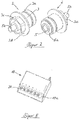
- a connection base 2 is shown in Figure 2 shown.
- the in Figure 2 left illustration shows a perspective view of the connection base 2 from within the housing, that is to say the inner end face of the connection base 2
- the FIG Figure 2 right illustration shows a perspective view of the connection base 2 from outside the housing, that is to say the outer end face of the connection base 2.
- connection base 2 of the embodiment shown in the figures mentioned has a receiving socket 3, which extends through a bore 4a in a Figure 4 illustrated housing wall 4b of a housing 4 extends therethrough and is fastened there.
- the area to the left of the housing wall 4b represents the inside of the housing 4, while the area to the right of the housing wall 4b is located outside the housing 4.
- the receiving bushing 3 can be surrounded by a cylindrical gap S or alternatively by a threaded gap in the area of the passage through the pressure-resistant housing.
- connection base 2 is fastened to the housing wall 4b with the aid of an externally threaded section 3a of the receiving socket 3 adjoining the outer end face, a fastening element (not shown) (e.g. a fastening nut or an internally threaded sleeve) and an integrally formed abutment flange 3b, which is located inside the housing is located.
- a fastening element e.g. a fastening nut or an internally threaded sleeve
- an integrally formed abutment flange 3b which is located inside the housing is located.
- the cylindrical gap S between the receiving socket 3 of the connection base 2 and the Bore 4a of the housing wall 4b is used in a known manner as ignition breakdown protection.
- an external hexagon area 3c formed on the receiving socket 3 adjacent to the abutment flange 3b.
- a single contact bolt 5 is mounted in an insulating sleeve 6 in an area arranged adjacent to the outer end face of the connection base 2.
- the contact bolt 5 axially penetrates the receiving socket 3 towards the inside of the housing 4 and is embedded in the area adjacent to the inner face of the connection base 2 in potting compound 7, which is located radially between the contact bolt 5 and a recess in the receiving socket 3.
- the potting compound 7, like the gaps (not shown in more detail) between the insulating sleeve 6 and the receiving socket 3 and between the insulating sleeve 6 and the contact bolt 5, serves to protect against ignition breakdown.
- the contact pin 5 is provided at its (inner) end located in the area of the inner face of the connection base 2 with a threaded pin 5a, with the aid of which an electrical connection to a component located inside the housing 4 can be established.
- a central axial bore 5b is made in the contact bolt 5, which is provided with an internal thread and, in the present exemplary embodiment, is designed as a blind bore.
- the axial bore 5b can be one in the Figure 4
- Contact screw 8 shown only hinted at can be screwed in to fix a cable K to be connected to the connection base 2 in a current-transmitting manner with the aid of a cable lug 9 of the cable K, also shown only hinted at.
- a cable gland V is created.
- the relatively large contact areas between the contact screw 8, cable lug 9 and contact bolt 5 and the high surface pressures that can be generated by the cable gland V can generate large currents and therefore large electrical powers are transmitted from the detachable cable connection of the industrial truck according to the invention.
- the described cable connection in the connection area of the cable K is sealed to the outside, i.e. to the environment.
- a sheath is provided which surrounds the electrical contact area and consists of several individual sheaths.
- the cable lug 9 is also provided with a sheathing 9a, which closes the electrical contact area between a screw head 8a of the contact screw 8 and the cable lug 9 and between the cable lug 9 and the contact bolt 5 to the environment.
- the screw head 8a of the contact screw 8 has a casing 8b.
- the sheaths 9a, 8b can consist of rubber, plastic or some other material suitable for electrical insulation.
- a radial flange 6a is also formed on an end of the insulating sleeve 6 adjacent to the connection area.
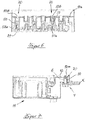
- FIG. 5 shows an electronic control unit 10 (for example a power control unit) with a plurality of single-pole cable connections, each of which has a connection socket 20 in a housing wall 10a.
- Connection base 20 shown in more detail differ from that in FIGS Figures 2 , 3 and 4 connection base 2 shown by an integrated design.
- the receiving sockets 3 are omitted and a contact bolt 50 is received directly in the housing wall 10a with the interposition of the insulating sleeve 6.
- five of the six illustrated contact bolts 50 are each provided with a central axial bore 50c with an internal thread at the end located in the area of the inner face of the connection base 20 - analogous to the end located outside the housing wall 10a.
- a second contact screw 81 can be screwed into the axial bore 50c, with which a electrical connection can be established.
- a central axial bore 50b with an internal thread is made in the contact bolt 50 at its (outer) end located in the area of the outer end face of the connection base 20, in order to be able to connect a cable there.
- Both axial bores 50b, 50c are each designed as blind bores.
- On one of the illustrated contact pins 50 is analogous to the contact pin 5 of the Figure 4 a threaded pin 50a is formed on the inner end face.
- FIG. 7 shows a section through a power control unit 11 of an electric motor of the inventive, explosion-proof industrial truck.
- the connection base 20 shown there has a contact pin 50 analogous to that in the embodiment of FIG Figures 2 , 3 and 4
- the contact pin 5 used as well as an insulating sleeve 6 surrounding it, but no receiving socket, because here too - as in the exemplary embodiment according to FIG Figure 6 - an integrated construction is used.
- the threaded pin 50a formed on the inner end of the contact bolt 50 is screwed to a rigid current-carrying holder 12 (eg rail) so that an assembly function is also achieved in addition to the current transmission function.
Landscapes
- Engineering & Computer Science (AREA)
- Structural Engineering (AREA)
- Life Sciences & Earth Sciences (AREA)
- Geology (AREA)
- Mechanical Engineering (AREA)
- Transportation (AREA)
- Chemical & Material Sciences (AREA)
- Combustion & Propulsion (AREA)
- Civil Engineering (AREA)
- Connector Housings Or Holding Contact Members (AREA)
- Cable Accessories (AREA)
Claims (9)
- Convoyeur au sol antidéflagrant comprenant une liaison par câble détachable qui comporte une embase de liaison (2 ; 20) qui peut être fixée dans une paroi de boîtier (4b) d'un boîtier (4) résistant à la pression et qui est traversé de manière antidéflagrante et à laquelle un câble (K) peut être raccordé dans une zone de raccordement, disposée à l'extérieur du boîtier (4), de la liaison par câble, caractérisé en ce que la base de liaison (2; 20) comporte une seule broche de contact (5) à laquelle le câble (K) peut être raccordé au moyen d'un passe-câble à vis (V) étanche à l'environnement, la liaison par câble étant étanchéifié par rapport à de l'environnement au niveau de la broche de contact (5) dans la zone de raccordement du câble (K), la broche de contact (5) étant entourée d'un manchon isolant (6) au niveau duquel une bride radiale (6a) est formée à une extrémité disposée dans la zone du côté frontal extérieur de l'embase de liaison (2 ; 20), un alésage axial central (5b) pourvu d'un filetage intérieur étant ménagé dans la broche de contact (5), alésage dans lequel une vis de contact (8), avec laquelle une cosse de câble (9) disposée sur le câble (4) du côté extrémité et munie d'une gaine (9a) conçue comme une gaine individuelle peut être fixée à la broche de contact (5), peut être vissée depuis un côté frontal, extérieur par rapport au boîtier (4), de l'embase de liaison (2 ; 20) pour raccorder le câble (K) de la broche de contact (5), et une tête de vis (8a) de la vis de contact (8) étant pourvue d'une gaine (8b) conçue comme une gaine individuelle.
- Convoyeur au sol antidéflagrant selon la revendication 1, caractérisé en ce que l'embase de liaison (2) comporte une douille de réception (3) qui supporte la broche de contact (5).
- Convoyeur au sol antidéflagrant selon la revendication 2, caractérisé en ce que la douille de réception (3) est munie de moyens de fixation dans la paroi de boîtier (4a).
- Convoyeur au sol antidéflagrant selon la revendication 3, caractérisé en ce que la douille de réception (3) est munie, à une extrémité disposée dans la zone du côté frontal extérieur de l'embase de liaison (2), d'une portion de filetage extérieur (3a) et, axialement à distance de celle-ci, d'une bride de butée (3b).
- Convoyeur au sol antidéflagrant selon la revendication 4, caractérisé en ce que la douille de réception (3) comporte des moyens destinés à appliquer un couple de retenue lors du vissage et du desserrage d'un élément de fixation qui est fonctionnellement relié à la portion filetée extérieure (3a).
- Convoyeur au sol antidéflagrant selon l'une des revendications 2 à 5, caractérisé en ce qu'une matière d'enrobage (7) est introduite entre la douille de réception (3) et la broche de contact (5).
- Convoyeur au sol antidéflagrant selon l'une des revendications 1 à 6, caractérisé en ce que la broche de contact (5) est pourvue d'une goupille filetée (5a ; 50a) à une extrémité qui est disposée dans la zone d'un côté frontal, intérieur par rapport au boîtier (4a), de l'embase de liaison (2 ; 20).
- Convoyeur au sol antidéflagrant selon l'une des revendications 1 à 7, caractérisé en ce que, à une extrémité disposée dans la zone du côté frontal intérieur de l'embase de liaison (2 ; 20), la broche de contact (50) comporte un alésage axial central (50c) qui est muni d'un alésage intérieur et dans lequel peut être vissée une deuxième vis de contact (81).
- Convoyeur au sol antidéflagrant selon l'une des revendications 1 à 8, caractérisé en ce que la liaison par câble est disposée au niveau d'une unité de commande de puissance (11).
Applications Claiming Priority (1)
| Application Number | Priority Date | Filing Date | Title |
|---|---|---|---|
| DE102016117586.2A DE102016117586A1 (de) | 2016-09-19 | 2016-09-19 | Explosionsgeschütztes Flurförderzeug |
Publications (2)
| Publication Number | Publication Date |
|---|---|
| EP3297096A1 EP3297096A1 (fr) | 2018-03-21 |
| EP3297096B1 true EP3297096B1 (fr) | 2021-11-03 |
Family
ID=59761826
Family Applications (1)
| Application Number | Title | Priority Date | Filing Date |
|---|---|---|---|
| EP17188994.2A Active EP3297096B1 (fr) | 2016-09-19 | 2017-09-01 | Chariot de manutention protégé contre les explosions |
Country Status (2)
| Country | Link |
|---|---|
| EP (1) | EP3297096B1 (fr) |
| DE (1) | DE102016117586A1 (fr) |
Families Citing this family (2)
| Publication number | Priority date | Publication date | Assignee | Title |
|---|---|---|---|---|
| CN111864673A (zh) * | 2020-09-02 | 2020-10-30 | 江苏捷顺机电工程有限公司 | 一种快装嵌入式86接线盒 |
| CN114314438B (zh) * | 2022-01-07 | 2023-07-04 | 安徽宇锋智慧物联科技有限公司 | 一种用于防爆立库的防爆堆垛式agv |
Family Cites Families (7)
| Publication number | Priority date | Publication date | Assignee | Title |
|---|---|---|---|---|
| EP1737072A3 (fr) * | 2005-06-21 | 2008-12-03 | Abertax Research And Development Ltd. | Système de connexion pour connecteurs de batterie |
| DE102005047979A1 (de) * | 2005-10-06 | 2007-04-12 | Juli Motorenwerk, K.S. | Rotierende elektrische Maschine und Verfahren zur Herstellung einr rotierenden elektrischen Maschine |
| JP4650691B2 (ja) * | 2006-03-03 | 2011-03-16 | 住友電装株式会社 | 電気接続構造 |
| JP2009043685A (ja) * | 2007-08-10 | 2009-02-26 | Toyota Industries Corp | 外部端子接続部用キャップ |
| JP5397355B2 (ja) * | 2009-10-19 | 2014-01-22 | 株式会社デンソー | 車両用電源装置 |
| DE102013212233A1 (de) * | 2013-06-26 | 2014-12-31 | Zf Friedrichshafen Ag | Vorrichtung zur mechanischen und elektrischen Verbindung von Leitungsadern eines Kabels mit Leitungsanschlüssen einer elektrischen Baugruppe |
| DE102013113013A1 (de) | 2013-07-05 | 2015-01-08 | Linde Material Handling Gmbh | Kabeldurchführung, insbesondere für eine explosionsgeschützte mobile Arbeitsmaschine, sowie explosionsgeschützte mobile Arbeitsmaschine |
-
2016
- 2016-09-19 DE DE102016117586.2A patent/DE102016117586A1/de not_active Withdrawn
-
2017
- 2017-09-01 EP EP17188994.2A patent/EP3297096B1/fr active Active
Non-Patent Citations (1)
| Title |
|---|
| None * |
Also Published As
| Publication number | Publication date |
|---|---|
| DE102016117586A1 (de) | 2018-03-22 |
| EP3297096A1 (fr) | 2018-03-21 |
Similar Documents
| Publication | Publication Date | Title |
|---|---|---|
| EP2845277B1 (fr) | Boîtier de traversée | |
| EP2567426B1 (fr) | Connexion de module électrique d'un véhicule à moteur | |
| EP3350851B1 (fr) | Module de batterie, son procédé de fabrication ainsi que batterie | |
| EP2845268B1 (fr) | Clip de fixation de câble pour l'électronique des modules | |
| DE102013212233A1 (de) | Vorrichtung zur mechanischen und elektrischen Verbindung von Leitungsadern eines Kabels mit Leitungsanschlüssen einer elektrischen Baugruppe | |
| DE112012006071T5 (de) | Sperrmechanismus für Motor, und Motor | |
| EP2151908B1 (fr) | Machine dynamoélectrique dotée d'un boîtier de connexion en plusieurs parties | |
| EP3166214A1 (fr) | Unité d'électronique pour un moteur électrique | |
| EP3297096B1 (fr) | Chariot de manutention protégé contre les explosions | |
| EP3427557B1 (fr) | Appareil de commande | |
| DE102014201190A1 (de) | Verbindungsanordnung für Leistungsanschluss einer elektrischen Maschine | |
| EP2750268B1 (fr) | Groupe motopompe | |
| EP2728985B1 (fr) | Entraînement de réglage avec raccord enfichable électrique | |
| EP0569820B1 (fr) | Faisceau de câbles avec connecteurs pour véhicule | |
| EP3284160A1 (fr) | Actionneur pour un embrayage de véhicule automobile, comprenant un support dans lequel est maintenue une fiche et module hybride muni d'un tel actionneur | |
| WO2016066522A1 (fr) | Dispositif anti-déflagration | |
| DE102020111359A1 (de) | Berührgeschützte Verbindungsanordnung von zwei elektrischen Leitern sowie Kraftfahrzeug mit einer solchen Verbindungsanordnung | |
| DE102013217836B4 (de) | Traktionsbatterie für ein Fahrzeug sowie Verfahren zur Herstellung dafür | |
| DE102006015310B3 (de) | Sammelschienenkupplung | |
| EP1320290A2 (fr) | Boítier de distribution | |
| DE102015207628A1 (de) | Gehäuse für eine Zwillingsanordnung von Elektromaschinen und Zwei-Motorenantrieb | |
| DE102013113013A1 (de) | Kabeldurchführung, insbesondere für eine explosionsgeschützte mobile Arbeitsmaschine, sowie explosionsgeschützte mobile Arbeitsmaschine | |
| WO2024235753A1 (fr) | Connecteur de module pour connexion électrique à une connexion de pôle de module d'un module de batterie, connexion de pôle de module et ensemble de connexion | |
| DE4002244C1 (fr) | ||
| EP2820696A1 (fr) | Batterie comprenant au moins deux éléments et comprenant au moins un élément de liaison |
Legal Events
| Date | Code | Title | Description |
|---|---|---|---|
| PUAI | Public reference made under article 153(3) epc to a published international application that has entered the european phase |
Free format text: ORIGINAL CODE: 0009012 |
|
| STAA | Information on the status of an ep patent application or granted ep patent |
Free format text: STATUS: THE APPLICATION HAS BEEN PUBLISHED |
|
| AK | Designated contracting states |
Kind code of ref document: A1 Designated state(s): AL AT BE BG CH CY CZ DE DK EE ES FI FR GB GR HR HU IE IS IT LI LT LU LV MC MK MT NL NO PL PT RO RS SE SI SK SM TR |
|
| AX | Request for extension of the european patent |
Extension state: BA ME |
|
| STAA | Information on the status of an ep patent application or granted ep patent |
Free format text: STATUS: REQUEST FOR EXAMINATION WAS MADE |
|
| 17P | Request for examination filed |
Effective date: 20180918 |
|
| RBV | Designated contracting states (corrected) |
Designated state(s): AL AT BE BG CH CY CZ DE DK EE ES FI FR GB GR HR HU IE IS IT LI LT LU LV MC MK MT NL NO PL PT RO RS SE SI SK SM TR |
|
| STAA | Information on the status of an ep patent application or granted ep patent |
Free format text: STATUS: EXAMINATION IS IN PROGRESS |
|
| 17Q | First examination report despatched |
Effective date: 20200304 |
|
| GRAP | Despatch of communication of intention to grant a patent |
Free format text: ORIGINAL CODE: EPIDOSNIGR1 |
|
| STAA | Information on the status of an ep patent application or granted ep patent |
Free format text: STATUS: GRANT OF PATENT IS INTENDED |
|
| RIC1 | Information provided on ipc code assigned before grant |
Ipc: H01R 4/70 20060101AFI20210422BHEP Ipc: H01R 13/533 20060101ALI20210422BHEP Ipc: B66F 9/24 20060101ALN20210422BHEP Ipc: H01R 11/12 20060101ALN20210422BHEP Ipc: H01R 13/527 20060101ALN20210422BHEP |
|
| INTG | Intention to grant announced |
Effective date: 20210514 |
|
| GRAS | Grant fee paid |
Free format text: ORIGINAL CODE: EPIDOSNIGR3 |
|
| GRAA | (expected) grant |
Free format text: ORIGINAL CODE: 0009210 |
|
| STAA | Information on the status of an ep patent application or granted ep patent |
Free format text: STATUS: THE PATENT HAS BEEN GRANTED |
|
| AK | Designated contracting states |
Kind code of ref document: B1 Designated state(s): AL AT BE BG CH CY CZ DE DK EE ES FI FR GB GR HR HU IE IS IT LI LT LU LV MC MK MT NL NO PL PT RO RS SE SI SK SM TR |
|
| REG | Reference to a national code |
Ref country code: GB Ref legal event code: FG4D Free format text: NOT ENGLISH |
|
| REG | Reference to a national code |
Ref country code: AT Ref legal event code: REF Ref document number: 1444822 Country of ref document: AT Kind code of ref document: T Effective date: 20211115 Ref country code: CH Ref legal event code: EP |
|
| REG | Reference to a national code |
Ref country code: IE Ref legal event code: FG4D Free format text: LANGUAGE OF EP DOCUMENT: GERMAN |
|
| REG | Reference to a national code |
Ref country code: DE Ref legal event code: R096 Ref document number: 502017011889 Country of ref document: DE |
|
| REG | Reference to a national code |
Ref country code: LT Ref legal event code: MG9D |
|
| REG | Reference to a national code |
Ref country code: NL Ref legal event code: MP Effective date: 20211103 |
|
| PG25 | Lapsed in a contracting state [announced via postgrant information from national office to epo] |
Ref country code: RS Free format text: LAPSE BECAUSE OF FAILURE TO SUBMIT A TRANSLATION OF THE DESCRIPTION OR TO PAY THE FEE WITHIN THE PRESCRIBED TIME-LIMIT Effective date: 20211103 Ref country code: LT Free format text: LAPSE BECAUSE OF FAILURE TO SUBMIT A TRANSLATION OF THE DESCRIPTION OR TO PAY THE FEE WITHIN THE PRESCRIBED TIME-LIMIT Effective date: 20211103 Ref country code: FI Free format text: LAPSE BECAUSE OF FAILURE TO SUBMIT A TRANSLATION OF THE DESCRIPTION OR TO PAY THE FEE WITHIN THE PRESCRIBED TIME-LIMIT Effective date: 20211103 Ref country code: BG Free format text: LAPSE BECAUSE OF FAILURE TO SUBMIT A TRANSLATION OF THE DESCRIPTION OR TO PAY THE FEE WITHIN THE PRESCRIBED TIME-LIMIT Effective date: 20220203 |
|
| PG25 | Lapsed in a contracting state [announced via postgrant information from national office to epo] |
Ref country code: IS Free format text: LAPSE BECAUSE OF FAILURE TO SUBMIT A TRANSLATION OF THE DESCRIPTION OR TO PAY THE FEE WITHIN THE PRESCRIBED TIME-LIMIT Effective date: 20220303 Ref country code: SE Free format text: LAPSE BECAUSE OF FAILURE TO SUBMIT A TRANSLATION OF THE DESCRIPTION OR TO PAY THE FEE WITHIN THE PRESCRIBED TIME-LIMIT Effective date: 20211103 Ref country code: PT Free format text: LAPSE BECAUSE OF FAILURE TO SUBMIT A TRANSLATION OF THE DESCRIPTION OR TO PAY THE FEE WITHIN THE PRESCRIBED TIME-LIMIT Effective date: 20220303 Ref country code: PL Free format text: LAPSE BECAUSE OF FAILURE TO SUBMIT A TRANSLATION OF THE DESCRIPTION OR TO PAY THE FEE WITHIN THE PRESCRIBED TIME-LIMIT Effective date: 20211103 Ref country code: NO Free format text: LAPSE BECAUSE OF FAILURE TO SUBMIT A TRANSLATION OF THE DESCRIPTION OR TO PAY THE FEE WITHIN THE PRESCRIBED TIME-LIMIT Effective date: 20220203 Ref country code: NL Free format text: LAPSE BECAUSE OF FAILURE TO SUBMIT A TRANSLATION OF THE DESCRIPTION OR TO PAY THE FEE WITHIN THE PRESCRIBED TIME-LIMIT Effective date: 20211103 Ref country code: LV Free format text: LAPSE BECAUSE OF FAILURE TO SUBMIT A TRANSLATION OF THE DESCRIPTION OR TO PAY THE FEE WITHIN THE PRESCRIBED TIME-LIMIT Effective date: 20211103 Ref country code: HR Free format text: LAPSE BECAUSE OF FAILURE TO SUBMIT A TRANSLATION OF THE DESCRIPTION OR TO PAY THE FEE WITHIN THE PRESCRIBED TIME-LIMIT Effective date: 20211103 Ref country code: GR Free format text: LAPSE BECAUSE OF FAILURE TO SUBMIT A TRANSLATION OF THE DESCRIPTION OR TO PAY THE FEE WITHIN THE PRESCRIBED TIME-LIMIT Effective date: 20220204 Ref country code: ES Free format text: LAPSE BECAUSE OF FAILURE TO SUBMIT A TRANSLATION OF THE DESCRIPTION OR TO PAY THE FEE WITHIN THE PRESCRIBED TIME-LIMIT Effective date: 20211103 |
|
| PG25 | Lapsed in a contracting state [announced via postgrant information from national office to epo] |
Ref country code: SM Free format text: LAPSE BECAUSE OF FAILURE TO SUBMIT A TRANSLATION OF THE DESCRIPTION OR TO PAY THE FEE WITHIN THE PRESCRIBED TIME-LIMIT Effective date: 20211103 Ref country code: SK Free format text: LAPSE BECAUSE OF FAILURE TO SUBMIT A TRANSLATION OF THE DESCRIPTION OR TO PAY THE FEE WITHIN THE PRESCRIBED TIME-LIMIT Effective date: 20211103 Ref country code: RO Free format text: LAPSE BECAUSE OF FAILURE TO SUBMIT A TRANSLATION OF THE DESCRIPTION OR TO PAY THE FEE WITHIN THE PRESCRIBED TIME-LIMIT Effective date: 20211103 Ref country code: EE Free format text: LAPSE BECAUSE OF FAILURE TO SUBMIT A TRANSLATION OF THE DESCRIPTION OR TO PAY THE FEE WITHIN THE PRESCRIBED TIME-LIMIT Effective date: 20211103 Ref country code: DK Free format text: LAPSE BECAUSE OF FAILURE TO SUBMIT A TRANSLATION OF THE DESCRIPTION OR TO PAY THE FEE WITHIN THE PRESCRIBED TIME-LIMIT Effective date: 20211103 Ref country code: CZ Free format text: LAPSE BECAUSE OF FAILURE TO SUBMIT A TRANSLATION OF THE DESCRIPTION OR TO PAY THE FEE WITHIN THE PRESCRIBED TIME-LIMIT Effective date: 20211103 |
|
| REG | Reference to a national code |
Ref country code: DE Ref legal event code: R097 Ref document number: 502017011889 Country of ref document: DE |
|
| PLBE | No opposition filed within time limit |
Free format text: ORIGINAL CODE: 0009261 |
|
| STAA | Information on the status of an ep patent application or granted ep patent |
Free format text: STATUS: NO OPPOSITION FILED WITHIN TIME LIMIT |
|
| 26N | No opposition filed |
Effective date: 20220804 |
|
| PG25 | Lapsed in a contracting state [announced via postgrant information from national office to epo] |
Ref country code: AL Free format text: LAPSE BECAUSE OF FAILURE TO SUBMIT A TRANSLATION OF THE DESCRIPTION OR TO PAY THE FEE WITHIN THE PRESCRIBED TIME-LIMIT Effective date: 20211103 |
|
| PG25 | Lapsed in a contracting state [announced via postgrant information from national office to epo] |
Ref country code: SI Free format text: LAPSE BECAUSE OF FAILURE TO SUBMIT A TRANSLATION OF THE DESCRIPTION OR TO PAY THE FEE WITHIN THE PRESCRIBED TIME-LIMIT Effective date: 20211103 |
|
| PG25 | Lapsed in a contracting state [announced via postgrant information from national office to epo] |
Ref country code: MC Free format text: LAPSE BECAUSE OF FAILURE TO SUBMIT A TRANSLATION OF THE DESCRIPTION OR TO PAY THE FEE WITHIN THE PRESCRIBED TIME-LIMIT Effective date: 20211103 |
|
| REG | Reference to a national code |
Ref country code: CH Ref legal event code: PL |
|
| REG | Reference to a national code |
Ref country code: BE Ref legal event code: MM Effective date: 20220930 |
|
| PG25 | Lapsed in a contracting state [announced via postgrant information from national office to epo] |
Ref country code: IT Free format text: LAPSE BECAUSE OF FAILURE TO SUBMIT A TRANSLATION OF THE DESCRIPTION OR TO PAY THE FEE WITHIN THE PRESCRIBED TIME-LIMIT Effective date: 20211103 |
|
| P01 | Opt-out of the competence of the unified patent court (upc) registered |
Effective date: 20230507 |
|
| PG25 | Lapsed in a contracting state [announced via postgrant information from national office to epo] |
Ref country code: LU Free format text: LAPSE BECAUSE OF NON-PAYMENT OF DUE FEES Effective date: 20220901 |
|
| PG25 | Lapsed in a contracting state [announced via postgrant information from national office to epo] |
Ref country code: LI Free format text: LAPSE BECAUSE OF NON-PAYMENT OF DUE FEES Effective date: 20220930 Ref country code: IE Free format text: LAPSE BECAUSE OF NON-PAYMENT OF DUE FEES Effective date: 20220901 Ref country code: CH Free format text: LAPSE BECAUSE OF NON-PAYMENT OF DUE FEES Effective date: 20220930 |
|
| PG25 | Lapsed in a contracting state [announced via postgrant information from national office to epo] |
Ref country code: BE Free format text: LAPSE BECAUSE OF NON-PAYMENT OF DUE FEES Effective date: 20220930 |
|
| REG | Reference to a national code |
Ref country code: AT Ref legal event code: MM01 Ref document number: 1444822 Country of ref document: AT Kind code of ref document: T Effective date: 20220901 |
|
| PG25 | Lapsed in a contracting state [announced via postgrant information from national office to epo] |
Ref country code: AT Free format text: LAPSE BECAUSE OF NON-PAYMENT OF DUE FEES Effective date: 20220901 |
|
| PG25 | Lapsed in a contracting state [announced via postgrant information from national office to epo] |
Ref country code: HU Free format text: LAPSE BECAUSE OF FAILURE TO SUBMIT A TRANSLATION OF THE DESCRIPTION OR TO PAY THE FEE WITHIN THE PRESCRIBED TIME-LIMIT; INVALID AB INITIO Effective date: 20170901 |
|
| PG25 | Lapsed in a contracting state [announced via postgrant information from national office to epo] |
Ref country code: CY Free format text: LAPSE BECAUSE OF FAILURE TO SUBMIT A TRANSLATION OF THE DESCRIPTION OR TO PAY THE FEE WITHIN THE PRESCRIBED TIME-LIMIT Effective date: 20211103 |
|
| PG25 | Lapsed in a contracting state [announced via postgrant information from national office to epo] |
Ref country code: MK Free format text: LAPSE BECAUSE OF FAILURE TO SUBMIT A TRANSLATION OF THE DESCRIPTION OR TO PAY THE FEE WITHIN THE PRESCRIBED TIME-LIMIT Effective date: 20211103 |
|
| PG25 | Lapsed in a contracting state [announced via postgrant information from national office to epo] |
Ref country code: MT Free format text: LAPSE BECAUSE OF FAILURE TO SUBMIT A TRANSLATION OF THE DESCRIPTION OR TO PAY THE FEE WITHIN THE PRESCRIBED TIME-LIMIT Effective date: 20211103 |
|
| PGFP | Annual fee paid to national office [announced via postgrant information from national office to epo] |
Ref country code: DE Payment date: 20250919 Year of fee payment: 9 |
|
| PGFP | Annual fee paid to national office [announced via postgrant information from national office to epo] |
Ref country code: GB Payment date: 20250923 Year of fee payment: 9 |
|
| PGFP | Annual fee paid to national office [announced via postgrant information from national office to epo] |
Ref country code: FR Payment date: 20250922 Year of fee payment: 9 |
|
| PG25 | Lapsed in a contracting state [announced via postgrant information from national office to epo] |
Ref country code: TR Free format text: LAPSE BECAUSE OF FAILURE TO SUBMIT A TRANSLATION OF THE DESCRIPTION OR TO PAY THE FEE WITHIN THE PRESCRIBED TIME-LIMIT Effective date: 20211103 |