EP3297182B1 - Procédé de détection d'état de fibre optique - Google Patents
Procédé de détection d'état de fibre optique Download PDFInfo
- Publication number
- EP3297182B1 EP3297182B1 EP16898231.2A EP16898231A EP3297182B1 EP 3297182 B1 EP3297182 B1 EP 3297182B1 EP 16898231 A EP16898231 A EP 16898231A EP 3297182 B1 EP3297182 B1 EP 3297182B1
- Authority
- EP
- European Patent Office
- Prior art keywords
- station
- otdr
- sending
- osc
- pulse
- Prior art date
- Legal status (The legal status is an assumption and is not a legal conclusion. Google has not performed a legal analysis and makes no representation as to the accuracy of the status listed.)
- Active
Links
Images







Classifications
-
- H—ELECTRICITY
- H04—ELECTRIC COMMUNICATION TECHNIQUE
- H04B—TRANSMISSION
- H04B10/00—Transmission systems employing electromagnetic waves other than radio-waves, e.g. infrared, visible or ultraviolet light, or employing corpuscular radiation, e.g. quantum communication
- H04B10/07—Arrangements for monitoring or testing transmission systems; Arrangements for fault measurement of transmission systems
- H04B10/071—Arrangements for monitoring or testing transmission systems; Arrangements for fault measurement of transmission systems using a reflected signal, e.g. using optical time domain reflectometers [OTDR]
-
- H—ELECTRICITY
- H04—ELECTRIC COMMUNICATION TECHNIQUE
- H04B—TRANSMISSION
- H04B10/00—Transmission systems employing electromagnetic waves other than radio-waves, e.g. infrared, visible or ultraviolet light, or employing corpuscular radiation, e.g. quantum communication
- H04B10/07—Arrangements for monitoring or testing transmission systems; Arrangements for fault measurement of transmission systems
- H04B10/075—Arrangements for monitoring or testing transmission systems; Arrangements for fault measurement of transmission systems using an in-service signal
- H04B10/077—Arrangements for monitoring or testing transmission systems; Arrangements for fault measurement of transmission systems using an in-service signal using a supervisory or additional signal
- H04B10/0771—Fault location on the transmission path
-
- H—ELECTRICITY
- H04—ELECTRIC COMMUNICATION TECHNIQUE
- H04B—TRANSMISSION
- H04B10/00—Transmission systems employing electromagnetic waves other than radio-waves, e.g. infrared, visible or ultraviolet light, or employing corpuscular radiation, e.g. quantum communication
- H04B10/25—Arrangements specific to fibre transmission
-
- H—ELECTRICITY
- H04—ELECTRIC COMMUNICATION TECHNIQUE
- H04J—MULTIPLEX COMMUNICATION
- H04J14/00—Optical multiplex systems
- H04J14/02—Wavelength-division multiplex systems
- H04J14/0227—Operation, administration, maintenance or provisioning [OAMP] of WDM networks, e.g. media access, routing or wavelength allocation
- H04J14/0254—Optical medium access
- H04J14/0272—Transmission of OAMP information
- H04J14/0275—Transmission of OAMP information using an optical service channel
-
- H—ELECTRICITY
- H04—ELECTRIC COMMUNICATION TECHNIQUE
- H04J—MULTIPLEX COMMUNICATION
- H04J14/00—Optical multiplex systems
- H04J14/08—Time-division multiplex systems
Definitions
- the present invention relates to the field of optical communications technologies, and in particular, to an optical fiber status detection method.
- WO 02/47293 A1 describes integrated OTDR/OSC mechanism for monitoring an optical transport system without disrupting the normal service.
- the therein described system combines two essential network components in an integrated mechanism. These components are the mandatory OSC function as part of any DWDM network, and the in-skin, in-service attributes of the OTDR engine.
- US 2004/208501 A1 describes network diagnostic systems for an optical transport network having a plurality of network elements.
- the network diagnostic system includes at least one network element having a network diagnostic operation integrated therein and operable to perform the network diagnostic operation.
- an (OTDR) is widely used for optical fiber line fault location.
- the OTDR is a precise photoelectric integration instrument made by means of back scattering generated by Rayleigh scattering and Fresnel reflection of a ray propagating in an optical fiber, is widely applied to maintenance and construction of optical cable lines, and is mainly used to measure a length of an optical fiber, propagation attenuation of the optical fiber, connector attenuation, fault location, and the like.
- a conventional OTDR is a handheld device. Using the OTDR as a test instrument is a scattered and passive manual maintenance means, higher optical fiber security requirements can be hardly ensured, and the OTDR is expensive.
- a fault in an optical fiber line is determined, a worker needs to enter a station and switches off the optical fiber line to perform a test. A long location period and a long time of service interruption cause a relatively great economic loss.
- an OTDR unit uses a wavelength independent from a service unit and an optical supervisory unit, is connected to a multiplexing/demultiplexing unit, and may implement real-time online optical fiber status detection unidirectionally.
- OADM optical add/drop multiplexer
- an OTDR unit needs to be configured for an egress in each direction. Therefore, not only many units are configured, but also a large amount of cabinet space or device slots need to be occupied. Consequently, device costs and installation costs are both very high.
- an OTDR unit is integrated in a station and a multipath optical switch for the OTDR unit is added to monitor optical fiber alarms in multiple directions in real time, thereby reducing costs for configuring OTDR units in multiple directions.
- real-time online optical fiber status detection cannot be implemented and line assembly is relatively complex.
- the foregoing two solutions are both solutions in which an OTDR is used as an independent unit and integrated in a station, and does not share a wavelength with a service unit or an optical supervisory unit. Further, the foregoing two solutions need to modify an existing system card, for example, adding an access port of an OTDR unit to a multiplexing/demultiplexing unit.
- the integrated OTDR is an independent unit. Installation of the OTDR unit occupies space of a cabinet or a device slot, and has high costs.
- aspects of the present invention provide an optical fiber status detection method as defined by the independent claim so as to resolve prior-art problems of relatively high costs and complex assembly caused by separately integrating an OTDR unit.
- an optical fiber status detection method including: alternately sending, by a first station, an OTDR pulse and OSC data to a second station on a same channel, where the second station is a neighboring station of the first station; and receiving, by the first station, reflection light returned by the OTDR pulse by using an optical fiber between the first station and the second station, and obtaining an OTDR probe value according to the reflection light.
- the same channel indicates using a same wavelength, a same wavelength sct, or a same protocol data frame.
- the first station receives an OTDR probe instruction delivered by a network management system, where the OTDR probe instruction includes a quantity N of OTDR probe values that need to be obtained during this time of OTDR probe, and N is a positive integer.
- the first station determines, according to the quantity N of the OTDR probe values and a preset quantity n of OTDR pulses sent for a single time, that OTDR pulse sending needs to be performed for M times. That is, the OTDR pulses are sent in fragments, thereby ensuring no packet loss and no bit error in OSC data communication between stations.
- the first station may alternately send the OTDR pulse and the OSC data to the second station on the same channel in, but not limited to, the following two manners.
- a first manner in a wavelength division multiplexing system using TDM transmission, the first station may insert one time of OTDR pulse sending between any two adjacent OSC data frames until the M times of OTDR pulse sending are completed.
- the quantity n of OTDR pulses sent for a single time is mainly determined by a buffer size of a buffer module of the optical supervisory unit in the first station, a service bandwidth, and a time for sending a single OTDR pulse.
- a buffer module in a first optical supervisory unit of the first station buffers OSC data that should be sent during sending of the n OTDR pulses as first buffer data, and sends the first buffer data to the second station by using an OSC module in the first optical supervisory unit after sending of the n OTDR pulses is completed. Further, the buffer module in the first optical supervisory unit buffers the OSC data that should be sent during sending of the first buffer data as second buffer data, and sends the second buffer data by using the OSC module in the first optical supervisory unit after sending of the first buffer data is completed, and the rest can be deduced by analogy.
- the optical supervisory unit does not occupy all egress bandwidths, reserves some redundancy bandwidths, and only occupies the redundancy bandwidth when the buffer module of the first optical supervisory unit has buffer data. Therefore, the OSC module in the first optical supervisory unit occupies all the egress bandwidths for sending the buffer data. After a period of time, the buffer module does not have buffer data, and recovers to a normal OSC data sending state.
- the first station may insert at least one time of OTDR pulse sending between any two adjacent OSC data packets until the M times of OTDR pulse sending are completed.
- the first station may send OTDR pulses (that is, N pulses) for M times between any two adjacent OSC data packets, that is, sending, between any two adjacent OSC data packets in a centralized manner, the N pulses that need to be sent.
- OTDR pulses that is, N pulses
- a second possible implementation manner when determining that a current link is idle, the first station inserts at least one time of OTDR pulse sending during an interval of sending a maintenance packet, until the M times of OTDR pulse sending are completed.
- a third possible implementation manner when determining that an OSC data packet is being sent on a current link, the first station inserts at least one time of OTDR pulse sending during an interval of sending the OSC data packet, until the M times of OTDR pulse sending are completed.
- the first station may send an OTDR probe start instruction to the second station, and the OTDR probe start instruction is used to instruct the second station to switch from a receiving state of receiving the OSC data to a silent state of waiting for OTDR probe. Therefore, synchronization of the first station and the second station can be ensured, and it is ensured that the second station can latch incomplete OSC data in real time.
- the first station may send a preset physical layer recovery message to the second station, and the preset physical layer recovery message is used to instruct the second station to switch from the silent state of waiting for OTDR probe to the receiving state of receiving the OSC data.
- the first station sends the OSC data to the second station.
- the first station after the first station sends the preset physical layer recovery message to the second station, when determining that a preset physical layer recovery acknowledgment message fed back by the second station is not received during preset duration, the first station sends the OSC data to the second station. Therefore, system reliability can be ensured, thereby avoiding that an optical fiber has a fault, and cannot recover to a receiving state in time to perform fault alarming during sending of the OTDR pulse.
- an optical supervisory unit including at least: an OTDR module, an OSC module, and a switching control module, where
- the optical supervisory unit further includes a buffer module.
- the buffer module is configured to buffer OSC data generated when the OTDR module sends the OTDR pulse.
- the optical supervisory unit further includes an optical-to-electrical conversion module.
- the optical-to-electrical conversion module is configured to convert the OTDR pulse to a corresponding optical signal, convert an electrical signal corresponding to the first OSC data to a corresponding optical signal, and convert a received optical signal corresponding to the second OSC data to a corresponding electrical signal.
- a station including a service unit, an optical supervisory unit, a main control unit, and a multiplexing/demultiplexing unit.
- the optical supervisory unit can implement optical fiber status detection in the foregoing embodiment.
- an OTDR pulse and OSC data are alternately sent to a second station on a same channel, thereby resolving problems of relatively high costs and complex assembly caused by separately integrating an OTDR unit in a WDM system, and meeting ordinary maintenance requirements for optical fiber lines.
- Faults of an optical fiber in a line of the WDM system for example, optical fiber problems such as aging of the optical fiber, external damage of the optical fiber, optical fiber curling, large-angle bending, and bearing of a relatively large tensile force lead to service and communication degradation, a high bit error rate, and even service interruption.
- a performance state of an optical fiber in a network may be discovered in time by monitoring the real-time performance state of the optical fiber by using the method provided in the embodiments of the present invention, and prevention in advance and in-time repair can be performed, thereby greatly improving network reliability.
- Embodiments of the present invention provide an optical fiber status detection method, so as to resolve prior-art problems of relatively high costs and complex assembly caused by separately integrating an OTDR unit. Examples of a corresponding optical supervisory unit and a corresponding station, which are not part of the claimed invention are also provided.
- the method, the optical supervisory unit, and the station are based on a same inventive concept. Because principles for resolving problems by the method, the optical supervisory unit, and the station are similar, implementation of the apparatus and implementation of the method may refer to each other, and details of repetitions are not described herein again.
- An optical wavelength division multiplexing transmission system is a main platform used for current trunk transmission and metropolitan area core network multiservice transmission, and a basic principle of the system is that a transmit end of an optical system multiplexes, by using a wavelength division multiplexer (multiplexer), optical carriers of input signals separately modulated in different wavelengths, and then transmits the multiplexed carriers to a remote end by using an optical fiber.
- a receive end of the optical system separates these optical carriers of different signals by using another wavelength division multiplexer (demultiplexer), and converts optical signals into corresponding electrical signals to complete long-haul transmission. Therefore, the Wavelength division multiplexing (WDM) system has advantages of great transmission capacity, easy expansion, and reliable transmission, and is highly ranked in a communications network.
- WDM Wavelength division multiplexing
- FIG. 2 is a schematic structural diagram of a basic point-to-point WDM system.
- Each station mainly includes a main control unit, a service unit, a multiplexing/demultiplexing unit, and an optical supervisory unit.
- the main control unit is configured to receive a command from a network management system, execute or receive parameter configuration, deliver the parameter configuration to another unit, and report alarms in the station to the network management system.
- the service unit is configured to separately convert multiple electrical signals into corresponding optical signals of particular wavelengths and separately convert multiple optical signals of particular wavelengths into corresponding electrical signals.
- the multiplexing/demultiplexing unit is configured to convert multiple independent optical signals of particular wavelengths into multiplexed signals and convert the multiplexed signals into multiple independent optical signals of particular wavelengths.
- the optical supervisory unit is configured to implement communication between stations and complete management and control of the WDM system. For example, as shown in FIG.
- the optical supervisory unit may transfer alarm information between the station A and the station B in real time and report the alarm information to the network management system by using the main control unit.
- the optical supervisory unit may also control parameter adjustment of an optical system according to an optical system parameter adjustment instruction delivered by the network management system.
- an embodiment of the present invention provides an optical supervisory unit 300, including at least: an OTDR module 31, an Optical Supervisory Channel (OSC) module 32, and a switching control module 33.
- an optical supervisory unit 300 including at least: an OTDR module 31, an Optical Supervisory Channel (OSC) module 32, and a switching control module 33.
- OSC Optical Supervisory Channel
- the OTDR module 31 is configured to send an OTDR pulse, and obtain an OTDR probe value according to received reflection light returned by the OTDR pulse by using an optical fiber between a first station and a second station; the optical supervisory unit 300 is located on the first station, and the second station is a neighboring station of the first station.
- the OTDR pulse is an optical pulse for measuring a length of an optical fiber, propagation attenuation of the optical fiber, splice attenuation, and fault location.
- the OTDR module 31 may generate an OTDR probe pulse with an adjustable pulse width.
- the OTDR module 31 may implement optical-to-electrical conversion on the reflection light, perform sampling analysis, obtain an OTDR probe value, and upload the obtained OTDR probe value to a main control unit in the first station.
- the main control unit further uploads the OTDR probe value to a network management system.
- the OSC module 32 is configured to send first OSC data to the second station and receive second OSC data sent by the second station.
- the OSC data refers to monitoring information, orderwire information, and alarm information of the network management system transmitted between stations.
- the OSC module 32 completes a conventional optical supervisory channel function.
- a time division multiplexing (Time Division Multiplexing, TDM) transmission manner may be used.
- the switching control module 33 directly controls the OSC data.
- a transmission manner of packet communication is used, and the switching control module 33 and the main control unit jointly control the OSC data.
- the switching control module 33 is configured to control the OTDR module 31 and the OSC module 32 to perform alternate sending of the OTDR pulse and the first OSC data, and forward the second OSC data sent by the second station to the OSC module 32.
- the optical supervisory unit 300 further includes a buffer module 34.
- the buffer module 34 is configured to buffer OSC data generated when the OTDR module 30 sends the OTDR pulse.
- the buffer module 34 when the optical supervisory unit 300 transmits the OSC data in a TDM transmission manner, the buffer module 34 is in the optical supervisory unit 300.
- the buffer module 34 when the optical supervisory unit 300 transmits the OSC data in a transmission manner of packet communication, the buffer module 34 may be in the main control unit of the first station.
- the optical supervisory unit 300 further includes an optical-to-electrical conversion module 35.
- the optical-to-electrical conversion module 35 is configured to convert the OTDR pulse to a corresponding optical signal, convert an electrical signal corresponding to the first OSC data to a corresponding optical signal, and convert a received optical signal corresponding to the second OSC data to a corresponding electrical signal.
- An embodiment of the present invention further provides a station, including the optical supervisory unit shown in FIG. 3 .
- the station 400 includes a service unit 401, an optical supervisory unit 402, a main control unit 403, and a multiplexing/demultiplexing unit 404, where a function of the optical supervisory unit 402 is the same as that of the optical supervisory unit shown in FIG. 3 .
- an embodiment of the present invention provides an optical fiber status detection method, including the following steps.
- Step 500 A first station alternately sends an OTDR pulse and OSC data to a second station on a same channel, where the second station is a neighboring station of the first station.
- the first station here is the station shown in FIG. 4 .
- the same channel includes a transmission channel using a same wavelength, a same wavelength set, or a same protocol data frame.
- Step 510 The first station receives reflection light returned by the OTDR pulse by using an optical fiber between the first station and the second station, and obtains an OTDR probe value according to the reflection light.
- the first station receives an OTDR probe instruction delivered by a network management system.
- the OTDR probe instruction includes a quantity N of OTDR probe values that need to be obtained during this time of OTDR probe, and N is a positive integer.
- the first station determines, according to the quantity N of the OTDR probe values and a preset quantity n of OTDR pulses sent for a single time, that OTDR pulse sending needs to be performed for M times. That is, the OTDR pulses are sent in fragments.
- the first station may alternately send the OTDR pulse and the OSC data to the second station on the same channel in, but not limited to, the following two manners.
- a first manner in a wavelength division multiplexing system using TDM transmission, the first station may insert one time of OTDR pulse sending between any two adjacent OSC data frames until the M times of OTDR pulse sending are completed.
- N OTDR pulses are most preferably separately sent among multiple neighboring OSC data frames, because long time interruption of OSC data sending may cause problems that a network element is detached and the alarm information cannot be reported in time. Therefore, the N pulses need to be divided into many small fragments to be sent, so as to ensure no packet loss and no bit error in OSC data communication between the first station and the second station.
- the quantity n of OTDR pulses sent for a single time is mainly determined by a buffer size of a buffer module of the optical supervisory unit in the first station, a service bandwidth, and a time for sending a single OTDR pulse.
- the first station may determine, according to n max obtained through calculation, a quantity n of OTDR pulses sent for a single time, and n ⁇ n max .
- the OSC data that should be sent when the OTDR pulses are sent further needs to be buffered.
- a buffer module in a first optical supervisory unit of the first station buffers OSC data that should be sent during sending of the n OTDR pulses as first buffer data, and sends the first buffer data to the second station by using an OSC module in the first optical supervisory unit after sending of the n OTDR pulses is completed.
- the buffer module in the first optical supervisory unit buffers the OSC data that should be sent during sending of the first buffer data as second buffer data, and sends the second buffer data by using the OSC module in the first optical supervisory unit after sending of the first buffer data is completed, and the rest can be deduced by analogy.
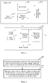
- the optical supervisory unit does not occupy all egress bandwidths, reserves some redundancy bandwidths, and only occupies the redundancy bandwidth when the buffer module of the first optical supervisory unit has buffer data. Therefore, when sending the foregoing buffer data, the OSC module in the first optical supervisory unit uses a data area (that is, a service bandwidth) and a redundancy bandwidth that are shown in FIG. 5 . After a period of time, the buffer module does not have buffer data and recovers to a normal OSC data sending state, that is, only the data area is occupied to send the OSC data.
- a sending time of the buffered OSC data generated due to sending of n OTDR pulses may also be determined.
- a time for sending OTDR pulses for a single time may be determined, that is, the time for sending OTDR pulses for a single time is equal to a sending time of each pulse multiplied by the quantity n of OTDR pulses sent for a single time. Further, the time for sending the buffered OSC data is determined according to the time for sending OTDR pulses and according to egress bandwidth information.
- the egress bandwidth information may be a ratio of the redundancy bandwidth to the service bandwidth, the redundancy bandwidth and the service bandwidth, or the like.
- a next time of OTDR pulse sending may be instantly initiated, or after several normal OSC data frames are sent, a next time of OTDR pulse sending is performed.
- the switching control module in the first optical supervisory unit may control an occasion of the next time of OTDR pulse sending, or a rule of alternately sending the OTDR pulse and the OSC data is preset in the switching control module.
- a process of alternately sending n OTDR pulses and sending OSC buffered data each time is used as an OTDR period, and the period may alternate in normal OSC data frame sending.
- Each OTDR period includes sending an OTDR probe start instruction (that is, a protocol packet shown in FIG. 6 ), sending n OTDR pulses, sending a preset physical layer recovery message (that is, a pseudorandom bit sequence (Pseudorandom Bit Sequence, PRBS) shown in FIG. 6 ), and sending OSC buffered data (that is, a frame 2, a frame 3, and a frame 4 that are shown in FIG. 6 ) to a downstream station.
- the frame 2, the frame 3, and the frame 4 may be used to send the OSC buffered data.
- sending may be performed continuously for M OTDR periods to obtain N OTDR probe values that are required to complete the current OTDR probe.
- the first station may insert at least one time of OTDR pulse sending between any two adjacent OSC data packets until the M times of OTDR pulse sending are completed.
- the first station may send OTDR pulses (that is, N pulses) for M times between any two adjacent OSC data packets, that is, sending, between any two adjacent OSC data packets in a centralized manner, the N pulses that need to be sent.
- OTDR pulses that is, N pulses
- a current link state may be an idle state, or an occupied state of sending the OSC data packet.
- N OTDR pulses may be directly sent in a centralized manner after a data packet is sent. In this case, a packet loss problem may not be caused because of data sending interruption.
- a buffer module needs to be disposed to buffer the OSC data packets that should be sent when the OTDR pulses are sent.
- the buffered OSC data packets are sent to a second station after the OTDR pulse sending is completed. In this case, capacity of the buffer module needs to be greater than a magnitude of the buffered OSC data packet generated by sending M times of the OTDR pulses, and is generally set according to an empirical value.
- a second possible implementation manner when determining that a current link is idle, the first station inserts at least one time of OTDR pulse sending during an interval of sending a maintenance packet, until the M times of OTDR pulse sending are completed.
- a same quantity of times of OTDR pulse sending may be inserted, or a different quantity of times of OTDR pulse sending may be inserted, and this is controlled by the first station.
- the first station when the link is idle, the first station sends a maintenance packet to the second station.
- the n OTDR pulses may be inserted in a sending interval of each maintenance packet until M times of OTDR pulse sending are completed.
- a third possible implementation manner when determining that an OSC data packet is being sent on a current link, the first station inserts at least one time of OTDR pulse sending during an interval of sending the OSC data packet, until the M times of OTDR pulse sending are completed.
- a same quantity of times of OTDR pulse sending may be inserted, or a different quantity of times of OTDR pulse sending may be inserted, and this is controlled by the first station.
- the OSC data packets that should be sent when the OTDR pulses are sent need to be buffered.
- n OTDR pulses are separately inserted in intervals for sending maintenance packets and information packets, until the M times of OTDR pulse sending are completed.
- the first station may send an OTDR probe start instruction to the second station, and the OTDR probe start instruction is used to instruct the second station to switch from a receiving state of receiving the OSC data to a silent state of waiting for OTDR probe.
- the first station may send a preset physical layer recovery message to the second station, for example, sending a PRBS, and the preset physical layer recovery message is used to instruct the second station to switch from the silent state of waiting for OTDR probe to the receiving state of receiving the OSC data.
- the first station sends the OSC data to the second station.
- the first station after the first station sends the preset physical layer recovery message to the second station, when determining that a preset physical layer recovery acknowledgment message fed back by the second station is not received during preset duration, the first station sends the OSC data to the second station.
- an optical supervisory unit 1100 transmits OSC data in a TDM transmission manner, and the optical supervisory unit 1100 may include an OTDR module 1101, an OSC module 1102, and a switching control module 1103.
- the OTDR module 1101 is configured to send an OTDR pulse, and obtain an OTDR probe value according to received reflection light returned by the OTDR pulse by using an optical fiber between a first station and a second station; the optical supervisory unit 1100 is located on the first station, and the second station is a neighboring station of the first station.
- the OSC module 1102 is configured to send first OSC data to the second station and receive second OSC data sent by the second station.
- the OSC module 1102 is used as a communications pipe for bearing control and monitoring information of a network management system for stations, and reported information of alarm states of the stations.
- the communications pipe is a data frame with a rate of 155.52 Mbps.
- some redundancy bandwidths are reserved in a frame structure design, so that the some redundancy bandwidths can be occupied when the OSC buffered data is sent, so as to send the OSC buffered data as soon as possible; that is, a normal data frame sends the OSC data by using a data area (that is, a service bandwidth), and the service bandwidth and the redundancy bandwidth are used to send the OSC buffered data.
- the switching control module 1103 is configured to directly control the OTDR module 1101 and the OSC module 1102 to perform alternate sending of the OTDR pulse and the first OSC data, and forward the second OSC data sent by the second station to the OSC module 1102.
- a buffer module 1104 is configured to buffer OSC data generated when the OTDR module sends the OTDR pulse.
- the optical-to-electrical conversion module 1105 is configured to convert the OTDR pulse to a corresponding optical signal, convert an electrical signal corresponding to the first OSC data to a corresponding optical signal, and convert a received optical signal corresponding to the second OSC data to a corresponding electrical signal.
- an optical fiber status detection process shown in FIG. 6 that is, a process of sending in an OTDR period specifically includes the following steps.
- Step 1301 A first main control unit in a first station receives an OTDR probe instruction delivered by a network management system, and notifies the OTDR probe instruction to a first optical supervisory unit in the first station.
- the first station here includes the optical supervisory unit shown in FIG. 11 .
- the OTDR probe instruction includes a quantity N of OTDR probe values that need to be obtained during this time of OTDR probe, and N is a positive integer.
- Step 1302 The first optical supervisory unit determines, according to a quantity N of OTDR probe values and a preset quantity n of OTDR pulses sent for a single time, a quantity M of times of OTDR pulse sending required for completing OTDR probe, where n is a preset positive integer.
- the switching control module 1103 presets the quantity n of OTDR pulses sent for a single time, and further determines, according to the quantity N of OTDR probe values, the quantity M of times of OTDR pulse sending required for completing the OTDR probe.
- Step 1303 The first optical supervisory unit sends an OTDR probe start instruction to a second optical supervisory unit of a second station.
- the OTDR probe start instruction is used to instruct the second station to switch from a receiving state of receiving OSC data to a silent state of waiting for OTDR probe, referring to the protocol packet in FIG. 6 .
- the OTDR probe start instruction may be continuously sent for multiple times.
- a station A sends the OTDR probe start instruction to a downstream station, that is, a station B, by using an overhead byte in a normal frame.
- the OTDR pulse starts to be sent after 5 frames are continuously sent, and the station A enters an OTDR probe state.
- the downstream station that is, station B needs to keep synchronized with the upstream station, that is, station A.
- the downstream station After continuously receiving 5 OTDR probe start instructions, the downstream station, that is, station B starts to latch downstream data. If the OSC data currently received by the downstream station, that is, station B is incomplete, the incomplete OSC data is latched, that is, the currently received OSC data that cannot compose a complete data packet is sent to a main control unit of the station B, so as to ensure hitless switch between the OSC data and the OTDR pulse. After completing the latching operation, the downstream station, that is, station B enters the silent state of waiting for OTDR probe.
- Step 1304 The first optical supervisory unit sends n OTDR pulses, receives reflection light returned by the n OTDR pulses by using an optical fiber between the first station and the second station, and obtains n OTDR probe values according to the reflection light.
- the optical supervisory unit includes an OTDR module 1101, and the OTDR module may generate an OTDR pulse with an adjustable pulse width.
- the OTDR pulse sent by the OTDR module is sent to the optical fiber between the first station and the second station by using an optical-to-electrical conversion module, and the OTDR module obtains an OTDR probe value according to reflection light returned by the received OTDR pulse by using the optical fiber between the first station and the second station.
- single-fiber bidirectional OTDR probe may be synchronously started so as to implement complete probe on an entire optical fiber between the two stations.
- Step 1305 The first optical supervisory unit sends a preset physical layer recovery message to the second optical supervisory unit.
- the preset physical layer recovery message is used to instruct the second station to switch from the silent state of waiting for OTDR probe to the receiving state of receiving the OSC data, referring to a PRBS in FIG. 6 .
- Step 1306 When determining that a preset physical layer recovery acknowledgment message fed back by the second optical supervisory unit is received, the first optical supervisory unit sends, to the second optical supervisory unit, buffered OSC data generated due to sending of the n OTDR pulses.
- the sent OSC buffered data is read from the buffer module in the optical supervisory unit. Referring to the frame 2, the frame 3, and the frame 4 in FIG. 6 , the frame 2, the frame 3, and the frame 4 are used to send the read OSC buffered data.
- the optical supervisory unit in the station A sends n OTDR pulses each time, before sending, to the second optical supervisory unit, the buffered OSC data generated due to sending of n OTDR pulses
- the optical supervisory unit in the station A sends the preset physical layer recovery message to the optical supervisory unit in the station B, for example, sending the PRBS.
- the preset physical layer recovery message needs to be set to an invalid frame.
- the optical supervisory unit in the station A When determining that the preset physical layer recovery acknowledgment message, such as an ACK, fed back by the second optical supervisory unit is received, the optical supervisory unit in the station A sends, to the optical supervisory unit in the station B, the buffered OSC data generated due to sending of n OTDR pulses, and recovers to an OSC data sending state.
- the preset physical layer recovery acknowledgment message such as an ACK
- timers are disposed on both the first optical supervisory unit and the second optical supervisory unit. If the preset physical layer recovery acknowledgment message fed back by the second optical supervisory unit is not received during first preset duration, the first optical supervisory unit sends, to the second optical supervisory unit, the buffered OSC data generated due to sending of n OTDR pulses. If the preset physical layer recovery message is not received during second preset duration after receiving the OTDR probe start instruction, the second optical supervisory unit recovers to an OSC receiving state.
- the first optical supervisory unit feeds back the obtained N OTDR probe values to a network management system by using a main control unit.
- a network management system may probe stations segment by segment, for example, probe an OTM station-A-B-C-D-OTM station segment by segment, or probe multiple stations in parallel, for example, probe an OTM station-A-B-C-D-OTM station in parallel.
- an optical supervisory unit 1600 transmits OSC data in a packet communication manner and includes at least: an OTDR module 1601, an OSC module 1602, a switching control module 1603, and an optical-to-electrical conversion module 1604.
- the OTDR module 1601 is configured to send an OTDR pulse, and obtain an OTDR probe value according to received reflection light returned by the OTDR pulse by using an optical fiber between a first station and a second station; the optical supervisory unit 1600 is located on the first station, and the second station is a neighboring station of the first station.
- the OSC module 1602 is configured to send first OSC data to the second station and receive second OSC data sent by the second station.
- the switching control module 1603 is configured to receive a control command of a main control unit, control the OTDR module 1601 and the OSC module 1602 to perform alternate sending of the OTDR pulse and the first OSC data, and forward the second OSC data sent by the second station to the OSC module 1602.
- the optical-to-electrical conversion module 1604 is configured to convert the OTDR pulse to a corresponding optical signal, convert an electrical signal corresponding to the first OSC data to a corresponding optical signal, and convert a received optical signal corresponding to the second OSC data to a corresponding electrical signal.
- the main control unit controls modules of the optical supervisory unit in a centralized manner, and a buffer module may be configured in the main control unit to buffer OSC data packets that need to be sent when the OTDR pulse is sent.
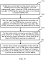
- Step 1701 A first main control unit in a first station receives an OTDR probe instruction delivered by a network management system, where the OTDR probe instruction includes N OTDR probe values that need to be obtained in current OTDR probe, and N is a positive integer.
- Step 1702 The first main control unit determines, according to a quantity N of the OTDR probe values and a preset quantity n of OTDR pulses sent for a single time, that OTDR pulse sending needs to be performed for M times.
- Step 1703 The first main control unit inserts one time of OTDR pulse sending in an interval of each maintenance packet and an interval of each information packet, until the M times of OTDR pulse sending are completed.
- the maintenance packet and the information packet here are both OSC data packets.
- the maintenance packet is an OSC data packet used to maintain communication between stations
- the information packet is an OSC data packet including alarm information.
- a main control unit In a process of sending an OTDR pulse each time, a main control unit first sends, to a switching control module, an instruction for starting an OTDR module to send the OTDR pulse to enable the switching control module to establish a connection relationship with the OTDR module, and then sends, to the OTDR module, the instruction for sending an OTDR pulse, to instruct the OTDR module to send the OTDR pulse.
- the main control unit In a process of sending an OSC data packet each time, the main control unit first sends, to the switching control module, an instruction for starting an OSC module to send the OSC data to enable the switching control module to establish a connection relationship with the OSC module, and then sends, to the OSC module, the instruction for sending OSC data, and the main control unit sends OSC data packets to the OSC module, to instruct the OTDR module to send these OSC data packets.
- the main control unit needs to have a particular cache to first buffer the OSC data, and after completing sending the current OTDR pulse, sends the buffered OSC data packet.
- Step 1704 The first main control unit feeds back, to the network management system, the N OTDR probe values obtained by a first optical supervisory unit based on N signals returned by N OTDR pulses by using an optical fiber between the first station and a second station.
- the embodiments of the present invention resolve problems of relatively high costs and complex assembly caused by separately integrating an OTDR unit in a WDM system, and meanwhile, may meet ordinary maintenance requirements for optical fiber lines.
- Faults of an optical fiber in a line of the WDM system for example, optical fiber problems such as aging of the optical fiber, external damage of the optical fiber, optical fiber curling, large-angle bending, and bearing of a relatively large tensile force lead to service and communication degradation, a high bit error rate, and even service interruption. Therefore, a performance state of an optical fiber in a network may be discovered in time by monitoring the real-time performance state of the optical fiber by using the method provided in the embodiments of the present invention, and prevention in advance and in-time repair can be performed, thereby greatly improving network reliability.
- division of modules in the embodiments of the present invention is exemplary, and is merely logical function division and may be other division in actual implementation.
- the functional modules in the embodiments of this application may be integrated into one processing module, or each of the modules may exist alone physically, or two or more modules may be integrated into one module.
- the integrated module may be implemented in a form of hardware, or may be implemented in a form of a software functional module.
- the integrated module When the integrated module is implemented in the form of a software functional module and sold or used as an independent product, the integrated unit may be stored in a computer-readable storage medium.
- the software product is stored in a storage medium and includes several instructions for instructing a computer device (which may be a personal computer, a server, or a network device) or a processor (processor) to perform all or a part of the steps of the methods in the embodiments of the present application.
- the foregoing storage medium includes: any medium that can store program code, such as a USB flash drive, a removable hard disk, a read-only memory (ROM, Read-Only Memory), a random access memory (RAM, Random Access Memory), a magnetic disk, or an optical disc.
- program code such as a USB flash drive, a removable hard disk, a read-only memory (ROM, Read-Only Memory), a random access memory (RAM, Random Access Memory), a magnetic disk, or an optical disc.
- the embodiments of the present invention may be provided as a method, a system, or a computer program product. Therefore, the present invention may use a form of hardware only embodiments, software only embodiments, or embodiments with a combination of software and hardware. Moreover, the present invention may use a form of a computer program product that is implemented on one or more computer-usable storage media (including but not limited to a disk memory, a CD-ROM, an optical memory, and the like) that include computer-usable program code.
- computer-usable storage media including but not limited to a disk memory, a CD-ROM, an optical memory, and the like
- These computer program instructions may be provided for a general-purpose computer, a dedicated computer, an embedded processor, or a processor of any other programmable data processing device to generate a machine, so that the instructions executed by a computer or a processor of any other programmable data processing device generate an apparatus for implementing a specific function in one or more processes in the flowcharts and/or in one or more blocks in the block diagrams.
- These computer program instructions may be stored in a computer readable memory that can instruct the computer or any other programmable data processing device to work in a specific manner, so that the instructions stored in the computer readable memory generate an artifact that includes an instruction apparatus.
- the instruction apparatus implements a specific function in one or more processes in the flowcharts and/or in one or more blocks in the block diagrams.
- These computer program instructions may be loaded onto a computer or another programmable data processing device, so that a series of operations and steps are performed on the computer or the another programmable device, thereby generating computer-implemented processing. Therefore, the instructions executed on the computer or the another programmable device provide steps for implementing a specific function in one or more processes in the flowcharts and/or in one or more blocks in the block diagrams.
Landscapes
- Engineering & Computer Science (AREA)
- Computer Networks & Wireless Communication (AREA)
- Signal Processing (AREA)
- Physics & Mathematics (AREA)
- Electromagnetism (AREA)
- Optical Communication System (AREA)
Claims (1)
- Procédé de détection d'état de fibre optique, comprenant les étapes consistant à :envoyer alternativement (500), par une première station, une impulsion de réflectomètre de domaine temporel optique, OTDR, et des données de canal superviseur optique OSC à une deuxième station sur un même canal, la deuxième station étant une station voisine de la première station ; etrecevoir (510), par la première station, une lumière de réflexion renvoyée par l'impulsion OTDR au moyen d'une fibre optique située entre la première station et la deuxième station, et obtenir une valeur d'essai OTDR en fonction de la lumière de réflexion ; et avant l'envoi alternativement, par une première station, d'une impulsion OTDR et de données OSC à une deuxième station sur un même canal, comprenant également l'étape consistant à :
recevoir, par la première station, une instruction d'essai OTDR fournie par un système de gestion de réseau, dans lequel l'instruction d'essai OTDR contient une quantité N de valeurs d'essai OTDR qui doivent être obtenues pendant un temps d'essai OTDR, et N est un entier positif, dans lequel, après la réception, par la première station, d'une instruction d'essai OTDR fournie par un système de gestion de réseau et avant l'envoi alternativement, par une première station, d'une impulsion OTDR et de données OSC à une deuxième station sur un même canal, comprenant également l'étape consistant à :
déterminer, par la première station en fonction de la quantité N des valeurs d'essai OTDR et d'une quantité prédéfinie n d'impulsions OTDR envoyées une seule fois, que l'envoi d'impulsion OTDR doit être effectué M fois ; dans lequel
l'envoi alternativement, par une première station, d'une impulsion OTDR et de données OSC à une deuxième station sur un même canal comprend l'étape consistant à :dans un système de multiplexage par répartition de la longueur d'onde utilisant la transmission en multiplexage par répartition dans le temps TDM, insérer, par la première station, un fois d'envoi d'impulsion OTDR entre deux trames de données OSC adjacentes quelconques jusqu'à ce que les M fois d'envoi d'impulsion OTDR aient eu lieu ; oudans un système de multiplexage par répartition de la longueur d'onde utilisant la transmission de paquets de données, insérer, par la première station, au moins un fois d'envoi d'impulsion OTDR entre deux paquets de données OSC adjacents quelconques jusqu'à ce que les M fois d'envoi d'impulsion OTDR aient eu lieu.
Applications Claiming Priority (1)
| Application Number | Priority Date | Filing Date | Title |
|---|---|---|---|
| PCT/CN2016/079232 WO2017177412A1 (fr) | 2016-04-14 | 2016-04-14 | Procédé de détection d'état de fibre optique, unité de supervision optique et site |
Publications (3)
| Publication Number | Publication Date |
|---|---|
| EP3297182A1 EP3297182A1 (fr) | 2018-03-21 |
| EP3297182A4 EP3297182A4 (fr) | 2018-07-25 |
| EP3297182B1 true EP3297182B1 (fr) | 2021-12-15 |
Family
ID=60042291
Family Applications (1)
| Application Number | Title | Priority Date | Filing Date |
|---|---|---|---|
| EP16898231.2A Active EP3297182B1 (fr) | 2016-04-14 | 2016-04-14 | Procédé de détection d'état de fibre optique |
Country Status (4)
| Country | Link |
|---|---|
| US (1) | US10547378B2 (fr) |
| EP (1) | EP3297182B1 (fr) |
| CN (1) | CN107836090B (fr) |
| WO (1) | WO2017177412A1 (fr) |
Families Citing this family (18)
| Publication number | Priority date | Publication date | Assignee | Title |
|---|---|---|---|---|
| US10819424B2 (en) * | 2017-01-13 | 2020-10-27 | Telefonaktiebolaget Lm Ericsson (Publ) | Apparatus and method for monitoring optical links |
| CN110492941B (zh) * | 2018-05-14 | 2021-01-29 | 华为技术有限公司 | 一种光信号收发装置 |
| US10411796B1 (en) * | 2018-05-22 | 2019-09-10 | Ciena Corporation | Optical fiber characterization measurement systems and methods |
| JP2019220775A (ja) * | 2018-06-18 | 2019-12-26 | 日本電信電話株式会社 | 光増幅器、光伝送システム及び光ケーブル障害個所測定方法 |
| KR102054394B1 (ko) * | 2018-08-17 | 2019-12-10 | 주식회사 케이티 | 선로 장애 감지 방법, 그 시스템 및 망 관제 시스템 |
| CN109756262A (zh) * | 2019-02-27 | 2019-05-14 | 武汉光迅科技股份有限公司 | 一种光纤通信线路监控方法、装置及计算机存储介质 |
| EP3991309B1 (fr) * | 2019-07-12 | 2024-10-23 | Huawei Technologies Co., Ltd. | Procédé et appareil pour un émetteur-récepteur optique |
| CN110855372A (zh) * | 2019-10-09 | 2020-02-28 | 广东工业大学 | 一种量子保密通信系统中感知及定位窃听装置及方法 |
| CN111490818B (zh) * | 2020-04-10 | 2022-03-11 | 武汉光迅科技股份有限公司 | 一种长距离光纤检测方法及装置、设备、系统、存储介质 |
| CN113541776B (zh) * | 2020-04-14 | 2022-10-04 | 华为技术有限公司 | 用于实现光纤检测及时钟同步的方法和相关设备 |
| CN111970048B (zh) * | 2020-09-04 | 2025-02-18 | 中国人民解放军63880部队 | 一种多功能的光监控信道模块 |
| CN113595624B (zh) * | 2021-07-15 | 2024-11-12 | 国网青海省电力公司信息通信公司 | 光纤运行状态的监测方法 |
| US11885707B2 (en) | 2021-11-17 | 2024-01-30 | Ii-Vi Delaware, Inc. | Fiber span characterization utilizing paired optical time domain reflectometers |
| US11870488B2 (en) * | 2022-02-25 | 2024-01-09 | Ciena Corporation | Fast fiber transient locating systems and methods |
| US12413299B2 (en) * | 2022-04-22 | 2025-09-09 | Viavi Solutions Inc. | High speed bidirectional test of dual-fiber link |
| CN115001572B (zh) * | 2022-08-03 | 2022-11-04 | 中兴通讯股份有限公司 | 光纤状态检测方法、光收发组件及网元设备 |
| CN115987381B (zh) * | 2022-12-23 | 2024-08-02 | 中国联合网络通信集团有限公司 | 一种光纤同缆的检测方法与装置 |
| US20250237575A1 (en) * | 2024-01-23 | 2025-07-24 | Verizon Patent And Licensing Inc. | Systems and methods for automatic test and turn-up of optical transport systems |
Family Cites Families (11)
| Publication number | Priority date | Publication date | Assignee | Title |
|---|---|---|---|---|
| JP3674357B2 (ja) * | 1999-02-08 | 2005-07-20 | 富士通株式会社 | 伝送路の監視制御装置 |
| JP3614818B2 (ja) * | 1999-09-10 | 2005-01-26 | アンリツ株式会社 | オプチカルタイムドメインリフレクトメータ |
| US7088436B2 (en) * | 2000-12-04 | 2006-08-08 | Ross Alexander Saunders | Integrated optical time domain reflectometer and optical supervisory network |
| US7242862B2 (en) * | 2002-01-21 | 2007-07-10 | Altera Corporation | Network diagnostic tool for an optical transport network |
| GB0306482D0 (en) * | 2003-03-21 | 2003-04-23 | Marconi Comm Ltd | Preventing damage to optical components from optical time domain reflectometers |
| US20050174563A1 (en) * | 2004-02-11 | 2005-08-11 | Evans Alan F. | Active fiber loss monitor and method |
| CN101630972B (zh) * | 2009-08-19 | 2012-06-13 | 烽火通信科技股份有限公司 | 用于wdm网络的光纤线路智能检测系统及检测方法 |
| CN103095370B (zh) * | 2011-11-03 | 2016-05-18 | 华为技术有限公司 | 波分复用光网络扩容调测的方法及控制器 |
| WO2013068039A1 (fr) * | 2011-11-09 | 2013-05-16 | Telefonaktiebolaget L M Ericsson (Publ) | Voie de surveillance optique |
| WO2015077767A1 (fr) * | 2013-11-25 | 2015-05-28 | Daniel Ryan | Système et procédé de communication avec un dispositif mobile via un système de positionnement comprenant des dispositifs de communication rf des sources lumineuses balises modulées |
| CN104601228A (zh) * | 2015-02-04 | 2015-05-06 | 苏州萤石光电科技有限公司 | Pon网络光纤链路故障定位系统和定位方法 |
-
2016
- 2016-04-14 WO PCT/CN2016/079232 patent/WO2017177412A1/fr not_active Ceased
- 2016-04-14 EP EP16898231.2A patent/EP3297182B1/fr active Active
- 2016-04-14 CN CN201680029519.XA patent/CN107836090B/zh active Active
-
2017
- 2017-12-04 US US15/830,792 patent/US10547378B2/en active Active
Non-Patent Citations (1)
| Title |
|---|
| None * |
Also Published As
| Publication number | Publication date |
|---|---|
| CN107836090B (zh) | 2019-11-29 |
| EP3297182A4 (fr) | 2018-07-25 |
| EP3297182A1 (fr) | 2018-03-21 |
| US10547378B2 (en) | 2020-01-28 |
| WO2017177412A1 (fr) | 2017-10-19 |
| US20180123687A1 (en) | 2018-05-03 |
| CN107836090A (zh) | 2018-03-23 |
Similar Documents
| Publication | Publication Date | Title |
|---|---|---|
| EP3297182B1 (fr) | Procédé de détection d'état de fibre optique | |
| JP4442635B2 (ja) | Ponシステムにおける障害通知方法 | |
| US7181138B1 (en) | Optical network connection test apparatus and methods | |
| KR101237687B1 (ko) | Pon 시스템 및 리던던시화 방법 | |
| CN110380809B (zh) | 一种波分复用传输系统及其传输方法 | |
| GB2323490A (en) | Failure recovery in a passive optical network | |
| US7068931B2 (en) | Alarm control system and method | |
| CN102075244B (zh) | 一种诊断以太无源光网络中长发光光网络单元的方法 | |
| JP2004274636A (ja) | 波長分割多重伝送システム及びそのシステムに用いられる遠隔装置並びに局装置 | |
| US7447398B2 (en) | Optical crossconnect apparatus | |
| JP4786720B2 (ja) | Ponシステムおよびpon接続方法 | |
| CN110808811A (zh) | 一种波分复用系统及其局端设备 | |
| CN212785357U (zh) | 一种多功能的光监控信道模块 | |
| US7747164B2 (en) | Wavelength division multiplexing transmission system, wavelength division multiplexing transmission apparatus and method for controlling wavelength division multiplexing transmission apparatus | |
| CN212969653U (zh) | 一种5g光信号传输装置及系统 | |
| CN212969654U (zh) | 一种5g光信号传输装置及系统 | |
| JP4431760B2 (ja) | 波長分割多重方式受動型光加入者通信網における光線路の障害位置検出装置 | |
| CN104536093B (zh) | 一种用于仿真监控pon系统的多通道合波切换设备 | |
| CN212969652U (zh) | 一种5g光信号监测装置及传输系统 | |
| CN212969655U (zh) | 一种5g光信号传输装置及系统 | |
| WO2004010612A1 (fr) | Procede et systeme de transmission optique | |
| JP5078596B2 (ja) | 光通信システム及び子局装置 | |
| EP1788727A1 (fr) | Procede de protection de l'oeil humain dans un systeme de communication optique | |
| US12556270B2 (en) | Validating the service continuity of deployed fiber serving terminals | |
| US20240235670A9 (en) | Optical transmission path monitoring device and optical transmission path monitoring method |
Legal Events
| Date | Code | Title | Description |
|---|---|---|---|
| STAA | Information on the status of an ep patent application or granted ep patent |
Free format text: STATUS: THE INTERNATIONAL PUBLICATION HAS BEEN MADE |
|
| PUAI | Public reference made under article 153(3) epc to a published international application that has entered the european phase |
Free format text: ORIGINAL CODE: 0009012 |
|
| STAA | Information on the status of an ep patent application or granted ep patent |
Free format text: STATUS: REQUEST FOR EXAMINATION WAS MADE |
|
| 17P | Request for examination filed |
Effective date: 20171208 |
|
| AK | Designated contracting states |
Kind code of ref document: A1 Designated state(s): AL AT BE BG CH CY CZ DE DK EE ES FI FR GB GR HR HU IE IS IT LI LT LU LV MC MK MT NL NO PL PT RO RS SE SI SK SM TR |
|
| AX | Request for extension of the european patent |
Extension state: BA ME |
|
| REG | Reference to a national code |
Ref country code: DE Ref legal event code: R079 Ref document number: 602016067514 Country of ref document: DE Free format text: PREVIOUS MAIN CLASS: H04B0010070000 Ipc: H04B0010071000 |
|
| A4 | Supplementary search report drawn up and despatched |
Effective date: 20180625 |
|
| RIC1 | Information provided on ipc code assigned before grant |
Ipc: H04B 10/071 20130101AFI20180619BHEP |
|
| DAV | Request for validation of the european patent (deleted) | ||
| DAX | Request for extension of the european patent (deleted) | ||
| STAA | Information on the status of an ep patent application or granted ep patent |
Free format text: STATUS: EXAMINATION IS IN PROGRESS |
|
| 17Q | First examination report despatched |
Effective date: 20191107 |
|
| GRAP | Despatch of communication of intention to grant a patent |
Free format text: ORIGINAL CODE: EPIDOSNIGR1 |
|
| STAA | Information on the status of an ep patent application or granted ep patent |
Free format text: STATUS: GRANT OF PATENT IS INTENDED |
|
| INTG | Intention to grant announced |
Effective date: 20210702 |
|
| GRAS | Grant fee paid |
Free format text: ORIGINAL CODE: EPIDOSNIGR3 |
|
| GRAA | (expected) grant |
Free format text: ORIGINAL CODE: 0009210 |
|
| STAA | Information on the status of an ep patent application or granted ep patent |
Free format text: STATUS: THE PATENT HAS BEEN GRANTED |
|
| AK | Designated contracting states |
Kind code of ref document: B1 Designated state(s): AL AT BE BG CH CY CZ DE DK EE ES FI FR GB GR HR HU IE IS IT LI LT LU LV MC MK MT NL NO PL PT RO RS SE SI SK SM TR |
|
| REG | Reference to a national code |
Ref country code: GB Ref legal event code: FG4D Ref country code: CH Ref legal event code: EP |
|
| REG | Reference to a national code |
Ref country code: DE Ref legal event code: R096 Ref document number: 602016067514 Country of ref document: DE |
|
| REG | Reference to a national code |
Ref country code: IE Ref legal event code: FG4D |
|
| REG | Reference to a national code |
Ref country code: AT Ref legal event code: REF Ref document number: 1456258 Country of ref document: AT Kind code of ref document: T Effective date: 20220115 |
|
| REG | Reference to a national code |
Ref country code: LT Ref legal event code: MG9D |
|
| REG | Reference to a national code |
Ref country code: NL Ref legal event code: MP Effective date: 20211215 |
|
| PG25 | Lapsed in a contracting state [announced via postgrant information from national office to epo] |
Ref country code: RS Free format text: LAPSE BECAUSE OF FAILURE TO SUBMIT A TRANSLATION OF THE DESCRIPTION OR TO PAY THE FEE WITHIN THE PRESCRIBED TIME-LIMIT Effective date: 20211215 Ref country code: LT Free format text: LAPSE BECAUSE OF FAILURE TO SUBMIT A TRANSLATION OF THE DESCRIPTION OR TO PAY THE FEE WITHIN THE PRESCRIBED TIME-LIMIT Effective date: 20211215 Ref country code: FI Free format text: LAPSE BECAUSE OF FAILURE TO SUBMIT A TRANSLATION OF THE DESCRIPTION OR TO PAY THE FEE WITHIN THE PRESCRIBED TIME-LIMIT Effective date: 20211215 Ref country code: BG Free format text: LAPSE BECAUSE OF FAILURE TO SUBMIT A TRANSLATION OF THE DESCRIPTION OR TO PAY THE FEE WITHIN THE PRESCRIBED TIME-LIMIT Effective date: 20220315 |
|
| REG | Reference to a national code |
Ref country code: AT Ref legal event code: MK05 Ref document number: 1456258 Country of ref document: AT Kind code of ref document: T Effective date: 20211215 |
|
| PG25 | Lapsed in a contracting state [announced via postgrant information from national office to epo] |
Ref country code: SE Free format text: LAPSE BECAUSE OF FAILURE TO SUBMIT A TRANSLATION OF THE DESCRIPTION OR TO PAY THE FEE WITHIN THE PRESCRIBED TIME-LIMIT Effective date: 20211215 Ref country code: NO Free format text: LAPSE BECAUSE OF FAILURE TO SUBMIT A TRANSLATION OF THE DESCRIPTION OR TO PAY THE FEE WITHIN THE PRESCRIBED TIME-LIMIT Effective date: 20220315 Ref country code: LV Free format text: LAPSE BECAUSE OF FAILURE TO SUBMIT A TRANSLATION OF THE DESCRIPTION OR TO PAY THE FEE WITHIN THE PRESCRIBED TIME-LIMIT Effective date: 20211215 Ref country code: HR Free format text: LAPSE BECAUSE OF FAILURE TO SUBMIT A TRANSLATION OF THE DESCRIPTION OR TO PAY THE FEE WITHIN THE PRESCRIBED TIME-LIMIT Effective date: 20211215 Ref country code: GR Free format text: LAPSE BECAUSE OF FAILURE TO SUBMIT A TRANSLATION OF THE DESCRIPTION OR TO PAY THE FEE WITHIN THE PRESCRIBED TIME-LIMIT Effective date: 20220316 |
|
| PG25 | Lapsed in a contracting state [announced via postgrant information from national office to epo] |
Ref country code: NL Free format text: LAPSE BECAUSE OF FAILURE TO SUBMIT A TRANSLATION OF THE DESCRIPTION OR TO PAY THE FEE WITHIN THE PRESCRIBED TIME-LIMIT Effective date: 20211215 |
|
| PG25 | Lapsed in a contracting state [announced via postgrant information from national office to epo] |
Ref country code: SM Free format text: LAPSE BECAUSE OF FAILURE TO SUBMIT A TRANSLATION OF THE DESCRIPTION OR TO PAY THE FEE WITHIN THE PRESCRIBED TIME-LIMIT Effective date: 20211215 Ref country code: SK Free format text: LAPSE BECAUSE OF FAILURE TO SUBMIT A TRANSLATION OF THE DESCRIPTION OR TO PAY THE FEE WITHIN THE PRESCRIBED TIME-LIMIT Effective date: 20211215 Ref country code: RO Free format text: LAPSE BECAUSE OF FAILURE TO SUBMIT A TRANSLATION OF THE DESCRIPTION OR TO PAY THE FEE WITHIN THE PRESCRIBED TIME-LIMIT Effective date: 20211215 Ref country code: PT Free format text: LAPSE BECAUSE OF FAILURE TO SUBMIT A TRANSLATION OF THE DESCRIPTION OR TO PAY THE FEE WITHIN THE PRESCRIBED TIME-LIMIT Effective date: 20220418 Ref country code: ES Free format text: LAPSE BECAUSE OF FAILURE TO SUBMIT A TRANSLATION OF THE DESCRIPTION OR TO PAY THE FEE WITHIN THE PRESCRIBED TIME-LIMIT Effective date: 20211215 Ref country code: EE Free format text: LAPSE BECAUSE OF FAILURE TO SUBMIT A TRANSLATION OF THE DESCRIPTION OR TO PAY THE FEE WITHIN THE PRESCRIBED TIME-LIMIT Effective date: 20211215 Ref country code: CZ Free format text: LAPSE BECAUSE OF FAILURE TO SUBMIT A TRANSLATION OF THE DESCRIPTION OR TO PAY THE FEE WITHIN THE PRESCRIBED TIME-LIMIT Effective date: 20211215 |
|
| PG25 | Lapsed in a contracting state [announced via postgrant information from national office to epo] |
Ref country code: PL Free format text: LAPSE BECAUSE OF FAILURE TO SUBMIT A TRANSLATION OF THE DESCRIPTION OR TO PAY THE FEE WITHIN THE PRESCRIBED TIME-LIMIT Effective date: 20211215 Ref country code: AT Free format text: LAPSE BECAUSE OF FAILURE TO SUBMIT A TRANSLATION OF THE DESCRIPTION OR TO PAY THE FEE WITHIN THE PRESCRIBED TIME-LIMIT Effective date: 20211215 |
|
| REG | Reference to a national code |
Ref country code: DE Ref legal event code: R097 Ref document number: 602016067514 Country of ref document: DE |
|
| PG25 | Lapsed in a contracting state [announced via postgrant information from national office to epo] |
Ref country code: IS Free format text: LAPSE BECAUSE OF FAILURE TO SUBMIT A TRANSLATION OF THE DESCRIPTION OR TO PAY THE FEE WITHIN THE PRESCRIBED TIME-LIMIT Effective date: 20220415 |
|
| PLBE | No opposition filed within time limit |
Free format text: ORIGINAL CODE: 0009261 |
|
| STAA | Information on the status of an ep patent application or granted ep patent |
Free format text: STATUS: NO OPPOSITION FILED WITHIN TIME LIMIT |
|
| PG25 | Lapsed in a contracting state [announced via postgrant information from national office to epo] |
Ref country code: DK Free format text: LAPSE BECAUSE OF FAILURE TO SUBMIT A TRANSLATION OF THE DESCRIPTION OR TO PAY THE FEE WITHIN THE PRESCRIBED TIME-LIMIT Effective date: 20211215 Ref country code: AL Free format text: LAPSE BECAUSE OF FAILURE TO SUBMIT A TRANSLATION OF THE DESCRIPTION OR TO PAY THE FEE WITHIN THE PRESCRIBED TIME-LIMIT Effective date: 20211215 |
|
| 26N | No opposition filed |
Effective date: 20220916 |
|
| PG25 | Lapsed in a contracting state [announced via postgrant information from national office to epo] |
Ref country code: SI Free format text: LAPSE BECAUSE OF FAILURE TO SUBMIT A TRANSLATION OF THE DESCRIPTION OR TO PAY THE FEE WITHIN THE PRESCRIBED TIME-LIMIT Effective date: 20211215 |
|
| REG | Reference to a national code |
Ref country code: CH Ref legal event code: PL |
|
| GBPC | Gb: european patent ceased through non-payment of renewal fee |
Effective date: 20220414 |
|
| REG | Reference to a national code |
Ref country code: BE Ref legal event code: MM Effective date: 20220430 |
|
| PG25 | Lapsed in a contracting state [announced via postgrant information from national office to epo] |
Ref country code: MC Free format text: LAPSE BECAUSE OF FAILURE TO SUBMIT A TRANSLATION OF THE DESCRIPTION OR TO PAY THE FEE WITHIN THE PRESCRIBED TIME-LIMIT Effective date: 20211215 Ref country code: LU Free format text: LAPSE BECAUSE OF NON-PAYMENT OF DUE FEES Effective date: 20220414 Ref country code: LI Free format text: LAPSE BECAUSE OF NON-PAYMENT OF DUE FEES Effective date: 20220430 Ref country code: GB Free format text: LAPSE BECAUSE OF NON-PAYMENT OF DUE FEES Effective date: 20220414 Ref country code: FR Free format text: LAPSE BECAUSE OF NON-PAYMENT OF DUE FEES Effective date: 20220430 Ref country code: CH Free format text: LAPSE BECAUSE OF NON-PAYMENT OF DUE FEES Effective date: 20220430 |
|
| PG25 | Lapsed in a contracting state [announced via postgrant information from national office to epo] |
Ref country code: BE Free format text: LAPSE BECAUSE OF NON-PAYMENT OF DUE FEES Effective date: 20220430 |
|
| PG25 | Lapsed in a contracting state [announced via postgrant information from national office to epo] |
Ref country code: IE Free format text: LAPSE BECAUSE OF NON-PAYMENT OF DUE FEES Effective date: 20220414 |
|
| PG25 | Lapsed in a contracting state [announced via postgrant information from national office to epo] |
Ref country code: IT Free format text: LAPSE BECAUSE OF FAILURE TO SUBMIT A TRANSLATION OF THE DESCRIPTION OR TO PAY THE FEE WITHIN THE PRESCRIBED TIME-LIMIT Effective date: 20211215 |
|
| PG25 | Lapsed in a contracting state [announced via postgrant information from national office to epo] |
Ref country code: HU Free format text: LAPSE BECAUSE OF FAILURE TO SUBMIT A TRANSLATION OF THE DESCRIPTION OR TO PAY THE FEE WITHIN THE PRESCRIBED TIME-LIMIT; INVALID AB INITIO Effective date: 20160414 |
|
| PG25 | Lapsed in a contracting state [announced via postgrant information from national office to epo] |
Ref country code: MK Free format text: LAPSE BECAUSE OF FAILURE TO SUBMIT A TRANSLATION OF THE DESCRIPTION OR TO PAY THE FEE WITHIN THE PRESCRIBED TIME-LIMIT Effective date: 20211215 Ref country code: CY Free format text: LAPSE BECAUSE OF FAILURE TO SUBMIT A TRANSLATION OF THE DESCRIPTION OR TO PAY THE FEE WITHIN THE PRESCRIBED TIME-LIMIT Effective date: 20211215 |
|
| PG25 | Lapsed in a contracting state [announced via postgrant information from national office to epo] |
Ref country code: MT Free format text: LAPSE BECAUSE OF FAILURE TO SUBMIT A TRANSLATION OF THE DESCRIPTION OR TO PAY THE FEE WITHIN THE PRESCRIBED TIME-LIMIT Effective date: 20211215 |
|
| PGFP | Annual fee paid to national office [announced via postgrant information from national office to epo] |
Ref country code: DE Payment date: 20250305 Year of fee payment: 10 |
|
| PG25 | Lapsed in a contracting state [announced via postgrant information from national office to epo] |
Ref country code: TR Free format text: LAPSE BECAUSE OF FAILURE TO SUBMIT A TRANSLATION OF THE DESCRIPTION OR TO PAY THE FEE WITHIN THE PRESCRIBED TIME-LIMIT Effective date: 20211215 |