EP3297360B1 - Vorrichtung und verfahren zur übertragung von harq ack/nack-bits - Google Patents
Vorrichtung und verfahren zur übertragung von harq ack/nack-bits Download PDFInfo
- Publication number
- EP3297360B1 EP3297360B1 EP16796038.4A EP16796038A EP3297360B1 EP 3297360 B1 EP3297360 B1 EP 3297360B1 EP 16796038 A EP16796038 A EP 16796038A EP 3297360 B1 EP3297360 B1 EP 3297360B1
- Authority
- EP
- European Patent Office
- Prior art keywords
- spreading
- code sequence
- spreading code
- pucch
- time
- Prior art date
- Legal status (The legal status is an assumption and is not a legal conclusion. Google has not performed a legal analysis and makes no representation as to the accuracy of the status listed.)
- Active
Links
- 230000005540 biological transmission Effects 0.000 title claims description 94
- 238000000034 method Methods 0.000 title claims description 39
- 101100465000 Mus musculus Prag1 gene Proteins 0.000 title 1
- 230000007480 spreading Effects 0.000 claims description 308
- 238000004891 communication Methods 0.000 claims description 24
- 230000011664 signaling Effects 0.000 claims description 24
- 239000000969 carrier Substances 0.000 claims description 18
- 230000008859 change Effects 0.000 claims description 12
- 101000741965 Homo sapiens Inactive tyrosine-protein kinase PRAG1 Proteins 0.000 claims 20
- 102100038659 Inactive tyrosine-protein kinase PRAG1 Human genes 0.000 claims 20
- 238000012545 processing Methods 0.000 description 30
- 230000002776 aggregation Effects 0.000 description 15
- 238000004220 aggregation Methods 0.000 description 15
- 125000004122 cyclic group Chemical group 0.000 description 12
- 230000008569 process Effects 0.000 description 12
- 230000007423 decrease Effects 0.000 description 9
- 238000010586 diagram Methods 0.000 description 7
- 238000007726 management method Methods 0.000 description 4
- 230000004044 response Effects 0.000 description 3
- 230000004913 activation Effects 0.000 description 2
- 230000015556 catabolic process Effects 0.000 description 2
- 238000006243 chemical reaction Methods 0.000 description 2
- 238000004590 computer program Methods 0.000 description 2
- 238000006731 degradation reaction Methods 0.000 description 2
- 230000009977 dual effect Effects 0.000 description 2
- 230000003287 optical effect Effects 0.000 description 2
- 230000003321 amplification Effects 0.000 description 1
- 238000013144 data compression Methods 0.000 description 1
- 230000009849 deactivation Effects 0.000 description 1
- 238000000354 decomposition reaction Methods 0.000 description 1
- 230000006837 decompression Effects 0.000 description 1
- 230000001419 dependent effect Effects 0.000 description 1
- 230000000694 effects Effects 0.000 description 1
- 208000008487 fibromuscular dysplasia Diseases 0.000 description 1
- 230000006870 function Effects 0.000 description 1
- 230000006872 improvement Effects 0.000 description 1
- 230000010354 integration Effects 0.000 description 1
- 230000007774 longterm Effects 0.000 description 1
- 238000013507 mapping Methods 0.000 description 1
- 230000007246 mechanism Effects 0.000 description 1
- 230000004048 modification Effects 0.000 description 1
- 238000012986 modification Methods 0.000 description 1
- 238000003199 nucleic acid amplification method Methods 0.000 description 1
- 238000010397 one-hybrid screening Methods 0.000 description 1
- 239000013307 optical fiber Substances 0.000 description 1
- 230000000717 retained effect Effects 0.000 description 1
- 230000011218 segmentation Effects 0.000 description 1
- 239000004065 semiconductor Substances 0.000 description 1
- 230000003068 static effect Effects 0.000 description 1
Images









Classifications
-
- H—ELECTRICITY
- H04—ELECTRIC COMMUNICATION TECHNIQUE
- H04L—TRANSMISSION OF DIGITAL INFORMATION, e.g. TELEGRAPHIC COMMUNICATION
- H04L27/00—Modulated-carrier systems
- H04L27/26—Systems using multi-frequency codes
- H04L27/2601—Multicarrier modulation systems
- H04L27/2602—Signal structure
- H04L27/26035—Maintenance of orthogonality, e.g. for signals exchanged between cells or users, or by using covering codes or sequences
-
- H—ELECTRICITY
- H04—ELECTRIC COMMUNICATION TECHNIQUE
- H04L—TRANSMISSION OF DIGITAL INFORMATION, e.g. TELEGRAPHIC COMMUNICATION
- H04L1/00—Arrangements for detecting or preventing errors in the information received
- H04L1/0001—Systems modifying transmission characteristics according to link quality, e.g. power backoff
- H04L1/0002—Systems modifying transmission characteristics according to link quality, e.g. power backoff by adapting the transmission rate
-
- H—ELECTRICITY
- H04—ELECTRIC COMMUNICATION TECHNIQUE
- H04L—TRANSMISSION OF DIGITAL INFORMATION, e.g. TELEGRAPHIC COMMUNICATION
- H04L1/00—Arrangements for detecting or preventing errors in the information received
- H04L1/0001—Systems modifying transmission characteristics according to link quality, e.g. power backoff
- H04L1/0033—Systems modifying transmission characteristics according to link quality, e.g. power backoff arrangements specific to the transmitter
- H04L1/0034—Systems modifying transmission characteristics according to link quality, e.g. power backoff arrangements specific to the transmitter where the transmitter decides based on inferences, e.g. use of implicit signalling
-
- H—ELECTRICITY
- H04—ELECTRIC COMMUNICATION TECHNIQUE
- H04L—TRANSMISSION OF DIGITAL INFORMATION, e.g. TELEGRAPHIC COMMUNICATION
- H04L1/00—Arrangements for detecting or preventing errors in the information received
- H04L1/004—Arrangements for detecting or preventing errors in the information received by using forward error control
- H04L1/0056—Systems characterized by the type of code used
- H04L1/0067—Rate matching
- H04L1/0068—Rate matching by puncturing
-
- H—ELECTRICITY
- H04—ELECTRIC COMMUNICATION TECHNIQUE
- H04L—TRANSMISSION OF DIGITAL INFORMATION, e.g. TELEGRAPHIC COMMUNICATION
- H04L1/00—Arrangements for detecting or preventing errors in the information received
- H04L1/12—Arrangements for detecting or preventing errors in the information received by using return channel
- H04L1/16—Arrangements for detecting or preventing errors in the information received by using return channel in which the return channel carries supervisory signals, e.g. repetition request signals
- H04L1/18—Automatic repetition systems, e.g. Van Duuren systems
- H04L1/1812—Hybrid protocols; Hybrid automatic repeat request [HARQ]
-
- H—ELECTRICITY
- H04—ELECTRIC COMMUNICATION TECHNIQUE
- H04L—TRANSMISSION OF DIGITAL INFORMATION, e.g. TELEGRAPHIC COMMUNICATION
- H04L1/00—Arrangements for detecting or preventing errors in the information received
- H04L1/12—Arrangements for detecting or preventing errors in the information received by using return channel
- H04L1/16—Arrangements for detecting or preventing errors in the information received by using return channel in which the return channel carries supervisory signals, e.g. repetition request signals
- H04L1/18—Automatic repetition systems, e.g. Van Duuren systems
- H04L1/1829—Arrangements specially adapted for the receiver end
- H04L1/1861—Physical mapping arrangements
-
- H—ELECTRICITY
- H04—ELECTRIC COMMUNICATION TECHNIQUE
- H04L—TRANSMISSION OF DIGITAL INFORMATION, e.g. TELEGRAPHIC COMMUNICATION
- H04L25/00—Baseband systems
- H04L25/02—Details ; arrangements for supplying electrical power along data transmission lines
- H04L25/03—Shaping networks in transmitter or receiver, e.g. adaptive shaping networks
- H04L25/03828—Arrangements for spectral shaping; Arrangements for providing signals with specified spectral properties
- H04L25/03866—Arrangements for spectral shaping; Arrangements for providing signals with specified spectral properties using scrambling
-
- H—ELECTRICITY
- H04—ELECTRIC COMMUNICATION TECHNIQUE
- H04L—TRANSMISSION OF DIGITAL INFORMATION, e.g. TELEGRAPHIC COMMUNICATION
- H04L27/00—Modulated-carrier systems
- H04L27/26—Systems using multi-frequency codes
- H04L27/2601—Multicarrier modulation systems
- H04L27/2602—Signal structure
-
- H—ELECTRICITY
- H04—ELECTRIC COMMUNICATION TECHNIQUE
- H04L—TRANSMISSION OF DIGITAL INFORMATION, e.g. TELEGRAPHIC COMMUNICATION
- H04L5/00—Arrangements affording multiple use of the transmission path
- H04L5/0001—Arrangements for dividing the transmission path
- H04L5/0014—Three-dimensional division
- H04L5/0016—Time-frequency-code
-
- H—ELECTRICITY
- H04—ELECTRIC COMMUNICATION TECHNIQUE
- H04L—TRANSMISSION OF DIGITAL INFORMATION, e.g. TELEGRAPHIC COMMUNICATION
- H04L5/00—Arrangements affording multiple use of the transmission path
- H04L5/003—Arrangements for allocating sub-channels of the transmission path
- H04L5/0048—Allocation of pilot signals, i.e. of signals known to the receiver
-
- H—ELECTRICITY
- H04—ELECTRIC COMMUNICATION TECHNIQUE
- H04L—TRANSMISSION OF DIGITAL INFORMATION, e.g. TELEGRAPHIC COMMUNICATION
- H04L5/00—Arrangements affording multiple use of the transmission path
- H04L5/003—Arrangements for allocating sub-channels of the transmission path
- H04L5/0053—Allocation of signalling, i.e. of overhead other than pilot signals
- H04L5/0055—Physical resource allocation for ACK/NACK
-
- H—ELECTRICITY
- H04—ELECTRIC COMMUNICATION TECHNIQUE
- H04L—TRANSMISSION OF DIGITAL INFORMATION, e.g. TELEGRAPHIC COMMUNICATION
- H04L5/00—Arrangements affording multiple use of the transmission path
- H04L5/0091—Signalling for the administration of the divided path, e.g. signalling of configuration information
- H04L5/0096—Indication of changes in allocation
- H04L5/0098—Signalling of the activation or deactivation of component carriers, subcarriers or frequency bands
-
- H—ELECTRICITY
- H04—ELECTRIC COMMUNICATION TECHNIQUE
- H04W—WIRELESS COMMUNICATION NETWORKS
- H04W28/00—Network traffic management; Network resource management
- H04W28/02—Traffic management, e.g. flow control or congestion control
- H04W28/04—Error control
-
- H—ELECTRICITY
- H04—ELECTRIC COMMUNICATION TECHNIQUE
- H04W—WIRELESS COMMUNICATION NETWORKS
- H04W28/00—Network traffic management; Network resource management
- H04W28/02—Traffic management, e.g. flow control or congestion control
- H04W28/06—Optimizing the usage of the radio link, e.g. header compression, information sizing, discarding information
- H04W28/065—Optimizing the usage of the radio link, e.g. header compression, information sizing, discarding information using assembly or disassembly of packets
-
- H—ELECTRICITY
- H04—ELECTRIC COMMUNICATION TECHNIQUE
- H04W—WIRELESS COMMUNICATION NETWORKS
- H04W52/00—Power management, e.g. Transmission Power Control [TPC] or power classes
- H04W52/04—Transmission power control [TPC]
- H04W52/06—TPC algorithms
- H04W52/14—Separate analysis of uplink or downlink
- H04W52/146—Uplink power control
-
- H—ELECTRICITY
- H04—ELECTRIC COMMUNICATION TECHNIQUE
- H04W—WIRELESS COMMUNICATION NETWORKS
- H04W72/00—Local resource management
- H04W72/04—Wireless resource allocation
-
- H—ELECTRICITY
- H04—ELECTRIC COMMUNICATION TECHNIQUE
- H04W—WIRELESS COMMUNICATION NETWORKS
- H04W72/00—Local resource management
- H04W72/20—Control channels or signalling for resource management
- H04W72/21—Control channels or signalling for resource management in the uplink direction of a wireless link, i.e. towards the network
-
- H—ELECTRICITY
- H04—ELECTRIC COMMUNICATION TECHNIQUE
- H04L—TRANSMISSION OF DIGITAL INFORMATION, e.g. TELEGRAPHIC COMMUNICATION
- H04L5/00—Arrangements affording multiple use of the transmission path
- H04L5/0001—Arrangements for dividing the transmission path
- H04L5/0003—Two-dimensional division
- H04L5/0005—Time-frequency
- H04L5/0007—Time-frequency the frequencies being orthogonal, e.g. OFDM(A) or DMT
- H04L5/001—Time-frequency the frequencies being orthogonal, e.g. OFDM(A) or DMT the frequencies being arranged in component carriers
Definitions
- the present disclosure relates to wireless communication and, in particular, to a physical uplink control channel (PUCCH) format for transmitting hybrid automatic repeat request (HARQ) ACK/NACK bits from a wireless terminal to a base station.
- PUCCH physical uplink control channel
- radio frame structures, time-frequency resources (radio resources), and HARQ ACK/NACK transmission used in 3rd Generation Partnership Project (3GPP) Release 8 (referred to as Long Term Evolution (LTE)) and subsequent releases will be described.
- 3GPP 3rd Generation Partnership Project
- CA carrier aggregation
- LTE-Advanced LTE-Advanced
- HARQ ACK/NACK transmission in CA will be described.
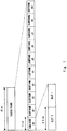
- Fig. 1 illustrates a radio frame structure in LTE and LTE-Advanced.
- 3GPP 3rd Generation Partnership Project
- frame structure type 1 and can be applied to frequency division duplex (FDD).
- frame structure type 2 and can be applied to time division duplex (TDD).
- FDD frequency division duplex
- TDD time division duplex
- the duration of one radio frame is 10 ms
- one radio frame consists of 10 subframes.
- the duration of one subframe is 1 ms.
- one subframe is divided into two slots of 0.5 ms each.
- Fig. 2A illustrates details of downlink time-frequency resources in LTE and LTE-Advanced.
- One downlink slot (0.5 ms) includes N DL SYMB orthogonal frequency-division multiplexing (OFDM) symbols in the time domain.
- a radio resource defined by one OFDM symbol in the time domain and one subcarrier in the frequency domain is referred to as a "resource element.”
- a resource element is the minimum unit of radio resources in the downlink of LTE and LTE-Advanced using ODFM.
- a resource unit defined by N DL SYMB consecutive OFDM symbols in the time domain and N RB SC consecutive subcarriers in the frequency domain is referred to as a "resource block.”
- the value of N DL SYMB is 7 and the value of N RB SC is 12 and, therefore, one downlink resource block consists of 84 resource elements.
- the occupied bandwidth i.e., N DL RB resource blocks or N DL RB N RB SC subcarriers
- the occupied bandwidth depends on the downlink system bandwidth (i.e., channel bandwidth (BW Channel )). For example, if the system bandwidth is 1.4 MHz, the maximum number of downlink resource blocks (N DL RB ) is 6, and if the system bandwidth is 20 MHz, the maximum number of downlink resource blocks (N DL RB ) is 100.
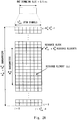
- Fig. 2B illustrates details of uplink time-frequency resources in LTE and LTE-Advanced.
- One uplink slot (0.5 ms) includes N UL SYMB single-carrier frequency-division multiple access (SC-FDMA) symbols in the time domain.
- SC-FDMA is also referred to as discrete Fourier transform (DFT)-spread OFDM (DFTS-OFDM).
- DFT discrete Fourier transform
- DFTS-OFDM discrete Fourier transform
- a radio resource defined by one SC-FDMA symbol in the time domain and one subcarrier in the frequency domain is referred to as a "resource element.”
- a resource element is the minimum unit of the radio resources in the uplink of LTE and LTE-Advanced using SC-FDMA.
- a resource unit defined by N UL SYMB consecutive SC-FDMA symbols in the time domain and N RB SC consecutive subcarriers in the frequency domain is referred to as a "resource block.”
- the value of N UL SYMB is 7 and the value of N RB SC is 12 and, therefore, one uplink resource block consists of 84 resource elements.
- the occupied bandwidth i.e., N UL RB resource blocks or N UL RB N RB SC subcarriers
- the occupied bandwidth depends on the uplink system bandwidth (i.e., channel bandwidth (BW Channel )). For example, if the system bandwidth is 1.4 MHz, the maximum number of uplink resource blocks (N UL RB ) is 6, and if the system bandwidth is 20 MHz, the maximum number of uplink resource blocks (N UL RB ) is 100.
- downlink user data is transmitted on a physical downlink shared channel (PDSCH).
- a wireless terminal i.e., user equipment (UE) receives downlink data on a PDSCH, checks whether a cyclic redundancy check (CRC) error is present in the downlink data, and transmits HARQ ACK/NACK bits indicating the result of CRC (i.e., acknowledgement (ACK) or negative ACK (NACK)) on a physical uplink control channel (PUCCH) or a physical uplink shared channel (PUSCH).
- CRC cyclic redundancy check
- PUCCH physical uplink control channel
- PUSCH physical uplink shared channel
- PUCCH formats 1a and 1b are defined for HARQ ACK/NACK transmission.
- the PUCCH format 1a is used to transmit 1-bit HARQ ACK/NACK
- the PUCCH format 1b is used to transmit 2-bit HARQ ACK/NACK.
- the number of HARQ ACK/NACK bits is determined in accordance with the number of codewords (i.e., 1 or 2) transmitted in the downlink transmission. In other words, the number of HARQ ACK/NACK bits is determined in accordance with whether spatial multiplexing is applied in the downlink transmission. When spatial multiplexing is applied, two codewords (i.e., two transport blocks) are transmitted in a single subframe, and thus the PUCCH format 1b is used.
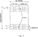
- the PUCCH is transmitted on the frequency ranges located at both ends of the system bandwidth.
- the PUCCH transmission in a single subframe is performed by using a single resource block in a first slot (0.5 ms) located at one end of the system bandwidth or in the vicinity thereof and a single resource block in a second slot (0.5 ms) located at the other end of the system bandwidth or in the vicinity thereof.
- These two resource blocks (RBs) are referred to as an RB pair.
- a plurality of RB pairs are used to increase the control signaling capacity.
- the RB pair (PUCCH region) to be used by the UE can be derived from a PUCCH resource index.
- the PUCCH resource index is configured in the UE by a base station (i.e., eNodeB (eNB)).
- CA carrier aggregation
- a wireless terminal is configured by a base station (eNB) with a plurality of carriers (referred to as component carriers (CCs)) at different frequencies, and can use these component carriers for uplink communication or downlink communication or both.
- CCs component carriers
- Release 10 specifies carrier aggregation of up to five CCs.
- the maximum system bandwidth of one CC is 20 MHz, and thus a wireless terminal can use up to 100 MHz in CA of 3GPP Release 10.
- a new ACK/NACK PUCCH format is defined in Release 10.
- This new ACK/NACK PUCCH format which is referred to as a PUCCH format 3, allows HARQ ACK/NACK transmission of up to 20 bits.
- the PUCCH format 3 is described, for example, in Section 5.4.2A of 3GPP TS 36.211 V12.5.0 (Non Patent Literature 1).
- Fig. 4 illustrates a HARQ ACK/NACK transmission scheme using the PUCCH format 3 when a normal cyclic prefix is used.
- error-correcting coding and rate matching for the HARQ ACK/NACK bits of a maximum of 20 bits, which have been generated through PDSCH reception are performed and coded ACK/NACK bits having a length of 48 bits are generated.
- the coded ACK/NACK bits are scrambled and then mapped to QPSK symbols, and thus 24 QPSK modulation symbols are generated (402).
- 12 modulation symbols (403) are transmitted in the first slot within a subframe
- the remaining 12 modulation symbols (404) are transmitted in the second slot within the subframe.
- Fig. 4 illustrates a process on the 12 modulation symbols (403) transmitted in the first slot.
- Block-wise spreading is performed on these 12 symbols (403). Specifically, the 12 modulation symbols corresponding to one SC-FDMA symbol are spread by the same length-5 spreading code sequence [w(0) (1) w(2) w(3) w(4)] (404 to 409). This spreading code sequence is also referred to as an orthogonal sequence or an orthogonal cover code (OCC) sequence.
- the time-domain spreading using the length-5 spreading code sequence provides five sets of 12 modulation symbols. These five sets of 12 modulation symbols are mapped to predetermined five SC-FDMA symbols within the first slot. Each set of 12 modulation symbols is cyclically shifted, DFT-spread, mapped to 12 subcarriers, and converted to a time-domain signal through Inverse Fast Fourier Transform (IFFT), and thus SC-FDMA symbols are generated.
- IFFT Inverse Fast Fourier Transform
- Non Patent Literature 1 3GPP TS 36.211 V12.5.0 (2015-03), "3rd Generation Partnership Project; Technical Specification Group Radio Access Network; Evolved Universal Terrestrial Radio Access (E-UTRA); Physical channels and modulation (Release 12),” March, 2015
- PUCCH physical uplink control channel
- more than one serving cells are configured to the terminal, and the more than one serving cells can include one PCell and at least one SCell.
- the acknowledgement information can be transmitted using a PUCCH format 1a/1b when one physical downlink shared channel (PDSCH) without a corresponding physical downlink control channel (PDCCH) detected, exists only on PCell in the downlink sub-frame set, and a semi-persistent scheduling (SPS) release PDCCH does not exist in the downlink sub-frame set.
- PDSCH physical downlink shared channel
- PDCCH physical downlink control channel
- a UE In the case of FDD, when CA of 32 DL component carriers (CCs) is performed and when a two-codeword transmission mode is used for each DL CC, a UE needs to transmit a total of 64-bit HARQ ACK/NACK in response to the DL reception on the 32 DL CCs. Furthermore, in the case of TDD, the number of HARQ ACK/NACK bits to be transmitted by the UE increases in proportion to the bundling window size. For example, when the situation of TDD is identical to that of the above-described FDD case and when the bundling window size is 2, the UE needs to transmit 128-bit HARQ ACK/NACK.
- the UE When the bundling window size is 4, the UE needs to transmit 256-bit HARQ ACK/NACK.
- the number of HARQ ACK/NACK bits is compressed to 1 bit per bundling window by a logical AND operation of all the HARQ ACK/NACK bits within the bundling windows.
- the number of HARQ ACK/NACK bits in TDD can be compressed only up to 64 bits. Therefore, a new PUCCH format in which the number of HARQ ACK/NACK bits that can be transmitted per subframe is greater than that in the exiting PUCCH format 3 is required.
- HARQ ACK/NACK bits that a UE can transmit per resource block (or per slot) or per subframe may result in an increase in the PUCCH resources (resource blocks) or a decrease in the number of UEs that can be multiplexed on the same PUCCH resource block, or both.
- the number of UEs (or the number of PUCCH transmissions) that can be multiplexed on the same resource block through time-domain spreading using orthogonal spreading codes may decrease.
- not all the UEs support CA of up to 32 CCs, and it is expected that the number of aggregated CCs differs among the UEs. Therefore, it is preferable that a new PUCCH format be able to adjust, depending on the number of component carriers, the number of HARQ ACK/NACK bits that a UE can transmit per unit time (e.g., slot or subframe).
- the present invention provides a wireless terminal apparatus, a base station apparatus, associated methods and programs as set out in the appended independent claims.
- Optional features are set out in the appended dependent claims. In the following, any examples and embodiments not falling within the scope of the claims do not form part of the invention and are provided for illustrative purposes only.
- a first aspect of the present invention provides a wireless terminal according to claim 1.
- a second aspect of the present invention provides a method in a wireless terminal according to claim 10.
- a third aspect of the present invention provides a wireless communication system according to claim 13.
- a fourth aspect of the present invention provides a method in a base station according to claim 14.
- a fifth aspect of the present invention provides a program according to claim 15.
- an apparatus, a method, and a program that contribute to making it possible to adjust, depending on the number of component carriers, the number of HARQ ACK/NACK bits that a UE can transmit per unit time (e.g., slot or subframe) can be provided.
- Embodiments described below will be described mainly using specific examples with regard to LTE, LTE-Advanced, and extensions thereof. However, these embodiments may also be applied to other wireless communication systems.
- Fig. 1 illustrates a configuration example of a wireless communication system according to some embodiments including the present embodiment.
- This wireless communication system provides communication services, such as voice communication or packet data communication or both.
- the wireless communication system includes a wireless terminal (UE) 1 and a base station (eNB) 2.
- UE wireless terminal
- eNB base station
- the wireless communication system is a system of 3GPP Release 8 and subsequent releases.
- the wireless terminal 1 corresponds to a UE
- the base station 2 corresponds to an eNB.
- the UE 1 and the eNB 2 support carrier aggregation of six or more component carriers.
- the UE 1 receives a DL signal(s) from the eNB on one or more DL component carriers (DL CCs) 501 and transmits a UL signal(s) to the eNB 2 on one or more UL component carriers (UL CCs) 502.
- DL CCs DL component carriers
- UL CCs UL component carriers
- the UE 1 transmits HARQ ACK/NACK bits corresponding to a plurality of DL CCs configured in the UE 1 on a single PUCCH on a single UL CC.
- the UE 1 is configured to change, depending on the number of DL CCs configured in the UE 1, the spreading rate to be applied to time-domain spreading of a plurality of modulation symbols generated from the HARQ ACK/NACK bits. It is to be noted that the number of HARQ ACK/NACK bits to be transmitted by the UE 1 on a single resource block (a single slot) or a single subframe is determined according to the number of DL CCs configured in the UE 1.
- the UE1 may be configured to change the spreading rate to be applied to the time-domain spreading (i.e., block-wise spreading) of ACK/NACK modulation symbols, depending on the number of HARQ ACK/NACK bits to be transmitted on a single PUCCH on a single UL CC.
- time-domain spreading i.e., block-wise spreading
- the UE 1 may reduce the spreading rate to be applied to the ACK/NACK modulation symbols as the number of DL CCs configured in the UE 1 increases. In other words, the UE 1 may increase the spreading rate to be applied to the HARQ ACK/NACK modulation symbols as the number of DL CCs configured in the UE 1 decreases. As the spreading rate decreases, the chip rate decreases and the number of ACK/NACK modulation symbols (the number of HARQ ACK/NACK bits) that one UE 1 can transmit per resource block increases, and accordingly the number of HARQ ACK/NACK bits that one UE 1 can transmit on a single resource block increases.
- the number of ACK/NACK modulation symbols (the number of HARQ ACK/NACK bits) that the UE 1 can transmit per resource block decreases, but the number of UEs that can be multiplexed on the same resource block can be increased.
- the eNB 2 is configured to receive a PUCCH transmitted from the UE 1 in accordance with a new PUCCH format.
- the new PUCCH format enables the UE 1, when HARQ ACK/NACK bits corresponding to a plurality of DL CCs configured in the UE 1 are transmitted on a single PUCCH on a single UL CC, to change the spreading rate applied to the time-domain spreading of modulation symbols generated from the HARQ ACK/NACK bits, depending on the number of the DL CCs or the number of the HARQ ACK/NACK bits.
- the UE 1 when HARQ ACK/NACK bits corresponding to DL CCs configured in the UE 1 are transmitted on a single PUCCH on a single UL CC, the UE 1 changes the spreading rate of the time-domain spreading (i.e., block-wise spreading) of ACK/NACK modulation symbols, depending on the number of the DL CCs or the number of the HARQ ACK/NACK bits. Therefore, the UE 1 can adjust the number of HARQ ACK/NACK bits that the UE 1 can transmit per unit time (e.g., per slot or per subframe), depending on the number of component carriers configured in the UE 1, without changing a PUCCH format.
- time-domain spreading i.e., block-wise spreading
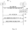
- Fig. 6 illustrates an example (process 600) of a communication procedure performed by the UE 1 and the eNB 2.
- the eNB 2 transmits one or more RRC signaling messages to the UE 1.
- the RRC signaling in block 601 may include, for example, an RRC Connection Setup message or may include one or more RRC Connection Reconfiguration messages.
- the RRC signaling in block 601 may include at least one RRC Connection Reconfiguration message to configure one or more secondary component carriers in the UE 1 for carrier aggregation.
- the UE 1 configures the UE 1 in accordance with the RRC signaling in block 601.
- the configuration in block 602 includes selecting, by the UE 1, a PUCCH format, a resource block(s) used to transmit a PUCCH (i.e., PUCCH resource), a spreading code sequence, and a spreading rate in order to transmit HARQ ACK/NACK bits, which correspond to the primary DL CC and one or more secondary DL CCs, on a PUCCH on the primary UL CC.
- the spreading code sequence and the spreading rate are to be applied to the block-wise spreading of HARQ ACK/NACK modulation symbols.
- the UE 1 selects the spreading rate to be applied to the block-wise spreading of HARQ ACK/NACK modulation symbols, depending on the number of CCs configured in the UE 1.
- Each of the PUCCH format, the PUCCH resource, the spreading code sequence, and the spreading rate may be indicated explicitly or implicitly by the eNB 2 in the RRC signaling in block 601.
- the eNB 2 may transmit, in block 601, RRC signaling indicating that the new PUCCH format described above is to be used.
- the eNB 2 may implicitly indicate the spreading rate to the UE 1.
- the eNB 2 may configure one or more secondary CCs in the UE 1 to implicitly indicate to the UE 1 the spreading rate to be applied to the block-wise spreading of HARQ ACK/NACK modulation symbols.
- the UE 1 may select the spreading rate based on the number of CCs configured in the UE 1.
- the eNB 2 may explicitly indicate the resource index for the new PUCCH format to the UE 1.
- the UE 1 may derive, from the resource index, the PUCCH resource (i.e., a RB pair used to the PUCCH transmission) and the sequence index indicating the spreading code sequence to be used.
- a part or all of the one or more secondary cells (SCells) configured in the UE 1 or, in other words, a part or all of the one or more secondary CCs (SCCs) are activated.
- the activation of these SCells (SCCs) may be performed by transmitting an activation/deactivation medium access control (MAC) control element (CE) from the eNB 2 to the UE 1.
- MAC medium access control
- the eNB 2 transmits data to the UE 1 on a plurality of DL CCs.
- the UE 1 in response to the data reception on the plurality of DL CCs, transmit HARQ ACK/NACK bits corresponding to the plurality of DL CCs on a single PUCCH on a single UL CC (e.g., the primary CC).
- the PUCCH format, the PUCCH resource, the spreading code sequence, and the spreading rate which have been selected in block 602 are used.
- Fig. 7 is a flowchart illustrating an example (process 700) of the operation performed by the UE 1.
- the UE 1 receives one or more RRC signaling messages from the eNB 2.
- the UE 1 selects a PUCCH format, a resource block(s) (i.e., PUCCH resource) used to transmit a PUCCH, a spreading code sequence, and a spreading rate, in accordance with the one or more RRC signaling messages in block 701.
- the spreading code sequence and the spreading rate are to be applied to the block-wise spreading of HARQ ACK/NACK modulation symbols.
- the UE 1 selects the spreading rate to be applied to the block-wise spreading of HARQ ACK/NACK modulation symbols, depending on the number of CCs configured in the UE 1.
- the UE 1 activates one or more SCells (SCCs) in accordance with an instruction from the eNB 2.
- the UE 1 receives data from the eNB 2 on a plurality of DL CCs.
- the UE 1 transmits HARQ ACK/NACK bits corresponding to these DL CCs to the eNB 2 on a single PUCCH on a single UL CC.
- the PUCCH format, the PUCCH resource, the spreading code sequence, and the spreading rate which have been selected in block 702 are used.
- Fig. 8 is a flowchart illustrating an example (process 800) of the operation performed by the eNB 2.
- the eNB 2 transmits one or more RRC signaling messages to the UE 1. This signaling explicitly or implicitly indicates to the UE 1 the PUCCH format and the spreading rate to be used by the UE 1. Here, the spreading rate is to be applied to the block-wise spreading of HARQ ACK/NACK modulation symbols.
- the eNB 2 activates a part or all of the one or more SCells (SCCs) configured in the UE 1.
- the eNB 2 transmits data to the UE 1 on a plurality of DL CCs.
- the eNB 2 receives from the UE 1, on a single PUCCH on a single UL CC, HARQ ACK/NACK bits corresponding to the plurality of DL CCs.
- the UE 1 is configured to selectively perform at least two of first, second, and third time-domain spreading operations on HARQ ACK/NACK modulation symbols, depending on the number of the DL CCs (or the number of the HARQ ACK/NACK bits) configured in the UE 1.
- the first, second, and third time-domain spreading operations are as follows.
- the first time-domain spreading operation includes performing time-domain spreading on a single data block at a spreading rate of 2n (n is an integer) by using a first length-2n spreading code sequence.
- the single data block is to be mapped to predetermined 2n single-carrier FDMA (SC-FDMA) symbols within a single slot in accordance with the PUCCH format used to transmit the plurality of HARQ ACK/NACK bits.
- SC-FDMA 2n single-carrier FDMA
- the second time-domain spreading operation includes performing time-domain spreading on two data blocks at a spreading rate of n by using a second length-n spreading code sequence and a third length-n spreading code sequence.
- the second spreading code sequence consists of n elements of the first spreading code sequence described above
- the third spreading code sequence consists of the remaining n elements of the first spreading code sequence described above.
- the two data blocks are to be mapped to the same predetermined 2n SC-FDMA symbols within the same slot as in the case of the first time-domain spreading, in accordance with the PUCCH format.
- the third time-domain spreading operation includes performing time-domain spreading on 2n data blocks at a spreading rate of 1 by using 2n length-1 spreading code sequences.
- the 2n spreading code sequences each consists of a respective one of the 2n elements of the first spreading code sequence described above.
- the 2n data blocks are to be mapped to the same predetermined 2n SC-FDMA symbols within the same predetermined slot as in the case of the first and second time-domain spreading operations, in accordance with the PUCCH format.
- each data block corresponds to the HARQ ACK/NACK modulation symbols to be subjected to the block-wise spreading.
- each data block includes 12 ACK/NACK modulation symbols, the number of which is equal to the number of subcarriers in one resource block.
- the first spreading code sequence may be determined by the UE 1 based on the resource index provided to the UE 1 by the eNB 2.
- the UE 1 may derive, from the resource index provided by the eNB 2, the sequence index indicating the spreading code sequence to be used.
- the first length-2n spreading code sequence is one of 2n spreading code sequences that are orthogonal to each other.
- the spreading code sequences (or orthogonal code sequences) excluding the first spreading code sequence are used by other UEs.
- the first spreading code sequence and at least one other spreading code sequence (hereinafter referred to as a fourth spreading code sequence) included in the 2n (orthogonal) spreading code sequences may be defined as follows.
- the second spreading code sequence, which is a subset of the first spreading code sequence, is orthogonal to a spreading code sequence consisting of corresponding two elements of the fourth spreading code sequence
- the third spreading code sequence, which is the remaining subset of the first spreading code sequence is orthogonal to a spreading code sequence consisting of the remaining two elements of the fourth spreading code sequence.
- the set of the spreading code sequences that includes the first and fourth spreading code sequences defined as above makes it possible to multiplex the PUCCH transmissions of multiple users (i.e., UEs 1) using different spreading rates on the same resource block, which will be described in detail below.
- n spreading code sequences that is, four spreading code sequences may be defined as shown in Table 1 below.
- Table 1 SEQUENCE INDEX n oc ORTHOGONAL SEQUENCE OF LENGTH 4 [w n oc (0) w n oc (1) w n oc (2) w n oc (3)] 0 [+1 +1 +1 +1] 1 [+1 +1 -1 -1] 2 [+1 -1 +1 -1] 3 [+1 -1 -1 +1]
- the four spreading code sequences w 0 (i) to w 3 (i) shown in Table 1 are orthogonal to one another. Furthermore, the following relationship holds between the spreading code sequences w 0 (i) and w 2 (i).
- the relationship similar to that between the pair of the spreading code sequences w 0 (i) and w 2 (i) also holds between a pair of the spreading code sequences w 0 (i) and w 3 (i), between a pair of the spreading code sequences w 1 (i) and w 2 (i), and between a pair of the spreading code sequences w 1 (i) and w 3 (i).
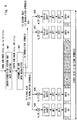
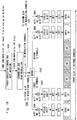
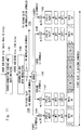
- Figs. 9 , 10 and 11 illustrate three specific examples of a transmission scheme using the new PUCCH format according to the present embodiment and correspond respectively to the first, second, and third time-domain spreading operations described above.
- the UE 1 performs the time-domain spreading (block-wise spreading) on a single data block (i.e., 12 ACK/NACK modulation symbols in this case) at a spreading rate of 4 by using any one of the length-4 spreading code sequences w 0 (i) to w 3 (i).
- This single data block i.e., 12 ACK/NACK modulation symbols
- the predetermined four SC-FDMA symbols are the first, second, sixth, and seventh SC-FDMA symbols among the seven SC-FDMA symbols within the single slot.
- the third, fourth, and fifth SC-FDMA symbols are used to transmit a reference signal (RS).
- RS reference signal
- the transmission scheme illustrated in Fig. 9 is used when the number of HARQ ACK/NACK bits to be transmitted in a single subframe is no greater than 16, for example.
- the processes in blocks 901 and 902 are similar to those in block 401 and 402 in the transmission scheme for the PUCCH format 3 illustrated in Fig. 4 .
- block 901 error-correcting coding and rate matching for the HARQ ACK/NACK bits (up to 16 bits) corresponding to the data reception on a plurality of DL CCs are performed, and coded ACK/NACK bits having a length of 48 bits are generated.
- the coded ACK/NACK bits are scrambled and then mapped to QPSK modulation symbols, and thus 24 modulation symbols are generated (902).
- Fig. 9 illustrates a process on the 12 modulation symbols (903) transmitted in the first slot.
- Block-wise spreading is performed on these 12 modulation symbols (903). Specifically, the 12 modulation symbols corresponding to one SC-FDMA symbol are spread by a spreading code sequence [w k (0) w k (1) w k (2) w k (3)] which is one of the four length-4 spreading code sequences shown in Table 1 (904 to 908). Thus, four sets of 12 modulation symbols are obtained. These four sets of 12 modulation symbols are mapped to the predetermined four SC-FDMA symbols within the first slot. Each set of 12 modulation symbols are cyclically shifted, DFT-spread, mapped to 12 subcarriers, and converted to a time-domain signal through IFFT, and thus SC-FDMA symbols are generated.
- the example illustrated in Fig. 10 corresponds to the second time-domain spreading operation described above.
- the UE 1 performs the time-domain spreading (block-wise spreading) on two data blocks at a spreading rate of 2 by using a length-2 spreading code sequence [w k (0) w k (1)] and a length-2 spreading code sequence [w k (2) w k (3)].
- the spreading code sequence [w k (0) w k (1)] consists of the first and second elements of a spreading code sequence [w k (0) w k (1) w k (2) w k (3)] which is one of the four length-4 spreading code sequences shown in Table 1, and the spreading code sequence [w k (2) w k (3)] consists of the remaining third and fourth elements of it.
- the two data blocks are two sets of 12 ACK/NACK modulation symbols. These two data blocks are mapped to the predetermined four SC-FDMA symbols within the same slot as in the case of the example illustrated in Fig. 9 (i.e., first time-domain spreading operation) in accordance with the PUCCH format.
- the transmission scheme illustrated in Fig. 10 is used when the number of HARQ ACK/NACK bits to be transmitted in a single subframe is within a range of from 17 to 32.
- block 1001 error-correcting coding and rate matching for the HARQ ACK/NACK bits (up to 32 bits) corresponding to the data reception on a plurality of DL CCs are performed, and coded ACK/NACK bits having a length of 96 bits are generated.
- the coded ACK/NACK bits are scrambled and then mapped to QPSK symbols, and thus 48 QPSK modulation symbols are generated (1002).
- Fig. 10 illustrates a process on the 24 modulation symbols (1003) transmitted in the first slot.
- These 24 modulation symbols (1003) are divided into two sets each consisting of 12 modulation symbols (1005). Then, these two sets are subjected to block-wise spreading using the length-2 spreading code sequences [w k (0) w k (1)] and [w k (2) w k (3)], respectively. Specifically, the first 12 modulation symbols of the 24 modulation symbols (1003) are spread by the length-2 spreading code sequence [w k (0) w k (1)] (1006, 1007) and are arranged to the first and second SC-FDMA symbols through cyclic shift, DFT-spreading, and IFFT.
- the remaining 12 modulation symbols are spread by the length-2 spreading code sequence [w k (2) w k (3)] (1008, 1009) and are arranged to the sixth and seventh SC-FDMA symbols through cyclic shift, DFT-spreading, and IFFT.
- the example illustrated in Fig. 11 corresponds to the third time-domain spreading operation described above.
- the UE 1 performs the time-domain spreading on four data blocks at a spreading rate of 1 by using four length-1 spreading code sequences each consisting of a respective one of the first to fourth elements of a spreading code sequence [w k (0) w k (1) w k (2) w k (3)] which is one of the four length-4 spreading code sequences shown in Table 1.
- the four data blocks are four sets of 12 ACK/NACK modulation symbols. These four data blocks are mapped to the predetermined four SC-FDMA symbols within the same slot as in the case of the example illustrated in Fig. 9 (i.e., first time-domain spreading operation) in accordance with the PUCCH format.
- the transmission scheme illustrated in Fig. 11 is used when the number of HARQ ACK/NACK bits to be transmitted in a single subframe exceeds 32.
- block 1101 error-correcting coding and rate matching for the HARQ ACK/NACK bits of equal to or longer than 33 bits corresponding to the data reception on a plurality of DL CCs are performed, and coded ACK/NACK bits having a length of 192 bits are generated.
- the coded ACK/NACK bits are scrambled and then mapped to QPSK symbols, and thus 96 QPSK modulation symbols are generated (1102).
- Fig. 11 illustrates a process on the 48 modulation symbols (1103) transmitted in the first slot.
- These 48 modulation symbols (1103) are divided into four sets each consisting of 12 modulation symbols (1105). Then, these four sets are subjected to block-wise spreading using the length-1 spreading code sequences [w k (0)], [w k (1)], [w k (2)], and [w k (3)], respectively. Specifically, the first 12 modulation symbols of the 48 modulation symbols (1103) are spread by the length-1 spreading code sequence [w k (0)] (1106) and are arranged to the first SC-FDMA symbol through cyclic shift, DFT-spreading, and IFFT.
- the second 12 modulation symbols of the 48 modulation symbols (1103) are spread by the length-1 spreading code sequence [w k (1)] (1107) and are arranged to the second SC-FDMA symbol through cyclic shift, DFT-spreading, and IFFT.
- the third 12 modulation symbols of the 48 modulation symbols (1103) are spread by the length-1 spreading code sequence [w k (2)] (1108) and are arranged to the sixth SC-FDMA symbol through cyclic shift, DFT-spreading, and IFFT.
- the fourth 12 modulation symbols of the 48 modulation symbols (1103) are spread by the length-1 spreading code sequence [w k (3)] (1109) and are arranged to the seventh SC-FDMA symbol through cyclic shift, DFT-spreading, and IFFT.
- the UE 1 can change the spreading rate of the time-domain spreading (i.e., block-wise spreading) of ACK/NACK modulation symbols, depending on the number of the DL CCs or the number of the HARQ ACK/NACK bits.
- multiple users i.e., UEs 1
- multiple UEs 1 using different spreading rates for the time-domain spreading on the ACK/NACK modulation symbols can be multiplexed on the same resource block.
- two UEs 1 following the transmission scheme illustrated in Fig. 9 and one UE 1 following the transmission scheme illustrated in Fig. 10 can transmit their PUCCHs on the same resource block.
- the relationship similar to that between the pair of the spreading code sequences w 0 (i) and w 2 (i) also holds between a pair of the spreading code sequences w 0 (i) and w 3 (i), between a pair of the spreading code sequences w 1 (i) and w 2 (i), and between a pair of the spreading code sequences w 1 (i) and w 3 (i). Therefore, the PUCCH transmission at a spreading rate of 4 that follows the transmission scheme illustrated in Fig. 9 and the PUCCH transmission at a spreading rate of 2 that follows the transmission scheme illustrated in Fig. 10 can be multiplexed on the same resource block since the interference therebetween is suppressed due to the orthogonality of the spreading code sequences.
- the four length-4 spreading code sequences shown in Table 1 may be assigned to the users (i.e., UEs 1) as shown in Table 2.
- “#bit” represents the number of HARQ ACK/NAK bits to be transmitted by each user in one subframe.
- "CODE #0,” “CODE #1,” “CODE #2,” and “CODE #3” in the table represent respectively the four spreading code sequences (i.e., orthogonal sequences) w 0 (i), w 1 (i), w 2 (i), and w 3 (i) shown in Table 1.
- Table 2 is merely an example.
- USER #0 may use any one of CODE #0 to CODE #4.
- USER #0 may use CODE #1 instead of CODE #0, and USER #1 may use CODE #3 instead of CODE #2.
- USER #0 may use CODE #2 or CODE #3, USER #1 may use CODE #0, and USER #2 may use CODE #1.
- the set of the spreading code sequences shown in Table 1 is merely an example. Another set having orthogonality similar to that of the set of the spreading code sequences shown in Table 1 may instead be used.
- the arrangement of the four data symbols #1 to #4 and the three RS symbols in the seven SC-FDMA symbols within a single slot is an example.
- the arrangement of the data symbols and the RS symbols within a single slot may be modified as described later in a second embodiment, for example.
- each UE 1 transmits a PUCCH in accordance with a PUCCH format and a transmission scheme similar to those of the first embodiment.
- HARQ ACK/NACK modulation symbols are arranged in SC-FMDA symbols other than the last SC-FDMA symbol (i.e., the seventh SC-FDMA symbol) within each slot.
- the last SC-FDMA symbol (the seventh SC-FDMA symbol) within each slot may be used to transmit a reference signal (RS) symbol.
- RS reference signal
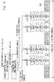
- Figs. 12 , 13 and 14 illustrate three specific examples of a transmission scheme in accordance with the PUCCH format according to the present embodiment.
- Figs. 12 , 13 and 14 correspond respectively to Figs. 9 , 10 and 11 described in the first embodiment and are identical to Figs. 9 , 10 and 11 except in the arrangement of the four data symbols #1 to #4 and the three RS symbols.
- each of the last SC-FDMA symbols 1201, 1301, and 1401 within the slot is not used to transmit ACK/NACK modulation symbols but used to transmit an RS symbol.
- each UE is required to transmit a sounding reference signal (SRS) periodically at the transmission interval configured by the eNB.
- SRS is time-multiplexed on the position of the last SC-FDMA symbol in a subframe in which the SRS is transmitted. Therefore, when transmitting HARQ ACK/NACK in accordance with the exiting PUCCH format 1a/ab or 3, the UE 1 uses shortened PUCCH transmission in the SRS transmission subframes, and thus the last SC-FDMA symbol of the ACK/NACK (i.e., the last symbol within the second slot of the subframe) is not transmitted. The UE 1 refrains from transmitting a PUCCH with an SRS, and thus the single-carrier property or nature can be retained.
- SRS sounding reference signal
- the UE 1 uses a transmission format in which the length of the orthogonal spreading code sequence for the time-domain spreading is reduced by one, and thus the last PUCCH symbol is punctured.
- a transmission format is known as a shortened PUCCH format.
- the UE uses length-4 Walsh-Hadamard codes in place of length-5 DFT spreading codes.
- the PUCCH symbol arranged in the last SC-FDMA symbol in the second slot needs to be punctured.
- the UE 1 has to use length-3 DFT spreading codes in place of the length-4 Walsh-Hadamard codes as shown in Table 1.
- length-3 spreading codes i.e., spreading codes having a length of an odd number
- the UE 1 can use the length-4 Walsh-Hadamard codes also in the shortened PUCCH transmission (or shortened PUCCH format). Therefore, the PUCCH transmissions of UEs 1 using different spreading rates can be multiplexed on the same resource block in the SRS transmission subframe as well.
- RS symbol i.e., demodulation RS (DMRS) symbol
- DMRS demodulation RS
- the RS (DMRS) symbols are not subjected to spreading codes (orthogonal codes, OCCs) for the time-domain spreading, but RSs of a plurality UEs are multiplexed with different cyclic shifts. Therefore, even if the RS (DMRS) symbols are punctured, no problem arises in the orthogonality among the plurality of UEs 1.
- a UE 1 is configured to adjust the transmission power of a PUCCH depending on whether a sounding reference signal (SRS) is transmitted in a slot.
- the adjustment of the transmission power of the PUCCH depending on the presence of the SRS transmission may be performed by adding an offset ⁇ ShortFormat to the transmission power of the PUCCH when the SRS is transmitted.
- the eNB 2 may transmit a signaling message indicating the offset ⁇ ShortFormat to the UE 1.
- the transmission power of PUCCH can be adjusted depending on whether a sounding reference signal (SRS) is transmitted in a slot.
- SRS sounding reference signal
- the RS (DMRS) symbol arranged in the last SC-FDMA symbol in the second slot is punctured for the shortened PUCCH transmission. Due to the decrease in the number of RS (DMRS) symbols, the reception performance of the PUCCH in the eNB 2 may be degraded.
- the UE 1 may add the offset ⁇ ShortFormat to the transmission power of the PUCCH in the slot in which the RS (DMRS) symbol is punctured in order to transmit an SRS. In this way, the degradation of the PUCCH reception performance due to the puncture of the RS (DMRS) symbols can be compensated.
- ⁇ ShortFormat is an offset added to a normal value and is configured by higher layers.
- the offset ⁇ ShortFormat is configured for each PUCCH format. In this way, the performance can be tuned for each PUCCH format.
- the offset ⁇ ShortFormat (or ⁇ ShortFormat (F")) may be configured in the UE 1 by the eNB 2.
- Fig. 15 illustrates an example (process 1500) of a signaling procedure for configuring the offset ⁇ ShortFormat (or ⁇ ShortFormat (F")) in the UE 1.
- the eNB 2 transmits RRC signaling including the offset ⁇ ShortFormat (or ⁇ ShortFormat (F")) to the UE 1.
- This RRC signaling may be, for example, an RRC Connection Setup message or an RRC Connection Reconfiguration message.
- Fig. 16 illustrates a specific example of an information element transmitted to the UE 1 from the eNB 2 to configure the offset ⁇ ShortFormat in the UE 1.
- This information element may be defined as one of UplinkPowerControl information elements (IEs).
- This information element may be included in UplinkPowerControlDedicated IE or UplinkPowerControlCommon IE.
- the offset ⁇ ShortFormat is configured only for the new PUCCH format (referred to as "PUCCH format 4", herein).
- the items "dB0,” “dB1,” “dB2,” and “dB3" mean that the offset value is 0 dB, 1 dB, 2 dB, and 3 dB, respectively.
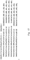
- Fig. 17 illustrates another specific example of an information element transmitted to the UE 1 from the eNB 2 to configure the offset ⁇ ShortFormat (F") in the UE 1.
- This information element may be defined as one of UplinkPowerControl information elements (IEs).
- IEs UplinkPowerControl Information elements
- This information element may be included in UplinkPowerControlDedicated IE or UplinkPowerControlCommon IE.
- the offset ⁇ ShortFormat is configured individually for all the PUCCH formats including the new PUCCH format (referred to as "PUCCH format 4", herein).
- the offset values indicated in the examples illustrated in Figs. 16 and 17 are merely examples.
- the number of the candidates for the offset value need not be four and may be no more than three or no less than five.
- different sets of candidates for the offset value may be configured for the different PUCCH formats.
- a UE 1 is configured to adjust the transmission power of a PUCCH depending on the spreading rate of the time-domain spreading (i.e., block-wise spreading) applied to HARQ ACK/NACK modulation symbols.
- the adjustment of the transmission power of the PUCCH depending on the spreading rate may be performed by adding, to the transmission power of the PUCCH, an offset ⁇ F_PUCCH (F) corresponding to the spreading rate.
- the eNB 2 may transmit a signaling message indicating the offset ⁇ F_PUCCH (F) to the UE 1.
- the offset ⁇ F_PUCCH (F) may be configured for each spreading rate by using the expression (1), the expression (2), or the expression (3) described above.
- the offset ⁇ F_PUCCH (F) for each spreading rate may be configured in the UE 1 by the eNB 2.
- Fig. 18 illustrates an example (process 1800) of a signaling procedure for configuring the offset ⁇ F_PUCCH (F) for each spreading rate in the UE 1.
- the eNB 2 transmits RRC signaling including the offset ⁇ F_PUCCH (F) for each spreading rate to the UE 1.
- This RRC signaling may be, for example, an RRC Connection Setup message or an RRC Connection Reconfiguration message.
- Fig. 19 illustrates a specific example of an information element transmitted to the UE 1 from the eNB 2 to configure the offset ⁇ F_PUCCH (F) for each spreading rate in the UE 1.
- This information element may be defined as one of UplinkPowerControl information elements (IEs).
- This information element may be included in UplinkPowerControlDedicated IE or UplinkPowerControlCommon IE.
- the item “deltaF-PUCCH-Format4-SF1" indicates the offset when the spreading rate is 1 in the new PUCCH format (referred to as "PUCCH format 4", herein).
- PUCCH format 4" new PUCCH format
- deltaF-1 means that the offset values are -1 dB, 0 dB, and 3 dB, respectively.
- the minimum value and the maximum value of the offset candidate are set greater.
- the gain obtained by the de-spreading process at the receiver side i.e., spreading gain
- the degradation in the reception performance resulting from a small spreading gain can be compensated by allowing a greater offset value (i.e., greater PUCCH transmission power) as the spreading rate decreases.
- Fig. 20 is a block diagram illustrating a configuration example of the UE 1.
- a radio frequency (RF) transceiver 2001 performs analog RF signal processing to communicate with the eNB 2.
- the analog RF signal processing performed by the RF transceiver 2001 includes frequency up-conversion, frequency down-conversion, and amplification.
- the RF transceiver 2001 is coupled to an antenna 2002 and a baseband processor 2003.
- the RF transceiver 2001 receives modulated symbol data (or OFDM symbol data) from the baseband processor 2003, generates a transmission RF signal, and supplies the transmission RF signal to the antenna 2002.
- the RF transceiver 2001 generates a baseband reception signal based on a reception RF signal received by the antenna 2002 and supplies the baseband reception signal to the baseband processor 2003.
- the baseband processor 2003 performs digital baseband signal processing (i.e., data plane processing) and control plane processing for wireless communication.
- the digital baseband signal processing includes (a) data compression/decompression, (b) segmentation/concatenation, (c) composition/decomposition of a transmission format (i.e., transmission frame), (d) channel coding/decoding, (e) modulation (i.e., symbol mapping)/demodulation, and (f) generation of OFDM symbol data (i.e., baseband OFDM signal) by Inverse Fast Fourier Transform (IFFT).
- IFFT Inverse Fast Fourier Transform
- control plane processing includes communication management of layer 1 (e.g., transmission power control), layer 2 (e.g., radio resource management and hybrid automatic repeat request (HARQ) processing), and layer 3 (e.g., signalling regarding attach, mobility, and call management).
- layer 1 e.g., transmission power control
- layer 2 e.g., radio resource management and hybrid automatic repeat request (HARQ) processing
- layer 3 e.g., signalling regarding attach, mobility, and call management.
- the digital baseband signal processing performed by the baseband processor 2003 may include signal processing of a packet data convergence protocol (PDCP) layer, a radio link control (RLC) layer, a MAC layer, and a PHY layer.
- PDCP packet data convergence protocol
- RLC radio link control
- MAC media access control
- PHY physical layer
- control plane processing performed by the baseband processor 2003 may include processing of a non-access stratum (NAS) protocol, an RRC protocol, and MAC CEs.
- NAS non-access stratum
- the baseband processor 2003 may include a modem processor (e.g., digital signal processor (DSP)) that performs the digital baseband signal processing and a protocol stack processor (e.g., central processing unit (CPU) or micro processing unit (MPU)) that performs the control plane processing.
- DSP digital signal processor
- protocol stack processor e.g., central processing unit (CPU) or micro processing unit (MPU)
- the protocol stack processor that performs the control plane processing may be integrated with an application processor 2004 described in the following.
- the application processor 2004 is also referred to as a CPU, an MPU, a microprocessor, or a processor core.
- the application processor 2004 may include a plurality of processors (processor cores).
- the application processor 2004 loads a system software program (Operating System (OS)) and various application programs (e.g., phone call application, WEB browser, mailer, camera operation application, and music player application) from a memory 2006 or another memory (not illustrated) and executes these programs, thereby providing various functions of the UE 1.
- OS Operating System
- application programs e.g., phone call application, WEB browser, mailer, camera operation application, and music player application
- the baseband processor 2003 and the application processor 2004 may be integrated on a single chip as represented by a dashed line (2005) in Fig. 20 .
- the baseband processor 2003 and the application processor 2004 may be implemented in a single System on Chip (SoC) device 2005.
- SoC System on Chip
- the SoC device may also referred to as a system large-scale integration (LSI) or a chip set.
- the memory 2006 is a volatile memory, a non-volatile memory, or a combination thereof.
- the memory 2006 may include a plurality of physically independent memory devices.
- the volatile memory is, for example, a static random-access memory (SRAM), a dynamic RAM (DRAM), or a combination thereof.
- the non-volatile memory is a mask read-only memory (MROM), an electrically erasable programmable ROM (EEPROM), a flash memory, a hard disk drive, or any combination thereof.
- the memory 2006 may include, for example, an external memory device accessible from the baseband processor 2003, the application processor 2004, and the SoC 2005.
- the memory 2006 may include a built-in memory device integrated within the baseband processor 2003, the application processor 2004, or the SoC 2005.
- the memory 2006 may include a memory within a universal integrated circuit card (UICC).
- UICC universal integrated circuit card
- the memory 2006 may store a software module(s) (computer program(s)) including instructions and data for performing the processing of the UE 1 described in the embodiments described above.
- the baseband processor 2003 or the application processor 2004 may be configured to load this software module(s) from the memory 2006 and executes the loaded software module(s), thereby performing the process of the UE 1 described in the above-described embodiments.
- Fig. 21 is a block diagram illustrating a configuration example of the eNB 2 according to the embodiments described above.
- the eNB 2 includes an RF transceiver 2101, a network interface 2103, a processor 2104, and a memory 2105.
- the RF transceiver 2101 performs analog RF signal processing to communicate with the UE 1.
- the RF transceiver 2101 may include a plurality of transceivers.
- the RF transceiver 2101 is coupled to an antenna 2102 and the processor 2104.
- the RF transceiver 2101 receives modulated symbol data (or OFDM symbol data) from the processor 2104, generates a transmission RF signal, and supplies the transmission RF signal to the antenna 2102.
- the RF transceiver 2101 generates a baseband reception signal based on a reception RF signal received by the antenna 2102 and supplies the baseband reception signal to the processor 2104.
- the network interface 2103 is used to communicate with a network node(s) (e.g., mobility management entity (MME) and serving gateway (S-GW)).
- the network interface 2103 may include, for example, a network interface card (NIC) conforming to the IEEE 802.3 series.
- the processor 2104 performs digital baseband signal processing (i.e., data plane processing) and control plane processing for wireless communication.
- digital baseband signal processing i.e., data plane processing
- control plane processing for wireless communication.
- the digital baseband signal processing performed by the baseband processor 2104 may include signal processing of the PDCP layer, the RLC layer, the MAC layer, and the PHY layer.
- the control plane processing performed by the baseband processor 2104 may include processing of the S1 protocol, the RRC protocol, and the MAC CEs.
- the processor 2104 may include a plurality of processors.
- the processor 2104 may include, for example, a modem processor (e.g., DSP) that performs the digital baseband signal processing and a protocol stack processor (e.g., CPU or MPU) that performs the control plane processing.
- a modem processor e.g., DSP
- a protocol stack processor e.g., CPU or MPU
- the memory 2105 is composed of a combination of a volatile memory and a non-volatile memory.
- the volatile memory is, for example, an SRAM, a DRAM, or a combination thereof.
- the non-volatile memory is, for example, an MROM, a PROM, a flash memory, a hard disk drive, or any combination thereof.
- the memory 2105 may include a storage disposed separately from the processor 2104. In this case, the processor 2104 may access the memory 2105 via the network interface 2103 or an I/O interface (not illustrated).
- the memory 2105 may store a software module(s) (computer program(s)) including instructions and data for performing the processing of the eNB 2 described in the embodiments described above.
- the processor 2104 may be configured to load this software module(s) from the memory 2105 and execute the loaded software module(s), thereby performing the processing of the eNB 2 described in the aforementioned embodiments.
- each of the processors included in the UE 1 and the eNB 2 executes one or more programs that include instructions for causing a computer to execute the algorithms described with reference to the drawings.
- These programs can be stored and provided to a computer by using a variety of types of non-transitory computer-readable media.
- the non-transitory computer-readable media include a variety of types of tangible storage media.
- non-transitory computer-readable media examples include a magnetic storage medium (e.g., flexible disk, magnetic tape, hard disk drive), an optical magnetic storage medium (e.g., magneto-optical disk), a compact disc read-only memory (CD-ROM), a CD-R, a CD-R/W, and a semiconductor memory (e.g., mask ROM, programmable ROM (PROM), erasable PROM (EPROM), flash ROM, random-access memory (RAM)).
- the programs may be supplied to a computer in the form of a variety of types of transitory computer-readable media. Examples of the transitory computer-readable media include an electric signal, an optical signal, and an electromagnetic wave.
- a transitory computer-readable medium can provide the programs to a computer via a wired communication line, such as an electric wire and an optical fiber, or via a wireless communication line.
- different spreading code sequences may be applied in a first slot and a second slot within a single subframe.
- the cell (CC) in which a PUCCH is transmitted is not limited to a primary cell (PCell) (i.e., primary component carrier (PCC)) in carrier aggregation.
- PCell i.e., primary component carrier (PCC)
- PUCCH primary component carrier
- the embodiments may be modified such that a PUCCH is configured in any SCell and HARQ ACK/NACK regarding DL transmission on a plurality of SCells is transmitted on the PUCCH of the aforementioned SCell.
- the embodiments described above may be applied to carrier aggregation of a master cell group (MCG) in dual connectivity or may be applied to carrier aggregation of a secondary cell group (SCG) in dual connectivity.
- the PCell (PCC) of the carrier aggregation may be considered to correspond to a primary SCell (PSCell).
- the PSCell is a special SCell in the SCG provided by a secondary eNB (SeNB).
- the PSCell is configured with a PUCCH and is never deactivated, and a RACH procedure is required for the initial configuration of the PSCell.
- the method described in the third embodiment which includes adjusting the transmission power of a PUCCH in a subframe depending on whether a sounding reference signal (SRS) is transmitted in the subframe, may be implemented independently from the improvement of the PUCCH format (i.e., the change in the spreading rate depending on the number of CCs) described in the first and second embodiments.
- the method may be applied to the transmission using the existing PUCCH formats 1a/1b and 3.
- a wireless terminal includes:
- the adjustment of the transmission power of the PUCCH may be performed by adding a first offset to the transmission power of the PUCCH when the SRS is transmitted in the slot in which the PUCCH is transmitted.
- the at least one processor may be configured to receive a signaling message indicating the first offset from the base station.
- the last PUCCH symbol arranged in the last SC-FDMA symbol in the second slot is punctured for the shortened PUCCH transmission.
- the spreading rate applied to the transmission of HARQ ACK/NACK modulation symbols in the slot in which an SRS is transmitted is smaller than the spreading rate in the slot in which an SRS is not transmitted.
- the spreading gain of the PUCCH in the slot in which an SRS is transmitted is smaller than the spreading gain in the slot in which an SRS is not transmitted.
- the decrease in the spreading gain at the time of the shortened PUCCH transmission can be compensated by using the method of adjusting the PUCCH transmission power, which is described in the third embodiment, in the transmission schemes of the exiting PUCCH formats 1a/1b and 3.
Landscapes
- Engineering & Computer Science (AREA)
- Signal Processing (AREA)
- Computer Networks & Wireless Communication (AREA)
- Quality & Reliability (AREA)
- Physics & Mathematics (AREA)
- Spectroscopy & Molecular Physics (AREA)
- Power Engineering (AREA)
- Mobile Radio Communication Systems (AREA)
Claims (15)
- Drahtlosendgerät (1) mit:einem Drahtlostransceiver (2001), der dafür konfiguriert ist, drahtlos mit einer Basisstation (2) zu kommunizieren; undmindestens einem Prozessor (2003), der mit dem Drahtlostransceiver (2001) verbunden ist, wobeider mindestens eine Prozessor (2003) dafür konfiguriert ist, wenn mehrere HARQ-, Hybrid Automatic Repeat Request, ACK/NACK-Bits, die mehreren Downlink-Komponententrägern, DL-CCs, entsprechen, die im Drahtlosendgerät (1) konfiguriert sind, über einen einzelnen physikalischen Uplink-Steuerkanal, PUCCH, auf einem einzelnen Uplink-Komponententräger, UL-CC, übertragen werden, in Abhängigkeit von der Anzahl der mehreren DL-CCs oder der Anzahl der mehreren HARQ-ACK/NACK-Bits eine Spreizrate zu ändern, die auf eine Zeitbereich-Spreizung mehrerer Modulationssymbole angewendet werden soll, die von den mehreren HARQ-ACK/NACK-Bits erzeugt werden, dadurch gekennzeichnet, dass:der mindestens eine Prozessor (2003) dafür konfiguriert ist, selektiv mehrere Zeitbereich-Spreizoperationen, einschließlich einer ersten und einer zweiten Zeitbereich-Spreizoperation, zum Ändern der Spreizrate in Abhängigkeit von der Anzahl der mehreren DL-CCs oder der Anzahl der mehreren HARQ-ACK/NACK-Bits auszuführen,die erste Zeitbereich-Spreizoperation das Ausführen einer Zeitbereich-Spreizung bezüglich eines einzelnen Datenblocks mit einer Spreizrate von 2n unter Verwendung einer ersten Spreizcodesequenz der Länge 2n beinhaltet, wobei der einzelne Datenblock auf vorgegebene 2n Einzelträger-FDMA, SC-FDMA, Symbole innerhalb eines einzelnen Slots gemäß einem PUCCH-Format abgebildet werden soll, das zum Übertragen der mehreren HARQ-ACK/NACK-Bits verwendet wird, unddie zweite Zeitbereich-Spreizoperation das Ausführen einer Zeitbereich-Spreizung bezüglich zwei Datenblöcken mit einer Spreizrate von n unter Verwendung einer zweiten Spreizcodesequenz der Länge n, die aus n Elementen der ersten Spreizcodesequenz besteht, und einer dritten Spreizcodesequenz der Länge n beinhaltet, die aus den verbleibenden n Elementen der ersten Spreizcodesequenz besteht, wobei die zwei Datenblöcke auf die vorgegebenen 2n SC-FDMA-Symbole innerhalb des einzelnen Slots gemäß dem PUCCH-Format abgebildet werden sollen.
- Drahtlosendgerät (1) nach Anspruch 1, wobei
die mehreren Zeitbereich-Spreizoperationen ferner eine dritte Zeitbereich-Spreizoperation aufweisen und die dritte Zeitbereich-Spreizoperation das Ausführen einer Zeitbereich-Spreizung bezüglich 2n Datenblöcken mit einer Spreizrate von 1 unter Verwendung von 2n Spreizcodesequenzen der Länge 1 beinhaltet, die jeweils aus einem der 2n Elemente der ersten Spreizcodesequenz bestehen, wobei die 2n Datenblöcke auf die vorgegebenen 2n SC-FDMA-Symbole innerhalb des einzelnen Slots gemäß dem PUCCH-Format abgebildet werden sollen. - Drahtlosendgerät (1) nach Anspruch 2, wobeidie erste Spreizcodesequenz orthogonal zu einer vierten Spreizcodesequenz der Länge 2n ist, die durch ein anderes Drahtlosendgerät verwendet wird,die zweite Spreizcodesequenz orthogonal zu einer Spreizcodesequenz ist, die aus entsprechenden n Elementen der vierten Spreizcodesequenz besteht, unddie dritte Spreizcodesequenz orthogonal zu einer Spreizcodesequenz ist, die aus verbleibenden n Elementen der vierten Spreizcodesequenz besteht.
- Drahtlosendgerät (1) nach einem der Ansprüche 1 bis 3, wobei die vorgegebenen 2n SC-FDMA-Symbole kein letztes SC-FDMA-Symbol innerhalb des Slots enthalten.
- Drahtlosendgerät (1) nach Anspruch 4, wobei das letzte SC-FDMA-Symbol verwendet wird, um ein Referenzsignal-, RS, Symbol zu übertragen.
- Drahtlosendgerät (1) nach einem der Ansprüche 1 bis 5, wobei der mindestens eine Prozessor (2003) dafür konfiguriert ist, von der Basisstation (2) eine Signalisierung zu empfangen, die explizit oder implizit die Spreizrate anzeigt.
- Drahtlosendgerät (1) nach einem der Ansprüche 1 bis 6, wobei der mindestens eine Prozessor (2003) dafür konfiguriert ist, die Sendeleistung des PUCCH in Abhängigkeit davon einzustellen, ob ein Sondierungsreferenzsignal, SRS, in einem Slot übertragen wird, in dem der PUCCH übertragen wird, wobeidie Einstellung der Sendeleistung des PUCCH ausgeführt wird, indem ein erstes Offset zur Sendeleistung des PUCCH addiert wird, wenn das SRS in dem Slot übertragen wird, in dem der PUCCH übertragen wird, undder mindestens eine Prozessor (2003) dafür konfiguriert ist, eine das erste Offset anzeigende Signalisierung von der Basisstation (2) zu empfangen.
- Drahtlosendgerät (1) nach Anspruch 7, wobei das erste Offset pro Spreizrate angezeigt wird.
- Drahtlosendgerät (1) nach einem der Ansprüche 1 bis 8, wobei der mindestens eine Prozessor (2003) dafür konfiguriert ist, die Sendeleistung des PUCCH in Abhängigkeit von der Spreizrate einzustellen, wobeidie Einstellung der Sendeleistung des PUCCH in Abhängigkeit von der Spreizrate ausgeführt wird, indem ein der Spreizrate entsprechendes zweites Offset zur Sendeleistung des PUCCH addiert wird, undder mindestens eine Prozessor (2003) dafür konfiguriert ist, eine das zweite Offset anzeigende Signalisierung von der Basisstation (2) zu empfangen.
- Verfahren in einem Drahtlosendgerät (1), wobei das Verfahren die Schritte aufweist:
wenn mehrere HARQ-, Hybrid Automatic Repeat Request, ACK/NACK-Bits, die mehreren im Drahtlosendgerät (1) konfigurierten Downlink-Komponententrägern, DL-CCs, entsprechen, über einen einzelnen physikalischen Uplink-Steuerkanal, PUCCH, auf einem einzelnen Uplink-Komponententräger, UL-CC, übertragen werden, Ändern einer Spreizrate, die auf das Zeitbereich-Spreizen mehrerer Modulationssymbole angewendet wird, die von den mehreren HARQ-ACK/NACK-Bits erzeugt werden, in Abhängigkeit von der Anzahl der mehreren DL-CCs oder der Anzahl der mehreren HARQ-ACK/NACK-Bits, dadurch gekennzeichnet, dass:das Ändern das selektive Ausführen mehrerer Zeitbereich-Spreizoperationen, einschließlich einer ersten und einer zweiten Zeitbereich-Spreizoperation, zum Ändern der Spreizrate in Abhängigkeit von der Anzahl der mehreren DL-CCs oder der Anzahl der mehreren HARQ-ACK/NACK-Bits beinhaltet,die erste Zeitbereich-Spreizoperation das Ausführen einer Zeitbereich-Spreizung bezüglich eines einzelnen Datenblocks mit einer Spreizrate von 2n unter Verwendung einer ersten Spreizcodesequenz der Länge 2n aufweist, wobei der einzelne Datenblock auf vorgegebene 2n Einzelträger-FDMA-, SC-FDMA-, Symbole innerhalb eines einzelnen Slots gemäß einem PUCCH-Format abgebildet werden soll, das zum Übertragen der mehreren HARQ-ACK/NACK-Bits verwendet wird, unddie zweite Zeitbereich-Spreizoperation das Ausführen einer Zeitbereich-Spreizung bezüglich zwei Datenblöcken mit einer Spreizrate von n unter Verwendung einer zweiten Spreizcodesequenz der Länge n, die aus n Elementen der ersten Spreizcodesequenz besteht, und einer dritten Spreizcodesequenz der Länge n beinhaltet, die aus den verbleibenden n Elementen der ersten Spreizcodesequenz besteht, wobei die zwei Datenblöcke auf die vorgegebenen 2n SC-FDMA-Symbole innerhalb des einzelnen Slots gemäß dem PUCCH-Format abgebildet werden sollen. - Verfahren nach Anspruch 10, wobei die mehreren Zeitbereich-Spreizoperationen ferner eine dritte Zeitbereich-Spreizoperation beinhalten und
die dritte Zeitbereich-Spreizoperation das Ausführen einer Zeitbereich-Spreizung bezüglich 2n Datenblöcken mit einer Spreizrate von 1 unter Verwendung von 2n Spreizcodesequenzen der Länge 1 beinhaltet, die jeweils aus einem der 2n Elemente der ersten Spreizcodesequenz bestehen, wobei die 2n Datenblöcke auf die vorgegebenen 2n SC-FDMA-Symbole innerhalb des einzelnen Slots gemäß dem PUCCH-Format abgebildet werden sollen. - Verfahren nach Anspruch 11, wobeidie erste Spreizcodesequenz orthogonal zu einer vierten Spreizcodesequenz einer Länge 2n ist, die durch ein anderes Drahtlosendgerät verwendet wird,die zweite Spreizcodesequenz orthogonal zu einer Spreizcodesequenz ist, die aus entsprechenden n Elementen der vierten Spreizcodesequenz besteht, unddie dritte Spreizcodesequenz orthogonal zu einer Spreizcodesequenz ist, die aus verbleibenden n Elementen der vierten Spreizcodesequenz besteht.
- Drahtloskommunikationssystem mit einem Drahtlosendgerät (1) nach Anspruch 1 und einer Basisstation (2), mit:einem Drahtlostransceiver (2101), der dafür konfiguriert ist, drahtlos mit einem Drahtlosendgerät (1) zu kommunizieren; undmindestens einem Prozessor (2104), der mit dem Drahtlostransceiver (2101) verbunden ist, wobeider mindestens eine Prozessor (2104) dafür konfiguriert ist, von dem Drahtlosendgerät (1) einen physikalischen Uplink-Steuerkanal, PUCCH, zu empfangen, der gemäß einem PUCCH-Format übertragen wird, unddas PUCCH-Format es dem Drahtlosendgerät (1) ermöglicht, wenn mehrere HARQ-, Hybrid Automatic Repeat Request, ACK/NACK-Bits, die mehreren Downlink-Komponententrägern, DL-CCs, entsprechen, die im Drahtlosendgerät (1) konfiguriert sind, über einen einzelnen physikalischen Uplink-Steuerkanal, PUCCH, auf einem einzelnen Uplink-Komponententräger, UL-CC, übertragen werden, in Abhängigkeit von der Anzahl der mehreren DL-CCs oder der Anzahl der mehreren HARQ-ACK/NACK-Bits eine Spreizrate zu ändern, die auf die Zeitbereich-Spreizung mehrerer Modulationssymbole angewendet werden soll, die von den mehreren HARQ-ACK/NACK-Bits erzeugt werden,wobei die Basisstation (2) dadurch gekennzeichnet ist, dass:das Ändern der Spreizrate das selektive Ausführen mehrerer Zeitbereich-Spreizoperationen, einschließlich einer ersten und einer zweiten Zeitbereich-Spreizoperation, zum Ändern der Spreizrate in Abhängigkeit von der Anzahl der mehreren DL-CCs oder der Anzahl der mehreren HARQ-ACK/NACK-Bits aufweist,die erste Zeitbereich-Spreizoperation das Ausführen einer Zeitbereich-Spreizung bezüglich eines einzelnen Datenblocks mit einer Spreizrate von 2n unter Verwendung einer ersten Spreizcodesequenz der Länge 2n beinhaltet, wobei der einzelne Datenblock auf vorgegebenen 2n Einzelträger-FDMA, SC-FDMA, Symbole innerhalb eines einzelnen Slots gemäß einem PUCCH-Format abgebildet werden soll, das zum Übertragen der mehreren HARQ-ACK/NACK-Bits verwendet wird, unddie zweite Zeitbereich-Spreizoperation das Ausführen einer Zeitbereich-Spreizung bezüglich zwei Datenblöcken mit einer Spreizrate von n unter Verwendung einer zweiten Spreizcodesequenz der Länge n, die aus n Elementen der ersten Spreizcodesequenz besteht, und einer dritten Spreizcodesequenz der Länge n beinhaltet, die aus den verbleibenden n Elementen der ersten Spreizcodesequenz besteht, wobei die zwei Datenblöcke auf die vorgegebenen 2n SC-FDMA-Symbole innerhalb des einzelnen Slots gemäß dem PUCCH-Format abgebildet werden sollen.
- Verfahren in einer Basisstation (2), wobei das Verfahren die Schritte aufweist:Empfangen eines physischen Uplink-Steuerkanals, PUCCH, der gemäß einem PUCCH-Format übertragen wird, von einem Drahtlosendgerät (1), wobeidas PUCCH-Format es dem Drahtlosendgerät (1) ermöglicht, wenn mehrere HARQ-, Hybrid Automatic Repeat Request, ACK/NACK-Bits, die mehreren Downlink-Komponententrägern, DL-CCs, entsprechen, die im Drahtlosendgerät (1) konfiguriert sind, über einen einzelnen physikalischen Uplink-Steuerkanal, PUCCH, auf einem einzelnen Uplink-Komponententräger, UL-CC, übertragen werden, in Abhängigkeit von der Anzahl der mehreren DL-CCs oder der Anzahl der mehreren HARQ-ACK/NACK-Bits eine Spreizrate zu ändern, die auf eine Zeitbereich-Spreizung mehrerer Modulationssymbole angewendet werden soll, die von den mehreren HARQ-ACK/NACK-Bits erzeugt werden,wobei das Verfahren dadurch gekennzeichnet ist, dass:das Ändern der Spreizrate das selektive Ausführen mehrerer Zeitbereich-Spreizoperationen, einschließlich einer ersten und einer zweiten Zeitbereich-Spreizoperation, zum Ändern der Spreizrate in Abhängigkeit von der Anzahl der mehreren DL-CCs oder der Anzahl der mehreren HARQ-ACK/NACK-Bits aufweist,die erste Zeitbereich-Spreizoperation das Ausführen einer Zeitbereich-Spreizung bezüglich eines einzelnen Datenblocks mit einer Spreizrate von 2n unter Verwendung einer ersten Spreizcodesequenz der Länge 2n beinhaltet, wobei der einzelne Datenblock auf vorgegebene 2n Einzelträger-FDMA-, SC-FDMA, Symbole innerhalb eines einzelnen Slots gemäß einem PUCCH-Format abgebildet werden soll, das zum Übertragen der mehreren HARQ-ACK/NACK-Bits verwendet wird, unddie zweite Zeitbereich-Spreizoperation das Ausführen einer Zeitbereich-Spreizung bezüglich zwei Datenblöcken mit einer Spreizrate von n unter Verwendung einer zweiten Spreizcodesequenz der Länge n, die aus n Elementen der ersten Spreizcodesequenz besteht, und einer dritten Spreizcodesequenz der Länge n beinhaltet, die aus den verbleibenden n Elementen der ersten Spreizcodesequenz besteht, wobei die zwei Datenblöcke auf die vorgegebenen 2n SC-FDMA-Symbole innerhalb des einzelnen Slots gemäß dem PUCCH-Format abgebildet werden sollen.
- Computerimplementierbares Programm mit Befehlen, die, wenn das Programm durch einen Computer ausgeführt wird, den Computer veranlassen, das Verfahren nach Anspruch 10 oder 14 auszuführen.
Applications Claiming Priority (2)
| Application Number | Priority Date | Filing Date | Title |
|---|---|---|---|
| JP2015099772 | 2015-05-15 | ||
| PCT/JP2016/001016 WO2016185641A1 (ja) | 2015-05-15 | 2016-02-25 | HARQ ACK/NACK bits送信のための装置及び方法 |
Publications (3)
| Publication Number | Publication Date |
|---|---|
| EP3297360A1 EP3297360A1 (de) | 2018-03-21 |
| EP3297360A4 EP3297360A4 (de) | 2019-01-02 |
| EP3297360B1 true EP3297360B1 (de) | 2020-03-25 |
Family
ID=57319709
Family Applications (1)
| Application Number | Title | Priority Date | Filing Date |
|---|---|---|---|
| EP16796038.4A Active EP3297360B1 (de) | 2015-05-15 | 2016-02-25 | Vorrichtung und verfahren zur übertragung von harq ack/nack-bits |
Country Status (6)
| Country | Link |
|---|---|
| US (1) | US10374748B2 (de) |
| EP (1) | EP3297360B1 (de) |
| JP (1) | JPWO2016185641A1 (de) |
| KR (1) | KR102077379B1 (de) |
| CN (1) | CN107615855B (de) |
| WO (1) | WO2016185641A1 (de) |
Families Citing this family (16)
| Publication number | Priority date | Publication date | Assignee | Title |
|---|---|---|---|---|
| CN102365837B (zh) | 2009-03-29 | 2014-05-14 | Lg电子株式会社 | 在无线通信系统中发送控制信息的方法及其装置 |
| JP2017034450A (ja) * | 2015-07-31 | 2017-02-09 | 株式会社Nttドコモ | ユーザ端末、無線基地局及び無線通信方法 |
| JP6645807B2 (ja) | 2015-11-06 | 2020-02-14 | パナソニック インテレクチュアル プロパティ コーポレーション オブ アメリカPanasonic Intellectual Property Corporation of America | 通信端末、送信方法及び集積回路 |
| EP4712640A3 (de) * | 2016-03-23 | 2026-04-01 | Ntt Docomo, Inc. | Benutzerendgerät, drahtlose basisstation und drahtloskommunikationsverfahren |
| US10904867B2 (en) * | 2016-11-03 | 2021-01-26 | Huawei Technologies Co., Ltd. | Uplink control signal transmission method and apparatus |
| CN109391440B (zh) * | 2017-08-11 | 2020-12-15 | 华为技术有限公司 | 一种混合自动重传请求harq反馈方法及设备 |
| US11233685B2 (en) * | 2018-01-12 | 2022-01-25 | Qualcomm Incorporated | Orthogonal cover code (OCC) sequences design for uplink transmissions |
| KR102745002B1 (ko) | 2018-02-11 | 2024-12-19 | 광동 오포 모바일 텔레커뮤니케이션즈 코포레이션 리미티드 | 업링크 제어 정보를 전송하는 방법 및 기기 |
| US11343804B2 (en) * | 2018-02-14 | 2022-05-24 | Qualcomm Incorporated | Phase-tracking reference signal mapping |
| US10772099B2 (en) * | 2018-02-16 | 2020-09-08 | Qualcomm Incorporated | Punctured sounding and partial bandwidth feedback |
| KR102583097B1 (ko) * | 2018-05-28 | 2023-09-26 | 한국전자통신연구원 | 통신 시스템에서 신호의 송수신 방법 및 장치 |
| US11296829B2 (en) * | 2019-02-01 | 2022-04-05 | Electronics And Telecommunications Research Institute | Feedback method for repetitive uplink transmission in communication system |
| WO2021031028A1 (zh) * | 2019-08-16 | 2021-02-25 | 华为技术有限公司 | 一种用于信号发送的方法、装置以及用于信号接收的方法、装置 |
| US20220007420A1 (en) * | 2020-07-01 | 2022-01-06 | Qualcomm Incorporated | Spreading aspects of random access channel procedure |
| CN116264867B (zh) * | 2020-11-19 | 2025-03-14 | Oppo广东移动通信有限公司 | 控制信道的传输及接收方法、装置、通信设备 |
| US12238709B2 (en) * | 2021-11-17 | 2025-02-25 | Qualcomm Incorporated | Indicating a number of empty transmission occasions of a group of semi-persistent transmission occasions |
Family Cites Families (14)
| Publication number | Priority date | Publication date | Assignee | Title |
|---|---|---|---|---|
| KR101520708B1 (ko) * | 2008-08-12 | 2015-05-15 | 엘지전자 주식회사 | 다중반송파 무선통신시스템에서 하향링크 제어정보를 송수신하는 방법 및 장치 |
| US8361305B2 (en) * | 2009-07-27 | 2013-01-29 | Panasonic Corporation | Method and device for analyzing lipid component contained in serum |
| WO2011041623A1 (en) * | 2009-10-01 | 2011-04-07 | Interdigital Patent Holdings, Inc. | Uplink control data transmission |
| US8767797B2 (en) * | 2009-10-05 | 2014-07-01 | Qualcomm Incorporated | Apparatus and method for providing HARQ feedback in a multi-carrier wireless communication system |
| JP5443317B2 (ja) | 2010-04-30 | 2014-03-19 | 株式会社Nttドコモ | 移動端末装置及び無線通信方法 |
| JP5714088B2 (ja) * | 2010-04-30 | 2015-05-07 | 株式会社Nttドコモ | 移動端末装置、無線通信方法及び無線通信システム |
| US8897246B2 (en) | 2010-05-19 | 2014-11-25 | Panasonic Intellectual Property Corporation Of America | Terminal apparatus and response signal transmitting method |
| KR101233186B1 (ko) * | 2010-10-21 | 2013-02-15 | 엘지전자 주식회사 | 무선 통신 시스템에서 제어 정보의 전송 방법 및 장치 |
| US9819464B2 (en) * | 2010-11-02 | 2017-11-14 | Lg Electronics Inc. | Technique to provide channel format and signal processing for efficiently transmitting control information |
| KR101867311B1 (ko) * | 2010-12-21 | 2018-07-19 | 주식회사 골드피크이노베이션즈 | Ack/nack 자원 할당 방법 및 장치와 이를 이용한 ack/nack 신호 전송 방법 |
| WO2012148161A2 (ko) * | 2011-04-26 | 2012-11-01 | 엘지전자 주식회사 | 무선 접속 시스템에서 채널 상태 정보 전송 방법 및 이를 위한 단말 |
| WO2013109073A1 (ko) | 2012-01-17 | 2013-07-25 | 엘지전자 주식회사 | 무선 통신 시스템에서 상향링크 제어 정보 전송 방법 및 장치 |
| JP2015014909A (ja) | 2013-07-05 | 2015-01-22 | 日立オムロンターミナルソリューションズ株式会社 | 生体認証装置、情報処理装置 |
| WO2016121916A1 (ja) * | 2015-01-29 | 2016-08-04 | 株式会社Nttドコモ | ユーザ端末、無線基地局及び無線通信方法 |
-
2016
- 2016-02-25 CN CN201680028335.1A patent/CN107615855B/zh not_active Expired - Fee Related
- 2016-02-25 US US15/571,200 patent/US10374748B2/en active Active
- 2016-02-25 WO PCT/JP2016/001016 patent/WO2016185641A1/ja not_active Ceased
- 2016-02-25 KR KR1020177033009A patent/KR102077379B1/ko not_active Expired - Fee Related
- 2016-02-25 EP EP16796038.4A patent/EP3297360B1/de active Active
- 2016-02-25 JP JP2017518726A patent/JPWO2016185641A1/ja active Pending
Non-Patent Citations (1)
| Title |
|---|
| None * |
Also Published As
| Publication number | Publication date |
|---|---|
| KR102077379B1 (ko) | 2020-02-13 |
| US20180262295A1 (en) | 2018-09-13 |
| US10374748B2 (en) | 2019-08-06 |
| KR20170139068A (ko) | 2017-12-18 |
| WO2016185641A1 (ja) | 2016-11-24 |
| EP3297360A1 (de) | 2018-03-21 |
| CN107615855A (zh) | 2018-01-19 |
| JPWO2016185641A1 (ja) | 2018-02-15 |
| EP3297360A4 (de) | 2019-01-02 |
| CN107615855B (zh) | 2021-06-22 |
Similar Documents
| Publication | Publication Date | Title |
|---|---|---|
| EP3297360B1 (de) | Vorrichtung und verfahren zur übertragung von harq ack/nack-bits | |
| US11076389B2 (en) | Uplink data transmission method in wireless communication system and apparatus for the same | |
| US10568080B2 (en) | Method and device for transmitting control information in a wireless communication system | |
| US9681438B2 (en) | Method and device for information transmission in wireless communication system | |
| US10862654B2 (en) | Method and apparatus for transmitting uplink control information (UCI) in wireless communication system | |
| JP6029769B2 (ja) | 無線通信システムにおけるack/nack送信方法及び装置 | |
| US8755343B2 (en) | Method and apparatus for transmitting control information in wireless communication system | |
| JP2025148493A (ja) | 無線通信システムにおいて上りリンクチャネルを送信する方法及びそのための装置 | |
| US20190081722A1 (en) | User terminal, radio base station, and radio communication method | |
| JP2019169974A (ja) | 無線通信システムにおける端末のダウンリンク制御情報デコーディング方法及び装置 | |
| KR20150102029A (ko) | 무선 통신 시스템에서 수신확인응답 전송 방법 및 장치 | |
| CN105580457A (zh) | 用于在无线通信系统中确定配置有多个小区的终端的上行链路发送定时的方法及使用该方法的设备 | |
| KR20170017225A (ko) | 상향링크 제어 채널의 자원을 동적으로 할당하는 장치 및 방법 |
Legal Events
| Date | Code | Title | Description |
|---|---|---|---|
| STAA | Information on the status of an ep patent application or granted ep patent |
Free format text: STATUS: THE INTERNATIONAL PUBLICATION HAS BEEN MADE |
|
| PUAI | Public reference made under article 153(3) epc to a published international application that has entered the european phase |
Free format text: ORIGINAL CODE: 0009012 |
|
| STAA | Information on the status of an ep patent application or granted ep patent |
Free format text: STATUS: REQUEST FOR EXAMINATION WAS MADE |
|
| 17P | Request for examination filed |
Effective date: 20171115 |
|
| AK | Designated contracting states |
Kind code of ref document: A1 Designated state(s): AL AT BE BG CH CY CZ DE DK EE ES FI FR GB GR HR HU IE IS IT LI LT LU LV MC MK MT NL NO PL PT RO RS SE SI SK SM TR |
|
| AX | Request for extension of the european patent |
Extension state: BA ME |
|
| DAV | Request for validation of the european patent (deleted) | ||
| DAX | Request for extension of the european patent (deleted) | ||
| REG | Reference to a national code |
Ref country code: DE Ref legal event code: R079 Ref document number: 602016032636 Country of ref document: DE Free format text: PREVIOUS MAIN CLASS: H04W0072040000 Ipc: H04L0001000000 |
|
| A4 | Supplementary search report drawn up and despatched |
Effective date: 20181203 |
|
| RIC1 | Information provided on ipc code assigned before grant |
Ipc: H04L 1/00 20060101AFI20181127BHEP Ipc: H04W 28/04 20090101ALI20181127BHEP Ipc: H04L 1/18 20060101ALI20181127BHEP Ipc: H04W 72/04 20090101ALI20181127BHEP Ipc: H04L 27/26 20060101ALI20181127BHEP Ipc: H04L 5/00 20060101ALI20181127BHEP Ipc: H04W 28/06 20090101ALI20181127BHEP Ipc: H04L 25/03 20060101ALI20181127BHEP |
|
| GRAP | Despatch of communication of intention to grant a patent |
Free format text: ORIGINAL CODE: EPIDOSNIGR1 |
|
| STAA | Information on the status of an ep patent application or granted ep patent |
Free format text: STATUS: GRANT OF PATENT IS INTENDED |
|
| INTG | Intention to grant announced |
Effective date: 20190930 |
|
| GRAS | Grant fee paid |
Free format text: ORIGINAL CODE: EPIDOSNIGR3 |
|
| GRAA | (expected) grant |
Free format text: ORIGINAL CODE: 0009210 |
|
| STAA | Information on the status of an ep patent application or granted ep patent |
Free format text: STATUS: THE PATENT HAS BEEN GRANTED |
|
| AK | Designated contracting states |
Kind code of ref document: B1 Designated state(s): AL AT BE BG CH CY CZ DE DK EE ES FI FR GB GR HR HU IE IS IT LI LT LU LV MC MK MT NL NO PL PT RO RS SE SI SK SM TR |
|
| REG | Reference to a national code |
Ref country code: GB Ref legal event code: FG4D |
|
| REG | Reference to a national code |
Ref country code: AT Ref legal event code: REF Ref document number: 1249803 Country of ref document: AT Kind code of ref document: T Effective date: 20200415 Ref country code: IE Ref legal event code: FG4D |
|
| REG | Reference to a national code |
Ref country code: DE Ref legal event code: R096 Ref document number: 602016032636 Country of ref document: DE |
|
| PG25 | Lapsed in a contracting state [announced via postgrant information from national office to epo] |
Ref country code: NO Free format text: LAPSE BECAUSE OF FAILURE TO SUBMIT A TRANSLATION OF THE DESCRIPTION OR TO PAY THE FEE WITHIN THE PRESCRIBED TIME-LIMIT Effective date: 20200625 Ref country code: RS Free format text: LAPSE BECAUSE OF FAILURE TO SUBMIT A TRANSLATION OF THE DESCRIPTION OR TO PAY THE FEE WITHIN THE PRESCRIBED TIME-LIMIT Effective date: 20200325 Ref country code: FI Free format text: LAPSE BECAUSE OF FAILURE TO SUBMIT A TRANSLATION OF THE DESCRIPTION OR TO PAY THE FEE WITHIN THE PRESCRIBED TIME-LIMIT Effective date: 20200325 |
|
| PG25 | Lapsed in a contracting state [announced via postgrant information from national office to epo] |
Ref country code: HR Free format text: LAPSE BECAUSE OF FAILURE TO SUBMIT A TRANSLATION OF THE DESCRIPTION OR TO PAY THE FEE WITHIN THE PRESCRIBED TIME-LIMIT Effective date: 20200325 Ref country code: GR Free format text: LAPSE BECAUSE OF FAILURE TO SUBMIT A TRANSLATION OF THE DESCRIPTION OR TO PAY THE FEE WITHIN THE PRESCRIBED TIME-LIMIT Effective date: 20200626 Ref country code: LV Free format text: LAPSE BECAUSE OF FAILURE TO SUBMIT A TRANSLATION OF THE DESCRIPTION OR TO PAY THE FEE WITHIN THE PRESCRIBED TIME-LIMIT Effective date: 20200325 Ref country code: SE Free format text: LAPSE BECAUSE OF FAILURE TO SUBMIT A TRANSLATION OF THE DESCRIPTION OR TO PAY THE FEE WITHIN THE PRESCRIBED TIME-LIMIT Effective date: 20200325 Ref country code: BG Free format text: LAPSE BECAUSE OF FAILURE TO SUBMIT A TRANSLATION OF THE DESCRIPTION OR TO PAY THE FEE WITHIN THE PRESCRIBED TIME-LIMIT Effective date: 20200625 |
|
| REG | Reference to a national code |
Ref country code: NL Ref legal event code: MP Effective date: 20200325 |
|
| REG | Reference to a national code |
Ref country code: LT Ref legal event code: MG4D |
|
| PG25 | Lapsed in a contracting state [announced via postgrant information from national office to epo] |
Ref country code: NL Free format text: LAPSE BECAUSE OF FAILURE TO SUBMIT A TRANSLATION OF THE DESCRIPTION OR TO PAY THE FEE WITHIN THE PRESCRIBED TIME-LIMIT Effective date: 20200325 |
|
| PG25 | Lapsed in a contracting state [announced via postgrant information from national office to epo] |
Ref country code: LT Free format text: LAPSE BECAUSE OF FAILURE TO SUBMIT A TRANSLATION OF THE DESCRIPTION OR TO PAY THE FEE WITHIN THE PRESCRIBED TIME-LIMIT Effective date: 20200325 Ref country code: CZ Free format text: LAPSE BECAUSE OF FAILURE TO SUBMIT A TRANSLATION OF THE DESCRIPTION OR TO PAY THE FEE WITHIN THE PRESCRIBED TIME-LIMIT Effective date: 20200325 Ref country code: IS Free format text: LAPSE BECAUSE OF FAILURE TO SUBMIT A TRANSLATION OF THE DESCRIPTION OR TO PAY THE FEE WITHIN THE PRESCRIBED TIME-LIMIT Effective date: 20200725 Ref country code: SK Free format text: LAPSE BECAUSE OF FAILURE TO SUBMIT A TRANSLATION OF THE DESCRIPTION OR TO PAY THE FEE WITHIN THE PRESCRIBED TIME-LIMIT Effective date: 20200325 Ref country code: RO Free format text: LAPSE BECAUSE OF FAILURE TO SUBMIT A TRANSLATION OF THE DESCRIPTION OR TO PAY THE FEE WITHIN THE PRESCRIBED TIME-LIMIT Effective date: 20200325 Ref country code: SM Free format text: LAPSE BECAUSE OF FAILURE TO SUBMIT A TRANSLATION OF THE DESCRIPTION OR TO PAY THE FEE WITHIN THE PRESCRIBED TIME-LIMIT Effective date: 20200325 Ref country code: EE Free format text: LAPSE BECAUSE OF FAILURE TO SUBMIT A TRANSLATION OF THE DESCRIPTION OR TO PAY THE FEE WITHIN THE PRESCRIBED TIME-LIMIT Effective date: 20200325 Ref country code: PT Free format text: LAPSE BECAUSE OF FAILURE TO SUBMIT A TRANSLATION OF THE DESCRIPTION OR TO PAY THE FEE WITHIN THE PRESCRIBED TIME-LIMIT Effective date: 20200818 |
|
| REG | Reference to a national code |
Ref country code: AT Ref legal event code: MK05 Ref document number: 1249803 Country of ref document: AT Kind code of ref document: T Effective date: 20200325 |
|
| REG | Reference to a national code |
Ref country code: DE Ref legal event code: R097 Ref document number: 602016032636 Country of ref document: DE |
|
| PG25 | Lapsed in a contracting state [announced via postgrant information from national office to epo] |
Ref country code: ES Free format text: LAPSE BECAUSE OF FAILURE TO SUBMIT A TRANSLATION OF THE DESCRIPTION OR TO PAY THE FEE WITHIN THE PRESCRIBED TIME-LIMIT Effective date: 20200325 Ref country code: AT Free format text: LAPSE BECAUSE OF FAILURE TO SUBMIT A TRANSLATION OF THE DESCRIPTION OR TO PAY THE FEE WITHIN THE PRESCRIBED TIME-LIMIT Effective date: 20200325 Ref country code: DK Free format text: LAPSE BECAUSE OF FAILURE TO SUBMIT A TRANSLATION OF THE DESCRIPTION OR TO PAY THE FEE WITHIN THE PRESCRIBED TIME-LIMIT Effective date: 20200325 Ref country code: IT Free format text: LAPSE BECAUSE OF FAILURE TO SUBMIT A TRANSLATION OF THE DESCRIPTION OR TO PAY THE FEE WITHIN THE PRESCRIBED TIME-LIMIT Effective date: 20200325 |
|
| PLBE | No opposition filed within time limit |
Free format text: ORIGINAL CODE: 0009261 |
|
| STAA | Information on the status of an ep patent application or granted ep patent |
Free format text: STATUS: NO OPPOSITION FILED WITHIN TIME LIMIT |
|
| PG25 | Lapsed in a contracting state [announced via postgrant information from national office to epo] |
Ref country code: PL Free format text: LAPSE BECAUSE OF FAILURE TO SUBMIT A TRANSLATION OF THE DESCRIPTION OR TO PAY THE FEE WITHIN THE PRESCRIBED TIME-LIMIT Effective date: 20200325 |
|
| 26N | No opposition filed |
Effective date: 20210112 |
|
| PG25 | Lapsed in a contracting state [announced via postgrant information from national office to epo] |
Ref country code: SI Free format text: LAPSE BECAUSE OF FAILURE TO SUBMIT A TRANSLATION OF THE DESCRIPTION OR TO PAY THE FEE WITHIN THE PRESCRIBED TIME-LIMIT Effective date: 20200325 |
|
| PG25 | Lapsed in a contracting state [announced via postgrant information from national office to epo] |
Ref country code: MC Free format text: LAPSE BECAUSE OF FAILURE TO SUBMIT A TRANSLATION OF THE DESCRIPTION OR TO PAY THE FEE WITHIN THE PRESCRIBED TIME-LIMIT Effective date: 20200325 |
|
| REG | Reference to a national code |
Ref country code: BE Ref legal event code: MM Effective date: 20210228 |
|
| PG25 | Lapsed in a contracting state [announced via postgrant information from national office to epo] |
Ref country code: LU Free format text: LAPSE BECAUSE OF NON-PAYMENT OF DUE FEES Effective date: 20210225 Ref country code: LI Free format text: LAPSE BECAUSE OF NON-PAYMENT OF DUE FEES Effective date: 20210228 Ref country code: CH Free format text: LAPSE BECAUSE OF NON-PAYMENT OF DUE FEES Effective date: 20210228 |
|
| PG25 | Lapsed in a contracting state [announced via postgrant information from national office to epo] |
Ref country code: IE Free format text: LAPSE BECAUSE OF NON-PAYMENT OF DUE FEES Effective date: 20210225 Ref country code: FR Free format text: LAPSE BECAUSE OF NON-PAYMENT OF DUE FEES Effective date: 20210228 |
|
| PG25 | Lapsed in a contracting state [announced via postgrant information from national office to epo] |
Ref country code: BE Free format text: LAPSE BECAUSE OF NON-PAYMENT OF DUE FEES Effective date: 20210228 |
|
| PGFP | Annual fee paid to national office [announced via postgrant information from national office to epo] |
Ref country code: GB Payment date: 20230221 Year of fee payment: 8 Ref country code: DE Payment date: 20230216 Year of fee payment: 8 |
|
| PG25 | Lapsed in a contracting state [announced via postgrant information from national office to epo] |
Ref country code: CY Free format text: LAPSE BECAUSE OF FAILURE TO SUBMIT A TRANSLATION OF THE DESCRIPTION OR TO PAY THE FEE WITHIN THE PRESCRIBED TIME-LIMIT Effective date: 20200325 |
|
| PG25 | Lapsed in a contracting state [announced via postgrant information from national office to epo] |
Ref country code: HU Free format text: LAPSE BECAUSE OF FAILURE TO SUBMIT A TRANSLATION OF THE DESCRIPTION OR TO PAY THE FEE WITHIN THE PRESCRIBED TIME-LIMIT; INVALID AB INITIO Effective date: 20160225 |
|
| PG25 | Lapsed in a contracting state [announced via postgrant information from national office to epo] |
Ref country code: MK Free format text: LAPSE BECAUSE OF FAILURE TO SUBMIT A TRANSLATION OF THE DESCRIPTION OR TO PAY THE FEE WITHIN THE PRESCRIBED TIME-LIMIT Effective date: 20200325 |
|
| PG25 | Lapsed in a contracting state [announced via postgrant information from national office to epo] |
Ref country code: TR Free format text: LAPSE BECAUSE OF FAILURE TO SUBMIT A TRANSLATION OF THE DESCRIPTION OR TO PAY THE FEE WITHIN THE PRESCRIBED TIME-LIMIT Effective date: 20200325 |
|
| REG | Reference to a national code |
Ref country code: DE Ref legal event code: R119 Ref document number: 602016032636 Country of ref document: DE |
|
| PG25 | Lapsed in a contracting state [announced via postgrant information from national office to epo] |
Ref country code: MT Free format text: LAPSE BECAUSE OF FAILURE TO SUBMIT A TRANSLATION OF THE DESCRIPTION OR TO PAY THE FEE WITHIN THE PRESCRIBED TIME-LIMIT Effective date: 20200325 |
|
| GBPC | Gb: european patent ceased through non-payment of renewal fee |
Effective date: 20240225 |
|
| PG25 | Lapsed in a contracting state [announced via postgrant information from national office to epo] |
Ref country code: DE Free format text: LAPSE BECAUSE OF NON-PAYMENT OF DUE FEES Effective date: 20240903 |
|
| PG25 | Lapsed in a contracting state [announced via postgrant information from national office to epo] |
Ref country code: GB Free format text: LAPSE BECAUSE OF NON-PAYMENT OF DUE FEES Effective date: 20240225 |
|
| PG25 | Lapsed in a contracting state [announced via postgrant information from national office to epo] |
Ref country code: GB Free format text: LAPSE BECAUSE OF NON-PAYMENT OF DUE FEES Effective date: 20240225 Ref country code: DE Free format text: LAPSE BECAUSE OF NON-PAYMENT OF DUE FEES Effective date: 20240903 |