EP3297408A1 - Procédé et système de calcul en temps réel de signal de déphasage, procédé et système de diagnostic de plasma - Google Patents
Procédé et système de calcul en temps réel de signal de déphasage, procédé et système de diagnostic de plasma Download PDFInfo
- Publication number
- EP3297408A1 EP3297408A1 EP15894634.3A EP15894634A EP3297408A1 EP 3297408 A1 EP3297408 A1 EP 3297408A1 EP 15894634 A EP15894634 A EP 15894634A EP 3297408 A1 EP3297408 A1 EP 3297408A1
- Authority
- EP
- European Patent Office
- Prior art keywords
- signal
- time period
- channel
- reference channel
- intermediate frequency
- Prior art date
- Legal status (The legal status is an assumption and is not a legal conclusion. Google has not performed a legal analysis and makes no representation as to the accuracy of the status listed.)
- Ceased
Links
Images
Classifications
-
- H—ELECTRICITY
- H03—ELECTRONIC CIRCUITRY
- H03D—DEMODULATION OR TRANSFERENCE OF MODULATION FROM ONE CARRIER TO ANOTHER
- H03D13/00—Circuits for comparing the phase or frequency of two mutually-independent oscillations
-
- G—PHYSICS
- G01—MEASURING; TESTING
- G01R—MEASURING ELECTRIC VARIABLES; MEASURING MAGNETIC VARIABLES
- G01R25/00—Arrangements for measuring phase angle between a voltage and a current or between voltages or currents
-
- H—ELECTRICITY
- H05—ELECTRIC TECHNIQUES NOT OTHERWISE PROVIDED FOR
- H05H—PLASMA TECHNIQUE; PRODUCTION OF ACCELERATED ELECTRICALLY-CHARGED PARTICLES OR OF NEUTRONS; PRODUCTION OR ACCELERATION OF NEUTRAL MOLECULAR OR ATOMIC BEAMS
- H05H1/00—Generating plasma; Handling plasma
Definitions
- the present invention relates to the field of nuclear fusion plasma diagnosis, and more particularly to a method and a system for calculating a phase-shifted signal in real-time that can be used in real-time calculation for dynamic phase shift of multiple intermediate frequency signals of polarized light measurement technology.
- the present invention also relates to a diagnostic method and a system for a plasma applying the method and the system for calculating a phase-shifted signal in real-time.
- the distributions of the electric density and the current density of the plasma are measured by laser polarized interferometer, the working principle of which is laser interference technology. Namely, each of the beams from the same laser source is split into two beams via beam splitter. One beam passes through measurement medium (i.e. measure beam), while the other one does not pass through measurement medium (i.e. reference beam). Refractive index of the measurement medium is obtained by comparing the phase changes of the measure beam and the reference beam. The electron density and the current density are obtained by using equations of dispersion relation.
- the currently used laser detector has a low detectivity for the high frequency laser, an optical signal with a high frequency is generally converted into a modulated signal with a low frequency by laser frequency modulation technology, wherein the low frequency signal is also called intermediate frequency signal.
- the intermediate frequency signal of the laser interferometer for measuring the plasma density is generated by doppler shift of the laser beam irradiated on the rotating cylindrical grating. Due to even rotation speed of the grating, the frequency of the generated intermediate frequency signal is fixed at, for example, 10 kHz. Amplification and filtration in electronics are fixed at a center frequency of 10 kHz, and the frequency band for filtering can be 10 kHz ⁇ 2 kHz. The subsequent signal amplification and phase difference calculation can be easily processed and calculated with inherent electronics circuits. Because of the fixed frequency, phase comparison compares the phases of the reference channel and the measurement channel at the same time point to obtain the phase difference. In such method, an excessive increase in the mechanical rotation speed of the grating is improper. Otherwise the dynamic imbalance occurs easily. Therefore the time resolution of the measurement system can only be around 100 microseconds, which is unable to satisfy the requirements of physics research.
- the international dominant polarized interferometer employs laser difference frequency technology to generate the required intermediate frequency signal (output signals of two lasers with slightly different wavelengths subtract from each other to generate one intermediate frequency signal).That is, three or two lasers are used to generate three or one intermediate frequency signals with difference frequency technology, wherein the intermediate frequency signals are split into measurement channel and reference channel via the beam splitter.
- the phase of the intermediate frequency signals passing through the plasma is compared with the phase of the intermediate frequency signals not passing through the plasma to obtain the density and the current parameters.
- phase difference frequency technology is able to generate an intermediate frequency signal with a higher frequency that can improve time resolution of the system
- the output frequency of an individual laser drifts over time since the lasers of the system are affected by changes in environmental temperature, resulting in the frequency shift of the intermediate frequency signal.
- the traditional phase difference meter is difficult to confirm the frequency of the intermediate frequency signal and even cannot normally calculate the value of the phase.
- the phase comparison and calculation of the similar measurement system now used at home and aboard cannot realize real-time calculation online, and can only be processed offline or depend on workers to dynamically adjust the laser parameters to meet the operating range of the phase difference meter.
- the technical problem solved by the present invention is that in the prior art, the real-time calculation of a phase difference is hard to be implemented during the nuclear fusion experiment due to the frequency drift of the laser. Then a method for calculating a dynamically phase-shifted signal in real-time capable of being applied in the case that the frequency of laser drifts is provided.
- the present invention further provides a system for calculating a dynamically phase-shifted signal in real-time as well as a diagnostic method and a system for a plasma using the aforementioned method and system for calculating a phase-shifted signal in real-time.
- a filtering step is further comprised between step S03 and step S04:
- step S03, step S04 and/or the filtering step are implemented with FPGA technology.
- the measurement channel comprises three intermediate frequency signals
- the reference channel also comprises three intermediate frequency signals.
- the phase differences of three pairs of the intermediate frequency signals in each time period are respectively and simultaneously calculated with steps S01 through S05.
- the present invention further provides a diagnostic method for a nuclear fusion plasma, using the method for calculating the dynamically phase-shifted signal in real-time to calculate the phase difference in real-time, and setting a following step after step S04:
- the present invention further provides a system for calculating a dynamically phase-shifted signal in real-time, comprising:
- the system for calculating the dynamically phase-shifted signal in real-time further comprises a measurement channel filter module and/or a reference channel filter module:
- the measurement channel fast Fourier transform module, the reference channel fast Fourier transform module, the measurement channel filter module, the reference channel filter module and/or the phase comparison module are programmed onto a FPGA chip.
- the present invention further provides a diagnostic system for a nuclear fusion plasma comprising the system for calculating the dynamically phase-shifted signal in real-time, wherein the diagnostic system for the nuclear fusion plasma further comprises an electron density/current density calculation module, the electron density/current density calculation module calculates an electron density and a current density of the nuclear fusion plasma in real-time according to the phase difference calculated by the system for calculating the dynamically phase-shifted signal in real-time.
- the electron density/current density calculation module is preferably programmed onto the FPGA chip.
- the diagnostic system for the nuclear fusion plasma further comprises a storage module for storing a calculation result, a display module for displaying the calculation result and/or a feedback system for feeding back the calculation result.
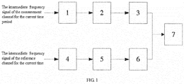
- Fig. 1 is a block diagram showing structure of the system for calculating the dynamically phase-shifted signal in real-time of the present invention, in which:
- a method for calculating a dynamically phase-shifted signal in real-time of the present invention comprising following steps:
- Fig. 1 shows a system for calculating a dynamically phase-shifted signal in real-time provided by the present invention, comprising:
- the method for calculating the dynamically phase-shifted signal in real-time of the present invention actually segments the intermediate frequency signals of the measurement channel and the reference channel into a plurality of reasonable small segments according to the time.
- the term of reasonable small segments means that time period of each of the reasonable small segments can meet the requirements for measuring time resolution, and the data in each of the reasonable small segments can be Fourier transformed within an accuracy range.
- a frequency of the intermediate frequency signal is 1 MHz
- a sampling rate is 12.5 MHz
- a time period is 20.48 microseconds.
- the person skilled in the art can accomplish the segmenting process.
- the signal of each of the small segments is recorded into an electronics chip by A/D conversion.
- the accurate frequency of the intermediate frequency signal can be found by Fourier transform. According to the found intermediate frequency signal value, filtration is performed within a set frequency band to reduce the noise. After filtration, the reference channel signal is compared with the measurement channel signal to obtain the phase difference between the intermediate frequency signals of the measurement channel and the reference channel for the current time period. Then obtaining and outputting the density and the current density data. Next, the phase for the next time period is calculated in the same way. The density and the current density data for the entire time are obtained by connecting all the data for each time period.
- the method for calculating the dynamically phase-shifted signal in real-time of the present invention can set a filtering step between step S03 and step S04:
- the system for calculating the dynamically phase-shifted signal in real-time can also dispose a measurement channel filter module 2 and/or reference channel filter module 5:
- the measurement channel fast Fourier transform module, the reference channel fast Fourier transform module, the measurement channel filter module, the reference channel filter module and/or the phase comparison module are programmed onto a FPGA chip.
- the measurement channel comprises three intermediate frequency signals
- the reference channel correspondingly comprises three intermediate frequency signals.
- the phase differences of the three pairs of the intermediate frequency signals in each time period are respectively and simultaneously calculated with steps S01 through S05.
- the diagnostic method for the nuclear fusion plasma on the basis of the aforementioned method for calculating the dynamically phase-shifted signal in real-time employs the method for calculating the dynamically phase-shifted signal in real-time to calculate the phase difference, and sets the following step after step S04:
- a step of storing, displaying and/or feeding back the calculated result can be further set as needed.
- the diagnostic system for a nuclear fusion plasma provided in the present invention further comprises an electron density/current density calculation module, wherein the electron density/current density calculation module calculates an electron density and a current density of the nuclear fusion plasma in real-time according to the phase difference calculated by the system for calculating the dynamically phase-shifted signal in real-time.
- a storage module for storing a calculation result, a display module for displaying the calculation result and/or a feedback system for feeding back the calculation result can be set as needed.
- the operation process of the diagnostic system for the nuclear fusion plasma using the system for calculating the dynamically phase-shifted signal in real-time of the present invention is as follows:
Landscapes
- Physics & Mathematics (AREA)
- Engineering & Computer Science (AREA)
- Plasma & Fusion (AREA)
- Spectroscopy & Molecular Physics (AREA)
- General Physics & Mathematics (AREA)
- Power Engineering (AREA)
- Measuring Phase Differences (AREA)
- Plasma Technology (AREA)
Applications Claiming Priority (1)
| Application Number | Priority Date | Filing Date | Title |
|---|---|---|---|
| PCT/CN2015/081243 WO2016197364A1 (fr) | 2015-06-11 | 2015-06-11 | Procédé et système de calcul en temps réel de signal de déphasage, procédé et système de diagnostic de plasma |
Publications (2)
| Publication Number | Publication Date |
|---|---|
| EP3297408A1 true EP3297408A1 (fr) | 2018-03-21 |
| EP3297408A4 EP3297408A4 (fr) | 2019-02-20 |
Family
ID=57502845
Family Applications (1)
| Application Number | Title | Priority Date | Filing Date |
|---|---|---|---|
| EP15894634.3A Ceased EP3297408A4 (fr) | 2015-06-11 | 2015-06-11 | Procédé et système de calcul en temps réel de signal de déphasage, procédé et système de diagnostic de plasma |
Country Status (3)
| Country | Link |
|---|---|
| EP (1) | EP3297408A4 (fr) |
| CN (1) | CN106461710B (fr) |
| WO (1) | WO2016197364A1 (fr) |
Families Citing this family (5)
| Publication number | Priority date | Publication date | Assignee | Title |
|---|---|---|---|---|
| CN112649678B (zh) * | 2020-12-24 | 2024-05-28 | 广州山锋测控技术有限公司 | 天馈线测量方法、装置、天馈线测量器件和测试仪 |
| CN112865888B (zh) * | 2021-01-11 | 2022-12-20 | 北京临近空间飞行器系统工程研究所 | 一种被动式在线电子密度辨识系统、方法及电子设备 |
| CN114828370B (zh) * | 2022-03-18 | 2024-04-19 | 合肥工业大学 | 一种用于等离子体密度测量的自适应相位差计算方法 |
| CN116298514A (zh) * | 2023-02-28 | 2023-06-23 | 北京华力创通科技股份有限公司 | 相位差测量方法、装置及系统 |
| CN119485884B (zh) * | 2024-11-18 | 2025-10-17 | 合肥综合性国家科学中心能源研究院(安徽省能源实验室) | 一种紧凑环等离子体速度计算方法及测量系统 |
Family Cites Families (6)
| Publication number | Priority date | Publication date | Assignee | Title |
|---|---|---|---|---|
| US4065665A (en) * | 1976-03-08 | 1977-12-27 | Deutsche Texaco Aktiengesellschaft | Method and apparatus for the determination of start time difference and overall phase shift between two signals |
| EP0702212A3 (fr) * | 1994-09-13 | 1996-08-14 | Fuji Electric Co Ltd | Dispositif de mesure des déphasages et débitmètre massique asscocié |
| JP4203008B2 (ja) * | 2002-04-30 | 2008-12-24 | 株式会社アドバンテスト | パターン位置検出装置、方法、プログラムおよび該プログラムを記録した記録媒体 |
| US8213885B2 (en) * | 2008-04-11 | 2012-07-03 | Nautel Limited | Impedance measurement in an active radio frequency transmitter |
| CA2722161C (fr) * | 2008-04-21 | 2016-05-24 | Anteverta-Mw B.V. | Agencement de traction de charge en boucle ouverte avec determination de signaux d'injection |
| CN104007435B (zh) * | 2014-04-24 | 2016-08-24 | 北京航空航天大学 | 一种基于中频相邻回波相位差的精确测速方法 |
-
2015
- 2015-06-11 EP EP15894634.3A patent/EP3297408A4/fr not_active Ceased
- 2015-06-11 CN CN201580028806.4A patent/CN106461710B/zh active Active
- 2015-06-11 WO PCT/CN2015/081243 patent/WO2016197364A1/fr not_active Ceased
Also Published As
| Publication number | Publication date |
|---|---|
| CN106461710A (zh) | 2017-02-22 |
| CN106461710B (zh) | 2019-09-17 |
| WO2016197364A1 (fr) | 2016-12-15 |
| EP3297408A4 (fr) | 2019-02-20 |
Similar Documents
| Publication | Publication Date | Title |
|---|---|---|
| Soltwisch | Current distribution measurement in a tokamak by FIR polarimetry | |
| EP3297408A1 (fr) | Procédé et système de calcul en temps réel de signal de déphasage, procédé et système de diagnostic de plasma | |
| Blair et al. | Phase sensitive detection as a means to recover signals buried in noise | |
| Jain et al. | An adaptive time-efficient technique for harmonic estimation of nonstationary signals | |
| CN109696415A (zh) | 一种基于快速傅里叶变换的气体吸收率在线测量方法 | |
| CN103941072A (zh) | 一种基于实数强跟踪滤波的电力信号突变参数测量方法 | |
| Ma et al. | Harmonic and interharmonic analysis of mixed dense frequency signals | |
| CN114924281B (zh) | 一种基于h13c14n气体池的调频连续波同时测距和测速方法及系统 | |
| CN114062312B (zh) | 一种tdlas气体检测中的锁相放大方法和系统 | |
| CN119310341A (zh) | 一种用于超同步间谐波的快速高精度频率测量方法 | |
| AU2021100076A4 (en) | Measuring frequency of microwave signal | |
| KR20170019831A (ko) | 부분방전 특성 분석 시스템 | |
| CN112067130B (zh) | 一种多频率分量的幅值提取方法及其系统 | |
| Cao et al. | Singular spectrum analysis for extracting low amplitude vibrations in femtosecond laser time-of-flight distance measurements | |
| CN109164275B (zh) | 一种伺服加速度计动态性能检测系统和方法 | |
| CN118981004B (zh) | 快速高精度镜像扫频干涉测量信号处理方法 | |
| CN104820145A (zh) | 用于对锁相放大器进行测试的测试仪及其测试方法 | |
| Bertocco et al. | Frequency tracking for efficient phasor measurement based on a CSTFM model | |
| CN117092662B (zh) | 一种风场探测的量子干涉激光雷达系统和方法 | |
| KR101997633B1 (ko) | Teo 및 desa를 이용한 자동 동기화 파라미터 측정 장치 | |
| CN114895547B (zh) | 一种波形自适应的大动态高精度时间测量仪器及测量方法 | |
| US20200059388A1 (en) | Device and method to transform discrete voltage pulses to a phase-sensitive continuous signal | |
| Hu et al. | Fractional rotational Doppler frequency shift for detecting spin acceleration | |
| CN111123286A (zh) | 一种基于自校准全光纤多普勒电缆长度测试方法及装置 | |
| Randall et al. | Application of power spectra to reactor system analysis |
Legal Events
| Date | Code | Title | Description |
|---|---|---|---|
| STAA | Information on the status of an ep patent application or granted ep patent |
Free format text: STATUS: THE INTERNATIONAL PUBLICATION HAS BEEN MADE |
|
| PUAI | Public reference made under article 153(3) epc to a published international application that has entered the european phase |
Free format text: ORIGINAL CODE: 0009012 |
|
| STAA | Information on the status of an ep patent application or granted ep patent |
Free format text: STATUS: REQUEST FOR EXAMINATION WAS MADE |
|
| 17P | Request for examination filed |
Effective date: 20171214 |
|
| AK | Designated contracting states |
Kind code of ref document: A1 Designated state(s): AL AT BE BG CH CY CZ DE DK EE ES FI FR GB GR HR HU IE IS IT LI LT LU LV MC MK MT NL NO PL PT RO RS SE SI SK SM TR |
|
| AX | Request for extension of the european patent |
Extension state: BA ME |
|
| DAV | Request for validation of the european patent (deleted) | ||
| DAX | Request for extension of the european patent (deleted) | ||
| A4 | Supplementary search report drawn up and despatched |
Effective date: 20190117 |
|
| RIC1 | Information provided on ipc code assigned before grant |
Ipc: H03L 7/085 20060101ALI20190111BHEP Ipc: H03D 13/00 20060101ALI20190111BHEP Ipc: H05H 1/00 20060101AFI20190111BHEP Ipc: G01R 25/00 20060101ALI20190111BHEP |
|
| STAA | Information on the status of an ep patent application or granted ep patent |
Free format text: STATUS: EXAMINATION IS IN PROGRESS |
|
| 17Q | First examination report despatched |
Effective date: 20210315 |
|
| REG | Reference to a national code |
Ref country code: DE Ref legal event code: R003 |
|
| STAA | Information on the status of an ep patent application or granted ep patent |
Free format text: STATUS: THE APPLICATION HAS BEEN REFUSED |
|
| 18R | Application refused |
Effective date: 20230713 |