EP3297724B1 - Elektrodenanordnung für wundbehandung - Google Patents
Elektrodenanordnung für wundbehandung Download PDFInfo
- Publication number
- EP3297724B1 EP3297724B1 EP16745197.0A EP16745197A EP3297724B1 EP 3297724 B1 EP3297724 B1 EP 3297724B1 EP 16745197 A EP16745197 A EP 16745197A EP 3297724 B1 EP3297724 B1 EP 3297724B1
- Authority
- EP
- European Patent Office
- Prior art keywords
- electrode
- electrode arrangement
- plasma
- planar
- dielectric
- Prior art date
- Legal status (The legal status is an assumption and is not a legal conclusion. Google has not performed a legal analysis and makes no representation as to the accuracy of the status listed.)
- Active
Links
Images


Classifications
-
- A—HUMAN NECESSITIES
- A61—MEDICAL OR VETERINARY SCIENCE; HYGIENE
- A61N—ELECTROTHERAPY; MAGNETOTHERAPY; RADIATION THERAPY; ULTRASOUND THERAPY
- A61N1/00—Electrotherapy; Circuits therefor
- A61N1/02—Details
- A61N1/04—Electrodes
- A61N1/0404—Electrodes for external use
- A61N1/0408—Use-related aspects
- A61N1/0464—Specially adapted for promoting tissue growth
-
- A—HUMAN NECESSITIES
- A61—MEDICAL OR VETERINARY SCIENCE; HYGIENE
- A61B—DIAGNOSIS; SURGERY; IDENTIFICATION
- A61B18/00—Surgical instruments, devices or methods for transferring non-mechanical forms of energy to or from the body
- A61B18/04—Surgical instruments, devices or methods for transferring non-mechanical forms of energy to or from the body by heating
- A61B18/042—Surgical instruments, devices or methods for transferring non-mechanical forms of energy to or from the body by heating using additional gas becoming plasma
-
- A—HUMAN NECESSITIES
- A61—MEDICAL OR VETERINARY SCIENCE; HYGIENE
- A61N—ELECTROTHERAPY; MAGNETOTHERAPY; RADIATION THERAPY; ULTRASOUND THERAPY
- A61N1/00—Electrotherapy; Circuits therefor
- A61N1/02—Details
- A61N1/04—Electrodes
- A61N1/0404—Electrodes for external use
- A61N1/0408—Use-related aspects
- A61N1/0468—Specially adapted for promoting wound healing
-
- A—HUMAN NECESSITIES
- A61—MEDICAL OR VETERINARY SCIENCE; HYGIENE
- A61N—ELECTROTHERAPY; MAGNETOTHERAPY; RADIATION THERAPY; ULTRASOUND THERAPY
- A61N1/00—Electrotherapy; Circuits therefor
- A61N1/02—Details
- A61N1/04—Electrodes
- A61N1/0404—Electrodes for external use
- A61N1/0472—Structure-related aspects
-
- A—HUMAN NECESSITIES
- A61—MEDICAL OR VETERINARY SCIENCE; HYGIENE
- A61N—ELECTROTHERAPY; MAGNETOTHERAPY; RADIATION THERAPY; ULTRASOUND THERAPY
- A61N1/00—Electrotherapy; Circuits therefor
- A61N1/18—Applying electric currents by contact electrodes
- A61N1/32—Applying electric currents by contact electrodes alternating or intermittent currents
- A61N1/326—Applying electric currents by contact electrodes alternating or intermittent currents for promoting growth of cells, e.g. bone cells
-
- A—HUMAN NECESSITIES
- A61—MEDICAL OR VETERINARY SCIENCE; HYGIENE
- A61N—ELECTROTHERAPY; MAGNETOTHERAPY; RADIATION THERAPY; ULTRASOUND THERAPY
- A61N1/00—Electrotherapy; Circuits therefor
- A61N1/44—Applying ionised fluids
-
- H—ELECTRICITY
- H05—ELECTRIC TECHNIQUES NOT OTHERWISE PROVIDED FOR
- H05H—PLASMA TECHNIQUE; PRODUCTION OF ACCELERATED ELECTRICALLY-CHARGED PARTICLES OR OF NEUTRONS; PRODUCTION OR ACCELERATION OF NEUTRAL MOLECULAR OR ATOMIC BEAMS
- H05H1/00—Generating plasma; Handling plasma
- H05H1/24—Generating plasma
- H05H1/2406—Generating plasma using dielectric barrier discharges, i.e. with a dielectric interposed between the electrodes
-
- H—ELECTRICITY
- H05—ELECTRIC TECHNIQUES NOT OTHERWISE PROVIDED FOR
- H05H—PLASMA TECHNIQUE; PRODUCTION OF ACCELERATED ELECTRICALLY-CHARGED PARTICLES OR OF NEUTRONS; PRODUCTION OR ACCELERATION OF NEUTRAL MOLECULAR OR ATOMIC BEAMS
- H05H2245/00—Applications of plasma devices
- H05H2245/30—Medical applications
- H05H2245/36—Sterilisation of objects, liquids, volumes or surfaces
Definitions
- This invention relates to an electrode arrangement for wound treatment of an irregularly three-dimensionally shaped surface of an electrically conducting body, which surface is used as a counter electrode.
- the invention relates to devices that can be applied e.g. for preventing diabetic foot complications.
- Cold plasmas have considerable potential for skin conditioning, disinfection of skin and wound healing.
- available plasma sources lack the possibility to treat larger areas, to control plasma properties and/or the possibility to adapt the shape of the plasma to the shape of the object to be treated (e.g. a foot).
- This invention focuses on: a cold plasma device, which can treat a larger area.
- the flexible plasma device is a platform technology with a number of interesting applications and market possibilities to improve skin conditions, prevent ulcerations and accelerate healing of the diabetic foot.
- the plasma can easily be delivered to the skin of a patient, e.g. in the form of a plasma plaster.
- the skin will be temporary exposed to the plasma to disinfect the skin and to improve cell proliferation and microcirculation of the blood.
- one-minute plasma treatment will reduce the bacterial load on the foot with up to a factor of one million, without negatively affecting the skin.
- Such a treatment should be continued on a once/twice per day basis until the threat of infection has been overcome.
- embodiments of the invention pertain to: an electrode arrangement according to the features of claim 1.
- the present invention rather than having a flexible electrode with projections as known from US9005188 , provides a compartmented structure such that upon contact with the skin a number of closed compartments is realized where the plasma is generated.
- the advantage of having closed compartments, rather than the open air guiding areas, is that the main chemical components generated by the plasma (e.g. ozone) is/are fixed in a closed environment. This prevents release of ozone to the environment and increases the effectiveness of the plasma generated.
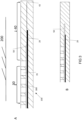
- FIG 1 shows a schematic perspective view of a prototype of the cold plasma device.
- Figure 2 shows the device of Figure 1 in schematic cross sectional view.
- Figure 3 shows an edge detail of the cross sectional view in Figure 2 .
- the plasma device 100 provides a dielectric barrier discharge (DBD) technique for plasma plaster development.
- DBD dielectric barrier discharge
- a DBD type of plasma source has a planar electrode 20 that is covered with a dielectric foil or film 50.
- a gas (or air) gap is present in a compartment 30 formed between an object to be treated (e.g. foot) being functioning as electrode 200 and dielectric 50 with a dielectric constant e.g. larger than 2.
- object to be treated 200 is shown apart from device 100, but in use, edge 40 firmly contacts object 200.
- the electrode 20 is powered by pulsed or AC high-voltage. Due to the dielectric 50, the electric field is mainly present in the air gap 35 formed by protrusions 300 in the structured surface 30.
- the protrusions 300 ensure a minimum distance of the electrode 20 to the object 200 e.g. larger than 1mm. If the electric field is high enough (>30 kV/cm) and if the thickness of the air gap is rather constant, homogeneous cold plasma is created in the air gap to the object to be treated (e.g. the skin of a foot). Dielectric and protrusions have a high dielectric strength, e.g. > 180 kV/mm.
- a DBD cold plasma device can treat large areas; the dimensions of the DBD can be chosen over wide margins. Instead of allowing for airflow between the cold plasma device and the skin, discrete compartments 30 are formed that will contain some air, but these need not be connected to each other, they are isolated from each other, and also isolated to the surroundings by a closed edge.
- the advantage is that the reactive gases that we will generate during operation of the cold plasma, gases like ozone cannot escape. This has the advantage that the device is more efficient: all reactive specimens are available to kill pathogens, and that the release of any toxic gases like ozone will be minimized.
- the compartments can have any shape as long as they are separated from each other, and also they may vary in size and shape, even within one device. Also, each device will have a closed edge in order to prevent release of any gases to the surroundings.
- the device can have any shape, round square, irregularly shaped, and have an edge (typically 1 cm) as described earlier.
- an electrode arrangement 100 is shown for a dielectric barrier discharge plasma treatment of an irregularly three-dimensionally shaped surface of an electrically conducting body.
- the body is typically a human body part, such as a foot, heel, toe, finger or any other diseased skin part, which surface is used as a counter electrode.
- the arrangement has a first planar electrode 20 to be coupled to a high voltage source a dielectric 50 (see Figure 3 ) which is formed by a flexible material in such a way that the dielectric 50 shields the first planar electrode from the surface to be treated; a spacer structure 30 defining a structured surface on a side of said arrangement 100 facing a surface 200 to be treated, such that the structured surface forms one or more spaced compartments 30 that are isolated by an edge 40 from the surroundings in order to prevent airflow between the surroundings and the compartments 30.
- the device 100 has a an electrode 20 that is fitted to the object to be treated 200 and brought in contact with the dielectric, in order to provide a substantially conformal compartment that follows the contours of the 3D shaped body for providing a homogenous microdischarged plasma.
- an electrode 20 fitted to the object to be treated the occurrence of saddle points or sharp folds prevents undesired local field strengths. It may be desirable to shape the electrode centrally to a concave or convex form of the surface to be treated, to optimize the local stretch of the electrode 20, so that the device optimally adapts to the object 200.
- the first planar electrode is a mesh.
- a mesh is suitably adaptable to the 3D shape, and will not rupture, crease or fold.
- the mesh may be contacted by a twisted pair lead 23, that connects to a high voltage clamp 25, and a ground electrode clamp 26 that connects to the second electrode respectively, said lead integrated in lead portion 45 integral to the edge 40. It was found that a mesh is stretchably deformable around three dimensional of an object to be treated, such as a heel, finger or toe, while still being able to provide a suitable homogenous plasma. It will be understood that 'stretchable' is to be understood in a conventional context known to the skilled person, i.e.
- the structured surface comprises an edge portion 40 wherein the first planar electrode 20 extends into the edge portion 40.
- Figure 4 shows a variety of electrode structures 20, 220 and 222. It is shown that the mesh may be provided by woven conductive threads, typically metallic, with a weave that allows in plane deformations. In contrast to electrode 20, that has a weave with straight non-connected parallel wires, electrode structure 220 by forming the first electrode from a continuous conductive wire. In this embodiment, a weave from a single wire, or from wires with a non-intersecting meandering pattern, further prevents breakthrough problems. In another electrode weave 222, the wire is provided with a in intersecting meandering weave pattern.
- the plasma can be powered by repetitive, short high-voltage pulses (ns- ⁇ s duration, up to a few 100 kHz repetition rate).
- a driver circuit 600 is provided for driving the planar electrode, wherein the driver circuit drives the planar electrode in a pulsed voltage in a range of 3-8kV, in a range of 0.5-100kHz, and a pulse duration in a range of 1-150 micro second.
- This allows for a pulse rate that substantially provides a micro discharge wherein electrical current through the object to be treated (skin, human body) will only flow during the time that the plasma is on (which is typically equal to the HV pulse duration).
- the plasma In between the pulses, the plasma is not active, and no current flows through the skin.
- the plasma would be powered by AC voltage, current flow happens during the entire AC cycle, while the plasma is active only during a small part of the AC cycle.
- the pulsed operation of the plasma enables perfect control over the power of the plasma by means of the pulse repetition rate. In this way, the plasma power can be controlled and adjusted without affecting the plasma properties.
- controlling the power is only possible by means of the voltage magnitude, and thus affects the plasma properties.
- Pulse sequences can be optimized towards a specific application.
- the grounded electrode 26 as shown in Figure 1 will enhance safety (prevents plasma generation and/or high-voltage to be present outside of the device), and also reduces electromagnetic emission of the device. This allows the device to be used without problems in any (electrical) environment.
- Figure 5 shows that a second planar electrode 261 completely covers said stretchable isolating cover layer.
- the second planar electrode 261 may be connected to the ground electrode 26.
- the second planar electrode 261 is furthermore connected to conductive ring electrode 260 that is provided in the edge portion.
- This conductive ring electrode may be formed with a conductive sticker edge that is attachable to the human skin.
- 3D convex forms such as a heel portion
- Figure 6 provides a schematic cross sectional view of the embodiment of Figure 5 .
- a (rather) constant width of the gas gap (up to a few mm) is required.
- a structured interface is provided (see figure 2 ) that provides a constant distance between the dielectric barrier and the object to be treated. This is an essential condition for the proper functioning of a DBD device.
- This can be even better accomplished by a dielectric 50 that is formed by a stack 500 of dielectric layers 50.
- a stack 500 of one or more thin foil dielectrics has a possibility to prevent any pinholes that would form an unshielded channel between the electrode and the grounded treatment surface, without any dielectric. This improves the homogeneity of the electric field and corresponding plasma forming.
- Figure 7 shows a further embodiment wherein the conductive ring 260 has an extending lip designed to slightly press into a skin portion for further ensuring grounding of the conductive ring 260.
- the device is provided with an interface 36 layer (See Figure 8 ) between the plasma electrode stack (including dielectric) 500 and the object to be treated so that the gas environment in which the plasma is generated can be tailored (and thus the plasma properties can be tailored) and that provides a constant distance to the object to be treated.
- an interface 36 layer See Figure 8
- the interface 36 may have a controlled composition of gases that in combination with HV driver settings will generate a tailor-made mixture of reactive gases. Also, this layer can act as absorber for e.g. unwanted O3.
- the function of 36 is threefold:
- the properties of the cold plasma depend on the type of gas that is present in the gas gap.
- the interface 36 between the plasma electrodes and the object to be treated allows buffering or storage of gas and the (triggered) slow release of gas during the time that the plasma is running. So the gas environment in which the plasma is generated can be tailored, without the need for gas bottles and associated tubing and flow control. Thus also the plasma properties can be tailored.
- the device can for example be integrated in a mold or plaster that fits to the part of the body that must be treated.
- Such assemblies can be made patient specific, and can be used during the entire treatment period of the patient.
- the interface layer 36 may be constructed as an integral part of a patient specific plasma device, which simultaneously is designed to create an air gap.
- the interface layer can also be a separate device that will be applied temporarily, e.g. in the form of a disposable. Before use, the disposable can be kept in a closed or sealed package or bag. It can be thrown away after use. Storing the disposable into a sealed package allows it to keep it sterile. So there is no need to clean the interface before use.
- a sealed package can also be filled with a preferred gas, thus supporting the buffering of gas in the interface.
- the interface layer 36 of the plasma device 100 Several options are available to construct the interface layer 36 of the plasma device 100.
- One option is to use a (thin) layer of silica aerogel material 36.
- Silicon aerogels find application in drug delivery and have good bio-compatibility. Aerogels have the required electrical properties (they also find application as high-voltage insulators), such as a dielectric constant between 2-4 and a high dielectric strength. Due to the high porosity (>85%) and homogeneous feature of aerogels, the generation of plasma is not hampered by such a layer. The high porosity and large surface area (>400 m2/gram) allows buffering and the slow release of gas. This has been demonstrated for hydrogen fuel storage and for drug delivery applications (where the drugs are in solution with CO2 gas).
- gases such as nitrogen, helium, argon and air can be stored without any problem.
- the slow release of gas will start as soon as the device is taken out of its sealed package.
- the gas release rate can be controlled by the aerogel density and surface area. Gas release may also be triggered (e.g. by the intense electric field or the UV emission of the plasma). Accordingly the gas release rate can be affected by the plasma intensity.
- Another option to construct the interface is to use a (thin) layer or a patch of polymer material.
- the polymer material contains gas reservoirs that are loaded with the preferred gas.
- Plasma is generated into these gas reservoirs 300.
- interface layer 36 provides a protrusion structure for forming these reservoirs and ensuring a minimal distance to the skin.
- the plasma products must be released to the object to be treated (skin). This can be done by for instance permeation and/or diffusion through the polymer membrane. Another way is to rupture the polymeric membrane by means of the plasma (e.g. by the UV or by the intense electric field).
- a third option is to use polymeric gas dispenser materials.
- An example is AIBN that can be used to release N2.
- Another example is silver oxide that can be used to release O2.
- Such materials are used for instance as oxygen generator in airplanes or for very fast gas release in airbags.
- gas release is triggered thermally.
- gas release is triggered by the plasma (UV).
- more complex materials such as zeolites, barium peroxide and azides can be used for gas dispenser applications. However, these materials have poor biocompatibility.
- Such an interface layer 36 can be provided by both a so called “dielectric barrier discharge” (DBD), or a surface dielectric barrier discharge (SDBD).
- DBD dielectric barrier discharge
- SDBD surface dielectric barrier discharge
- flexible materials e.g. plastic or synthetic rubber foils/films, metallic foils, conductive fabrics
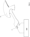
- a flexible construction can be made, that allows to fit the shape of the plasma to the shape of the object to be treated see e.g. Figure 9 , giving an impression how this device can be applied for diabetic foot treatment.
- the electrode form 20 is fitted to the object to be treated by closely following the contour of the heel 200.
- Such electrode form can be integrated into a silicon rubber mould 30 or into a plaster cast, which fits around a heel or toe.
- the electrode may e.g.
- the mesh electrode configuration 20 can be adapted to have a pair of high voltage wire electrodes 20 provided alternating parallel with grounded wiring 25, to create a surface dielectric barrier discharge between adjacent wire electrodes 20, 25.
- remote monitoring e.g. via Internet could be incorporated into the device.
Landscapes
- Health & Medical Sciences (AREA)
- Engineering & Computer Science (AREA)
- Life Sciences & Earth Sciences (AREA)
- Biomedical Technology (AREA)
- Nuclear Medicine, Radiotherapy & Molecular Imaging (AREA)
- Animal Behavior & Ethology (AREA)
- General Health & Medical Sciences (AREA)
- Public Health (AREA)
- Veterinary Medicine (AREA)
- Radiology & Medical Imaging (AREA)
- Physics & Mathematics (AREA)
- Plasma & Fusion (AREA)
- Surgery (AREA)
- Cell Biology (AREA)
- Orthopedic Medicine & Surgery (AREA)
- Spectroscopy & Molecular Physics (AREA)
- Otolaryngology (AREA)
- Heart & Thoracic Surgery (AREA)
- Medical Informatics (AREA)
- Molecular Biology (AREA)
- Plasma Technology (AREA)
- Physical Or Chemical Processes And Apparatus (AREA)
Claims (15)
- Elektrodenanordnung (100) zur Wundbehandlung einer unregelmäßig dreidimensional geformten Oberfläche eines elektrisch leitenden Körpers (200), wobei die Oberfläche als eine Gegenelektrode genutzt wird, umfassend- eine erste planare Elektrode (20), die mit einer Hochspannungsquelle gekoppelt werden soll, wobei die planare Elektrode (20) mit einer dielektrischen Folie oder Film (50) bedeckt ist, die von einem flexiblen Material derart gebildet werden, dass das Dielektrikum die erste planare Elektrode (20) von der zu behandelnden Oberfläche abschirmt;- ein Abstandhalter (30), der eine strukturierte Oberfläche auf einer Seite der Anordnung definiert, die einer zu behandelnden Oberfläche zugewandt ist, so dass die strukturierte Oberfläche eine oder mehrere beabstandete Abteile (30) bildet, die durch Vorsprünge (300) voneinander isoliert sind, die einen Mindestabstand der Elektrode (20) zum Objekt gewährleisten; und die von der Umgebung der Abteile durch eine Kante (40) isoliert sind, um einen Luftstrom zwischen der Umgebung und den Abteilen (30) zu verhindern,- wobei die erste planare Elektrode (20) an dem zu behandelnden Objekt (200) angebracht und in Kontakt mit dem Dielektrikum gebracht wird, und- eine isolierende Deckschicht, die die erste planare Elektrode (20) bedeckt.
- Elektrodenanordnung nach Anspruch 1, wobei das Dielektrikum durch einen Stapel (500) dielektrischer Schichten gebildet ist.
- Elektrodenanordnung nach einem der vorhergehenden Ansprüche, wobei die strukturierte Oberfläche einen Kantenabschnitt (40) umfasst, wobei sich die erste planare Elektrode (20) in den Kantenabschnitt (40) erstreckt.
- Elektrodenanordnung nach Anspruch 3, wobei der Kantenabschnitt (40) nicht dehnbar ist.
- Elektrodenanordnung nach einem der vorhergehenden Ansprüche, wobei die erste planare Elektrode (20) ein dehnbares Netz ist.
- Elektrodenanordnung nach einem der vorhergehenden Ansprüche, wobei die erste planare Elektrode (20) aus einem kontinuierlich leitenden Draht gebildet ist.
- Elektrodenanordnung nach einem der vorhergehenden Ansprüche, wobei die erste planare Elektrode (20) aus einem leitenden Draht gebildet ist, der mit einem Dielektrikum beschichtet ist.
- Elektrodenanordnung nach einem der vorhergehenden Ansprüche, wobei die erste planare Elektrode (20) mit einer verdrillten Paarleitung (23) kontaktiert ist, die mit einer Hochspannungsklemme verbunden ist, bzw. einer Erdungselektrodenklemme, die mit der zweiten Elektrode (26) verbunden ist, wobei die Leitung in einen in die Kante integrierten Leitungsabschnitt integriert ist.
- Elektrodenanordnung nach einem der vorhergehenden Ansprüche, wobei die Elektrodenanordnung im Wesentlichen durchsichtig ist, so dass ein darunterliegender Körper (200) und das erzeugte Plasma sichtgeprüft werden können.
- Elektrodenanordnung nach einem der vorhergehenden Ansprüche, wobei die isolierende Deckschicht und der Abstandhalter (30) aus einer einzigen durchsichtigen biegsamen Vorform bereitgestellt sind.
- Elektrodenanordnung nach einem der vorhergehenden Ansprüche, wobei die planare Elektrode mit einem Kontakt mit Gleitkontakten eines PCB Konnektors verbunden ist.
- Elektrodenanordnung nach einem der vorhergehenden Ansprüche, ferner umfassend eine Treiberschaltung zum Antreiben der mit der Hochspannungsquelle gekoppelten planaren Elektrode, wobei die Treiberschaltung die planare Elektrode in einer gepulsten Spannung in einem Bereich von 3-8 kV, einer Wiederholungsrate in einem Bereich von 0,5-50 kHz und einer Pulsdauer in einem Bereich von 0,1-100 Mikrosekunden antreibt
- Elektrodenanordnung nach Anspruch 12, wobei die Treiberschaltung eine planare Elektroden-Identifikationsschaltung aufweist.
- Elektrodenanordnung nach einem der vorhergehenden Ansprüche, wobei in der Elektrodenanordnung eine weitere Gassteuerstruktur vorgesehen ist, die zur Erzeugung eines Plasmavorläufergases angeordnet ist.
- Elektrodenanordnung nach Anspruch 14, wobei die Gassteuerstruktur einen Gasabfluss oder ein Gasabsorptionsmittel umfasst.
Applications Claiming Priority (2)
| Application Number | Priority Date | Filing Date | Title |
|---|---|---|---|
| US201562163578P | 2015-05-19 | 2015-05-19 | |
| PCT/NL2016/050359 WO2016186501A2 (en) | 2015-05-19 | 2016-05-19 | Non-thermal plasma device |
Publications (3)
| Publication Number | Publication Date |
|---|---|
| EP3297724A2 EP3297724A2 (de) | 2018-03-28 |
| EP3297724C0 EP3297724C0 (de) | 2023-08-16 |
| EP3297724B1 true EP3297724B1 (de) | 2023-08-16 |
Family
ID=56555689
Family Applications (1)
| Application Number | Title | Priority Date | Filing Date |
|---|---|---|---|
| EP16745197.0A Active EP3297724B1 (de) | 2015-05-19 | 2016-05-19 | Elektrodenanordnung für wundbehandung |
Country Status (3)
| Country | Link |
|---|---|
| US (1) | US20180140824A1 (de) |
| EP (1) | EP3297724B1 (de) |
| WO (1) | WO2016186501A2 (de) |
Families Citing this family (16)
| Publication number | Priority date | Publication date | Assignee | Title |
|---|---|---|---|---|
| US11042027B2 (en) * | 2016-03-07 | 2021-06-22 | King Abdullah University Of Science And Technology | Non thermal plasma surface cleaner and method of use |
| DE102017100161B4 (de) * | 2017-01-05 | 2022-08-04 | Cinogy Gmbh | Flächiges flexibles Auflagestück für eine dielektrisch behinderte Plasmabehandlung |
| DE102017100192A1 (de) * | 2017-01-06 | 2018-07-12 | Cinogy Gmbh | Permanente Wundauflage mit Plasmaelektrode |
| DE102017116305A1 (de) | 2017-07-19 | 2019-01-24 | Cinogy Gmbh | Plasma-Behandlungsgerät |
| KR101922507B1 (ko) * | 2017-11-29 | 2018-11-28 | 주식회사 서린메디케어 | 프락셔널 플라즈마를 이용한 피부 치료장치 |
| NL2020126B1 (en) * | 2017-12-19 | 2019-06-26 | Plasmacure B V | EMC control for pulsed high voltage source of a plasma device for medical treatment |
| CN112512449B (zh) * | 2018-07-31 | 2024-08-06 | 莱雅公司 | 冷等离子体生成装置、系统以及方法 |
| ES2974157T3 (es) | 2018-07-31 | 2024-06-26 | Oreal | Generación de plasma frío lejos de la piel, y sistemas asociados |
| NL2021675B1 (en) * | 2018-09-20 | 2020-05-07 | Plasmacure B V | Driver circuit for a dielectric barrier discharge plasma treatment |
| KR102031713B1 (ko) * | 2019-01-29 | 2019-10-14 | (주)에스제이글로벌 | 창상치료용 플라즈마 전극 패드 및 플라즈마 치료 장치 |
| DE102019006536B3 (de) * | 2019-09-16 | 2020-12-31 | Blv Licht- Und Vakuumtechnik Gmbh | Vorrichtung und Verfahren zur Haut- und insbesondere Wundbehandlung unter Verwendung von Plasma |
| DE102020100828B4 (de) | 2020-01-15 | 2023-03-09 | Tdk Electronics Ag | Vorrichtung zur Erzeugung einer dielektrischen Barriereentladung und Verfahren zur Behandlung eines zu aktivierenden Objekts |
| CN111988902B (zh) * | 2020-08-14 | 2022-08-05 | 清华大学 | 一种可弯曲的气囊式等离子体发生器 |
| EP4259017A1 (de) * | 2020-12-14 | 2023-10-18 | Covidien LP | Energieerzeuger mit multifunktionalem energieaufnahmefach |
| NL2027148B1 (en) * | 2020-12-17 | 2022-07-11 | Plasmacure B V | Treatment pad for a dielectric barrier discharge plasma treatment |
| CN113556855B (zh) * | 2021-07-22 | 2022-06-10 | 重庆大学 | 一种三电极双源激励等离子体发生装置 |
Family Cites Families (8)
| Publication number | Priority date | Publication date | Assignee | Title |
|---|---|---|---|---|
| US6149620A (en) * | 1995-11-22 | 2000-11-21 | Arthrocare Corporation | System and methods for electrosurgical tissue treatment in the presence of electrically conductive fluid |
| US20030168009A1 (en) * | 2002-03-08 | 2003-09-11 | Denes Ferencz S. | Plasma processing within low-dimension cavities |
| DE102007030915A1 (de) * | 2007-07-03 | 2009-01-22 | Cinogy Gmbh | Vorrichtung zur Behandlung von Oberflächen mit einem mittels einer Elektrode über ein Feststoff-Dielektrikum durch eine dielektrische behinderte Gasentladung erzeugten Plasma |
| DE102009060627B4 (de) | 2009-12-24 | 2014-06-05 | Cinogy Gmbh | Elektrodenanordnung für eine dielektrisch behinderte Plasmabehandlung |
| GB201021032D0 (en) * | 2010-12-10 | 2011-01-26 | Creo Medical Ltd | Electrosurgical apparatus |
| EP2670477B1 (de) | 2011-02-01 | 2015-11-25 | Moe Medical Devices LLC | Plasmaunterstützte hautbehandlung |
| EP2760536A4 (de) * | 2011-09-17 | 2015-05-06 | Moe Medical Devices Llc | Systeme, verfahren und maschinenlesbare programme für elektrofeld- und/oder plasmaunterstützte behandlung von nagelpilz |
| DE102012207750A1 (de) * | 2012-05-09 | 2013-11-28 | Leibniz-Institut für Plasmaforschung und Technologie e.V. | Vorrichtung zur plasmabehandlung von menschlichen, tierischen oder pflanzlichen oberflächen, insbesondere von haut oder schleimhautarealen |
-
2016
- 2016-05-19 WO PCT/NL2016/050359 patent/WO2016186501A2/en not_active Ceased
- 2016-05-19 EP EP16745197.0A patent/EP3297724B1/de active Active
- 2016-05-19 US US15/574,713 patent/US20180140824A1/en active Pending
Also Published As
| Publication number | Publication date |
|---|---|
| US20180140824A1 (en) | 2018-05-24 |
| WO2016186501A3 (en) | 2017-03-23 |
| EP3297724C0 (de) | 2023-08-16 |
| EP3297724A2 (de) | 2018-03-28 |
| WO2016186501A2 (en) | 2016-11-24 |
Similar Documents
| Publication | Publication Date | Title |
|---|---|---|
| EP3297724B1 (de) | Elektrodenanordnung für wundbehandung | |
| EP3541311B1 (de) | Non-therma-plasmavorrichtung mit steuerung der elektromagnetischen verträglichkeit | |
| US11006995B2 (en) | Device for the planar treatment of areas of human or animal skin or mucous membrane surfaces by means of a cold atmospheric pressure plasma | |
| JP5319709B2 (ja) | 電気穿孔された細胞を選択的に治療するプラズマ機器 | |
| US11724078B2 (en) | Methods and systems for trans-tissue substance delivery using plasmaporation | |
| US11622439B2 (en) | Apparatus and methods for treatment using non-thermal plasma | |
| US10307606B2 (en) | Device for generating plasma, system for generating plasma and method for generating plasma | |
| JP5281715B2 (ja) | 内部に埋め込まれた電極を有する接続ハイドロゲルビードを組み込む外科用創傷被覆 | |
| US20160271411A1 (en) | Cold plasma pressure treatment system | |
| BR112017007257B1 (pt) | Dispositivo para produzir um plasma frio em pressão atmosférica para o tratamento de superfícies humanas e/ou animais, cabo para conectar com um dispositivo, unidade geradora para fornecer uma alta tensão para produzir umplasma frio em pressão atmosférica com um dispositivo, e sistema | |
| US20170050039A1 (en) | Plasma hydrogel therapy | |
| US20230285630A1 (en) | Plasma hydrogel therapy | |
| CN109644547A (zh) | 伤口敷料 | |
| JP7447290B2 (ja) | プラズマ活性液を生成する医療機器および方法 | |
| KR101286272B1 (ko) | 피복재 및 전기자극기가 구비된 의료기기 | |
| CN110420387B (zh) | 基于大气压柔性低温等离子体的足部干式灭菌装置 | |
| KR20170004059A (ko) | 피부 처리용 플라즈마 스틱 | |
| CN116114387A (zh) | 用于利用非热等离子体灭活微生物的装置和方法 | |
| CN113730232A (zh) | 基于等离子体技术的3d一体式可充电穴位按摩装置 | |
| EP3490668B1 (de) | Vorrichtung zur therapeutischen behandlung von gewebeverletzungen | |
| CN120168736A (zh) | 创面修复系统 | |
| HK40094678A (zh) | 用於利用非热等离子体灭活微生物的装置和方法 | |
| Class et al. | Patent application title: PLASMA HYDROGEL THERAPY | |
| MXPA03009743A (es) | Metodo y sistema para la administracion electrocinetica de una substancia. |
Legal Events
| Date | Code | Title | Description |
|---|---|---|---|
| STAA | Information on the status of an ep patent application or granted ep patent |
Free format text: STATUS: THE INTERNATIONAL PUBLICATION HAS BEEN MADE |
|
| PUAI | Public reference made under article 153(3) epc to a published international application that has entered the european phase |
Free format text: ORIGINAL CODE: 0009012 |
|
| STAA | Information on the status of an ep patent application or granted ep patent |
Free format text: STATUS: REQUEST FOR EXAMINATION WAS MADE |
|
| 17P | Request for examination filed |
Effective date: 20171204 |
|
| AK | Designated contracting states |
Kind code of ref document: A2 Designated state(s): AL AT BE BG CH CY CZ DE DK EE ES FI FR GB GR HR HU IE IS IT LI LT LU LV MC MK MT NL NO PL PT RO RS SE SI SK SM TR |
|
| AX | Request for extension of the european patent |
Extension state: BA ME |
|
| DAV | Request for validation of the european patent (deleted) | ||
| DAX | Request for extension of the european patent (deleted) | ||
| RAP1 | Party data changed (applicant data changed or rights of an application transferred) |
Owner name: PLASMACURE B.V. |
|
| RIN1 | Information on inventor provided before grant (corrected) |
Inventor name: ZEPER, WOUTER BASTIAAN Inventor name: PEMEN, AUGUST JOHANNES MARIE |
|
| STAA | Information on the status of an ep patent application or granted ep patent |
Free format text: STATUS: EXAMINATION IS IN PROGRESS |
|
| 17Q | First examination report despatched |
Effective date: 20220222 |
|
| GRAP | Despatch of communication of intention to grant a patent |
Free format text: ORIGINAL CODE: EPIDOSNIGR1 |
|
| STAA | Information on the status of an ep patent application or granted ep patent |
Free format text: STATUS: GRANT OF PATENT IS INTENDED |
|
| INTG | Intention to grant announced |
Effective date: 20230301 |
|
| GRAS | Grant fee paid |
Free format text: ORIGINAL CODE: EPIDOSNIGR3 |
|
| GRAA | (expected) grant |
Free format text: ORIGINAL CODE: 0009210 |
|
| STAA | Information on the status of an ep patent application or granted ep patent |
Free format text: STATUS: THE PATENT HAS BEEN GRANTED |
|
| AK | Designated contracting states |
Kind code of ref document: B1 Designated state(s): AL AT BE BG CH CY CZ DE DK EE ES FI FR GB GR HR HU IE IS IT LI LT LU LV MC MK MT NL NO PL PT RO RS SE SI SK SM TR |
|
| REG | Reference to a national code |
Ref country code: GB Ref legal event code: FG4D |
|
| REG | Reference to a national code |
Ref country code: CH Ref legal event code: EP Ref country code: DE Ref legal event code: R096 Ref document number: 602016081963 Country of ref document: DE |
|
| REG | Reference to a national code |
Ref country code: IE Ref legal event code: FG4D |
|
| U01 | Request for unitary effect filed |
Effective date: 20230914 |
|
| U07 | Unitary effect registered |
Designated state(s): AT BE BG DE DK EE FI FR IT LT LU LV MT NL PT SE SI Effective date: 20230921 |
|
| PG25 | Lapsed in a contracting state [announced via postgrant information from national office to epo] |
Ref country code: GR Free format text: LAPSE BECAUSE OF FAILURE TO SUBMIT A TRANSLATION OF THE DESCRIPTION OR TO PAY THE FEE WITHIN THE PRESCRIBED TIME-LIMIT Effective date: 20231117 |
|
| PG25 | Lapsed in a contracting state [announced via postgrant information from national office to epo] |
Ref country code: IS Free format text: LAPSE BECAUSE OF FAILURE TO SUBMIT A TRANSLATION OF THE DESCRIPTION OR TO PAY THE FEE WITHIN THE PRESCRIBED TIME-LIMIT Effective date: 20231216 |
|
| PG25 | Lapsed in a contracting state [announced via postgrant information from national office to epo] |
Ref country code: RS Free format text: LAPSE BECAUSE OF FAILURE TO SUBMIT A TRANSLATION OF THE DESCRIPTION OR TO PAY THE FEE WITHIN THE PRESCRIBED TIME-LIMIT Effective date: 20230816 Ref country code: NO Free format text: LAPSE BECAUSE OF FAILURE TO SUBMIT A TRANSLATION OF THE DESCRIPTION OR TO PAY THE FEE WITHIN THE PRESCRIBED TIME-LIMIT Effective date: 20231116 Ref country code: IS Free format text: LAPSE BECAUSE OF FAILURE TO SUBMIT A TRANSLATION OF THE DESCRIPTION OR TO PAY THE FEE WITHIN THE PRESCRIBED TIME-LIMIT Effective date: 20231216 Ref country code: HR Free format text: LAPSE BECAUSE OF FAILURE TO SUBMIT A TRANSLATION OF THE DESCRIPTION OR TO PAY THE FEE WITHIN THE PRESCRIBED TIME-LIMIT Effective date: 20230816 Ref country code: GR Free format text: LAPSE BECAUSE OF FAILURE TO SUBMIT A TRANSLATION OF THE DESCRIPTION OR TO PAY THE FEE WITHIN THE PRESCRIBED TIME-LIMIT Effective date: 20231117 |
|
| PG25 | Lapsed in a contracting state [announced via postgrant information from national office to epo] |
Ref country code: PL Free format text: LAPSE BECAUSE OF FAILURE TO SUBMIT A TRANSLATION OF THE DESCRIPTION OR TO PAY THE FEE WITHIN THE PRESCRIBED TIME-LIMIT Effective date: 20230816 |
|
| U20 | Renewal fee for the european patent with unitary effect paid |
Year of fee payment: 9 Effective date: 20240319 |
|
| PG25 | Lapsed in a contracting state [announced via postgrant information from national office to epo] |
Ref country code: ES Free format text: LAPSE BECAUSE OF FAILURE TO SUBMIT A TRANSLATION OF THE DESCRIPTION OR TO PAY THE FEE WITHIN THE PRESCRIBED TIME-LIMIT Effective date: 20230816 |
|
| PG25 | Lapsed in a contracting state [announced via postgrant information from national office to epo] |
Ref country code: SM Free format text: LAPSE BECAUSE OF FAILURE TO SUBMIT A TRANSLATION OF THE DESCRIPTION OR TO PAY THE FEE WITHIN THE PRESCRIBED TIME-LIMIT Effective date: 20230816 Ref country code: RO Free format text: LAPSE BECAUSE OF FAILURE TO SUBMIT A TRANSLATION OF THE DESCRIPTION OR TO PAY THE FEE WITHIN THE PRESCRIBED TIME-LIMIT Effective date: 20230816 Ref country code: ES Free format text: LAPSE BECAUSE OF FAILURE TO SUBMIT A TRANSLATION OF THE DESCRIPTION OR TO PAY THE FEE WITHIN THE PRESCRIBED TIME-LIMIT Effective date: 20230816 Ref country code: CZ Free format text: LAPSE BECAUSE OF FAILURE TO SUBMIT A TRANSLATION OF THE DESCRIPTION OR TO PAY THE FEE WITHIN THE PRESCRIBED TIME-LIMIT Effective date: 20230816 Ref country code: SK Free format text: LAPSE BECAUSE OF FAILURE TO SUBMIT A TRANSLATION OF THE DESCRIPTION OR TO PAY THE FEE WITHIN THE PRESCRIBED TIME-LIMIT Effective date: 20230816 |
|
| REG | Reference to a national code |
Ref country code: DE Ref legal event code: R097 Ref document number: 602016081963 Country of ref document: DE |
|
| PLBE | No opposition filed within time limit |
Free format text: ORIGINAL CODE: 0009261 |
|
| STAA | Information on the status of an ep patent application or granted ep patent |
Free format text: STATUS: NO OPPOSITION FILED WITHIN TIME LIMIT |
|
| 26N | No opposition filed |
Effective date: 20240517 |
|
| REG | Reference to a national code |
Ref country code: CH Ref legal event code: PL |
|
| PG25 | Lapsed in a contracting state [announced via postgrant information from national office to epo] |
Ref country code: MC Free format text: LAPSE BECAUSE OF FAILURE TO SUBMIT A TRANSLATION OF THE DESCRIPTION OR TO PAY THE FEE WITHIN THE PRESCRIBED TIME-LIMIT Effective date: 20230816 |
|
| PG25 | Lapsed in a contracting state [announced via postgrant information from national office to epo] |
Ref country code: MC Free format text: LAPSE BECAUSE OF FAILURE TO SUBMIT A TRANSLATION OF THE DESCRIPTION OR TO PAY THE FEE WITHIN THE PRESCRIBED TIME-LIMIT Effective date: 20230816 Ref country code: CH Free format text: LAPSE BECAUSE OF NON-PAYMENT OF DUE FEES Effective date: 20240531 |
|
| U20 | Renewal fee for the european patent with unitary effect paid |
Year of fee payment: 10 Effective date: 20250304 |
|
| PG25 | Lapsed in a contracting state [announced via postgrant information from national office to epo] |
Ref country code: IE Free format text: LAPSE BECAUSE OF NON-PAYMENT OF DUE FEES Effective date: 20240519 |
|
| PG25 | Lapsed in a contracting state [announced via postgrant information from national office to epo] |
Ref country code: CY Free format text: LAPSE BECAUSE OF FAILURE TO SUBMIT A TRANSLATION OF THE DESCRIPTION OR TO PAY THE FEE WITHIN THE PRESCRIBED TIME-LIMIT; INVALID AB INITIO Effective date: 20160519 |
|
| PG25 | Lapsed in a contracting state [announced via postgrant information from national office to epo] |
Ref country code: HU Free format text: LAPSE BECAUSE OF FAILURE TO SUBMIT A TRANSLATION OF THE DESCRIPTION OR TO PAY THE FEE WITHIN THE PRESCRIBED TIME-LIMIT; INVALID AB INITIO Effective date: 20160519 |
|
| PGFP | Annual fee paid to national office [announced via postgrant information from national office to epo] |
Ref country code: GB Payment date: 20260324 Year of fee payment: 11 |