EP3297880B1 - Système et procédé de transfert de commandes de diagnostic à un véhicule - Google Patents
Système et procédé de transfert de commandes de diagnostic à un véhicule Download PDFInfo
- Publication number
- EP3297880B1 EP3297880B1 EP16795981.6A EP16795981A EP3297880B1 EP 3297880 B1 EP3297880 B1 EP 3297880B1 EP 16795981 A EP16795981 A EP 16795981A EP 3297880 B1 EP3297880 B1 EP 3297880B1
- Authority
- EP
- European Patent Office
- Prior art keywords
- diagnostic
- interface device
- batch
- instructions
- ecu
- Prior art date
- Legal status (The legal status is an assumption and is not a legal conclusion. Google has not performed a legal analysis and makes no representation as to the accuracy of the status listed.)
- Active
Links
Images






Classifications
-
- G—PHYSICS
- G07—CHECKING-DEVICES
- G07C—TIME OR ATTENDANCE REGISTERS; REGISTERING OR INDICATING THE WORKING OF MACHINES; GENERATING RANDOM NUMBERS; VOTING OR LOTTERY APPARATUS; ARRANGEMENTS, SYSTEMS OR APPARATUS FOR CHECKING NOT PROVIDED FOR ELSEWHERE
- G07C5/00—Registering or indicating the working of vehicles
- G07C5/008—Registering or indicating the working of vehicles communicating information to a remotely located station
-
- G—PHYSICS
- G05—CONTROLLING; REGULATING
- G05B—CONTROL OR REGULATING SYSTEMS IN GENERAL; FUNCTIONAL ELEMENTS OF SUCH SYSTEMS; MONITORING OR TESTING ARRANGEMENTS FOR SUCH SYSTEMS OR ELEMENTS
- G05B23/00—Testing or monitoring of control systems or parts thereof
- G05B23/02—Electric testing or monitoring
- G05B23/0205—Electric testing or monitoring by means of a monitoring system capable of detecting and responding to faults
- G05B23/0208—Electric testing or monitoring by means of a monitoring system capable of detecting and responding to faults characterized by the configuration of the monitoring system
- G05B23/0216—Human interface functionality, e.g. monitoring system providing help to the user in the selection of tests or in its configuration
-
- G—PHYSICS
- G06—COMPUTING OR CALCULATING; COUNTING
- G06F—ELECTRIC DIGITAL DATA PROCESSING
- G06F11/00—Error detection; Error correction; Monitoring
- G06F11/22—Detection or location of defective computer hardware by testing during standby operation or during idle time, e.g. start-up testing
- G06F11/2294—Detection or location of defective computer hardware by testing during standby operation or during idle time, e.g. start-up testing by remote test
-
- G—PHYSICS
- G06—COMPUTING OR CALCULATING; COUNTING
- G06F—ELECTRIC DIGITAL DATA PROCESSING
- G06F16/00—Information retrieval; Database structures therefor; File system structures therefor
- G06F16/90—Details of database functions independent of the retrieved data types
- G06F16/903—Querying
- G06F16/90335—Query processing
-
- G—PHYSICS
- G07—CHECKING-DEVICES
- G07C—TIME OR ATTENDANCE REGISTERS; REGISTERING OR INDICATING THE WORKING OF MACHINES; GENERATING RANDOM NUMBERS; VOTING OR LOTTERY APPARATUS; ARRANGEMENTS, SYSTEMS OR APPARATUS FOR CHECKING NOT PROVIDED FOR ELSEWHERE
- G07C5/00—Registering or indicating the working of vehicles
- G07C5/08—Registering or indicating performance data other than driving, working, idle, or waiting time, with or without registering driving, working, idle or waiting time
-
- H—ELECTRICITY
- H04—ELECTRIC COMMUNICATION TECHNIQUE
- H04W—WIRELESS COMMUNICATION NETWORKS
- H04W4/00—Services specially adapted for wireless communication networks; Facilities therefor
- H04W4/30—Services specially adapted for particular environments, situations or purposes
- H04W4/40—Services specially adapted for particular environments, situations or purposes for vehicles, e.g. vehicle-to-pedestrians [V2P]
- H04W4/44—Services specially adapted for particular environments, situations or purposes for vehicles, e.g. vehicle-to-pedestrians [V2P] for communication between vehicles and infrastructures, e.g. vehicle-to-cloud [V2C] or vehicle-to-home [V2H]
-
- G—PHYSICS
- G07—CHECKING-DEVICES
- G07C—TIME OR ATTENDANCE REGISTERS; REGISTERING OR INDICATING THE WORKING OF MACHINES; GENERATING RANDOM NUMBERS; VOTING OR LOTTERY APPARATUS; ARRANGEMENTS, SYSTEMS OR APPARATUS FOR CHECKING NOT PROVIDED FOR ELSEWHERE
- G07C2205/00—Indexing scheme relating to group G07C5/00
- G07C2205/02—Indexing scheme relating to group G07C5/00 using a vehicle scan tool
Definitions
- the invention relates to a system and method for transferring diagnostic commands to an on-board vehicle diagnostics system, especially over a high-latency network.
- On-board diagnostics refers to self-diagnostic and reporting capabilities of a vehicle.
- OBD systems include at least one engine control unit (ECU) in communication with a multitude of vehicle systems and subsystems.
- the OBD system provides a user with access to a status of the vehicle systems and subsystems, and may be used to read error codes of the various systems as well as to control or test the various systems and subsystems.
- a diagnostics tool In order to access information of a vehicle's OBD system, a diagnostics tool connects to an OBD system of a vehicle, typically via a diagnostic connector port. The diagnostics tool can then communicate with the vehicle's OBD system, and read information associated with the various vehicle systems and subsystems. A diagnostics tool may also be operable to send instructions to the ECU of the vehicle which may route those instructions to actuators and sensors controlled by the ECU.
- Diagnostics tools which can send instructions to an ECU are generally located in a vehicle workshop, as they are typically bulky and connected to a computer system that stores the commands locally and can generate the necessary commands according to the applicable communication protocol. Communication typically occurs as part of a communication session. Due to the relatively short-range communication used in such workshops, the communication protocol used to communicate with ECU's is particularly suitable for low latency communication. Delays in communications may result in time-outs as the system may assume that a connection has been lost. Existing systems are therefore not suitable for use over a high latency network, as the high latency network may result in delays that exceed applicable time-outs.
- US 2005/0038581 discloses a system and method of monitoring, configuring, programming and/or diagnosing operation of at least one vehicle including an on-board unit disposed on the vehicle to send and receive data corresponding to at least one vehicle operating characteristic, a plurality of modular applications, each application having an associated function that processes the data corresponding to said at least one vehicle operating characteristic obtained via the on-board unit, and an interface that allows selection among the plurality of modular applications to create a customised system.
- US 2013/0246135 discloses a vehicle diagnostics unit that communicates with a vehicle's electronic control units via an OBD port. The diagnostics results are transferred to a remote server either directly or via a smart device having a wireless communication module.
- US 2013/0317693 discloses a rental/car-share vehicle access and management system and method that utilizes barcodes, OR codes, GPS, and a mobile app coupled with a wireless network to enable customers to bypass the reservation desk.
- Remote servers and/or mobile application communicates with a control module that plugs into the on-board diagnostics module of the vehicle.
- US 2010/0332073 discloses a method for initiating a service session with a vehicle that includes the steps of receiving a first wireless signal transmitted by the vehicle, establishing an identity of the vehicle from the first wireless signal, associating a privilege with the vehicle based at least in part on the identity, transmitting a second wireless signal to the vehicle with a request for service data of the vehicle if the privilege includes an ability to request the service data.
- a method for transferring diagnostic commands to an on-board diagnostics (OBD) system of a vehicle the method performed at a diagnostic server which is in data communication with a diagnostic interface device over an open network, the diagnostic interface device being connected to the vehicle OBD system by means of a dedicated connection, the method comprising:
- a further feature provides for the method to include the step of transmitting a further batch of instructions to the diagnostic interface device, the further batch of instructions including a configuration file instruction for facilitating readying of the timing parameters for the function.
- Still further features provide for the method to include the step of transmitting an initial batch of instructions to the diagnostic interface device, the initial batch of instructions including a request for ECU parameters; for the method to include the step of receiving the requested ECU parameters; and for the method to include analysing the ECU parameters to confirm that they allow for the function to be performed before transmitting the batch of instructions for performing the selected function.
- a yet further feature provides for the batch of instructions to include an instruction to keep a communication session alive.
- Further features provide for the method to include the steps of: responsive to receiving a user termination action indicator, transmitting instructions to facilitate termination of the function to the diagnostic interface device; responsive to a predetermined waiting time expiring before a user termination action is performed, transmitting further instructions to the diagnostic interface device; responsive to receiving an error code from the diagnostic interface device, transmitting an error message to the diagnostic interface device; and, responsive to receiving a function completed indicator, transmitting a function completed message to the diagnostic interface device.
- timing parameters to include one or more of: time required to execute the function, timing limitations of a communication protocol used by the OBD system, and inter-byte and inter-packet gaps.
- instructions to include a collection of commands to initiate a diagnostic session, to perform the specific function, to wait for a certain time unless a user termination action has been performed, and an instruction to repeat a subset of the current batch a predetermined number of times.
- a further feature provides for the method to include the step of, responsive to the subset of a batch having been performed the predetermined number of times, transmitting commands to facilitate termination of the function to the diagnostic interface device.
- Still further features provide for batching and transmitting commands to facilitate termination of the function to include instructions to terminate a current function, to read any error codes, and to stop the communications session.
- a yet further feature provides for the predetermined waiting time to include latency of the network to account for a delay as a result of transmission of the data.
- Further features provide for the list of functions executable by the ECU to be transmitted in a format suitable for display on a display associated with the diagnostic interface device; and for batched instructions transmitted to the diagnostic interface device to include details to be displayed on the display.
- the details may include any one or more of further functions or interactive buttons that may be selected, progress or a status of the function, information about the current function, and the like.
- An embodiment extends to a system for transferring diagnostic commands to an on-board diagnostics (OBD) system of a vehicle comprising a diagnostic server in data communication with a diagnostic interface device over an open network, the diagnostic interface device connected to the vehicle OBD system by means of a dedicated connection, the diagnostic server including:
- diagnostic server to include a configuration file instruction transmission component for transmitting a configuration file instruction to the diagnostic interface device, the configuration file facilitating readying of timing parameters for the function.
- the diagnostic server to include an ECU parameter request transmitting component for transmitting a request for ECU parameters; an ECU parameter receiving component for receiving ECU parameters; and an ECU parameter analysing component configured to analyse the ECU parameters and determine if they allow the selected function to be performed.
- diagnostic server to include a communication session component configured to include an instruction to keep a communication session alive as part of a batch of instructions.
- the diagnostic server to include a user termination action receiving component for receiving a user termination action; a termination instruction transmitting component for transmitting a termination instruction to the diagnostic interface device; a waiting time component for determining when a waiting time has expired without a user termination action having been received; an error code receiving component for receiving an error code from the diagnostic interface device; and an error code message transmitting component for transmitting an error code message to the diagnostic interface device.
- a further feature provides for the diagnostic server to include a command counting component for counting the number of times that a subset of a batch is performed and configured to detect when the subset has been performed a predetermined number of times and to instruct the termination instruction transmitting component to transmit a termination instruction to the diagnostic interface device upon detecting such performance.
- the diagnostic server to include a display component for transmitting instructions to display information or interactive buttons on a display associated with the diagnostic interface device as part of the batched instructions.
- An embodiment extends to a method for transferring diagnostic commands to an on-board diagnostics (OBD) system of a vehicle, the method performed at a diagnostic interface device connected to the OBD system via a dedicated connection and in data communication with a diagnostic server over an open network, the method including the steps of:
- OBD on-board diagnostics
- Further features provide for the method to include the step of receiving a configuration file instruction from the diagnostic server, the configuration file facilitating readying of timing parameters for the instruction; and loading the configuration file into a memory.
- Still further features provide for the method to include the steps of: receiving, from the diagnostic server, an initial batch of instructions, the initial batch including a request for ECU parameters; transmitting a request for ECU parameters to the OBD system; receiving ECU parameters from the OBD system; and transmitting the ECU parameters to the diagnostic server in a batched format.
- a yet further feature provides for the batch of instructions to include an instruction to keep the communication session alive.
- Further features provide for the method to include the steps of: responsive to receiving a user termination action, transmitting a user termination indicator to the diagnostic server; responsive to receiving an error code from the OBD system, transmitting the error code to the diagnostic server; and responsive to recognising that a function is completed, transmitting a function completed indicator to the diagnostic server.
- Still further features provide for the method to include the steps of, responsive to receiving details to be displayed on a display associated with the diagnostic interface device as part of the batched instructions, displaying the details on the display, and for the list of functions executable by the ECU to be in a format suitable for display on the display.
- An embodiment extends to a diagnostic interface device for transferring diagnostic commands to an on-board diagnostics (OBD) system of a vehicle comprising:
- the diagnostic interface device to include a configuration file receiving component for receiving a configuration file from the diagnostic server; and a configuration file loading component for loading the configuration file into a memory.
- a still further feature provides for the diagnostic interface device to include a batching component for batching instructions to be transmitted to the diagnostic server.
- the diagnostic interface device to include an ECU parameter request receiving component for receiving an ECU parameter request; an ECU parameter request transmitting component for requesting, from the OBD system, ECU parameters; an ECU parameter receiving component for receiving ECU parameters from the OBD system; and an ECU parameter transmitting component for transmitting the ECU parameters to the diagnostic server in a batched format.
- a further feature provide for the diagnostic interface device to include a communications session component for keeping the communications session alive.
- the diagnostic interface device to include a user termination action receiving component for receiving a user termination action from a user interface; a user termination action transmitting component for transmitting the user termination action to the diagnostic server; an error code receiving component for receiving an error code from the OBD system; an error code transmitting component for transmitting an error code to the diagnostic server; and a function completed transmitting component for transmitting a function completed indicator to the diagnostic server.
- diagnostic interface device to include a display component for transmitting instructions to display information or interactive buttons on a display associated with the diagnostic interface device.
- the diagnostic interface device may be a diagnostic device in communication with a vehicle's OBD system.
- the diagnostic device may be plugged into a complementary diagnostic connection port to communicate with the OBD system.
- the diagnostic device may be connected to a user device over a wireless communication network such as Wi-Fi or Bluetooth, or via a wired connection.
- the diagnostic device may include a web server which allows the user device to browse to the web server to allow a user to provide user input and interact with the diagnostic connector via the user interface of the user device.
- the user interface of the user device may be the display associated with the diagnostic interface device.
- the user device may provide internet connectivity to the diagnostic device and allow it to communicate with the diagnostic server. Additionally, the mobile communication device may allow a user to interact with limited functions available on the diagnostic connector when the diagnostic device is not in data communication with the diagnostic server.
- a user device may be the diagnostic interface device and may include a diagnostic connector port configured to be inserted directly into a vehicle's diagnostic connection port or may connect wirelessly to the vehicle's OBD system.
- the diagnostic interface device may form part of a vehicle's OBD system.
- An embodiment extends to a computer program product for transferring diagnostic commands to an on-board diagnostics (OBD) system of a vehicle, the computer program product comprising a non-transitory computer-readable medium having stored computer-readable program code, the computer-readable program code executable by a processing circuit to perform the steps of:
- OBD on-board diagnostics
- Embodiments described herein provide a system and method for transferring diagnostic commands to an on-board diagnostics (OBD) system of a vehicle.
- OBD on-board diagnostics
- a low-latency network is required to allow successful transmission of commands to the OBD system, as existing vehicle OBD systems were developed for communication with diagnostic tools physically located at a place where a vehicle is serviced.
- the latency of data transfer may not have been a particular consideration in developing standard communication protocols, as the relatively short-range communications allowed for low latency communication.
- the present invention enables commands to be transmitted over a relatively high-latency open communications network, such as the Internet, while limiting timeouts and at least partially preventing unexpected communication session termination.
- Figure 1 shows an exemplary embodiment of a system (100) for the transfer of diagnostic commands to an on-board diagnostics (OBD) system (105) of a vehicle.
- the system includes a diagnostic interface device (110) which is plugged into a diagnostic connection port (120) of a vehicle (130) to be serviced, tested or adjusted.
- the diagnostic interface device is provided in a rugged shock-resistant casing and, in this embodiment, obtains power from the vehicle (130) via the diagnostic connection port (120).
- the vehicle (130) is a motorbike.
- any vehicle with an OBD system may be employed, including, but not limited to, a motor vehicle, a truck, a boat, an aircraft and the like.
- the diagnostic interface device is connected to the vehicle OBD system by means of a dedicated connection, in this case a physical connection.
- a dedicated connection refers to any non-public connection that may be established between two electronic devices, including physical wired connections, private local area networks (LANs), Bluetooth ® connections, private Wi-Fi networks, infra-red, or near-field communication to name a few examples.
- a dedicated connection is a connection over which a user may exercise at least some form of control. Parameters of the network, particularly latency and speed, are typically known and stable.
- the system includes a user device (140) which is associated with a user (150).
- the user device (140) may be any portable user device such as a mobile phone, tablet computer, laptop computer, or the like.
- the user device (140) and the diagnostic interface device (110) are in data communication with each other, in this illustration by means of a Wi-Fi network (170), but which could also be by means of other networks such as a cellular data network.
- the user device (140) and the diagnostic interface device (110) could also be connected by means of a wired connection in which case the diagnostic interface device (110) is provided with a communications port (not shown) such as a Universal Serial Bus (USB) port. In that case, the diagnostic interface device (110) could obtain power from the user device (140) rather than from the vehicle (130).
- a communications port not shown
- USB Universal Serial Bus
- the diagnostic interface device (110) hosts a web server (180) which allows the user device (140) to browse thereto and to communicate with the diagnostic interface device (110) over the Wi-Fi network.
- the Wi-Fi network (170) also allows devices connected thereto (such as the diagnostic interface device (110) to access an open network, in this example the Internet (190).
- An open network is a network over which a user has minimal or no control. Parameters of the network are typically not known or under the control of the user, for example speed and latency of a connection over the network. A multitude of users in a variety of locations may be connected to the open network.
- the Internet is an example of such an open network.
- the diagnostic interface device (110) is in communication with a remote diagnostic server (160) over the Internet (190).
- An open network allows the diagnostic server (160) to be located remote from the diagnostic interface device (110), such as in a different country.
- the OBD system (105) includes an electronic control unit (ECU) which communicates with individual vehicle components, systems and subsystems in order to receive error codes, states, real-time parameters or the like. Additionally, the ECU may instruct the various vehicle components to perform certain functions. More than one ECU may be provided on a vehicle, each ECU dedicated to a specific component or system of the vehicle. An anti-lock braking system (ABS) ECU, for example, may only be configured to manage data relative to the ABS system of a vehicle.
- ABS anti-lock braking system
- the ECU's of various systems may be configured to communicate with a single ECU that is in data communication with the diagnostics port of the vehicle, or all ECU's may communicate via the same diagnostic port. It should be noted that a reference to an ECU of the OBD system (105) below may include one or more ECUs of the OBD system (105).
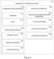
- the diagnostic interface device (110) includes a communication interface (210), a processing module (220), and a physical interface (230).
- the communication interface (210) allows the device (110) to communicate with the diagnostic server (160) and, optionally, the user device (140).
- the communication interface (210) includes an antenna (212) for allowing wireless communication over, for example, a Wi-Fi or Bluetooth network, and a port (214) for communicating over a wired connection, for example a USB connection.
- the processing module (220) allows instructions to be carried out by the diagnostic interface device (110).
- the processing module (220) includes a power supply (222) for providing the diagnostic interface device (110) with power, a main processor (224) for processing data, and a storage device (226) for storing data required for operation of the diagnostic interface device (110).
- the main processor (224) is implemented on an advanced reduced instruction set computing machine (ARM) processor.
- the physical interface (230) allows the diagnostic interface device (110) to connect to the on-board diagnostic (OBD) system (105) of the vehicle (130), typically via the diagnostic connection port (120).
- OBD on-board diagnostic
- Various communication protocols may be usable by different types of vehicles. Accordingly, a variety of protocols may be provided by the physical interface component (230).
- the physical interface component may include a controller area network (CAN) interface (232) for allowing communication over a CAN bus communication protocol, a K-line interface (234) for allowing communication with a vehicle using an International Standard Organization (ISO) 9141 K-Line communication protocol, a J1850 Variable Pulse Width (VPW) interface (236) for allowing communication over a Society of Automotive Engineers (SAE) J1850 VPW communication protocol, and a J1850 Pulse Width Modulation (PWM) interface (238) for allowing communication over a SAE J1850 PWM communication protocol.
- CAN controller area network
- K-line interface for allowing communication with a vehicle using an International Standard Organization (ISO) 9141 K-Line communication protocol
- J1850 Variable Pulse Width (VPW) interface (236) for allowing communication over a Society of Automotive Engineers (SAE) J1850 VPW communication protocol
- PWM Pulse Width Modulation
- the diagnostic interface device (110) includes functionality to allow a user to perform basic diagnostic functions with the OBD system. This may include reading fault codes, clearing fault codes, reading real-time values, reading ECU information, and controlling the flow of instructions.
- the diagnostic interface device may therefore be used to perform these basic diagnostic functions without the need to receive information from an outside source.
- the diagnostic device does not include functionality for performing more advanced analysis or actions, as will be appreciated from what follows.
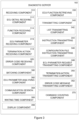
- the diagnostic server (160) may include a processor for executing the functions of components described below, which may be provided by hardware or by software units executing on the diagnostic server (160).
- the software units may be stored in a memory component and instructions may be provided to the processor to carry out the functionality of the described components. Some or all of the components may be provided by a software application downloadable onto and executable on the diagnostic server (160).
- the diagnostic server (160) includes a receiving component (310), an ECU function retrieving component (330), a transmitting component (340), a batching component (360), an ECU parameter analysing component (362), a communication session component (364), a waiting time component (366), a display component (368), and a command counting component (370).
- the ECU function retrieving component (330) is configured to retrieve ECU parameters executable by a specific ECU from a database associated with the diagnostic server.
- the batching component (360) is configured to batch instructions to be provided to the OBD system.
- the ECU parameter analysing component (362) is configured to analyse ECU parameters received from the OBD system, and to check whether a desired function may be performed with those ECU parameters.
- the communication session component (364) is configured to keep a communication session alive.
- the waiting time component (366) is configured to determine when a waiting time has expired before subsequent instructions may be sent to the diagnostic interface device.
- the display component (368) is configured to generate instructions to be sent to a display associated with the diagnostic interface device as part of batched instructions, and the command counting component (370) is configured to count executed commands to determine when a predetermined number of executions of a subset of a batch of instructions has been reached.
- the receiving component (310) includes various subcomponents to receive data from the diagnostic interface device and the OBD system.
- An ECU detail receiving component (312) is configured to receive ECU details from the diagnostic interface device.
- a function receiving component (314) is configured to receive an indication of a function received from the diagnostic interface device.
- An ECU parameter receiving component (316) is configured to receive ECU parameters from the OBD system.
- a termination action receiving component (318) is configured to receive a termination action from the diagnostic interface device, and an error code receiving component (320) is configured to receive an error code from the diagnostic interface device.
- the transmitting component (340) includes various subcomponents to transmit data to the diagnostic interface device and the OBD system.
- a list transmitting component (342) is configured to transmit a list of functions available for an applicable ECU to the diagnostic interface device.
- An instruction transmitting component (344) is configured to transmit batched instructions to the diagnostic interface device.
- a configuration file instruction transmitting component (346) is configured to transmit a configuration file instruction to the diagnostic interface device.
- An ECU parameter request transmitting component (348) is configured to transmit a request for ECU parameters to the OBD system.
- a termination action transmission component (350) is configured to transmit a termination action to the diagnostic interface device, and an error code message transmitting component (352) is configured to transmit an error code message to the diagnostic interface device.
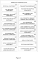
- the diagnostic interface device (110) includes a receiving component (410), a transmitting component (430), a configuration file loading component (450), a batching component (460), and a communication session component (470).
- the configuration file loading component (450) is configured to load a configuration file into memory.
- the configuration file readies timing parameters by setting it up for the relevant communication protocol.
- the batching component (460) is configured to batch data to be transmitted to the diagnostic server (160).
- the communication session component (470) is configured to keep a communication session alive and control the flow of instructions.
- the receiving component (410) includes various subcomponents to receive data from the diagnostic server (160) and the OBD system.
- a list receiving component (412) is configured to receive a list of functions executable by a relevant ECU from the diagnostic server (160).
- a user input receiving component (414) is configured to receive user input indicating which of the executable functions is to be provided to the OBD system.
- An instruction receiving component (416) is configured to receive batched instructions, including timing parameters, from the diagnostic server (160).
- a configuration file receiving component (418) is configured to receive an indication of a configuration file from the diagnostic server (160).
- An ECU parameter request receiving component (420) is configured to receive a request for ECU parameters from the diagnostic server (160), while an ECU parameter receiving component (422) is configured to receive ECU parameters from the OBD system.
- a termination action receiving component (424) is configured to receive a termination action from a user, and an error code receiving component (426) is configured to receive an error code form the OBD system.
- the transmitting component (430) includes various subcomponents to transmit data to the diagnostic server (160), the OBD system and the user device (140).
- a function transmitting component (432) is configured to transmit an indication of a function selected by a user to the diagnostic server (160).
- An OBD transmitting component (434) is configured to transmit every instruction received as part of a batch of instructions from the diagnostic server (160), to the OBD system.
- An ECU parameter request transmitting component (436) is configured to transmit a request for ECU parameters to the OBD system, while an ECU parameter transmitting component (438) is configured to transmit received ECU parameters to the diagnostic server (160).
- a user termination action component (440) is configured to transmit a user termination action indicator to the diagnostic server (160), and an error code transmitting component (442) is configured to transmit an error code indicator to the diagnostic server (160).
- a function completed transmitting component (444) is configured to transmit a function completed indicator to the diagnostic server.
- a display component (480) is configured to transmit details to be displayed on a display of the user device (140).
- Figure 5 shows a method (500) of transferring diagnostic commands to an on-board diagnostics (OBD) system of a vehicle using the diagnostic server (160) of Figure 3
- Figure 6 shows a method (600) of transferring diagnostic commands to an on-board diagnostics (OBD) system using the diagnostic interface device (110) of Figure 4
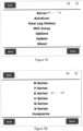
- Figures 7A to 7F shows screenshots taken from a display associated with the diagnostic interface device (110).
- the associated display is the display of the user device (140) in communication with the diagnostic interface device (110) via the web server (180).
- the methods (500, 600) as they are performed during testing of an engine coolant light of a vehicle is described below with reference to Figures 5 , 6 , and 7A to 7F .
- a user browses to the web server (180) of the diagnostic interface device (110) using their user device (140).
- Figure 7A is then displayed in the display of the user device (140).
- Figure 7B is displayed to the user.
- the user selects "K-series” (720), and is presented with the display of Figure 6C.
- the user selects "K1600GT” (730), which is the model of the relevant vehicle, in this case a motorbike.
- the diagnostic interface device (110) receives (602) the indication of the relevant ECU, and Figure 7D is then displayed to the user.
- the user selects "Engine Controller” (740), and is provided with the display in Figure 7E .
- the diagnostic interface device (110) transmits (604) the ECU details to the diagnostic server (160) over the Internet.
- the diagnostic server (160) receives (502) the ECU details, and retrieves (504) a list of functions executable by the specific ECU from a database associated therewith.
- the diagnostic server (160) transmits this list of functions to the diagnostic interface device (110).
- the diagnostic interface device (110) receives (606) the list of functions, and sends them to the user device (140) to be displayed on the display of the user device as shown in Figure 7F .
- the user may need to expand a subsection of the list, for example "BMSX Output Test" (760), so that a desired function in the list is displayed.
- a user wishes to test an engine coolant light and therefore selects the desired function, "Engine Coolant Light” (770).
- the diagnostic interface device receives (608) an indication thereof, and transmits (610) an indication of this function to the diagnostic server (160).
- the diagnostic server receives (508) the indication of the function.
- the diagnostic server transmits (510) a configuration file instruction to the diagnostic interface device (110), which receives (612) the instruction.
- the diagnostic interface device (110) then loads (614) the configuration file into memory. This readies timing parameters by setting them up for the specific communication protocol in use.
- the server transmits a batch of instructions to the diagnostic interface device (110), including a request (512) for ECU parameters associated with the specific function.
- Information to be displayed on the display associated with the diagnostic interface device (110) is also transmitted.
- a user option may also be provided to allow the user to select to continue with the method, or to cancel the method. If the user instructs the method to continue, it does so. Alternatively, if the user selects cancel, the method may immediately stop.
- the diagnostic interface device (110) receives (616) the request for ECU parameters and transmits (618) a request for the parameters to the OBD system (105).
- the ECU parameters are then received (620) and transmitted (622) to the diagnostic server (160). These parameters are batched together and sent in a batched format to the diagnostic server (160).
- the diagnostic server (160) receives (514), and analyses (516) the ECU parameters.
- the ECU parameters may vary depending on the type of function to be performed. Certain parameters may influence the possibility of executing a desired instruction. In the present example, the parameters are the revolutions per minute (RPM) of an engine of the vehicle, and any current fault codes of the OBD. Analyses of the ECU parameters includes determining that the RPM value is not zero, which means that the engine of the vehicle is running, and that any fault codes present are not relevant to the applicable function. The function may still be allowed to continue if fault codes are present that are not relevant to that function.
- RPM revolutions per minute
- ECU parameter analysis determines (518) that the parameters are not acceptable, an error message is transmitted (520) to the diagnostic interface device, and the method is stopped. If the parameters are determined (518) to be acceptable, the method may continue.
- the diagnostic server (160) batches a set of instructions to initiate a diagnostic session and execute the selected function, and transmits (522) the batch of instructions to the diagnostic interface device.
- the batch of instructions includes timing parameters specific to each instruction in the batch.
- the diagnostic server (160) then waits (524) for a certain time period. The time period may be included in the set of instructions, and be calculated to be sufficient for the set of instructions to be carried out by the diagnostic interface device (110), given network latency.
- the instructions may also include an instruction to repeat a subset of the batch of instructions a number of times.
- the diagnostic interface device (110) In order to perform a desired function, certain instructions need to be provided to the OBD system (105) in a specific order and within specific timeframes. Some procedures cannot be interrupted whilst being performed. By grouping and batching instructions so that groups of instructions and their breakouts are provided by the diagnostic interface device to the OBD system at the correct times and in the correct order, the diagnostic interface device (110) has the required instructions ready to transmit when required. This may prevent timeouts which would otherwise have occurred if the instructions were sent directly from the server to the OBD system over the open network.
- the diagnostic interface device (110) receives (624) the batched instructions, and transfers (626) the instructions according to the relevant timing parameters to the OBD system.
- the OBD system may then execute the instructions in the correct order and at the correct times.
- the diagnostic interface device (110) is operable to control the flow of instructions based on responses received from the OBD system (105). Depending on other actions currently being carried out by the vehicle, the OBD system may respond to a request from the diagnostic interface device (110) with, "I cannot perform your request now, please try later", or "I received your request but cannot respond now, please wait for my response". In the first case, the diagnostic interface device is operable to control the flow of instructions so as to wait and repeat the specific instruction again. In the second case, the diagnostic interface device is operable to wait one or more additional time periods for the response.
- the user (150) may be provided with a cancellation option on the display in order to terminate the function currently being executed. However, the exact procedure to terminate a function may not be straightforward. A series of instructions may be required to complete so as to safely disable a present function. If the user selects the cancellation option, the diagnostic interface device (110) receives (628) the user termination action, and transmits (630) a user termination instruction to the diagnostic server (160). If the diagnostic server (160) receives (526) such a termination instruction, it batches and transmits (528) the functions required to terminate the function to the diagnostic interface device.
- the termination functions may include a command to terminate the communication session, and an instruction to read any error codes. The batched set is handled in a similar manner to the batch including the original instruction, and are performed when provided to the OBD system by the diagnostic interface device. A message indicating that the function was terminated may be displayed on the display.
- the server may be configured to wait a certain amount of time before transferring the subsequent instructions. If the waiting time has been exceeded (530), the diagnostic server (160) will repeat and batch (522) a further set of instructions and send these to the diagnostic interface device, which again deals with the batch of instructions as described above.
- the waiting time will typically be determined to include the expected latency of the network.
- an error code is received (632) from the OBD system by the diagnostic interface device (110)
- the error code is transmitted (634) to the diagnostic server (160). If the diagnostic server (160) receives (534) an error code, it transmits (536) an error message to be displayed to the user on the display.
- the diagnostic interface device (110) transmits (638) a message to that effect to the diagnostic server (160).
- the diagnostic server (160) receives (538) such a message, and transmits (540) a message to the user device to display to the user that the function has completed successfully.
- timing parameters may include any one or more of a time required to execute a specific function, timing limitations of the communication protocol of the OBD system, and inter-byte and inter-packet gaps. If these timing parameters are not adhered to, transmission of data between the diagnostic interface device and vehicle OBD system may be unsuccessful. For this reason, batched instructions are transmitted to the diagnostic interface device, which in turn ensures that data is transmitted to the OBD system according to the relevant timing parameters. Instructions may then be transmitted in a suitable order and at the correct times to prevent a failure in communication, and the diagnostic interface device can also control the flow of instructions based on responses from the OBD system. While an OBD system is waiting for further instructions, the communication session component ensures that the communication session is kept alive. This prevents a time-out from occurring which would cause communication with the OBD to be lost.
- the diagnostic server may be configured to transmit a batch of termination instructions when this number of times has been reached.
- the diagnostic interface device may instruct the server of the number of times that a function has been performed, alternatively the server may be configured to determine the time required to perform the instruction the number of times, and to transmit a termination instruction if no further information has been received from the diagnostic interface device during that time.
- the display of the user device serves as a display and graphical user interface to the diagnostic interface device in the embodiment described above, by means of the user device connecting to the web server hosted on the diagnostic interface device.
- the display details are suitable for display on the display of the user device, and allows a user to interact with the displayed functions, buttons or the like. Displayed details may include a progress of a function, a status of the OBD or the function, information about a function, and the like.
- Information to be displayed may be contained in a batch of instructions, alternatively may be transmitted individually, for example the list of instructions executable by the ECU.
- the user device may provide a channel for the diagnostic interface device to connect to the diagnostic server.
- the diagnostic interface device may connect wirelessly or via a wired connection to the user device, and the user device may then facilitate communication of the diagnostic interface device with the diagnostic server over the open network.
- the user device may itself be the diagnostic interface device.
- the user device may then include a diagnostic port connector for connecting to a diagnostic connection port, or a diagnostic connection port may be connectable to the user device.
- the diagnostic interface device is incorporated into the OBD system of a vehicle and may always have a dedicated connection to the OBD system. Then, only a connection to the diagnostic server over the open network will be required for the method and system to be implemented.
- the user device may have an application installed thereon which is configured to, upon opening, access the web server on the diagnostic interface device.
- service functions may be any function normally performed in a workshop, including, but not limited to, calibration functions such as idle actuator calibration and throttle position sensor calibration, or adaptation clearing or reset functions.
- the service functions may include configuration functions such as a so-called “showroom” and “shipping” mode, in which certain vehicle functionality is enabled or disabled.
- Output tests such as fan or injector tests may also form part of the possible functions, as well as coding for certain constraints such as display units, light timing, and the like.
- diagnostic interface device Because all of the service functions are stored on the diagnostic server, there may not be a need to update the diagnostic interface device, particularly the diagnostic interface device firmware, when these parameters are changed. This may allow the addition, removal or altering of certain instructions without requiring direct access to all diagnostic interface devices. As a diagnostic interface device receives the possible functions from the diagnostic server before selecting a specific function, details of available functions may be independent of the diagnostic interface device. This also allows the diagnostic interface device to have minimal processing capability, as processing for the instructions to be provided to an OBD system, in particular batching, is performed at the diagnostic server. This may at least partially limits the cost of the diagnostic interface device.
- the present invention allows for communication with a vehicle OBD system from a diagnostic server, over an open communications network such as the internet, to a diagnostic interface device in connection with a vehicle OBD system.
- the batching of instructions allow communication with a diagnostic server over a relatively high latency communication network such as the Internet. This may allow the server to be located a long way from the vehicle, such as on a different continent.
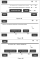
- Figure 8A to 8D shows additional screenshots of the display associated with the diagnostic interface device.
- Figure 8A shows information about an "Actuate Fuel Pump" function.
- the display includes a description (802) of the function, a warning (804), a button (806) to perform the action, and a button (808) to cancel the function.
- Figure 8B shows information about a "Start Bleed Test" function.
- a description (810) is displayed, as well as a button (812) to perform, and a button (814) to cancel the function.
- Figure 8C shows information about "RPM Limit” functions.
- Information (816) about the functions are displayed, as well as a "Remove RPM Limit” button (818) to remove an RPM limit, a “Set RPM Limit” button (820) to set an RPM limit, and a “Cancel” button (822) to cancel the function.
- Figure 8D shows a display after IABSCAN Output heading (824) was selected, and a list of functions falling under that heading expanded.
- Figure 9 illustrates an example of a diagnostic server (900) in which various aspects of the disclosure may be implemented.
- the diagnostic server (900) may be suitable for storing and executing computer program code.
- the various participants and elements in the previously described system diagrams may use any suitable number of subsystems or components of the diagnostic server (900) to facilitate the functions described herein.
- the diagnostic server (900) may include subsystems or components interconnected via a communication infrastructure (905) (for example, a communications bus, a cross-over bar device, or a network).
- the diagnostic server (900) may include one or more central processors (910) and at least one memory component in the form of computer-readable media. In some configurations, a number of processors may be provided and may be arranged to carry out calculations simultaneously.
- a number of diagnostic servers (900) may be provided in a distributed, cluster or cloud-based computing configuration and may provide software units arranged to manage and/or process data on behalf of remote devices.
- the memory components may include system memory (915), which may include read only memory (ROM) and random access memory (RAM).
- ROM read only memory
- RAM random access memory
- a basic input/output system (BIOS) may be stored in ROM.
- System software may be stored in the system memory (915) including operating system software.
- the memory components may also include secondary memory (920).
- the secondary memory (920) may include a fixed disk (921), such as a hard disk drive, and, optionally, one or more removable-storage interfaces (922) for removable-storage components (923).
- the removable-storage interfaces (922) may be in the form of removable-storage drives (for example, magnetic tape drives, optical disk drives, etc.) for corresponding removable storage-components (for example, a magnetic tape, an optical disk, etc.), which may be written to and read by the removable-storage drive.
- the removable-storage interfaces (922) may also be in the form of ports or sockets for interfacing with other forms of removable-storage components (923) such as a flash memory drive, external hard drive, or removable memory chip, etc.
- the diagnostic server (900) may include an external communications interface (930) for operation of the diagnostic server (900) in a networked environment enabling transfer of data between multiple diagnostic servers (900).
- Data transferred via the external communications interface (930) may be in the form of signals, which may be electronic, electromagnetic, optical, radio, or other types of signal.
- the external communications interface (930) may enable communication of data between the diagnostic server (900) and other diagnostic servers including servers and external storage facilities. Web services may be accessible by the diagnostic server (900) via the communications interface (930).
- the external communications interface (930) may also enable other forms of communication to and from the diagnostic server (900) including, voice communication, near field communication, radio frequency communications, such as Bluetooth TM , etc.
- the computer-readable media in the form of the various memory components may provide storage of computer-executable instructions, data structures, program modules, software units and other data.
- a computer program product may be provided by a computer-readable medium having stored computer-readable program code executable by the central processor (910).
- a computer program product may be provided by a non-transient computer-readable medium, or may be provided via a signal or other transient means via the communications interface (930).
- Interconnection via the communication infrastructure (905) allows the central processor (910) to communicate with each subsystem or component and to control the execution of instructions from the memory components, as well as the exchange of information between subsystems or components.
- Peripherals such as printers, scanners, cameras, or the like
- input/output (I/O) devices such as a mouse, touchpad, keyboard, microphone, and the like
- I/O controller 935
- These components may be connected to the diagnostic server (900) by any number of means known in the art, such as a serial port.
- One or more monitors (945) may be coupled via a display or video adapter (940) to the diagnostic server (900).
- a software unit is implemented with a computer program product comprising a non-transient computer-readable medium containing computer program code, which can be executed by a processor for performing any or all of the steps, operations, or processes described.
- Software units or functions described in this application may be implemented as computer program code using any suitable computer language such as, for example, Java TM , C++, or Perl TM using, for example, conventional or object-oriented techniques.
- the computer program code may be stored as a series of instructions, or commands on a non-transitory computer-readable medium, such as a random access memory (RAM), a read-only memory (ROM), a magnetic medium such as a hard-drive, or an optical medium such as a CD-ROM. Any such computer-readable medium may also reside on or within a single computational apparatus, and may be present on or within different computational apparatuses within a system or network.
- a non-transitory computer-readable medium such as a random access memory (RAM), a read-only memory (ROM), a magnetic medium such as a hard-drive, or an optical medium such as a CD-ROM.
- RAM random access memory
- ROM read-only memory
- magnetic medium such as a hard-drive
- optical medium such as a CD-ROM.
Landscapes
- Engineering & Computer Science (AREA)
- Physics & Mathematics (AREA)
- General Physics & Mathematics (AREA)
- Theoretical Computer Science (AREA)
- General Engineering & Computer Science (AREA)
- Databases & Information Systems (AREA)
- Signal Processing (AREA)
- Computer Hardware Design (AREA)
- Computer Networks & Wireless Communication (AREA)
- Quality & Reliability (AREA)
- Automation & Control Theory (AREA)
- Computational Linguistics (AREA)
- Human Computer Interaction (AREA)
- Data Mining & Analysis (AREA)
- Small-Scale Networks (AREA)
- Debugging And Monitoring (AREA)
- Computer And Data Communications (AREA)
Claims (15)
- Procédé de transfert de commandes de diagnostic à un système de diagnostic embarqué (OBD) (105) d'un véhicule (130), le procédé étant exécuté par un serveur de diagnostic (160) qui est en communication de données avec un dispositif d'interface de diagnostic (110) sur un réseau ouvert (190), le dispositif d'interface de diagnostic (110) étant connecté au système OBD du véhicule (105) au moyen d'une connexion dédiée, le procédé comprenant les étapes suivantes :recevoir (502), depuis le dispositif d'interface de diagnostic (110), les détails d'une unité de contrôle électronique (ECU) associée au système OBD (105) ;extraire (504) d'une liste de fonctions exécutables par l'ECU à partir d'une base de données,transmettre (506), au dispositif d'interface de diagnostic (110), la liste des fonctions exécutables par l'ECU ;recevoir (508), depuis le dispositif d'interface de diagnostic (110), une indication d'une fonction sélectionnée dans la liste des fonctions exécutables ; ettransmettre (522) un lot d'instructions au dispositif d'interface de diagnostic (110) pour lancer une session de diagnostic et exécuter la fonction sélectionnée, le lot d'instructions comprenant des paramètres de synchronisation spécifiques à chaque instruction dans le lot pour donner pour instruction au dispositif d'interface de diagnostic (110) de transférer chaque instruction dans le lot au système OBD du véhicule (105) sur la connexion dédiée conformément aux paramètres de synchronisation, les paramètres de synchronisation comprenant des limitations de synchronisation d'un protocole de communication du système OBD (105).
- Procédé tel que revendiqué dans la revendication 1, comprenant une étape de transmission (510) d'un autre lot d'instructions au dispositif d'interface de diagnostic (110), l'autre lot d'instructions comprenant une instruction de fichier de configuration pour faciliter la préparation des paramètres de synchronisation pour la fonction.
- Procédé tel que revendiqué dans la revendication 1 ou la revendication 2, comprenant les étapes suivantes :transmettre un lot initial d'instructions au dispositif d'interface de diagnostic, le lot initial d'instructions comprenant une demande (512) de paramètres ECU ;recevoir (514) les paramètres ECU demandés ; etanalyser (516) les paramètres ECU pour confirmer qu'ils permettent d'exécuter la fonction avant de transmettre (522) le lot d'instructions pour l'exécution de la fonction sélectionnée.
- Procédé tel que revendiqué dans l'une quelconque des revendications précédentes, dans lequel le lot d'instructions comprend une instruction de maintien en activité d'une session de communication.
- Procédé tel que revendiqué dans l'une quelconque des revendications précédentes, comprenant l'étape suivante :
en réponse à la réception (526) d'un indicateur d'action de cessation de l'utilisateur, transmettre (528) des instructions pour faciliter la cessation de la fonction au dispositif d'interface de diagnostic (110). - Procédé tel que revendiqué dans l'une quelconque des revendications précédentes, comprenant l'étape suivante :en réponse à l'expiration d'un temps d'attente prédéterminé (530) avant l'exécution d'une action de cessation de l'utilisateur, transmettre (522) d'autres instructions au dispositif d'interface de diagnostic (110) ;en réponse à la réception (534) d'un code d'erreur en provenance du dispositif d'interface de diagnostic (110), transmettre un message d'erreur au dispositif d'interface de diagnostic (110) ; eten réponse à la réception (538) d'un indicateur d'achèvement de fonction, transmettre (540) un message d'achèvement de fonction au dispositif d'interface de diagnostic (110).
- Procédé tel que revendiqué dans l'une quelconque des revendications précédentes, dans lequel les paramètres de synchronisation comprennent en outre un ou plusieurs des éléments suivants : le temps nécessaire à l'exécution de la fonction, et les écarts inter-octets et inter-paquets.
- Procédé tel que revendiqué dans l'une quelconque des revendications précédentes, dans lequel le lot d'instructions comprend une collection de commandes pour lancer une session de diagnostic, pour exécuter la fonction spécifique, pour attendre (524) pendant un certain temps à moins qu'une action de cessation de l'utilisateur n'ait été effectuée, et une instruction pour répéter un sous-ensemble du lot un nombre de fois prédéterminé.
- Procédé de transfert de commandes de diagnostic à un système de diagnostic embarqué (OBD) (105) d'un véhicule (130), le procédé étant exécuté par un dispositif d'interface de diagnostic (110) connecté au système OBD (105) par l'intermédiaire d'une connexion dédiée et en communication de données avec un serveur de diagnostic (160) sur un réseau ouvert (190), le procédé comprenant les étapes suivantes :transmettre (604), au serveur de diagnostic (160), les détails d'un ECU associé au système OBD ;recevoir (606), depuis le serveur de diagnostic (160), une liste de fonctions exécutables par l'ECU ;recevoir (608), de la part d'un utilisateur, une indication d'une fonction de la liste à fournir à l'OBD ;transmettre (610), au serveur de diagnostic (160), l'indication de la fonction ;recevoir (624) un lot d'instructions depuis le serveur de diagnostic (160) pour initier une session de diagnostic et exécuter la fonction sélectionnée, le lot d'instructions comprenant des paramètres de synchronisation spécifiques à chaque instruction dans le lot pour donner pour instruction au dispositif d'interface de diagnostic (110) de transférer chaque instruction contenue dans le lot au système OBD du véhicule (105) conformément aux paramètres de synchronisation comprenant des limitations de synchronisation d'un protocole de communication du système OBD (105) ; ettransférer (626) chaque instruction du lot au système OBD (105) conformément aux paramètres de synchronisation.
- Procédé tel que revendiqué dans la revendication 9, comprenant les étapes suivantes :recevoir (612) une instruction de fichier de configuration depuis le serveur de diagnostic (160), le fichier de configuration facilitant la préparation des paramètres de synchronisation pour l'instruction ; etcharger (614) le fichier de configuration dans une mémoire.
- Procédé tel que revendiqué dans la revendication 9 ou la revendication 10, comprenant les étapes suivantes :recevoir (616), depuis le serveur de diagnostic (160), un lot initial d'instructions, le lot initial comprenant une demande de paramètres ECU ;transmettre (618) une demande de paramètres ECU au système OBD (105) ;recevoir (620) des paramètres ECU en provenance du système OBD (105) ; ettransmettre (622) les paramètres ECU au serveur de diagnostic (160) sous forme de lot.
- Procédé tel que revendiqué dans l'une quelconque des revendications 9 à 11, comprenant les étapes suivantes :en réponse (628) à la réception d'une action de cessation de l'utilisateur, transmettre (630) un indicateur de cessation de l'utilisateur au serveur de diagnostic (160) ;en réponse (632) à la réception d'un code d'erreur du système OBD (105), transmettre le code d'erreur au serveur de diagnostic (160) ; eten réponse (636) à la reconnaissance de l'achèvement d'une fonction, transmettre (638) un indicateur d'achèvement de fonction au serveur de diagnostic (160).
- Procédé tel que revendiqué dans l'une quelconque des revendications 9 à 12, comprenant l'étape suivante : en réponse à la réception de détails à afficher sur un écran associé au dispositif d'interface de diagnostic dans le cadre des instructions en lots, envoyer les détails à l'écran.
- Procédé tel que revendiqué dans l'une quelconque des revendications 9 à 13, comprenant les étapes suivantes :en réponse au système OBD (105) qui répond à une instruction par une réponse indiquant que l'instruction ne peut pas être exécutée maintenant, attendre une durée prédéterminée et répéter l'instruction spécifique ; eten réponse au système OBD (105) qui répond à une instruction par une réponse indiquant que l'instruction a été reçue mais que le système OBD (105) ne peut pas répondre maintenant, attendre la réponse pendant une durée prédéterminée.
- Dispositif d'interface de diagnostic (110) permettant de transférer des commandes de diagnostic à un système de diagnostic embarqué (OBD)(105) d'un véhicule (130), le dispositif comprenant :une interface physique (230) configurée pour communiquer avec le système OBD (105) sur un réseau dédié ;une interface de communication (210) configurée pour communiquer avec un serveur de diagnostic (160) sur un réseau ouvert (190) ; etun module de traitement (220), où le module de traitement (220) comprend :un composant de transmission de paramètre ECU (438) configuré pour transmettre au serveur de diagnostic (160) les détails d'un ECU associé au système OBD ;un composant de réception de liste (412) configuré pour recevoir du serveur de diagnostic (160) une liste de fonctions exécutables par l'ECU ;un composant d'entrée utilisateur (414) configuré pour recevoir, de la part d'un utilisateur, une indication d'une fonction de la liste à fournir au système OBD (105) ;un composant de transmission de fonction (432) configuré pour transmettre l'indication de la fonction au serveur (160) ;un composant de réception d'instructions (416) configuré pour recevoir un lot d'instructions depuis le serveur de diagnostic (160), pour initier une session de diagnostic et exécuter la fonction sélectionnée, le lot d'instructions comprenant des paramètres de synchronisation spécifiques à chaque instruction du lot afin de donner pour instruction au dispositif d'interface de diagnostic (110) de transférer chaque instruction du lot au système OBD du véhicule (105) conformément aux paramètres de synchronisation comprenant les limitations de synchronisation d'un protocole de communication du système OBD ; etun composant de transfert de système OBD (434) configuré pour transférer chaque instruction du lot au système OBD (105) conformément aux paramètres de synchronisation.
Applications Claiming Priority (2)
| Application Number | Priority Date | Filing Date | Title |
|---|---|---|---|
| ZA201503489 | 2015-05-19 | ||
| PCT/IB2016/052826 WO2016185360A1 (fr) | 2015-05-19 | 2016-05-16 | Système et procédé de transfert de commandes de diagnostic à un véhicule |
Publications (4)
| Publication Number | Publication Date |
|---|---|
| EP3297880A1 EP3297880A1 (fr) | 2018-03-28 |
| EP3297880A4 EP3297880A4 (fr) | 2018-06-20 |
| EP3297880B1 true EP3297880B1 (fr) | 2024-09-25 |
| EP3297880C0 EP3297880C0 (fr) | 2024-09-25 |
Family
ID=57319531
Family Applications (1)
| Application Number | Title | Priority Date | Filing Date |
|---|---|---|---|
| EP16795981.6A Active EP3297880B1 (fr) | 2015-05-19 | 2016-05-16 | Système et procédé de transfert de commandes de diagnostic à un véhicule |
Country Status (6)
| Country | Link |
|---|---|
| US (1) | US10621797B2 (fr) |
| EP (1) | EP3297880B1 (fr) |
| CN (1) | CN107848522B (fr) |
| ES (1) | ES2988340T3 (fr) |
| WO (1) | WO2016185360A1 (fr) |
| ZA (1) | ZA201707851B (fr) |
Families Citing this family (28)
| Publication number | Priority date | Publication date | Assignee | Title |
|---|---|---|---|---|
| TWM522269U (zh) * | 2016-01-14 | 2016-05-21 | 橋牧科技股份有限公司 | 車輛節氣門診斷裝置 |
| US10529150B2 (en) * | 2016-06-30 | 2020-01-07 | Aviation Systems LLC | Remote data loading for configuring wireless communication unit for communicating engine data |
| US20180032421A1 (en) * | 2016-07-29 | 2018-02-01 | Wipro Limited | Method and system for debugging automotive applications in an electronic control unit of an automobile |
| EP3422128A4 (fr) * | 2017-04-07 | 2019-11-20 | Launch Tech Co., Ltd. | Procédé et appareil destinés à être utilisés dans le diagnostic à distance de véhicule |
| US11295560B2 (en) * | 2018-08-01 | 2022-04-05 | Ford Global Technologies, Llc | Cloud-managed validation and execution for diagnostic requests |
| KR102529392B1 (ko) * | 2018-11-19 | 2023-05-08 | 현대자동차 주식회사 | 전방 충돌 방지 보조 성능 검사 시스템 및 그 방법 |
| CN109617899A (zh) * | 2018-12-28 | 2019-04-12 | 深圳市元征科技股份有限公司 | 一种数据传输方法以及系统 |
| CN113060081A (zh) * | 2019-12-31 | 2021-07-02 | 陕西重型汽车有限公司 | 一种基于手机app的中央充放气调试系统及方法 |
| US12327439B2 (en) * | 2020-02-26 | 2025-06-10 | Innova Electronics Corporation | Vehicle diagnostic system and related methodology deployable at vehicle service facility |
| GB2592650A (en) * | 2020-03-05 | 2021-09-08 | Jaguar Land Rover Ltd | Vehicle diagnostics |
| USD960129S1 (en) | 2020-06-09 | 2022-08-09 | Geotab Inc. | Case for electronic communication device |
| US11336727B2 (en) * | 2020-08-18 | 2022-05-17 | Geotab Inc. | Specialized casing unit detection for asset tracking devices |
| US11649775B2 (en) * | 2020-09-24 | 2023-05-16 | Kohler Co. | Analog controller for electronic throttle body |
| CN112965463B (zh) * | 2021-02-07 | 2023-02-03 | 上汽大通汽车有限公司 | 远程诊断系统及远程诊断方法 |
| CN113485310B (zh) * | 2021-08-20 | 2021-12-14 | 深圳市星卡科技有限公司 | 汽车远程诊断方法、装置和计算机设备 |
| CN113448320B (zh) * | 2021-08-30 | 2021-11-30 | 深圳市星卡科技有限公司 | 汽车双远程诊断方法、系统、装置和计算机设备 |
| CN114328175A (zh) * | 2021-11-22 | 2022-04-12 | 江铃汽车股份有限公司 | 一种车辆特殊流程配置方法、装置、存储介质及系统 |
| CN114137937B (zh) * | 2021-11-25 | 2024-01-26 | 北京经纬恒润科技股份有限公司 | 一种自动化诊断功能测试方法及系统 |
| US12292807B2 (en) * | 2021-12-08 | 2025-05-06 | Hcl Technologies Limited | Method and system for performing dataload protocol operation testing in an avionics unit |
| US12210342B2 (en) * | 2022-03-27 | 2025-01-28 | Third Wave Automation, Inc. | Methods and apparatus for supporting remote control operation of devices taking into consideration communications latency, environmental conditions, and/or a task to be performed |
| CN115190144A (zh) * | 2022-06-23 | 2022-10-14 | 深圳市易孔立出软件开发有限公司 | 数据获取方法、系统、装置、终端设备及存储介质 |
| CN116233813B (zh) * | 2023-02-17 | 2025-04-11 | 武汉锐科控制系统有限公司 | 提高手机与车机之间数据传输的方法 |
| CN116149302B (zh) * | 2023-04-10 | 2024-10-01 | 北斗星通智联科技有限责任公司 | 车辆诊断测试方法、装置、电子设备及存储介质 |
| CN116224976B (zh) * | 2023-05-08 | 2023-08-25 | 北京集度科技有限公司 | 测试方法及装置 |
| JP2025174028A (ja) * | 2024-05-16 | 2025-11-28 | カワサキモータース株式会社 | 乗物 |
| US20250363022A1 (en) * | 2024-05-24 | 2025-11-27 | Advantest Test Solutions, Inc. | Testing systems and methods with cross-platform bridge components |
| USD1112107S1 (en) * | 2024-11-12 | 2026-02-10 | Geotab Inc. | Electronic control unit housing |
| USD1112108S1 (en) * | 2024-11-22 | 2026-02-10 | Geotab Inc. | Rugged electronic control unit housing |
Family Cites Families (9)
| Publication number | Priority date | Publication date | Assignee | Title |
|---|---|---|---|---|
| AU2001283140B2 (en) * | 2000-08-18 | 2005-07-28 | Nnt, Inc. | System, method and computer program product for remote vehicle diagnostics, monitoring, configuring and reprogramming |
| US7092803B2 (en) | 2000-08-18 | 2006-08-15 | Idsc Holdings, Llc | Remote monitoring, configuring, programming and diagnostic system and method for vehicles and vehicle components |
| JP3721089B2 (ja) * | 2001-03-01 | 2005-11-30 | 株式会社日立製作所 | 車両診断システム及び該システムを用いた自動車 |
| JP4069836B2 (ja) * | 2002-10-11 | 2008-04-02 | 株式会社デンソー | 車両用電子制御装置,電子制御ユニット,プログラム及び記録媒体 |
| US8352115B2 (en) * | 2009-06-30 | 2013-01-08 | GM Global Technology Operations LLC | Methods and apparatus for initiating service sessions between vehicles and service providers |
| CN202472295U (zh) * | 2012-03-01 | 2012-10-03 | 黄颂晖 | 一种机动车远程控制和交互装置 |
| US20130246135A1 (en) | 2012-03-14 | 2013-09-19 | Zhenrong Wang | System, device and method of remote vehicle diagnostics based service for vehicle owners |
| US8768565B2 (en) | 2012-05-23 | 2014-07-01 | Enterprise Holdings, Inc. | Rental/car-share vehicle access and management system and method |
| CA2868573C (fr) * | 2013-10-24 | 2017-09-12 | Alldata Llc | Systemes et procedes de diagnostic de vehicule |
-
2016
- 2016-05-16 WO PCT/IB2016/052826 patent/WO2016185360A1/fr not_active Ceased
- 2016-05-16 US US15/575,202 patent/US10621797B2/en active Active
- 2016-05-16 CN CN201680042715.0A patent/CN107848522B/zh active Active
- 2016-05-16 EP EP16795981.6A patent/EP3297880B1/fr active Active
- 2016-05-16 ES ES16795981T patent/ES2988340T3/es active Active
-
2017
- 2017-11-20 ZA ZA2017/07851A patent/ZA201707851B/en unknown
Also Published As
| Publication number | Publication date |
|---|---|
| EP3297880A1 (fr) | 2018-03-28 |
| ES2988340T3 (es) | 2024-11-20 |
| EP3297880A4 (fr) | 2018-06-20 |
| US10621797B2 (en) | 2020-04-14 |
| US20180151003A1 (en) | 2018-05-31 |
| WO2016185360A1 (fr) | 2016-11-24 |
| CN107848522A (zh) | 2018-03-27 |
| CN107848522B (zh) | 2020-07-17 |
| EP3297880C0 (fr) | 2024-09-25 |
| ZA201707851B (en) | 2020-07-29 |
Similar Documents
| Publication | Publication Date | Title |
|---|---|---|
| EP3297880B1 (fr) | Système et procédé de transfert de commandes de diagnostic à un véhicule | |
| CN102072822B (zh) | 车辆诊断装置 | |
| CN113960991B (zh) | 车辆故障诊断系统、方法、装置、片上系统芯片及车辆 | |
| CN108803577B (zh) | 一种诊断方法、上位机及下位机 | |
| CN111198790B (zh) | 机器人测试方法、机器人测试装置及机器人 | |
| CN111506047B (zh) | 车辆诊断方法、装置及存储介质 | |
| CN112740627A (zh) | 车辆远程诊断方法及系统 | |
| US7334041B2 (en) | Vehicle communications interface | |
| CN104111844A (zh) | 在移动终端内安装应用程序的方法及系统 | |
| US12190656B2 (en) | Method for vehicle diagnostics, diagnostic connector, and diagnostic device | |
| CN114900390B (zh) | 数据传输方法、装置、电子设备及存储介质 | |
| CN112829525A (zh) | 一种胎压传感器匹配方法、装置、系统及设备 | |
| CN111913472A (zh) | 车辆诊断设备的工作模式控制方法及相关设备 | |
| US20220324395A1 (en) | Apparatus for diagnostics communication error of vehicle, system having the same, and method thereof | |
| CN118018978A (zh) | 基于车辆诊断的多通道的通信方法、系统及电子设备 | |
| US20250286750A1 (en) | Communication interaction method, apparatus, device, and storage medium | |
| CN116736823A (zh) | 跨平台的控制器硬件在环测试方法、装置及系统 | |
| CN117608622A (zh) | 蓝牙模块升级方法、系统、蓝牙设备及存储介质 | |
| CN114442590A (zh) | 车辆诊断方法、设备、诊断通信装置、服务器及存储介质 | |
| US11171857B2 (en) | Identifying an electronic device connected to a communication network that has XCP enabled | |
| CN114003018A (zh) | 一种车辆诊断方法及相关装置 | |
| CN118660311B (zh) | 车载无线网络测试方法、系统、电子设备及存储介质 | |
| US20260001222A1 (en) | Robot diagnosis apparatus and method thereof | |
| CN111164624B (zh) | 用于车辆的处理单元 | |
| CN120370879A (zh) | 通信协议类型检测方法、装置、电子设备及存储介质 |
Legal Events
| Date | Code | Title | Description |
|---|---|---|---|
| STAA | Information on the status of an ep patent application or granted ep patent |
Free format text: STATUS: THE INTERNATIONAL PUBLICATION HAS BEEN MADE |
|
| PUAI | Public reference made under article 153(3) epc to a published international application that has entered the european phase |
Free format text: ORIGINAL CODE: 0009012 |
|
| STAA | Information on the status of an ep patent application or granted ep patent |
Free format text: STATUS: REQUEST FOR EXAMINATION WAS MADE |
|
| 17P | Request for examination filed |
Effective date: 20171207 |
|
| AK | Designated contracting states |
Kind code of ref document: A1 Designated state(s): AL AT BE BG CH CY CZ DE DK EE ES FI FR GB GR HR HU IE IS IT LI LT LU LV MC MK MT NL NO PL PT RO RS SE SI SK SM TR |
|
| AX | Request for extension of the european patent |
Extension state: BA ME |
|
| A4 | Supplementary search report drawn up and despatched |
Effective date: 20180518 |
|
| RIC1 | Information provided on ipc code assigned before grant |
Ipc: G07C 5/00 20060101AFI20180514BHEP Ipc: B60W 10/00 20060101ALI20180514BHEP Ipc: H04L 29/08 20060101ALI20180514BHEP Ipc: G06F 11/00 20060101ALI20180514BHEP |
|
| DAV | Request for validation of the european patent (deleted) | ||
| DAX | Request for extension of the european patent (deleted) | ||
| STAA | Information on the status of an ep patent application or granted ep patent |
Free format text: STATUS: EXAMINATION IS IN PROGRESS |
|
| 17Q | First examination report despatched |
Effective date: 20210406 |
|
| REG | Reference to a national code |
Ref country code: DE Ref legal event code: R079 Free format text: PREVIOUS MAIN CLASS: B60W0010000000 Ipc: H04L0009400000 Ref document number: 602016089576 Country of ref document: DE |
|
| RIC1 | Information provided on ipc code assigned before grant |
Ipc: H04W 4/44 20180101ALI20240320BHEP Ipc: G06F 11/22 20060101ALI20240320BHEP Ipc: G05B 23/02 20060101ALI20240320BHEP Ipc: G07C 5/00 20060101ALI20240320BHEP Ipc: H04L 9/40 20220101AFI20240320BHEP Ipc: G07C 5/08 20060101ALI20240320BHEP Ipc: G06F 16/903 20190101ALI20240320BHEP |
|
| GRAP | Despatch of communication of intention to grant a patent |
Free format text: ORIGINAL CODE: EPIDOSNIGR1 |
|
| STAA | Information on the status of an ep patent application or granted ep patent |
Free format text: STATUS: GRANT OF PATENT IS INTENDED |
|
| INTG | Intention to grant announced |
Effective date: 20240426 |
|
| GRAS | Grant fee paid |
Free format text: ORIGINAL CODE: EPIDOSNIGR3 |
|
| GRAA | (expected) grant |
Free format text: ORIGINAL CODE: 0009210 |
|
| STAA | Information on the status of an ep patent application or granted ep patent |
Free format text: STATUS: THE PATENT HAS BEEN GRANTED |
|
| AK | Designated contracting states |
Kind code of ref document: B1 Designated state(s): AL AT BE BG CH CY CZ DE DK EE ES FI FR GB GR HR HU IE IS IT LI LT LU LV MC MK MT NL NO PL PT RO RS SE SI SK SM TR |
|
| REG | Reference to a national code |
Ref country code: GB Ref legal event code: FG4D |
|
| REG | Reference to a national code |
Ref country code: CH Ref legal event code: EP |
|
| REG | Reference to a national code |
Ref country code: DE Ref legal event code: R096 Ref document number: 602016089576 Country of ref document: DE |
|
| REG | Reference to a national code |
Ref country code: IE Ref legal event code: FG4D |
|
| U01 | Request for unitary effect filed |
Effective date: 20241004 |
|
| REG | Reference to a national code |
Ref country code: ES Ref legal event code: FG2A Ref document number: 2988340 Country of ref document: ES Kind code of ref document: T3 Effective date: 20241120 |
|
| U07 | Unitary effect registered |
Designated state(s): AT BE BG DE DK EE FI FR IT LT LU LV MT NL PT RO SE SI Effective date: 20241028 |
|
| PG25 | Lapsed in a contracting state [announced via postgrant information from national office to epo] |
Ref country code: NO Free format text: LAPSE BECAUSE OF FAILURE TO SUBMIT A TRANSLATION OF THE DESCRIPTION OR TO PAY THE FEE WITHIN THE PRESCRIBED TIME-LIMIT Effective date: 20241225 |
|
| PG25 | Lapsed in a contracting state [announced via postgrant information from national office to epo] |
Ref country code: GR Free format text: LAPSE BECAUSE OF FAILURE TO SUBMIT A TRANSLATION OF THE DESCRIPTION OR TO PAY THE FEE WITHIN THE PRESCRIBED TIME-LIMIT Effective date: 20241226 |
|
| PG25 | Lapsed in a contracting state [announced via postgrant information from national office to epo] |
Ref country code: RS Free format text: LAPSE BECAUSE OF FAILURE TO SUBMIT A TRANSLATION OF THE DESCRIPTION OR TO PAY THE FEE WITHIN THE PRESCRIBED TIME-LIMIT Effective date: 20241225 |
|
| PG25 | Lapsed in a contracting state [announced via postgrant information from national office to epo] |
Ref country code: RS Free format text: LAPSE BECAUSE OF FAILURE TO SUBMIT A TRANSLATION OF THE DESCRIPTION OR TO PAY THE FEE WITHIN THE PRESCRIBED TIME-LIMIT Effective date: 20241225 Ref country code: NO Free format text: LAPSE BECAUSE OF FAILURE TO SUBMIT A TRANSLATION OF THE DESCRIPTION OR TO PAY THE FEE WITHIN THE PRESCRIBED TIME-LIMIT Effective date: 20241225 Ref country code: GR Free format text: LAPSE BECAUSE OF FAILURE TO SUBMIT A TRANSLATION OF THE DESCRIPTION OR TO PAY THE FEE WITHIN THE PRESCRIBED TIME-LIMIT Effective date: 20241226 |
|
| PG25 | Lapsed in a contracting state [announced via postgrant information from national office to epo] |
Ref country code: IS Free format text: LAPSE BECAUSE OF FAILURE TO SUBMIT A TRANSLATION OF THE DESCRIPTION OR TO PAY THE FEE WITHIN THE PRESCRIBED TIME-LIMIT Effective date: 20250125 |
|
| PG25 | Lapsed in a contracting state [announced via postgrant information from national office to epo] |
Ref country code: SM Free format text: LAPSE BECAUSE OF FAILURE TO SUBMIT A TRANSLATION OF THE DESCRIPTION OR TO PAY THE FEE WITHIN THE PRESCRIBED TIME-LIMIT Effective date: 20240925 |
|
| PG25 | Lapsed in a contracting state [announced via postgrant information from national office to epo] |
Ref country code: PL Free format text: LAPSE BECAUSE OF FAILURE TO SUBMIT A TRANSLATION OF THE DESCRIPTION OR TO PAY THE FEE WITHIN THE PRESCRIBED TIME-LIMIT Effective date: 20240925 Ref country code: CZ Free format text: LAPSE BECAUSE OF FAILURE TO SUBMIT A TRANSLATION OF THE DESCRIPTION OR TO PAY THE FEE WITHIN THE PRESCRIBED TIME-LIMIT Effective date: 20240925 |
|
| PG25 | Lapsed in a contracting state [announced via postgrant information from national office to epo] |
Ref country code: SK Free format text: LAPSE BECAUSE OF FAILURE TO SUBMIT A TRANSLATION OF THE DESCRIPTION OR TO PAY THE FEE WITHIN THE PRESCRIBED TIME-LIMIT Effective date: 20240925 |
|
| U20 | Renewal fee for the european patent with unitary effect paid |
Year of fee payment: 10 Effective date: 20250328 |
|
| PGFP | Annual fee paid to national office [announced via postgrant information from national office to epo] |
Ref country code: ES Payment date: 20250605 Year of fee payment: 10 |
|
| PLBE | No opposition filed within time limit |
Free format text: ORIGINAL CODE: 0009261 |
|
| STAA | Information on the status of an ep patent application or granted ep patent |
Free format text: STATUS: NO OPPOSITION FILED WITHIN TIME LIMIT |
|
| 26N | No opposition filed |
Effective date: 20250626 |
|
| REG | Reference to a national code |
Ref country code: CH Ref legal event code: H13 Free format text: ST27 STATUS EVENT CODE: U-0-0-H10-H13 (AS PROVIDED BY THE NATIONAL OFFICE) Effective date: 20251223 |
|
| PG25 | Lapsed in a contracting state [announced via postgrant information from national office to epo] |
Ref country code: HR Free format text: LAPSE BECAUSE OF FAILURE TO SUBMIT A TRANSLATION OF THE DESCRIPTION OR TO PAY THE FEE WITHIN THE PRESCRIBED TIME-LIMIT Effective date: 20240925 |
|
| PG25 | Lapsed in a contracting state [announced via postgrant information from national office to epo] |
Ref country code: CH Free format text: LAPSE BECAUSE OF NON-PAYMENT OF DUE FEES Effective date: 20250531 |
|
| PG25 | Lapsed in a contracting state [announced via postgrant information from national office to epo] |
Ref country code: MC Free format text: LAPSE BECAUSE OF FAILURE TO SUBMIT A TRANSLATION OF THE DESCRIPTION OR TO PAY THE FEE WITHIN THE PRESCRIBED TIME-LIMIT Effective date: 20240925 |
|
| PGFP | Annual fee paid to national office [announced via postgrant information from national office to epo] |
Ref country code: GB Payment date: 20260330 Year of fee payment: 11 |
|
| PG25 | Lapsed in a contracting state [announced via postgrant information from national office to epo] |
Ref country code: IE Free format text: LAPSE BECAUSE OF NON-PAYMENT OF DUE FEES Effective date: 20250516 |