EP3298095B1 - Matière particulaire adhésive appliquée sélectivement sur des substrats non métalliques - Google Patents
Matière particulaire adhésive appliquée sélectivement sur des substrats non métalliques Download PDFInfo
- Publication number
- EP3298095B1 EP3298095B1 EP16724196.7A EP16724196A EP3298095B1 EP 3298095 B1 EP3298095 B1 EP 3298095B1 EP 16724196 A EP16724196 A EP 16724196A EP 3298095 B1 EP3298095 B1 EP 3298095B1
- Authority
- EP
- European Patent Office
- Prior art keywords
- adhesive particulate
- substrate
- adhesive
- laser
- particulate
- Prior art date
- Legal status (The legal status is an assumption and is not a legal conclusion. Google has not performed a legal analysis and makes no representation as to the accuracy of the status listed.)
- Active
Links
Images


Classifications
-
- C—CHEMISTRY; METALLURGY
- C09—DYES; PAINTS; POLISHES; NATURAL RESINS; ADHESIVES; COMPOSITIONS NOT OTHERWISE PROVIDED FOR; APPLICATIONS OF MATERIALS NOT OTHERWISE PROVIDED FOR
- C09J—ADHESIVES; NON-MECHANICAL ASPECTS OF ADHESIVE PROCESSES IN GENERAL; ADHESIVE PROCESSES NOT PROVIDED FOR ELSEWHERE; USE OF MATERIALS AS ADHESIVES
- C09J5/00—Adhesive processes in general; Adhesive processes not provided for elsewhere, e.g. relating to primers
- C09J5/06—Adhesive processes in general; Adhesive processes not provided for elsewhere, e.g. relating to primers involving heating of the applied adhesive
-
- A—HUMAN NECESSITIES
- A43—FOOTWEAR
- A43B—CHARACTERISTIC FEATURES OF FOOTWEAR; PARTS OF FOOTWEAR
- A43B13/00—Soles; Sole-and-heel integral units
- A43B13/02—Soles; Sole-and-heel integral units characterised by the material
- A43B13/04—Plastics, rubber or vulcanised fibre
-
- A—HUMAN NECESSITIES
- A43—FOOTWEAR
- A43B—CHARACTERISTIC FEATURES OF FOOTWEAR; PARTS OF FOOTWEAR
- A43B9/00—Footwear characterised by the assembling of the individual parts
- A43B9/12—Stuck or cemented footwear
-
- A—HUMAN NECESSITIES
- A43—FOOTWEAR
- A43D—MACHINES, TOOLS, EQUIPMENT OR METHODS FOR MANUFACTURING OR REPAIRING FOOTWEAR
- A43D25/00—Devices for gluing shoe parts
- A43D25/20—Arrangements for activating or for accelerating setting of adhesives, e.g. by using heat
-
- B—PERFORMING OPERATIONS; TRANSPORTING
- B05—SPRAYING OR ATOMISING IN GENERAL; APPLYING FLUENT MATERIALS TO SURFACES, IN GENERAL
- B05D—PROCESSES FOR APPLYING FLUENT MATERIALS TO SURFACES, IN GENERAL
- B05D1/00—Processes for applying liquids or other fluent materials
- B05D1/02—Processes for applying liquids or other fluent materials performed by spraying
- B05D1/04—Processes for applying liquids or other fluent materials performed by spraying involving the use of an electrostatic field
- B05D1/06—Applying particulate materials
-
- B—PERFORMING OPERATIONS; TRANSPORTING
- B29—WORKING OF PLASTICS; WORKING OF SUBSTANCES IN A PLASTIC STATE IN GENERAL
- B29D—PRODUCING PARTICULAR ARTICLES FROM PLASTICS OR FROM SUBSTANCES IN A PLASTIC STATE
- B29D35/00—Producing footwear
- B29D35/10—Producing footwear having preformed soles or heels joined on to preformed uppers using a moulding technique, e.g. by feeding or injecting plastics material between the parts to be joined
-
- B—PERFORMING OPERATIONS; TRANSPORTING
- B29—WORKING OF PLASTICS; WORKING OF SUBSTANCES IN A PLASTIC STATE IN GENERAL
- B29D—PRODUCING PARTICULAR ARTICLES FROM PLASTICS OR FROM SUBSTANCES IN A PLASTIC STATE
- B29D35/00—Producing footwear
- B29D35/12—Producing parts thereof, e.g. soles, heels, uppers, by a moulding technique
- B29D35/122—Soles
-
- B—PERFORMING OPERATIONS; TRANSPORTING
- B29—WORKING OF PLASTICS; WORKING OF SUBSTANCES IN A PLASTIC STATE IN GENERAL
- B29D—PRODUCING PARTICULAR ARTICLES FROM PLASTICS OR FROM SUBSTANCES IN A PLASTIC STATE
- B29D35/00—Producing footwear
- B29D35/12—Producing parts thereof, e.g. soles, heels, uppers, by a moulding technique
- B29D35/128—Moulds or apparatus therefor
-
- B—PERFORMING OPERATIONS; TRANSPORTING
- B32—LAYERED PRODUCTS
- B32B—LAYERED PRODUCTS, i.e. PRODUCTS BUILT-UP OF STRATA OF FLAT OR NON-FLAT, e.g. CELLULAR OR HONEYCOMB, FORM
- B32B25/00—Layered products comprising a layer of natural or synthetic rubber
- B32B25/04—Layered products comprising a layer of natural or synthetic rubber comprising rubber as the main or only constituent of a layer, which is next to another layer of the same or of a different material
- B32B25/047—Layered products comprising a layer of natural or synthetic rubber comprising rubber as the main or only constituent of a layer, which is next to another layer of the same or of a different material of particles
-
- B—PERFORMING OPERATIONS; TRANSPORTING
- B32—LAYERED PRODUCTS
- B32B—LAYERED PRODUCTS, i.e. PRODUCTS BUILT-UP OF STRATA OF FLAT OR NON-FLAT, e.g. CELLULAR OR HONEYCOMB, FORM
- B32B27/00—Layered products comprising a layer of synthetic resin
- B32B27/40—Layered products comprising a layer of synthetic resin comprising polyurethanes
-
- B—PERFORMING OPERATIONS; TRANSPORTING
- B32—LAYERED PRODUCTS
- B32B—LAYERED PRODUCTS, i.e. PRODUCTS BUILT-UP OF STRATA OF FLAT OR NON-FLAT, e.g. CELLULAR OR HONEYCOMB, FORM
- B32B5/00—Layered products characterised by the non- homogeneity or physical structure, i.e. comprising a fibrous, filamentary, particulate or foam layer; Layered products characterised by having a layer differing constitutionally or physically in different parts
- B32B5/14—Layered products characterised by the non- homogeneity or physical structure, i.e. comprising a fibrous, filamentary, particulate or foam layer; Layered products characterised by having a layer differing constitutionally or physically in different parts characterised by a layer differing constitutionally or physically in different parts, e.g. denser near its faces
- B32B5/142—Variation across the area of the layer
-
- B—PERFORMING OPERATIONS; TRANSPORTING
- B32—LAYERED PRODUCTS
- B32B—LAYERED PRODUCTS, i.e. PRODUCTS BUILT-UP OF STRATA OF FLAT OR NON-FLAT, e.g. CELLULAR OR HONEYCOMB, FORM
- B32B5/00—Layered products characterised by the non- homogeneity or physical structure, i.e. comprising a fibrous, filamentary, particulate or foam layer; Layered products characterised by having a layer differing constitutionally or physically in different parts
- B32B5/16—Layered products characterised by the non- homogeneity or physical structure, i.e. comprising a fibrous, filamentary, particulate or foam layer; Layered products characterised by having a layer differing constitutionally or physically in different parts characterised by features of a layer formed of particles, e.g. chips, powder or granules
-
- B—PERFORMING OPERATIONS; TRANSPORTING
- B32—LAYERED PRODUCTS
- B32B—LAYERED PRODUCTS, i.e. PRODUCTS BUILT-UP OF STRATA OF FLAT OR NON-FLAT, e.g. CELLULAR OR HONEYCOMB, FORM
- B32B5/00—Layered products characterised by the non- homogeneity or physical structure, i.e. comprising a fibrous, filamentary, particulate or foam layer; Layered products characterised by having a layer differing constitutionally or physically in different parts
- B32B5/18—Layered products characterised by the non- homogeneity or physical structure, i.e. comprising a fibrous, filamentary, particulate or foam layer; Layered products characterised by having a layer differing constitutionally or physically in different parts characterised by features of a layer of foamed material
-
- B—PERFORMING OPERATIONS; TRANSPORTING
- B32—LAYERED PRODUCTS
- B32B—LAYERED PRODUCTS, i.e. PRODUCTS BUILT-UP OF STRATA OF FLAT OR NON-FLAT, e.g. CELLULAR OR HONEYCOMB, FORM
- B32B7/00—Layered products characterised by the relation between layers; Layered products characterised by the relative orientation of features between layers, or by the relative values of a measurable parameter between layers, i.e. products comprising layers having different physical, chemical or physicochemical properties; Layered products characterised by the interconnection of layers
- B32B7/04—Interconnection of layers
- B32B7/12—Interconnection of layers using interposed adhesives or interposed materials with bonding properties
-
- C—CHEMISTRY; METALLURGY
- C09—DYES; PAINTS; POLISHES; NATURAL RESINS; ADHESIVES; COMPOSITIONS NOT OTHERWISE PROVIDED FOR; APPLICATIONS OF MATERIALS NOT OTHERWISE PROVIDED FOR
- C09J—ADHESIVES; NON-MECHANICAL ASPECTS OF ADHESIVE PROCESSES IN GENERAL; ADHESIVE PROCESSES NOT PROVIDED FOR ELSEWHERE; USE OF MATERIALS AS ADHESIVES
- C09J123/00—Adhesives based on homopolymers or copolymers of unsaturated aliphatic hydrocarbons having only one carbon-to-carbon double bond; Adhesives based on derivatives of such polymers
- C09J123/02—Adhesives based on homopolymers or copolymers of unsaturated aliphatic hydrocarbons having only one carbon-to-carbon double bond; Adhesives based on derivatives of such polymers not modified by chemical after-treatment
- C09J123/04—Homopolymers or copolymers of ethene
- C09J123/08—Copolymers of ethene
- C09J123/0846—Copolymers of ethene with unsaturated hydrocarbons containing other atoms than carbon or hydrogen atoms
- C09J123/0853—Vinylacetate
-
- C—CHEMISTRY; METALLURGY
- C09—DYES; PAINTS; POLISHES; NATURAL RESINS; ADHESIVES; COMPOSITIONS NOT OTHERWISE PROVIDED FOR; APPLICATIONS OF MATERIALS NOT OTHERWISE PROVIDED FOR
- C09J—ADHESIVES; NON-MECHANICAL ASPECTS OF ADHESIVE PROCESSES IN GENERAL; ADHESIVE PROCESSES NOT PROVIDED FOR ELSEWHERE; USE OF MATERIALS AS ADHESIVES
- C09J175/00—Adhesives based on polyureas or polyurethanes; Adhesives based on derivatives of such polymers
- C09J175/04—Polyurethanes
-
- C—CHEMISTRY; METALLURGY
- C09—DYES; PAINTS; POLISHES; NATURAL RESINS; ADHESIVES; COMPOSITIONS NOT OTHERWISE PROVIDED FOR; APPLICATIONS OF MATERIALS NOT OTHERWISE PROVIDED FOR
- C09J—ADHESIVES; NON-MECHANICAL ASPECTS OF ADHESIVE PROCESSES IN GENERAL; ADHESIVE PROCESSES NOT PROVIDED FOR ELSEWHERE; USE OF MATERIALS AS ADHESIVES
- C09J9/00—Adhesives characterised by their physical nature or the effects produced, e.g. glue sticks
-
- B—PERFORMING OPERATIONS; TRANSPORTING
- B05—SPRAYING OR ATOMISING IN GENERAL; APPLYING FLUENT MATERIALS TO SURFACES, IN GENERAL
- B05D—PROCESSES FOR APPLYING FLUENT MATERIALS TO SURFACES, IN GENERAL
- B05D2401/00—Form of the coating product, e.g. solution, water dispersion, powders or the like
- B05D2401/30—Form of the coating product, e.g. solution, water dispersion, powders or the like the coating being applied in other forms than involving eliminable solvent, diluent or dispersant
- B05D2401/32—Form of the coating product, e.g. solution, water dispersion, powders or the like the coating being applied in other forms than involving eliminable solvent, diluent or dispersant applied as powders
-
- B—PERFORMING OPERATIONS; TRANSPORTING
- B05—SPRAYING OR ATOMISING IN GENERAL; APPLYING FLUENT MATERIALS TO SURFACES, IN GENERAL
- B05D—PROCESSES FOR APPLYING FLUENT MATERIALS TO SURFACES, IN GENERAL
- B05D3/00—Pretreatment of surfaces to which liquids or other fluent materials are to be applied; After-treatment of applied coatings, e.g. intermediate treating of an applied coating preparatory to subsequent applications of liquids or other fluent materials
- B05D3/02—Pretreatment of surfaces to which liquids or other fluent materials are to be applied; After-treatment of applied coatings, e.g. intermediate treating of an applied coating preparatory to subsequent applications of liquids or other fluent materials by baking
- B05D3/0254—After-treatment
- B05D3/0263—After-treatment with IR heaters
-
- B—PERFORMING OPERATIONS; TRANSPORTING
- B05—SPRAYING OR ATOMISING IN GENERAL; APPLYING FLUENT MATERIALS TO SURFACES, IN GENERAL
- B05D—PROCESSES FOR APPLYING FLUENT MATERIALS TO SURFACES, IN GENERAL
- B05D7/00—Processes, other than flocking, specially adapted for applying liquids or other fluent materials to particular surfaces or for applying particular liquids or other fluent materials
- B05D7/06—Processes, other than flocking, specially adapted for applying liquids or other fluent materials to particular surfaces or for applying particular liquids or other fluent materials to wood
-
- B—PERFORMING OPERATIONS; TRANSPORTING
- B32—LAYERED PRODUCTS
- B32B—LAYERED PRODUCTS, i.e. PRODUCTS BUILT-UP OF STRATA OF FLAT OR NON-FLAT, e.g. CELLULAR OR HONEYCOMB, FORM
- B32B2264/00—Composition or properties of particles which form a particulate layer or are present as additives
- B32B2264/02—Synthetic macromolecular particles
- B32B2264/0214—Particles made of materials belonging to B32B27/00
- B32B2264/0228—Vinyl resin particles, e.g. polyvinyl acetate, polyvinyl alcohol polymers or ethylene-vinyl acetate copolymers
-
- B—PERFORMING OPERATIONS; TRANSPORTING
- B32—LAYERED PRODUCTS
- B32B—LAYERED PRODUCTS, i.e. PRODUCTS BUILT-UP OF STRATA OF FLAT OR NON-FLAT, e.g. CELLULAR OR HONEYCOMB, FORM
- B32B2264/00—Composition or properties of particles which form a particulate layer or are present as additives
- B32B2264/02—Synthetic macromolecular particles
- B32B2264/0214—Particles made of materials belonging to B32B27/00
- B32B2264/0257—Polyolefin particles, e.g. polyethylene or polypropylene homopolymers or ethylene-propylene copolymers
-
- B—PERFORMING OPERATIONS; TRANSPORTING
- B32—LAYERED PRODUCTS
- B32B—LAYERED PRODUCTS, i.e. PRODUCTS BUILT-UP OF STRATA OF FLAT OR NON-FLAT, e.g. CELLULAR OR HONEYCOMB, FORM
- B32B2264/00—Composition or properties of particles which form a particulate layer or are present as additives
- B32B2264/02—Synthetic macromolecular particles
- B32B2264/0214—Particles made of materials belonging to B32B27/00
- B32B2264/0292—Polyurethane particles
-
- B—PERFORMING OPERATIONS; TRANSPORTING
- B32—LAYERED PRODUCTS
- B32B—LAYERED PRODUCTS, i.e. PRODUCTS BUILT-UP OF STRATA OF FLAT OR NON-FLAT, e.g. CELLULAR OR HONEYCOMB, FORM
- B32B2266/00—Composition of foam
- B32B2266/02—Organic
- B32B2266/0214—Materials belonging to B32B27/00
- B32B2266/0221—Vinyl resin
-
- B—PERFORMING OPERATIONS; TRANSPORTING
- B32—LAYERED PRODUCTS
- B32B—LAYERED PRODUCTS, i.e. PRODUCTS BUILT-UP OF STRATA OF FLAT OR NON-FLAT, e.g. CELLULAR OR HONEYCOMB, FORM
- B32B2266/00—Composition of foam
- B32B2266/02—Organic
- B32B2266/0214—Materials belonging to B32B27/00
- B32B2266/025—Polyolefin
-
- B—PERFORMING OPERATIONS; TRANSPORTING
- B32—LAYERED PRODUCTS
- B32B—LAYERED PRODUCTS, i.e. PRODUCTS BUILT-UP OF STRATA OF FLAT OR NON-FLAT, e.g. CELLULAR OR HONEYCOMB, FORM
- B32B2266/00—Composition of foam
- B32B2266/02—Organic
- B32B2266/0214—Materials belonging to B32B27/00
- B32B2266/0278—Polyurethane
-
- B—PERFORMING OPERATIONS; TRANSPORTING
- B32—LAYERED PRODUCTS
- B32B—LAYERED PRODUCTS, i.e. PRODUCTS BUILT-UP OF STRATA OF FLAT OR NON-FLAT, e.g. CELLULAR OR HONEYCOMB, FORM
- B32B2274/00—Thermoplastic elastomer material
-
- B—PERFORMING OPERATIONS; TRANSPORTING
- B32—LAYERED PRODUCTS
- B32B—LAYERED PRODUCTS, i.e. PRODUCTS BUILT-UP OF STRATA OF FLAT OR NON-FLAT, e.g. CELLULAR OR HONEYCOMB, FORM
- B32B2307/00—Properties of the layers or laminate
- B32B2307/30—Properties of the layers or laminate having particular thermal properties
- B32B2307/306—Resistant to heat
-
- B—PERFORMING OPERATIONS; TRANSPORTING
- B32—LAYERED PRODUCTS
- B32B—LAYERED PRODUCTS, i.e. PRODUCTS BUILT-UP OF STRATA OF FLAT OR NON-FLAT, e.g. CELLULAR OR HONEYCOMB, FORM
- B32B2307/00—Properties of the layers or laminate
- B32B2307/50—Properties of the layers or laminate having particular mechanical properties
- B32B2307/536—Hardness
-
- B—PERFORMING OPERATIONS; TRANSPORTING
- B32—LAYERED PRODUCTS
- B32B—LAYERED PRODUCTS, i.e. PRODUCTS BUILT-UP OF STRATA OF FLAT OR NON-FLAT, e.g. CELLULAR OR HONEYCOMB, FORM
- B32B2307/00—Properties of the layers or laminate
- B32B2307/50—Properties of the layers or laminate having particular mechanical properties
- B32B2307/538—Roughness
-
- B—PERFORMING OPERATIONS; TRANSPORTING
- B32—LAYERED PRODUCTS
- B32B—LAYERED PRODUCTS, i.e. PRODUCTS BUILT-UP OF STRATA OF FLAT OR NON-FLAT, e.g. CELLULAR OR HONEYCOMB, FORM
- B32B2307/00—Properties of the layers or laminate
- B32B2307/70—Other properties
- B32B2307/72—Density
-
- B—PERFORMING OPERATIONS; TRANSPORTING
- B32—LAYERED PRODUCTS
- B32B—LAYERED PRODUCTS, i.e. PRODUCTS BUILT-UP OF STRATA OF FLAT OR NON-FLAT, e.g. CELLULAR OR HONEYCOMB, FORM
- B32B2307/00—Properties of the layers or laminate
- B32B2307/70—Other properties
- B32B2307/732—Dimensional properties
-
- C—CHEMISTRY; METALLURGY
- C09—DYES; PAINTS; POLISHES; NATURAL RESINS; ADHESIVES; COMPOSITIONS NOT OTHERWISE PROVIDED FOR; APPLICATIONS OF MATERIALS NOT OTHERWISE PROVIDED FOR
- C09J—ADHESIVES; NON-MECHANICAL ASPECTS OF ADHESIVE PROCESSES IN GENERAL; ADHESIVE PROCESSES NOT PROVIDED FOR ELSEWHERE; USE OF MATERIALS AS ADHESIVES
- C09J2301/00—Additional features of adhesives in the form of films or foils
- C09J2301/40—Additional features of adhesives in the form of films or foils characterized by the presence of essential components
- C09J2301/416—Additional features of adhesives in the form of films or foils characterized by the presence of essential components use of irradiation
Definitions
- the aspects hereof relate to an adhesive application technique using energy applied to an adhesive particulate to selectively fuse the adhesive particulate to a substrate for eventual use as an adhesive with another component.
- Components may be coupled together using a variety of technique.
- an adhesive may be applied to at least one surface of a first substrate (e.g., material) that is intended to be bonded with another substrate.
- the adhesive may bond the two substrates through physical and/or chemical bonds.
- the bonding of two substrates with an adhesive may be used in any industry.
- the bonding of two substrates extends into the aviation, automotive, nautical, industrial goods, consumer goods, apparel, and footwear industries, for example.
- a typical shoe comprises an upper and a sole structure.
- the sole structure may comprise a midsole and an outsole. While a separate midsole and outsole are discussed, it is contemplated that the sole structure may be formed such that the midsole and the outsole are merely regions of a commonly formed structure.
- an exemplary shoe may be divided into three general regions or areas: a forefoot or toe region, a midfoot region, and a heel region.
- the shoe also comprises a lateral side and a medial side. The lateral side generally extends along a lateral side of a user's foot when in an as-worn configuration.
- the medial side extends along a medial side of the user's foot when in an as-worn configuration.
- the lateral side and the medial side are not intended to demarcate specific areas of the shoe. Instead, they are intended to represent general areas of the shoe that are used for reference purposes for the following discussion.
- the medial side and the lateral side may converge near the toe region at respective sides of a toe box.
- the medial side and the lateral side may also converge at respective sides of an Achilles reinforcement proximate the heel region. Therefore, depending on the shoe design and construction, the terms medial, lateral, toe, heel, and the like generally refer to a proximate location and may not be limiting.
- the upper portion of an article of footwear is generally secured to the sole structure and defines a cavity for receiving a foot.
- the sole structure may comprise the outsole and the midsole.
- the outsole forms a ground-engaging surface of the sole structure.
- the midsole is generally positioned between the upper and the outsole.
- the outsole and/or the midsole may be formed of conventional materials, such as rubber, leather, or a polymer foam material (polyurethane or ethylene vinyl acetate, for example).
- the outsole may be integrally formed with the midsole, or the outsole may be attached to a lower surface of the midsole.
- WO 02/061011 A1 Another manufacturing technique is known from WO 02/061011 A1 . Described is a method of applying an adhesive in solid form as a sheet of film, rods, pellets or otherwise shaped to a substrate, wherein after applying said adhesive in solid form it is caused to melt by heating such as for example by laser heating.
- a method of applying an adhesive particulate to an article of footwear component may include applying an adhesive particulate to a portion of the article of footwear component such that a laser having multiple independently controllable laser energy emitters selectively applies laser energy to the adhesive particulate and the footwear component to fuse the adhesive particulate and the footwear component selectively. This selective application of laser energy forms a fused portion of the adhesive particulate in a desired geometric pattern that is both effective at bonding components and an efficient use of the adhesive particulate.
- an unfused portion of the applied adhesive particulate is removed from the footwear component for potential use in a subsequent reapplication onto another component. Further, in exemplary aspects, subsequent to removing the unfused portion of the applied adhesive particulate, thermal energy is applied to the fused adhesive particulate for bonding the footwear component with a second article of footwear component, in an exemplary aspect.
- a method of applying an adhesive particulate to a substrate may include applying an adhesive particulate to a portion of the article of footwear component, such that a laser array having multiple independently controllable laser energy emitters selectively applies laser energy to the adhesive particulate and the footwear component to fuse the adhesive particulate and the footwear component selectively.
- This selective application of laser energy forms a fused portion of the adhesive particulate in a desired geometric pattern that is both effective at bonding components/substrates and an efficient use of the adhesive particulate.
- an unfused portion of the applied adhesive particulate is removed from the substrate for potential use in a subsequent reapplication onto another component. Further, in exemplary aspects, subsequent to removing the unfused portion of the applied adhesive particulate, thermal energy is applied to the fused adhesive particulate for bonding the substrate with a second substrate, in an exemplary aspect.
- a component of an article of footwear such as a sole portion.
- the component comprises a surface, such as a midsole foot-supporting surface or a midsole sidewall interior surface.
- the component is adapted, such as being formed or sized, to form at least a portion of an article of footwear.
- the component also has an adhesive particulate that is in a contacting relationship with the component surface.
- the adhesive particulate forms both a fused region and a second unfused region.
- the fused region is a result of selectively applied laser energy from a laser source having multiple independently controllable laser energy emitters to the adhesive particulate to fuse the adhesive particulate, which forms the fused region into a specific geometric pattern on the component surface.
- the unfused region is a portion of the adhesive particulate to which thermal energy, such as the laser energy, was not applied sufficiently and therefore did not fuse.
- the adhesive particulate is fused with the component in the fused region, and the adhesive particulate is not fused with the component in the unfused region.
- the unfused region is substantially bounded by the fused region on the component surface.
- the geometric pattern formed by the fused region substantially forms a perimeter around the unfused region allowing for an adequate portion of the surface to have a fused region without requiring the entirety of the surface to have the fused region, in an exemplary aspect. Stated differently, by selectively applying the laser energy, it is possible to form fused regions that surround unfused regions of adhesive particulate.
- FIG. 1 depicts an exemplary process 100 where a component 102 for an article of footwear receives a selective laser energy 110 applied thereon to selectively fuse adhesive particulate 202.
- An article of footwear is an article intended to be worn in connection with a user's foot. Examples of an article of footwear include, but are not limited to, boots, shoes, sandals, and the like. Therefore, it is contemplated that aspects provided herein may be applied to any article of footwear, such as shoes. While an article of footwear is discussed throughout this description, the concepts applied to article of footwear are exemplary in nature an intended for application, in some aspects, outside of footwear manufacturing. As provided in the Background, an article of footwear may be formed from a number of components, such as individual members and assemblies of members.
- a sole may be a combination of a midsole and an outsole.
- an upper may be a combination of materials forming the upper. Therefore, reference to a "component" contemplates both individual members as well as assemblies of members.
- a component is a midsole portion of an article of footwear.
- a component is an upper portion of an article of footwear.
- FIGS. 1-6 primarily depict a sole portion for illustrative purposes. However, it is contemplated that other components, such as an upper, may instead be applied to the various concepts provided herein and specifically discussed with respect to FIGS. 1-6 .
- the component 102 in this exemplary aspect, is a sole portion having a surface 104.
- the surface 104 is a foot-supporting surface of the component 102, which is generally described as being generally horizontal in relation to the direction of gravitational force. Stated differently, the surface 104 is effective to resist the movement of adhesive particulate as a result of gravitational forces. This orientation of surface 104 is in contrast to a non-horizontal surface, such as a midsole sidewall, which will be discussed in FIGS. 7 and 8 hereinafter.
- a deposition member 106 is illustrated depositing or applying the adhesive particulate 202 onto the surface 104.
- the deposition member 106 is exemplary in nature and any manner of applying the adhesive particulate 202 is contemplated.
- a pneumatic applicator such as an air-powered sprayer, may apply the adhesive particulate such that the adhesive particulate is applied to non-horizontal surfaces in a relatively even manner, in an exemplary aspect.
- the deposition member 106 is intended to illustrate that a deposition member may apply the adhesive particulate 202 as it traverses or otherwise moves relative to the surface 104, such as in a heel-to-toe direction, a toe-to-heel direction, a lateral-to-medial direction, a medial-to-lateral direction, or a specific deposition pathway. Further, the deposition member 106 is depicted as depositing the adhesive particulate 202 across a substantial width of the surface 104 in the illustrated example; however, it is contemplated that the application of the adhesive particulate may be in a more focused or concentrated application, such as will be depicted at FIG. 3 hereinafter.
- a deposition member such as an electrostatic powder applicator, may deposit the adhesive particulate as charged with an electrostatic charge.
- This application with a static charge may allow for the non-horizontal application and maintaining of the adhesive particulate until a subsequent selective fusing of the adhesive particulate occurs. Further, it is contemplated that the static charge reduces an amount of adhesive particulate that is not maintained on the surface, which leads to manufacturing efficiencies. It is contemplated in an exemplary aspect that a conductive fluid or other material that traditionally forms a grounded receptor for the electrostatically charged adhesive particulate to be attracted is not applied or otherwise used on the component.
- the component such as a shoe sole portion
- the component may be formed from a material that inherently serves as a sufficient ground to attract and maintain an electrostatically charged adhesive particulate.
- efficiency in the manufacturing process may be achieved as a separate step of applying and curing a conducting fluid is not needed to still achieve sufficient attraction between the appropriately selected component material (e.g., a foamed material used to form a midsole) and the electrostatically charged adhesive particulate.
- the adhesive particulate provided herein may be a powdered material in an exemplary aspect.
- the adhesive particulate is comprised of a thermoplastic polyurethane ("TPU”); an ethylene vinyl acetate (“EVA”); or a polyolefins material.
- TPU thermoplastic polyurethane
- EVA ethylene vinyl acetate
- the adhesive particulate may have a mesh size between 4 and 140, 20 and 100, or 70 and 90, in exemplary aspects.
- the adhesive particulate has a melting temperature in a range from 50 degrees Celsius to 130 degrees Celsius, as that is an operating temperature where a selected article of footwear components can receive the adhesive particulate and be fused, in an exemplary aspect.
- the melting temperature is 60 degrees Celsius to 90 degrees Celsius or 60 degrees Celsius to 80 degrees Celsius, in exemplary aspects, to achieve a desired manufacturability of concepts provided herein.
- the selection of an adhesive particulate may be dependent on a desired bonding strength, the component material, and/or a second article of footwear component material to which the component is to be bonded.
- the range between the adhesive melting and the substrate may be less than 160 degrees Celsius.
- the substrate is a TPU or a Pebax (i.e., polyether block amide copolymer) that may have a melting point between 120 degrees Celsius and 220 degrees Celsius and the adhesive has a melting temperature between 60 and 80 degrees Celsius.
- the difference, in an exemplary aspect, between melting temperatures of the substrate and the adhesive may be as low as 40 degrees Celsius.
- thermoset material that instead of melting at a given temperature will burn at the given temperature.
- examples may include rubber (e.g., thermoset rubber having a sulfur or peroxide cured crosslink), cross-linked polyolefin foam (e.g., EVA, butane-based block copolymers, octane-based copolymers, mixtures thereof), thermoset polyurethane foam (e.g., polyester, polyether, polycaprolactone), or thermoset polyurethane elastomers (e.g., polyester, polyether, polycaprolactone). It is further contemplated that each of these materials may have a different hardness.
- thermoset rubbers and the thermoset polyurethane elastomer may have a hardness range of 55 to 75 Shore A.
- these substrate materials may have a density range.
- the cross-linked polyolefin may have a density less than 0.35 g/cc and the thermoset polyurethane foam may have a density less than 0.40 g/cc, in an exemplary aspect. While specific materials are listed and specific characteristics are also indicated, it is understood they are exemplary in nature and not limiting onto the application of aspects provided herein.
- laser energy is selectively applied from a laser 108 to raise the temperature of the adhesive particulate to at least a melting temperature of the adhesive particulate.
- the laser 108 may be any type of laser so long as the adhesive particulate, the component, and the frequency/power of the laser are compatible to result in a fusing of the adhesive particulate and the component.
- a CO2 laser having a 200 watt rating may be used with various settings adjusted based on the surface area to be covered, the type of adhesive particulate, and the material forming the component.
- the speed, power, frequency, fill gap, and wobble may all be adjusted on an exemplary system effective for selectively applying laser energy.
- the laser may be a diode laser producing energy in the near infrared ("NIR") spectrum, such as around 980 nm.
- NIR near infrared
- the selection of a laser in the NIR spectrum may allow for the selective and preferential heating of one material over another.
- a doping agent effective in the NIR spectrum may be included with the adhesive particulate to enhance the thermal energy generation from a given laser energy as perceived by the doped adhesive particulate. This doping agent may allow for an increased absorption of energy and differentiated heating of the component and the adhesive particulate as needed to achieve different melt temperatures to accomplish fusing/bonding.
- the laser may operate in the 800nm to 2,000nm frequency range in an exemplary aspect to achieve a desired application of laser energy.
- a selective application of laser power may be achieved by specifically positioning the laser energy 110 (e.g., a laser beam) at a desired sequence of locations to generate a particular geometric form, such as a hash pattern generally depicted in FIG. 1 .
- the selective application of laser energy is contrary to the generic application of thermal energy to the adhesive particulate as a whole, but instead, only certain portions of the adhesive particulate are exposed to the laser energy.
- the selectively applying laser energy allows for a specific geometric configuration to be formed as a fused portion within the greater collection of deposited adhesive particulate. This specific geometric configuration may optimize the position, quantity, and resulting effect of the adhesive particulate when used as a bonding agent with another component.
- An example of selectively applying laser energy may include directing the laser energy to form a perimeter on a midsole sidewall such that adhesive particulate is fused on the midsole sidewall to form an appropriate bonding layer near a bite line on an upper.
- laser energy may be selectively applied to form a perimeter (which does not necessarily extend the entire perimeter of the midsole), such as a 50 millimeter to a 3 centimeter wide structure, that is effective to bond the sidewalls of a midsole to an upper.
- a geometric structure formed by selectively applying laser energy to a foot-supporting surface of a midsole is also contemplated in addition to or in the alternative of the substantial perimeter.
- the geometric structure may be formed such that portions of unfused adhesive particulate are substantially bounded (e.g., surrounded on edges) by fused adhesive particulate.
- a non-limiting example of a bounded geometric configuration includes the depicted hash configuration formed by fused region 206 bounding unfused regions 204, as will be discussed hereinafter.
- Other geometric structures are also contemplated with the selective application of laser energy, such as organic structures and repeating patterns.
- a selectively applied laser energy formed structure is one that is formed based on input and instructions provided by a computing system to apply specific laser energy to a defined first location while intentionally avoiding applying laser energy to a second location on the component.
- the selective application of laser energy to the adhesive particulate may be used to create a number of geometric configurations of fused and unfused adhesive powder areas. For example, it is contemplated that in a linear direction of travel for a laser a first portion on the continuous direction of travel may be fused with laser energy, a subsequent portion of the linear direction of travel is not fused (e.g., insufficient or no laser energy is applied), and finally another portion along the same linear direction of travel is fused by selective application of laser energy. As such, the selective application of laser energy to the adhesive powder is effective to form regions of fused and unfused adhesive powder that results in area having adhesive bonded thereto and areas not having adhesive bonded thereto that could not be achieved without selective application of laser energy.
- the selective application of laser energy may be accomplished by a computer-controlled motion mechanism mechanically coupled with the laser, such as an X-Y gantry system. Additionally, it is contemplated that selective application of laser energy may be accomplished with a mirror galvanometer to effectively direct laser energy at specified locations to achieve a selectively formed fused adhesive particulate region.
- the laser source is comprised of multiple independently controllable laser energy emitters (e.g., multiple laser diodes) that selectively activate and deactivate each of the multiple laser emitters based on a relative location to the substrate.
- the individual laser energy emitter's laser energy to selectively apply the laser energy as determined locations of the substrate.
- a computing system having computer-executable instructions embodied on a computer-readable media is effective to control the directing mechanism to effectively and selectively fuse the adhesive particulate based on predefined instructions for location, power, speed, wobble, frequency, and other adjustable factors associated with the directing mechanism and the laser.
- the specific directing of the laser energy along with control over the power, speed, wobble, and frequency provides an ability to selectively apply the hot-melt adhesive that is superior to alternative methods of applying a hot-melt adhesive.
- some systems may rely on the application of a conductive liquid to a to-be-bonded component and a charged hot-melt adhesive particulate that is electrostatically drawn to the conductive liquid, which does not enable an efficient opportunity to selectively locate the adhesive particulate other than through manipulating the application of a conductive liquid onto the component, which may not allow for specific geometric structures to be formed from the adhesive particulate nor a desired level of control of the resulting structure to occur.
- An alternative method of applying a coating on a substrate uses a scanning laser beam on the surface of the substrate to heat the substrate to a sufficient temperature that subsequently melts the hot-melt adhesive without having direct interaction of laser energy to the hot-melt adhesive.
- This example contemplates using the energy from the laser to heat the substrate surface to a sufficient temperature such that when a powdered material is deposited on the substrate, the powdered material melts without having direct receipt of laser energy.
- the substrate is heated to a temperature sufficient for the later deposit of powder to melt on the substrate from the residual thermal energy.
- the heating of the substrate and the lack of selective fusibility of an adhesive particulate fails to provide desired efficiencies needed for the manufacturing of articles of footwear, such as selectively fused adhesive particulates to non-metallic substrates, in an exemplary aspect.
- the laser 108 and a selectively directed laser energy 110 fuse portions of the adhesive particulate together and with the component 102, in this example. While the directed laser energy 110 is depicted as a uniform laser application in FIG. 1 , in reality the laser energy 110 may be a focused beam having geometric characteristics (e.g., size, shape) effective for fusing an appropriate amount of adhesive particulate.
- the resulting fused region 206 extends across one or more surfaces of the component 102 forming what may eventually be a bonding structure to bond the component 102 with another component.
- the laser energy 110 is selectively applied, a portion of the adhesive particulate that is not increased in temperature to a melting temperature by the laser energy 110 remains in an unfused (e.g., particulate configuration that has not bonded with neighboring particles through a fusing processes by the elevation to at least a melting temperature) configuration, as represented by the unfused regions 204.
- the unfused regions 204 in this example, are bounded between the fused regions 206; however, in alternative aspects the unfused regions 204 may be unbounded by a fused region.
- FIG. 2 depicts a cross-sectional view along line 2-2 of FIG. 1 .
- the component 102 is depicted extending from a heel end toward a tow end.
- the deposition member 106 is depicted depositing the adhesive particulate 202 as free-flowing powder 200 that is deposited by gravity, pressure, or aided with electrostatic adhesion as the deposition member 106 traverses the component 102 from the heel end towards the toe end.
- the thickness of the deposited adhesive particulate 202 may be any thickness, such as 1 to 3 millimeters in thickness. It is contemplated that the thickness of deposited materials may be varied at different locations of the component onto which the material is applied. This difference in thickness may achieve different eventual bonding characteristics of the adhesive particulate to achieve functional advantages.
- the laser 108 is projecting laser energy 110 at a particular location on the component 102 to selectively fuse the adhesive particulate at that location while leaving adhesive particulate in an unfused state at locations not thermally targeted by the laser energy.
- fused region 206 is depicted within the adhesive particulate similar to the unfused region 204.
- any geometric structure of fused and unfused adhesive particulate may be formed from the selective application of laser energy that causes the fusing of the adhesive particulate.
- various application techniques, apparatus, and methods may be utilized to selectively fuse and apply the adhesive particulate.
- electrostatic application techniques may be implemented to broadly apply or to selectively apply the adhesive particulate, in an exemplary aspect.
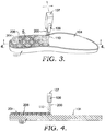
- FIG. 3 depicts an exemplary process that is similar to FIG. 1 where the component 102 for an article of footwear receives a selective laser energy 110 applied thereon to selectively fuse free-flowing powder 200, which may also be referred to as adhesive particulate 200, in accordance with aspects hereof.
- the laser 109 is in coordinated motion with the deposition member 107 such that the application of adhesive particulate and selective application of laser energy are a near contemporaneous process, as an alternative option.
- the laser energy 110 is effective to fuse the adhesive particulate 200 to the component 102 such that a physical bond and/or chemical bonds are formed there between. This process ensures that an adhesive for bonding two or more components together is applied in a proper location and in an optimized geometric structure.
- the fused adhesive particulate may subsequently be heated or otherwise activated to again raise the adhesive particulate to at least a melting temperature such that the component onto which the adhesive particulate is fused is functionally bonded with a second component as the adhesive particulate solidifies in contact with the first and second components.
- FIG. 4 depicts a cross-sectional view along line 4-4 of FIG. 3 .
- laser energy 110 from the laser 109 selectively fuses the adhesive particulate together and to the component 102 resulting in a desired geometric structure of fused adhesive particulate, such as the fused region 206. Because the laser energy is selectively applied, portions of the adhesive particulate remain unfused for subsequent removal from the surface 104, such as unfused region 204.
- FIG. 5 depicts a focused view as identified in FIG. 3 as focus region 5.
- the fused region 206 represents a hatch-like geometric structure that is effective to at least partially surround the unfused region 204. Because the selective application of laser allows some portions of the adhesive particulate to remain unfused while fusing other regions, the unfused portions may be recycled for later application to a component. Also, because the application of the adhesive particulate may be performed with the addition of agents or other chemicals to provide a temporary bond prior to fusing, those additional agents and/or chemicals do not affect the recyclability of the unfused adhesive particulate.
- FIG. 6 depicts a cross-sectional view along line 6-6 of FIG. 5 .
- the unfused portions of the adhesive particulate have been removed to expose the fused regions 206.
- the adhesive particulate is fused to the component 102 such that it forms a coupled geometric structure on the surface 104.
- the geometric structure of fused adhesive particulate may extend above the surface 104 a defined height, such as 1-3 mm. Further, the width or other geometric configuration may be adjusted to provide varied levels of adhesive particulate to achieve a desired level of bonding between components.
- the fused adhesive particulate on a first component is used for the subsequent bonding of that component with another component, such as a shoe upper. Therefore, the selective application of laser energy allows for the resulting selective positioning of adhesive particulate for eventual use in bonding two or more components.
- the adhesive particulate has been discussed as a thermoform type material that can pass through multiple state changes (e.g., solid to liquid to solid to liquid), it may be desired in some aspects to add an agent (e.g., crosslinking agent) to result in a thermoset material (e.g., a reactive hot-melt adhesive).
- a crosslinking agent is to be introduced to a thermoplastic material, the crosslinking agent is introduced after forming the adhesive particulate geometric structure.
- An example of a crosslinking agent may include an encapsulated isophorone diisocyanate (“IPDI”) trimer.
- a crosslinking agent may be applied as a water-based dispersion that is dried on the fused adhesive particulate at a temperature that is below an activation temperature of the agent. Therefore, once the fused adhesive particulate having been treated with the crosslinking agent is heated above the activation temperature and the melting temperature, crosslinking may commence and heat resistance will be affected to the bonding margins between the component(s) and the adhesive particulate. It is further contemplated that a localized surface variation (e.g., increased surface area, porosity, roughness) may be introduced to allow for a more homogeneous distribution of the crosslinking agent (e.g., a hardener) into the fused adhesive particulate.
- the crosslinking agent e.g., a hardener
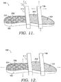
- FIG 11 depicts another aspect of selectively apply laser energy to a substrate, in accordance with aspects hereof.
- a laser source 111 of FIG. 11 is comprised of multiple laser energy emitters that are individually controllable.
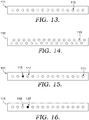
- FIG 13 depicts a substrate-facing surface of the laser source 111 have multiple laser energy emitters 113, in accordance with aspects hereof.
- the laser energy emitters are arranged in a linear fashion; however, it is appreciated that alternative arrangement are contemplated.
- FIG. 14 depicts such an alternative arrangement having a higher density of the laser energy emitters 113 positioned on the laser source 111.
- each of the laser energy emitters is individually controllable, such as by a computing device, to be activated or deactivated at determined locations relative to the substrate.
- FIG. 11 depicts the laser source 112 moving relative to the stationary component 102 (i.e., substrate).
- FIG. 12 depicts the component 102 moving relative to the stationary laser source 111. Irrespective of which element(s) is in motion, as a particular location of the substrate is positioned relative to the laser source, one or more laser source emitters are activated to apply laser energy to selectively fuse adhesive particulate in the beam path of laser energy from the activated emitter(s).
- FIGS. 15 and 16 An exemplary activation of individual laser energy emitters 113 is depicted in FIGS. 15 and 16 .
- a first emitter 115 is activated while a second emitter 117 is deactivated, as depicted in FIG. 15 .
- the activated first emitter 115 emits laser energy effective to increase a temperature of adhesive particulate and/or a substrate.
- the deactivated second emitter 117 abstains from providing laser energy within a beam path of the second emitter 117 such that an substrate and/or adhesive particulate within the potential beam path of the second emitter 117 does not increase beyond a threshold temperature, such as a melting temperature of a particulate (e.g., adhesive particulate) in the beam path. Therefore, laser energy may be selectively applied to a substrate and/or adhesive particulate through the individual control of laser energy emitters, in accordance with aspects hereof.
- a threshold temperature such as a melting temperature of a particulate (e.g., adhesive particulate) in the beam path. Therefore, laser energy may be selectively applied to a substrate and/or adhesive particulate through the individual control of laser energy emitters, in accordance with aspects hereof.
- the first emitter 115 may be deactivated and the second emitter 117 is activated.
- the substrate and/or particulate in a beam path (e.g., area of sufficient energy from a given emitter) of the second emitter 117 is elevated in temperature above the threshold level and the substrate and/or particulate in the beam path of the first emitter 115 remains below the threshold level.
- any number of emitters 113 may be activated and/or deactivated at any time to accomplish a desired selective application of laser energy, as provided herein. Further, it is contemplated that any number of laser energy emitters may be incorporated into the laser source 111, in exemplary aspects.
- the laser source with the multiple independently controllable laser energy emitters may be implemented in other use situations.
- the laser source having multiple independently controllable laser energy emitters could quickly build each layer of the produced part as compared to a traditional energy source.
- any laser energy source may be used as an emitter.
- diode laser emitters and/or carbon dioxide laser emitters may be implemented in connection with the laser source 111.
- a doping element may be introduced and/or used in connection with the particulate and/or substrate to operate in the near infrared (NIR) energy space of the emitters.
- NIR energy space may provide advantages to the laser source 111 with increased life expectancy of components (e.g., the emitters) and lower cost for components (e.g., emitters), in exemplary aspects,.
- FIGS. 7-9 illustrate non-limiting examples for a subsequent activation of the fused adhesive particulate for purposes of bonding the component (e.g., shoe sole) with a second component (e.g., shoe upper).
- a cross-section of one or more components is illustrated in FIGS. 7-9 for discussion and exemplary purposes.
- FIGS. 7 and 8 A first general technique will be illustrated in FIGS. 7 and 8 in which it is contemplated that a flash activation, such as by infrared light, may be used to elevate the fused adhesive particulate to a substantial temperature (e.g., melting temperature). At which point the to-be-bonded components are mated together (e.g., brought together under a sufficient pressure) until the adhesive particulate has recrystallized.
- a second contemplated activation technique which will be illustrated in FIG. 9 hereinafter, contemplates first mating the to-be-bonded components and then heating the fused adhesive particulate to a sufficient temperature after which the pressure is maintained until the temperature can be brought back down below a crystallization temperature of the adhesive particulate.
- a sole component 704 having fused adhesive particulate 708 is depicted being activated prior to being mated with an upper component 702, in accordance with aspects hereof.
- a thermal energy-providing source may be used to increase the temperature of the fused adhesive particulate to a sufficient temperature that the fused adhesive particulate may serve as an adhesive between the sole component 704 and the upper component 702 when mated and maintained with pressure until the fused adhesive particulate recrystallizes.
- the thermal energy source may be any suitable energy source.
- the thermal energy source may be an infrared emitter 710 that emits energy in a frequency sufficient to generate thermal energy at the fused adhesive particulate 708. While a single infrared emitter 710 is depicted, it is understood that any number, combination, type, style, frequency, and the like may be implemented to achieve a thermal energy source suitable for aspects provided herein.
- the sole component 704 and the upper 702 are mated together with forces 712 and/or 711.
- the components may be maintained in a compressed relationship for a sufficient time to allow the fused adhesive particulate to cool and recrystallize forming a bond between the sole component 704 and the upper component 702, in an exemplary aspect. Because the components are brought into contact after activation of the fused adhesive particulate, the fused adhesive particulate may be selected to have a slower recrystallization rate allowing the components to be brought into a mated configuration prior to recrystallizing, in an exemplary aspect.
- the fused adhesive particulate 708 is only provided on one component, the sole component 704.
- the upper component 702 is free of the fused adhesive particulate prior to being placed in a mated configuration. Therefore, the bonding between the sole component 704 and the upper component 702 is dependent, in this example, on the fused adhesive particulate 708 of the sole component 704.
- a bottom surface 703 of the upper component 702 is brought into contact with the sole component 704 allowing for the fused adhesive particulate 708 to bond the components together, in this example.
- the fused adhesive particulate 708 extends up the non-horizontal sidewall 706 of the sole 704. Therefore, unlike planar application of powdered materials, aspects contemplate multi-surface application of the adhesive particulate for fusing.
- the sole component 704 may be bonded with the upper component up to a bite line, an intersection between the sole sidewall top edge and the upper 702. Therefore, a subsequent adhesive application or additional bonding technique may be avoided in the manufacturing of an article of footwear by allowing the fused adhesive particulate to extend across both horizontal and non-horizontal surfaces, in exemplary aspects.
- FIG. 8 depicts a second example of the upper component 702 and the sole component 704 receiving a thermal energy prior to being mated, in accordance with aspects hereof.
- the upper component 702 has applied thereon a fused adhesive particulate layer 705.
- the fused particulate layer 705 may be formed from a similar adhesive particulate as that forming the fused particulate layer 708 applied to the sole component 704. While a single infrared emitter 710 is depicted, it is understood that any number, combination, type, style, frequency, and the like may be implemented to achieve a thermal energy source suitable for aspects provided herein.
- thermal energy sources emitting energy at various angles may be implemented to achieve a relatively homogeneous thermal energy generation across the various adhesive particulate portions. It is contemplated that having the fused adhesive particulate located on both the upper component 702 and the sole component 704 may provide, for some materials forming one or more components, a more consistent and complete bond between the components, for example. However, in some aspects having different materials and/or components, a single application of adhesive particulate may be sufficient to achieve a desired bond.
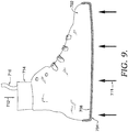
- FIG. 9 depicts an alternative method of activating fused adhesive particulate for bonding the upper component 702 and the sole component 704, in accordance with aspects hereof.
- the components are mated together under pressure (e.g., pressure 711 and 712) prior to re-activating (e.g., taking to a non-crystalline state) the fused adhesive particulate.
- a heat-inducing element such as a thermally variable last 714 may then heat one or more of the components, such as the upper component 702 in this example. The heating of the component then causes the fused adhesive particulate 708 to elevate in temperature sufficiently to bond the components.
- the thermally variable last 714 may be heated using a number of different mechanisms.
- an energy supply member 716 may provide hot liquid or electrical current for peltier devices, internal induction devices, resistive heating devices, polymide heating devices, and the like.
- the heat generated by or in the energy supply member 716 is sufficient to raise a temperature of the adhesive particulate to a melting temperature allowing for the bonding of the components.
- FIG. 10 illustrates a representation of a method 1000 of applying an adhesive particulate to an article of footwear component.
- an adhesive particulate is applied to a component.
- the particulate may be deposited by gravity, pressure, electrostatic adhesion, or any suitable means.
- a conducting agent may not be applied to the component in an exemplary aspect.
- the material from which the component is formed serves as a sufficient ground to achieve a desired degree of electrostatic adhesive for the eventual fusing operation to be performed, in an exemplary aspect.
- primer may be applied to the component to achieve a stronger bond between the adhesive particulate and the component.
- the primer may be an ultraviolet activated primer that produces a sufficient bonding surface onto which the adhesive particulate may be fused, in an exemplary aspect.
- the adhesive particulate may be a dry or liquid material.
- the adhesive particulate is a powdered adhesive, such as TPU, EVA, or a polyolefin material, at least in part.
- the adhesive particulate may also be comprised of a doping agent that allows for varied responses to one or more energy sources.
- an infrared doping agent may be included in the adhesive particulate that aids in the thermal response to an infrared energy source.
- the adhesive particulate may have a melting temperature ranging between 50 and 130 degrees Celsius. It is further contemplated that the melting temperature is in a range of 60 to 90 degrees Celsius, in an exemplary aspect.
- laser energy is selectively applied to the adhesive particulate.
- the adhesive particulate affected by the laser energy is increased in temperature sufficiently to fuse and bond with the underlying component.
- the sufficient temperature is at or above the melting temperature of the adhesive particulate, in an exemplary aspect.
- the fused adhesive particulate forms a geometric structure, a fused region, that is selected to result in an appropriate quantity of the adhesive particulate at a desired location to achieve a desired bonding between two components.
- a band of fused adhesive particulate may extend around an inner sidewall up to near a top edge to securely bond the sole to an upper at the bite line.
- a foot-supporting surface of a sole may have a geometric pattern, such as a bounded structure, that provides consistent or relatively uniform distribution of adhesive particulate without requiring a complete surface covering of the adhesive particulate.
- a precise application of adhesive particulate may be achieved through the selective application of laser energy, such that depending on some component size, style, and shape, a predetermined amount and coverage of fused adhesive particulate is achieved.
- the selective application of laser energy may include applying laser energy in a first location and omitting laser energy in a second location.
- the omission may be accomplished by blocking the laser energy or eliminating power to the laser.
- a fusing of the adhesive particulate may occur, and where the laser is not applied, the adhesive particulate remains as a free-flowing particulate, in an exemplary aspect.
- a frequency, speed, or power level of the laser may be adjusted to alter whether the adhesive particulate achieves a melting temperature (e.g., fuses) or does not melt in a given location.
- unfused adhesive particulate is removed from the component.
- Unfused adhesive particulate is adhesive particulate that was not elevated for a sufficient time to a sufficient temperature to fuse with at least the underlying component.
- the unfused material may be removed by gravity, compressed fluids, vacuum, or other removal techniques.
- the unfused material may be recycled for subsequent operations.
- thermal energy is applied to the fused regions of the adhesive particulate.
- the thermal energy may be provided by an energy emitter, such as an infrared light source, or it may be provided by a conductive member, such as a thermally regulated last, in an exemplary aspect.
- This application of thermal energy elevates a temperature of the fused adhesive particulate sufficiently to achieve a melting temperature state transition that allows the adhesive particulate to serve as a bonding agent between two components.
- a crosslinking agent may be introduced to result in a thermoset material such that a subsequent application of heat is less likely to result in a loss of bond between the two components.
- the temperature may be raised in the range of 60 degrees Celsius and 80 degrees Celsius, in an exemplary aspect.
- the temperature of the adhesive particulate may be raised to a temperature range between 80 degrees Celsius and 110 degrees Celsius, in yet another exemplary aspect.
- the use of a crosslinking agent may depend on the characteristics of the substrate onto which the adhesive particulate is fused. For example, if physical characteristics or chemical characteristics of the substrate are affected by the higher temperature range used in an exemplary heating of a non-crosslinking added adhesive particulate, the lower temperature range of the cross linking laced adhesive particulate may be implemented, for example.
- a block 1010 represents an optional step of recycling the unfused portion of the adhesive particulate for a subsequent application to another article of footwear component.
- the adhesive particulate is useable in a subsequent operation as it is a thermoform material that may be brought to a melting temperature to fuse or bond with one or more components. While specific examples in FIG. 10 are directed to articles of footwear, it is contemplated that the method steps are applicable to other fields, articles, and industries, as provided herein and discussed hereinafter.
Landscapes
- Chemical & Material Sciences (AREA)
- Organic Chemistry (AREA)
- Engineering & Computer Science (AREA)
- Mechanical Engineering (AREA)
- Materials Engineering (AREA)
- Life Sciences & Earth Sciences (AREA)
- Wood Science & Technology (AREA)
- Adhesives Or Adhesive Processes (AREA)
- Footwear And Its Accessory, Manufacturing Method And Apparatuses (AREA)
- Lining Or Joining Of Plastics Or The Like (AREA)
Claims (15)
- Procédé d'application d'une matière particulaire adhésive sur un substrat non métallique, le procédé comprenant: l'application d'une matière particulaire adhésive sur une partie du substrat; l'application sélective d'énergie laser depuis une source laser présentant de multiples émetteurs d'énergie laser indépendamment contrôlables et sélectivement activés, l'application sélective d'énergie laser est appliquée à la matière particulaire adhésive et au substrat pour fusionner sélectivement la matière particulaire adhésive et le substrat, formant une partie fusionnée de matière particulaire adhésive; et après l'application sélective de l'énergie laser, élimination du substrat d'une partie non fusionnée de la matière particulaire adhésive appliquée.
- Procédé selon la revendication 1, comprenant en outre: après l'élimination de la partie non fusionnée de la matière particulaire adhésive appliquée, l'application d'énergie thermique à la matière particulaire adhésive fusionnée pour coller le substrat à un deuxième substrat.
- Procédé selon la revendication 1, dans lequel l'application de la matière particulaire adhésive utilise un applicateur électrostatique qui charge d'électricité statique la matière particulaire adhésive, dans lequel de préférence un agent conducteur n'est pas appliqué au substrat pour réaliser l'application électrostatique de la matière particulaire adhésive.
- Procédé selon la revendication 1, dans lequel la matière particulaire adhésive est constituée d'un adhésif pulvérulent, dans lequel l'adhésif pulvérulent est de préférence constitué d'au moins l'un sélectionné parmi les suivants: un polyuréthane thermoplastique ("TPU"), l'éthylène acétate de vinyle ("EVA"); et des polyoléfines.
- Procédé selon la revendication 1, dans lequel la matière particulaire adhésive comprend un agent de dopage infrarouge.
- Procédé selon la revendication 1, dans lequel l'application sélective de l'énergie laser comprend soit l'application de l'énergie laser sur une première partie de la matière particulaire adhésive dans un emplacement par rapport au substrat où l'on souhaite l'adhésif et la non-application de l'énergie laser sur une deuxième partie de la matière particulaire adhésive dans un emplacement par rapport au substrat où l'on ne souhaite pas l'adhésif; ou
la variation du niveau d'énergie appliquée depuis un laser sur un premier emplacement du substrat par rapport à un deuxième emplacement du substrat. - Procédé selon la revendication 1, dans lequel l'application sélective d'énergie laser produit un périmètre de matière particulaire adhésive fusionnée enfermant une surface de matière particulaire adhésive non fusionnée.
- Procédé selon la revendication 2, dans lequel après l'élimination de la matière particulaire adhésive non fusionnée, on a l'application d'une matière de réticulation à la matière particulaire adhésive fusionnée,
dans lequel la matière de réticulation est de préférence un durcissant d'isocyanate encapsulé. - Procédé selon la revendication 2, dans lequel l'application d'énergie thermique est, au moins en partie: produite d'une source d'énergie infrarouge; ou conduite à travers le substrat à la matière particulaire adhésive fusionnée.
- Procédé selon la revendication 2, dans lequel l'application d'énergie thermique élève la matière particulaire adhésive fusionnée à une plage de températures située entre 80 degrés Celsius et 110 degrés Celsius.
- Procédé selon la revendication 2, dans lequel après l'application d'énergie thermique à la matière particulaire adhésive fusionnée, on a le collage du composant de l'article de chausseur au deuxième substrat, dans lequel le deuxième substrat est de préférence constitué d'une partie de matière particulaire adhésive fusionnée.
- Procédé selon la revendication 1, dans lequel la source laser ayant de multiples émetteurs d'énergie laser sélectivement activés est constituée de: un premier émetteur laser activé sur un premier emplacement par rapport au substrat et un deuxième émetteur laser désactivé sur le premier emplacement; et le premier émetteur laser désactivé à un deuxième emplacement par rapport au substrat et le deuxième émetteur laser activé au deuxième emplacement.
- Procédé selon la revendication 1, dans lequel chacun des multiples émetteurs d'énergie laser est sélectivement activé et désactivé sur base de leur emplacement relatif au substrat.
- Procédé selon la revendication 1 comprenant en outre le déplacement du substrat par rapport à la source laser, dans lequel la source laser a une position statique pendant que le substrat se déplace.
- Procédé selon la revendication 1 comprenant en outre le déplacement de la source laser par rapport au substrat, dans lequel le substrat a une position statique pendant que la source laser se déplace.
Applications Claiming Priority (2)
| Application Number | Priority Date | Filing Date | Title |
|---|---|---|---|
| US14/717,674 US9707727B2 (en) | 2014-04-09 | 2015-05-20 | Selectively applied adhesive particulate on nonmetallic substrates |
| PCT/US2016/030656 WO2016186837A1 (fr) | 2015-05-20 | 2016-05-04 | Matière particulaire adhésive appliquée sélectivement sur des substrats non métalliques |
Publications (2)
| Publication Number | Publication Date |
|---|---|
| EP3298095A1 EP3298095A1 (fr) | 2018-03-28 |
| EP3298095B1 true EP3298095B1 (fr) | 2020-05-27 |
Family
ID=56027200
Family Applications (1)
| Application Number | Title | Priority Date | Filing Date |
|---|---|---|---|
| EP16724196.7A Active EP3298095B1 (fr) | 2015-05-20 | 2016-05-04 | Matière particulaire adhésive appliquée sélectivement sur des substrats non métalliques |
Country Status (5)
| Country | Link |
|---|---|
| EP (1) | EP3298095B1 (fr) |
| KR (1) | KR102037491B1 (fr) |
| CN (1) | CN107922791B (fr) |
| MX (1) | MX2017014614A (fr) |
| WO (1) | WO2016186837A1 (fr) |
Families Citing this family (6)
| Publication number | Priority date | Publication date | Assignee | Title |
|---|---|---|---|---|
| TWI761525B (zh) | 2017-06-01 | 2022-04-21 | 荷蘭商耐克創新有限合夥公司 | 使用發泡粒子製備物件的方法 |
| WO2019157805A1 (fr) * | 2018-02-13 | 2019-08-22 | 陈志勇 | Matériau de semelle intermédiaire et son procédé de fabrication, matériau de semelle d'usure, film adhésif thermofusible, appareil de stratification et semelle |
| CN115956737B (zh) | 2018-12-06 | 2025-12-02 | 耐克创新有限合伙公司 | 利用泡沫颗粒制造物品的方法 |
| CN113727621A (zh) | 2019-02-19 | 2021-11-30 | 奇妙未来风险投资有限公司 | 用于制造鞋类和鞋类部件的方法 |
| CN114945458A (zh) | 2019-11-19 | 2022-08-26 | 耐克创新有限合伙公司 | 制造具有泡沫颗粒的物品的方法 |
| IT202200014512A1 (it) * | 2022-09-16 | 2024-03-16 | Casarotti Calzature S R L | Sistema per produrre calzature artigianali con metodo industriale |
Family Cites Families (18)
| Publication number | Priority date | Publication date | Assignee | Title |
|---|---|---|---|---|
| DE2735497A1 (de) * | 1977-08-06 | 1979-02-15 | Veba Chemie Ag | Pulverfoermige polyurethanlacke |
| DE4434917C1 (de) * | 1994-09-29 | 1996-02-22 | Siemens Ag | Verfahren zum selektiven Aufbringen von Klebstoff |
| CN1222466C (zh) * | 2000-06-20 | 2005-10-12 | 财团法人川村理化学研究所 | 具有叠层结构的微型装置及其制造方法 |
| DE10050231A1 (de) * | 2000-10-11 | 2002-04-25 | Degussa | Vernetzende Basisschicht für Fixiereinlagen nach dem Doppelpunkt- und Pastenverfahren |
| US6509128B1 (en) * | 2000-10-25 | 2003-01-21 | 3M Innovative Properties Company | Imagewise printing of adhesives and limited coalescence polymerization method |
| WO2002034853A1 (fr) * | 2000-10-25 | 2002-05-02 | 3M Innovative Properties Company | Adhesifs latents rendus tres collants, et leurs procedes d'utilisation |
| JP2002178559A (ja) * | 2000-12-14 | 2002-06-26 | Asahi Optical Co Ltd | レーザ走査装置の出力制御回路 |
| GB0102228D0 (en) * | 2001-01-29 | 2001-03-14 | Gluco Ltd | Adhesive |
| US6936644B2 (en) * | 2002-10-16 | 2005-08-30 | Cookson Electronics, Inc. | Releasable microcapsule and adhesive curing system using the same |
| US20040265504A1 (en) * | 2003-06-27 | 2004-12-30 | Christophe Magnin | Non-metalic substrate having an electostatically applied activatable powder adhesive |
| DE102006021171A1 (de) * | 2006-05-06 | 2007-11-08 | W. Döllken & Co. GmbH | Deckleiste |
| KR101004339B1 (ko) * | 2006-12-01 | 2010-12-28 | 디아이씨 가부시끼가이샤 | 습기 경화성 폴리우레탄 핫멜트 접착제 및 이것을 사용한 적층 시트 |
| CN101284265B (zh) * | 2007-04-13 | 2010-09-08 | 欧利速精密工业股份有限公司 | 热熔黏胶粉末用于非金属物体表面的处理方法及处理装置 |
| US9572402B2 (en) * | 2007-10-23 | 2017-02-21 | Nike, Inc. | Articles and methods of manufacturing articles |
| DE102010041521A1 (de) * | 2010-09-28 | 2012-03-29 | Klebchemie M.G. Becker Gmbh & Co. Kg | Reaktivierbare Schmelzklebstoffzusammensetzung und Verwendung derselben |
| US9320312B2 (en) * | 2012-08-30 | 2016-04-26 | Nike, Inc. | Composite upper for shoe with selectively disposed bonding agent |
| US9707727B2 (en) * | 2014-04-09 | 2017-07-18 | Nike, Inc. | Selectively applied adhesive particulate on nonmetallic substrates |
| US10004292B2 (en) * | 2014-04-09 | 2018-06-26 | Nike, Inc. | Selectively applied adhesive particulate on nonmetallic substrates |
-
2016
- 2016-05-04 CN CN201680043437.0A patent/CN107922791B/zh active Active
- 2016-05-04 MX MX2017014614A patent/MX2017014614A/es unknown
- 2016-05-04 KR KR1020177036629A patent/KR102037491B1/ko active Active
- 2016-05-04 EP EP16724196.7A patent/EP3298095B1/fr active Active
- 2016-05-04 WO PCT/US2016/030656 patent/WO2016186837A1/fr not_active Ceased
Non-Patent Citations (1)
| Title |
|---|
| None * |
Also Published As
| Publication number | Publication date |
|---|---|
| KR20180011187A (ko) | 2018-01-31 |
| KR102037491B1 (ko) | 2019-10-29 |
| CN107922791A (zh) | 2018-04-17 |
| MX2017014614A (es) | 2018-03-01 |
| CN107922791B (zh) | 2021-03-16 |
| EP3298095A1 (fr) | 2018-03-28 |
| WO2016186837A1 (fr) | 2016-11-24 |
Similar Documents
| Publication | Publication Date | Title |
|---|---|---|
| US10702011B2 (en) | Selectively applied adhesive particulate on nonmetallic substrates | |
| US9707727B2 (en) | Selectively applied adhesive particulate on nonmetallic substrates | |
| EP3298095B1 (fr) | Matière particulaire adhésive appliquée sélectivement sur des substrats non métalliques | |
| US20250000202A1 (en) | Method and device for the manufacture of sporting goods and sporting goods manufactured thereby | |
| CN104411199B (zh) | 用于鞋类制造的感应加热装置和工艺 | |
| US10835000B2 (en) | Cutting assembly for manufacturing footwear having sipes | |
| JP2022183212A (ja) | プラスチック構成要素を製造するための方法 | |
| TWI637795B (zh) | 以電漿清潔彈性組件的方法及電漿清潔系統 | |
| JP7130060B2 (ja) | シューアッパーの製造方法 | |
| US11691351B2 (en) | High frequency adhesive bonding | |
| KR20260054723A (ko) | 혼합 접착제 |
Legal Events
| Date | Code | Title | Description |
|---|---|---|---|
| STAA | Information on the status of an ep patent application or granted ep patent |
Free format text: STATUS: THE INTERNATIONAL PUBLICATION HAS BEEN MADE |
|
| PUAI | Public reference made under article 153(3) epc to a published international application that has entered the european phase |
Free format text: ORIGINAL CODE: 0009012 |
|
| STAA | Information on the status of an ep patent application or granted ep patent |
Free format text: STATUS: REQUEST FOR EXAMINATION WAS MADE |
|
| 17P | Request for examination filed |
Effective date: 20171218 |
|
| AK | Designated contracting states |
Kind code of ref document: A1 Designated state(s): AL AT BE BG CH CY CZ DE DK EE ES FI FR GB GR HR HU IE IS IT LI LT LU LV MC MK MT NL NO PL PT RO RS SE SI SK SM TR |
|
| AX | Request for extension of the european patent |
Extension state: BA ME |
|
| DAV | Request for validation of the european patent (deleted) | ||
| DAX | Request for extension of the european patent (deleted) | ||
| RIC1 | Information provided on ipc code assigned before grant |
Ipc: A43D 25/20 20060101ALI20191210BHEP Ipc: B32B 5/14 20060101ALI20191210BHEP Ipc: B29D 35/12 20100101ALI20191210BHEP Ipc: B32B 25/04 20060101ALI20191210BHEP Ipc: B32B 7/12 20060101ALI20191210BHEP Ipc: C09J 5/06 20060101AFI20191210BHEP Ipc: A43B 13/04 20060101ALI20191210BHEP Ipc: B32B 5/18 20060101ALI20191210BHEP Ipc: B32B 5/16 20060101ALI20191210BHEP Ipc: B32B 27/40 20060101ALI20191210BHEP Ipc: B29D 35/10 20100101ALI20191210BHEP Ipc: A43B 9/12 20060101ALI20191210BHEP |
|
| GRAP | Despatch of communication of intention to grant a patent |
Free format text: ORIGINAL CODE: EPIDOSNIGR1 |
|
| STAA | Information on the status of an ep patent application or granted ep patent |
Free format text: STATUS: GRANT OF PATENT IS INTENDED |
|
| INTG | Intention to grant announced |
Effective date: 20200127 |
|
| RAP1 | Party data changed (applicant data changed or rights of an application transferred) |
Owner name: NIKE INNOVATE C.V. |
|
| GRAS | Grant fee paid |
Free format text: ORIGINAL CODE: EPIDOSNIGR3 |
|
| GRAA | (expected) grant |
Free format text: ORIGINAL CODE: 0009210 |
|
| STAA | Information on the status of an ep patent application or granted ep patent |
Free format text: STATUS: THE PATENT HAS BEEN GRANTED |
|
| AK | Designated contracting states |
Kind code of ref document: B1 Designated state(s): AL AT BE BG CH CY CZ DE DK EE ES FI FR GB GR HR HU IE IS IT LI LT LU LV MC MK MT NL NO PL PT RO RS SE SI SK SM TR |
|
| REG | Reference to a national code |
Ref country code: GB Ref legal event code: FG4D |
|
| REG | Reference to a national code |
Ref country code: CH Ref legal event code: EP |
|
| REG | Reference to a national code |
Ref country code: AT Ref legal event code: REF Ref document number: 1274533 Country of ref document: AT Kind code of ref document: T Effective date: 20200615 |
|
| REG | Reference to a national code |
Ref country code: DE Ref legal event code: R096 Ref document number: 602016037021 Country of ref document: DE |
|
| REG | Reference to a national code |
Ref country code: LT Ref legal event code: MG4D |
|
| PG25 | Lapsed in a contracting state [announced via postgrant information from national office to epo] |
Ref country code: NO Free format text: LAPSE BECAUSE OF FAILURE TO SUBMIT A TRANSLATION OF THE DESCRIPTION OR TO PAY THE FEE WITHIN THE PRESCRIBED TIME-LIMIT Effective date: 20200827 Ref country code: IS Free format text: LAPSE BECAUSE OF FAILURE TO SUBMIT A TRANSLATION OF THE DESCRIPTION OR TO PAY THE FEE WITHIN THE PRESCRIBED TIME-LIMIT Effective date: 20200927 Ref country code: FI Free format text: LAPSE BECAUSE OF FAILURE TO SUBMIT A TRANSLATION OF THE DESCRIPTION OR TO PAY THE FEE WITHIN THE PRESCRIBED TIME-LIMIT Effective date: 20200527 Ref country code: PT Free format text: LAPSE BECAUSE OF FAILURE TO SUBMIT A TRANSLATION OF THE DESCRIPTION OR TO PAY THE FEE WITHIN THE PRESCRIBED TIME-LIMIT Effective date: 20200928 Ref country code: SE Free format text: LAPSE BECAUSE OF FAILURE TO SUBMIT A TRANSLATION OF THE DESCRIPTION OR TO PAY THE FEE WITHIN THE PRESCRIBED TIME-LIMIT Effective date: 20200527 Ref country code: LT Free format text: LAPSE BECAUSE OF FAILURE TO SUBMIT A TRANSLATION OF THE DESCRIPTION OR TO PAY THE FEE WITHIN THE PRESCRIBED TIME-LIMIT Effective date: 20200527 Ref country code: GR Free format text: LAPSE BECAUSE OF FAILURE TO SUBMIT A TRANSLATION OF THE DESCRIPTION OR TO PAY THE FEE WITHIN THE PRESCRIBED TIME-LIMIT Effective date: 20200828 |
|
| REG | Reference to a national code |
Ref country code: NL Ref legal event code: MP Effective date: 20200527 |
|
| PG25 | Lapsed in a contracting state [announced via postgrant information from national office to epo] |
Ref country code: BG Free format text: LAPSE BECAUSE OF FAILURE TO SUBMIT A TRANSLATION OF THE DESCRIPTION OR TO PAY THE FEE WITHIN THE PRESCRIBED TIME-LIMIT Effective date: 20200827 Ref country code: RS Free format text: LAPSE BECAUSE OF FAILURE TO SUBMIT A TRANSLATION OF THE DESCRIPTION OR TO PAY THE FEE WITHIN THE PRESCRIBED TIME-LIMIT Effective date: 20200527 Ref country code: LV Free format text: LAPSE BECAUSE OF FAILURE TO SUBMIT A TRANSLATION OF THE DESCRIPTION OR TO PAY THE FEE WITHIN THE PRESCRIBED TIME-LIMIT Effective date: 20200527 Ref country code: HR Free format text: LAPSE BECAUSE OF FAILURE TO SUBMIT A TRANSLATION OF THE DESCRIPTION OR TO PAY THE FEE WITHIN THE PRESCRIBED TIME-LIMIT Effective date: 20200527 |
|
| REG | Reference to a national code |
Ref country code: AT Ref legal event code: MK05 Ref document number: 1274533 Country of ref document: AT Kind code of ref document: T Effective date: 20200527 |
|
| PG25 | Lapsed in a contracting state [announced via postgrant information from national office to epo] |
Ref country code: AL Free format text: LAPSE BECAUSE OF FAILURE TO SUBMIT A TRANSLATION OF THE DESCRIPTION OR TO PAY THE FEE WITHIN THE PRESCRIBED TIME-LIMIT Effective date: 20200527 Ref country code: NL Free format text: LAPSE BECAUSE OF FAILURE TO SUBMIT A TRANSLATION OF THE DESCRIPTION OR TO PAY THE FEE WITHIN THE PRESCRIBED TIME-LIMIT Effective date: 20200527 |
|
| PG25 | Lapsed in a contracting state [announced via postgrant information from national office to epo] |
Ref country code: DK Free format text: LAPSE BECAUSE OF FAILURE TO SUBMIT A TRANSLATION OF THE DESCRIPTION OR TO PAY THE FEE WITHIN THE PRESCRIBED TIME-LIMIT Effective date: 20200527 Ref country code: ES Free format text: LAPSE BECAUSE OF FAILURE TO SUBMIT A TRANSLATION OF THE DESCRIPTION OR TO PAY THE FEE WITHIN THE PRESCRIBED TIME-LIMIT Effective date: 20200527 Ref country code: EE Free format text: LAPSE BECAUSE OF FAILURE TO SUBMIT A TRANSLATION OF THE DESCRIPTION OR TO PAY THE FEE WITHIN THE PRESCRIBED TIME-LIMIT Effective date: 20200527 Ref country code: AT Free format text: LAPSE BECAUSE OF FAILURE TO SUBMIT A TRANSLATION OF THE DESCRIPTION OR TO PAY THE FEE WITHIN THE PRESCRIBED TIME-LIMIT Effective date: 20200527 Ref country code: SM Free format text: LAPSE BECAUSE OF FAILURE TO SUBMIT A TRANSLATION OF THE DESCRIPTION OR TO PAY THE FEE WITHIN THE PRESCRIBED TIME-LIMIT Effective date: 20200527 Ref country code: IT Free format text: LAPSE BECAUSE OF FAILURE TO SUBMIT A TRANSLATION OF THE DESCRIPTION OR TO PAY THE FEE WITHIN THE PRESCRIBED TIME-LIMIT Effective date: 20200527 Ref country code: RO Free format text: LAPSE BECAUSE OF FAILURE TO SUBMIT A TRANSLATION OF THE DESCRIPTION OR TO PAY THE FEE WITHIN THE PRESCRIBED TIME-LIMIT Effective date: 20200527 Ref country code: CZ Free format text: LAPSE BECAUSE OF FAILURE TO SUBMIT A TRANSLATION OF THE DESCRIPTION OR TO PAY THE FEE WITHIN THE PRESCRIBED TIME-LIMIT Effective date: 20200527 |
|
| PG25 | Lapsed in a contracting state [announced via postgrant information from national office to epo] |
Ref country code: PL Free format text: LAPSE BECAUSE OF FAILURE TO SUBMIT A TRANSLATION OF THE DESCRIPTION OR TO PAY THE FEE WITHIN THE PRESCRIBED TIME-LIMIT Effective date: 20200527 Ref country code: SK Free format text: LAPSE BECAUSE OF FAILURE TO SUBMIT A TRANSLATION OF THE DESCRIPTION OR TO PAY THE FEE WITHIN THE PRESCRIBED TIME-LIMIT Effective date: 20200527 |
|
| REG | Reference to a national code |
Ref country code: DE Ref legal event code: R097 Ref document number: 602016037021 Country of ref document: DE |
|
| PLBE | No opposition filed within time limit |
Free format text: ORIGINAL CODE: 0009261 |
|
| STAA | Information on the status of an ep patent application or granted ep patent |
Free format text: STATUS: NO OPPOSITION FILED WITHIN TIME LIMIT |
|
| 26N | No opposition filed |
Effective date: 20210302 |
|
| PG25 | Lapsed in a contracting state [announced via postgrant information from national office to epo] |
Ref country code: SI Free format text: LAPSE BECAUSE OF FAILURE TO SUBMIT A TRANSLATION OF THE DESCRIPTION OR TO PAY THE FEE WITHIN THE PRESCRIBED TIME-LIMIT Effective date: 20200527 |
|
| REG | Reference to a national code |
Ref country code: CH Ref legal event code: PL |
|
| PG25 | Lapsed in a contracting state [announced via postgrant information from national office to epo] |
Ref country code: CH Free format text: LAPSE BECAUSE OF NON-PAYMENT OF DUE FEES Effective date: 20210531 Ref country code: LU Free format text: LAPSE BECAUSE OF NON-PAYMENT OF DUE FEES Effective date: 20210504 Ref country code: MC Free format text: LAPSE BECAUSE OF FAILURE TO SUBMIT A TRANSLATION OF THE DESCRIPTION OR TO PAY THE FEE WITHIN THE PRESCRIBED TIME-LIMIT Effective date: 20200527 Ref country code: LI Free format text: LAPSE BECAUSE OF NON-PAYMENT OF DUE FEES Effective date: 20210531 |
|
| REG | Reference to a national code |
Ref country code: BE Ref legal event code: MM Effective date: 20210531 |
|
| PG25 | Lapsed in a contracting state [announced via postgrant information from national office to epo] |
Ref country code: IE Free format text: LAPSE BECAUSE OF NON-PAYMENT OF DUE FEES Effective date: 20210504 |
|
| PG25 | Lapsed in a contracting state [announced via postgrant information from national office to epo] |
Ref country code: BE Free format text: LAPSE BECAUSE OF NON-PAYMENT OF DUE FEES Effective date: 20210531 |
|
| PG25 | Lapsed in a contracting state [announced via postgrant information from national office to epo] |
Ref country code: HU Free format text: LAPSE BECAUSE OF FAILURE TO SUBMIT A TRANSLATION OF THE DESCRIPTION OR TO PAY THE FEE WITHIN THE PRESCRIBED TIME-LIMIT; INVALID AB INITIO Effective date: 20160504 |
|
| P01 | Opt-out of the competence of the unified patent court (upc) registered |
Effective date: 20230515 |
|
| PG25 | Lapsed in a contracting state [announced via postgrant information from national office to epo] |
Ref country code: CY Free format text: LAPSE BECAUSE OF FAILURE TO SUBMIT A TRANSLATION OF THE DESCRIPTION OR TO PAY THE FEE WITHIN THE PRESCRIBED TIME-LIMIT Effective date: 20200527 |
|
| PG25 | Lapsed in a contracting state [announced via postgrant information from national office to epo] |
Ref country code: MK Free format text: LAPSE BECAUSE OF FAILURE TO SUBMIT A TRANSLATION OF THE DESCRIPTION OR TO PAY THE FEE WITHIN THE PRESCRIBED TIME-LIMIT Effective date: 20200527 |
|
| PG25 | Lapsed in a contracting state [announced via postgrant information from national office to epo] |
Ref country code: MT Free format text: LAPSE BECAUSE OF FAILURE TO SUBMIT A TRANSLATION OF THE DESCRIPTION OR TO PAY THE FEE WITHIN THE PRESCRIBED TIME-LIMIT Effective date: 20200527 |
|
| PGFP | Annual fee paid to national office [announced via postgrant information from national office to epo] |
Ref country code: DE Payment date: 20250311 Year of fee payment: 10 |
|
| PG25 | Lapsed in a contracting state [announced via postgrant information from national office to epo] |
Ref country code: TR Free format text: LAPSE BECAUSE OF FAILURE TO SUBMIT A TRANSLATION OF THE DESCRIPTION OR TO PAY THE FEE WITHIN THE PRESCRIBED TIME-LIMIT Effective date: 20200527 |
|
| PGFP | Annual fee paid to national office [announced via postgrant information from national office to epo] |
Ref country code: GB Payment date: 20260316 Year of fee payment: 11 |
|
| PGFP | Annual fee paid to national office [announced via postgrant information from national office to epo] |
Ref country code: FR Payment date: 20260309 Year of fee payment: 11 |