EP3298230B1 - Verfahren und vorrichtung zum schrumpfen von rohrabschnitten - Google Patents
Verfahren und vorrichtung zum schrumpfen von rohrabschnitten Download PDFInfo
- Publication number
- EP3298230B1 EP3298230B1 EP16796818.9A EP16796818A EP3298230B1 EP 3298230 B1 EP3298230 B1 EP 3298230B1 EP 16796818 A EP16796818 A EP 16796818A EP 3298230 B1 EP3298230 B1 EP 3298230B1
- Authority
- EP
- European Patent Office
- Prior art keywords
- tubular
- shrinkage
- die
- forming die
- tool
- Prior art date
- Legal status (The legal status is an assumption and is not a legal conclusion. Google has not performed a legal analysis and makes no representation as to the accuracy of the status listed.)
- Active
Links
Images



Classifications
-
- E—FIXED CONSTRUCTIONS
- E21—EARTH OR ROCK DRILLING; MINING
- E21B—EARTH OR ROCK DRILLING; OBTAINING OIL, GAS, WATER, SOLUBLE OR MELTABLE MATERIALS OR A SLURRY OF MINERALS FROM WELLS
- E21B43/00—Methods or apparatus for obtaining oil, gas, water, soluble or meltable materials or a slurry of minerals from wells
- E21B43/02—Subsoil filtering
- E21B43/10—Setting of casings, screens, liners or the like in wells
-
- E—FIXED CONSTRUCTIONS
- E21—EARTH OR ROCK DRILLING; MINING
- E21B—EARTH OR ROCK DRILLING; OBTAINING OIL, GAS, WATER, SOLUBLE OR MELTABLE MATERIALS OR A SLURRY OF MINERALS FROM WELLS
- E21B31/00—Fishing for or freeing objects in boreholes or wells
- E21B31/12—Grappling tools, e.g. tongs or grabs
- E21B31/16—Grappling tools, e.g. tongs or grabs combined with cutting or destroying means
-
- B—PERFORMING OPERATIONS; TRANSPORTING
- B21—MECHANICAL METAL-WORKING WITHOUT ESSENTIALLY REMOVING MATERIAL; PUNCHING METAL
- B21C—MANUFACTURE OF METAL SHEETS, WIRE, RODS, TUBES, PROFILES OR LIKE SEMI-MANUFACTURED PRODUCTS OTHERWISE THAN BY ROLLING; AUXILIARY OPERATIONS USED IN CONNECTION WITH METAL-WORKING WITHOUT ESSENTIALLY REMOVING MATERIAL
- B21C25/00—Profiling tools for metal extruding
- B21C25/02—Dies
-
- E—FIXED CONSTRUCTIONS
- E21—EARTH OR ROCK DRILLING; MINING
- E21B—EARTH OR ROCK DRILLING; OBTAINING OIL, GAS, WATER, SOLUBLE OR MELTABLE MATERIALS OR A SLURRY OF MINERALS FROM WELLS
- E21B29/00—Cutting or destroying pipes, packers, plugs or wire lines, located in boreholes or wells, e.g. cutting of damaged pipes, of windows; Deforming of pipes in boreholes or wells; Reconditioning of well casings while in the ground
- E21B29/002—Cutting, e.g. milling, a pipe with a cutter rotating along the circumference of the pipe
-
- E—FIXED CONSTRUCTIONS
- E21—EARTH OR ROCK DRILLING; MINING
- E21B—EARTH OR ROCK DRILLING; OBTAINING OIL, GAS, WATER, SOLUBLE OR MELTABLE MATERIALS OR A SLURRY OF MINERALS FROM WELLS
- E21B29/00—Cutting or destroying pipes, packers, plugs or wire lines, located in boreholes or wells, e.g. cutting of damaged pipes, of windows; Deforming of pipes in boreholes or wells; Reconditioning of well casings while in the ground
- E21B29/002—Cutting, e.g. milling, a pipe with a cutter rotating along the circumference of the pipe
- E21B29/007—Cutting, e.g. milling, a pipe with a cutter rotating along the circumference of the pipe with a radially-retracting cutter rotating outside the pipe
-
- E—FIXED CONSTRUCTIONS
- E21—EARTH OR ROCK DRILLING; MINING
- E21B—EARTH OR ROCK DRILLING; OBTAINING OIL, GAS, WATER, SOLUBLE OR MELTABLE MATERIALS OR A SLURRY OF MINERALS FROM WELLS
- E21B31/00—Fishing for or freeing objects in boreholes or wells
- E21B31/002—Destroying the objects to be fished, e.g. by explosive means
-
- E—FIXED CONSTRUCTIONS
- E21—EARTH OR ROCK DRILLING; MINING
- E21B—EARTH OR ROCK DRILLING; OBTAINING OIL, GAS, WATER, SOLUBLE OR MELTABLE MATERIALS OR A SLURRY OF MINERALS FROM WELLS
- E21B43/00—Methods or apparatus for obtaining oil, gas, water, soluble or meltable materials or a slurry of minerals from wells
- E21B43/02—Subsoil filtering
- E21B43/10—Setting of casings, screens, liners or the like in wells
- E21B43/103—Setting of casings, screens, liners or the like in wells of expandable casings, screens, liners, or the like
Definitions
- the invention relates to a complete system for reducing diameter of tubular pipes more precisely it relates to a drill string system for plug and abandoning of wells, the present invention relates to devices and methods of such a system.
- the invention relates to a complete system for reducing diameter of tubular pipes.
- WO 2008118697 discloses a system of common use for recovering casing from the abandoned wells.
- the present invention enables casing section removal with milling only parts of a tubular/casing.
- a shrinkage tool assembly for shrinkage and recovery of a wellbore tubular according to claim 1, a shrinkage forming die according to claim 6 and a method for shrinkage and recovery of a wellbore tubular according to claim 8.
- the forming die may consist of at least one mechanical mean for guiding the tubular into the die, where the mechanical mean will be activated by mean of an actuating system.
- the recovered tubular section may have at least one helical or straight groove along the longitudinal axis of the tubular.
- a shrinking tool which may utilize the method s indicated above and where the shrinking tool is adjacent to a milling tool, where the milling tool is adapted to mill at least one radial groove and at least one axial or helical groove along the longitudinal axis of the tubular.
- the shrinking tool may be pulled by mean of a moving tractor or other means like as wireline or drillstring from inside the tubular.
- the tool comprises at least one anchoring mean for pulling one section of the tubular, where the separated section consist of at least on helical or axial groove along the longitudinal axis of the tubular.
- the invention relates to a system 1, i.e. a shrinkage tool assembly for shrinkage and recovery of a wellbore tubular, for abandoning and plugging of oil wells as well as a system made for shrinking sections of tubular.
- the system comprises a forming die 15, which can be used in oil, gas and deep-water wells, mining and underground operations.
- the tools enable to shrink a section of a tubular 91 and reduce the diameter.
- a forming tool integrated in a shrinkage tool assembly 1 for shrinkage and recovery of a wellbore tubular comprises the mentioned forming die 15, a milling section 13 including means for milling out helical or axial grooves in tubulars 92 and at least a tractor 10 or pulling means 10.
- the forming die 15 can be used to shrink a casing while the shrinkage tool assembly 1 for shrinkage and recovery of a wellbore tubular moves axially inside the tubular. This enables to pull out and recover a section of the tubular/casing through the rest of the tubular/casing that remains in the well. In addition, the forming die 15 reduces the de-bonding force for the tubular from the cement/formation.
- shrinkage tool assembly 1 for shrinkage and recovery of a wellbore tubular except if nothing else is explicitly mentioned.
- the present invention relates to a system, which is adapted to take out sections of casings or sections of pipes.
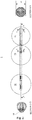
- the system 1 will now be described with reference to figure 1 .
- the system 1 which is the shrinkage tool assembly 1 for shrinkage and recovery of a wellbore tubular comprises a tractor 10, a milling section 13 and a forming die section 15.
- the tractor 15 is the front end of the system with reference to the active travel direction that is, when the system 1 is actively milling and shrinking tubulars or casings. Following the tractor is the milling section 13, the milling section includes at least one cutting tool 14.
- the forming die 15 is adapted to shrink casings or tubulars, which already has been prepared by the milling, section 13 so that the tubulars or casing has premade axial or helical grooves.
- the tractor 10 is the propulsion unit of the drill string, it is shown in detail in figure 4 .
- the tractor comprises two pistons 42, 43 connected with a push pull piston rod 12 there between.
- the push pull piston rod can move the end piston 42 relative to the near piston 43 and the rest of the shrinkage tool assembly (1) for shrinkage and recovery of a wellbore tubular in an axial direction.
- the near piston 43 retracts its anchor pads 11 and the end piston 42 can pull the near piston 43 with its drillstring in the x-direction thereby causing the whole drillstring including the milling section and the die form 15 to move in the x-direction.
- the milling section 13 follows the tractor and is in between the forming die 15 and the tractor 10.
- the milling section shall provide axial grooves in piping-sections or casing sections.
- the groove shall be axial the shrinkage tool assembly 1 for shrinkage and recovery of a wellbore tubular will not rotate around its axis A - A ( fig 2 ).
- the tractor 10 provides movement of the shrinkage tool assembly 1 for shrinkage and recovery of a wellbore tubular the milling section provides axial grooves.
- One or more side cutters 14 are integrated in the milling section 13. The one or more side cutters rotate around its axis of rotation, where the axis of rotation is substantially normal to the axis A-A and the surrounding walls.
- the cutter 14 or cutters 14 can be retractable and expandable. In its expandable positon with one or more rotating cutters, an axial groove will be made in the casing / surrounding tube.
- the cutter 14 or cutters 14 can be rotated by using hydraulic driven/mud motor system placed inside the main housing.
- An internal hydraulic driving system can be placed, axial to the side cutters or axial to the direction of the milling tool and to rotate the side cutters 14 by using a gear/transmission system or by direct drive.
- the driving means can be electric motors with gear transmission drive or by direct drive.
- FIGS. 5c shows an example of use of internal mud motor(s) including a proper gear transmission system 67 for driving the side cutters 14. Any suitable gear type can be utilised. Different gear types such as worm or bevel can be used depending on the tool design. In addition, high torque hydro-motors can also be employed without gear system, the same applies to electric motors.
- Each side cutter has individual driving system and can be operated independent of the other side cutters.
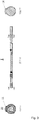
- a shrinkage tool assembly 1 for shrinkage and recovery of a wellbore tubular is shown in figure 1 , 2 and 3 .
- the figures 6 - 10 shows a forming die 15 in detail.
- the forming die has a c-shape entrance opening ( fig. 7a, 7b ) which has similar diameter D1 as a grooved tubular 72 in an entrance end and a smaller diameter DB at the exit end.
- the shrinkage tool assembly 1 for shrinkage and recovery of a wellbore tubular moves axially within the grooved wellbore tubular, the tubular is pushed into the C shaped die entrance opening 83 and inside the C-outer sleeve 75 of the forming die 15.
- the forming die consists of a mechanical means 16 for guiding the grooved tubular 72 or grooved casing into the opening entrance of the die.
- This mechanical means is an expandable guiding arm 16, which radially expands out of the tool body 15 when needed.
- the forming die 15 and the milling tool 13 are adapted to be pulled by a moving tractor 10 or any other means through the wellbore longitude axis.
- Another mean for pulling the die 15 can be by wire, cable or drillstring.
- the milling tool 13 with actively driven side rotational cutters 14 can drill hole and mill axial, helical or radial grooves inside the tubular sidewalls.
- this system 1 includes components, which together facilitates abandonment and plugging of oil wells and dismantling in sewerage systems.
- the milling tool 13 can create at least one helical groove and at least two radial grooves inside the casing downhole in the well.
- a rotational milling tool with one or more rotational side cutters 14. This enables to create a separated casing section from the tubular.
- the separated casing section with at least one helical groove can be pulled in an axial direction, which causes casing shrinkage and de-bonding from the formation cement.
- the separated casing can then be pulled out through the remaining casing inside the well.
- the moving tractor or other means for example the drillstring or wire line, can pull the separated casing section.
Landscapes
- Life Sciences & Earth Sciences (AREA)
- Engineering & Computer Science (AREA)
- Geology (AREA)
- Mining & Mineral Resources (AREA)
- Environmental & Geological Engineering (AREA)
- Fluid Mechanics (AREA)
- Physics & Mathematics (AREA)
- General Life Sciences & Earth Sciences (AREA)
- Geochemistry & Mineralogy (AREA)
- Marine Sciences & Fisheries (AREA)
- Mechanical Engineering (AREA)
- Earth Drilling (AREA)
- Processing And Handling Of Plastics And Other Materials For Molding In General (AREA)
Claims (10)
- Schrumpfwerkzeuganordnung (1) zum Schrumpfen und Rückverformen eines Bohrlochförderrohrs, wobei die Schrumpfwerkzeuganordnung (1) mindestens umfasst:a. ein Umformwerkzeug (15), das entlang der Achse des Bohrlochförderrohrs angeordnet ist, wobei das Umformwerkzeug (15) zum Schrumpfen von Futterrohren oder Förderrohren ausgelegt ist, die bereits mit einem Fräswerkzeug (13) vorbereitet wurden, so dass die Bohrlochförderrohre vorgefertigte axiale oder spiralförmige Nuten aufweisen,b. ein Zugmittel (10) zum Ziehen der Schrumpfwerkzeuganordnung (1) undc. ein aktives Fräswerkzeug (13), wobei das Fräswerkzeug (13) einen oder mehrere aktiv angetriebene seitliche Rotationsschneider (14) umfasst, die Löcher bohren und axiale, spiralförmige oder radiale Nuten innerhalb der Förderrohrseitenwand fräsen können, wobei das Umformwerkzeug konfiguriert ist, um von dem Zugmittel aus dem Inneren des Förderrohrs gezogen zu werden, und wobei das Umformwerkzeug aus einem C-förmigen hochgezogenen Schnitt im Inneren des Werkzeugkörpers mit einem größeren Profildurchmesser am Einlass und einem kleineren Profildurchmesser am Auslass besteht.
- Schrumpfwerkzeuganordnung (1) nach Anspruch 1, wobei das Umformwerkzeug (15) aus mindestens einem mechanischen Mittel (16) zum Führen des Förderrohrs in das Umformwerkzeug besteht, wobei das mechanische Mittel konfiguriert ist, um mittels eines Betätigungssystems aktiviert zu werden.
- Schrumpfwerkzeuganordnung (1) nach Anspruch 1, wobei ein rückverformter Förderrohrabschnitt mindestens eine spiralförmige oder gerade Nut entlang der Längsachse des Förderrohrs aufweisen kann, die durch das aktive Fräswerkzeug (13) hergestellt wurde.
- Schrumpfwerkzeuganordnung (1) nach Anspruch 1, 2 und 3, wobei das Fräswerkzeug ausgelegt ist, um mindestens eine radiale Nut und mindestens eine axiale oder spiralförmige Nut entlang der Längsachse des Förderrohrs zu fräsen.
- Schrumpfwerkzeuganordnung nach Anspruch 1, wobei das Werkzeug (1) mindestens ein Verankerungsmittel zum Ziehen eines Abschnitts des Förderrohrs umfasst, wobei der getrennte Abschnitt aus mindestens einer spiralförmigen oder axialen Nut entlang der Längsachse des Förderrohrs besteht.
- Schrumpfumformwerkzeug (15), umfassend:ein Werkzeugeinlassende (61), einen sich verjüngenden zylindrischen Umformwerkzeugkörper (63) mit einem ersten Ende neben dem Werkzeugeinlassende (61), wobei das erste Ende neben dem Werkzeugeinlassende (61) den breitesten Durchmesser aufweist und der sich verjüngende zylindrische Umformwerkzeugkörper (63) ein zweites Ende gegenüber dem ersten Ende aufweist;eine C-förmige Eintrittsöffnung (83) mit einem Durchmesser D1 an einem vorderen Ende neben dem zweiten Ende des sich verjüngenden zylindrischen Umformwerkzeugkörpers (63) und einem kleineren Durchmesser D2 an der Werkzeugauslassrückseite (62);einen verlängerten radial ausfahrbaren Führungsarm (16), der am Umfang des Schrumpfumformwerkzeugs (15) angeordnet ist und dessen Längsrichtung in Bezug auf das Schrumpfumformwerkzeug (15) axial ausgerichtet ist und der konfiguriert ist, um Futterohre oder Förderrohre mit einer oder mehreren Nuten zu führen.
- Schrumpfformwerkzeug (15) nach Anspruch 6, wobei der verlängerte radial ausfahrbare Führungsarm (16) ein erstes Element (81) mit einer Breite Z2 und ein zweites Element (82) mit einer Breite Z3 umfasst, wobei Z3 > Z2, das erste Element (81) neben dem Werkzeugeinlassende (61) angeordnet ist und das zweite Element radial außerhalb des ersten Elements (81) und axial näher an der Werkzeugauslassrückseite (62) angeordnet ist.
- Verfahren zum Schrumpfen und Rückverformen eines Bohrlochförderrohrs, umfassend die Schritte:a. Bereitstellen einer Schrumpfwerkzeuganordnung (1), wobei die Schrumpfwerkzeuganordnung umfasst:i. ein Umformwerkzeug (15), das entlang der Achse des Bohrlochförderrohrs angeordnet ist, wobei das Umformwerkzeug (15) zum Schrumpfen von Futterrohren oder Förderrohren ausgelegt ist, die bereits mit einem Fräswerkzeug (13) vorbereitet wurden, so dass die Bohrlochförderrohre vorgefertigte axiale oder spiralförmige Nuten aufweisen,ii. ein Zugmittel (10) zum Ziehen der Schrumpfwerkzeuganordnung (1) undiii. ein aktives Fräswerkzeug (13), wobei das Fräswerkzeug (13) einen oder mehrere aktiv angetriebene seitliche Rotationsschneider (14) umfasst, die Löcher bohren und axiale, spiralförmige oder radiale Nuten innerhalb der Förderrohrseitenwand fräsen können,b. Ziehen des Umformwerkzeugs (15) durch das Zugmittel aus dem Inneren des Förderrohrs, wobei das Umformwerkzeug aus einem C-förmigen hochgezogenen Schnitt im Inneren des Werkzeugkörpers mit einem größeren Profildurchmesser am Einlass und einem kleineren Profildurchmesser am Auslass besteht.
- Verfahren nach Anspruch 8, ferner umfassend die Schritte:c. Eindringen in ein genutetes Förderrohr (72), wobei sich der Werkzeugeinlass (61) innerhalb der Außenwände des genuteten Förderrohrs (72) befindet;d. Weiterziehen des Umformwerkzeugeinlasses (61) weiter in das genutete Förderrohr (72),e. Eindringen eines verlängerten radial ausfahrbaren Führungsarms (16), der am Umfang des Schrumpfumformwerkzeugs (15) angeordnet ist und dessen Längsrichtung in Bezug auf das Schrumpfumformwerkzeug (15) axial ausgerichtet ist, in die Nut des genuteten Förderrohrs (72);f. Gedrücktwerden des genuteten Förderrohrs (72) in den C-förmigen hochgezogenen Schnitt im Inneren des Werkzeugkörpers (15) mit einem größeren Profildurchmesser am Einlass (83) und einem kleineren Profildurchmesser am Auslass (62), undg. Austreten eines ersten Endes des genuteten Förderrohrs (72) aus der Werkzeugauslassrückseite (62) mit einem Durchmesser, der kleiner als sein Durchmesser ist, wenn es in den C-förmigen hochgezogenen Schnitt (83) im Inneren des Werkzeugkörpers (15) eindringt.
- Verfahren nach Anspruch 9, ferner umfassend den Schritt:
Bereitstellen eines ersten Elements (81) mit einer Breite Z2 und eines zweiten Elements (82) mit einer Breite Z3, wobei Z3 > Z2 ist, Anordnen des ersten Elements (81) neben dem Werkzeugeinlassende (61) und Anordnen des zweiten Elements radial außerhalb des ersten Elements (81) und axial näher an der Werkzeugauslassrückseite (62).
Applications Claiming Priority (2)
| Application Number | Priority Date | Filing Date | Title |
|---|---|---|---|
| NO20150624A NO20150624A1 (en) | 2015-05-19 | 2015-05-19 | A shrinking tool for shrinkage and recovery of a wellbore tubular. |
| PCT/NO2016/050097 WO2016186517A1 (en) | 2015-05-19 | 2016-05-19 | A method and apparatus for shrinking tubular sections |
Publications (3)
| Publication Number | Publication Date |
|---|---|
| EP3298230A1 EP3298230A1 (de) | 2018-03-28 |
| EP3298230A4 EP3298230A4 (de) | 2019-06-19 |
| EP3298230B1 true EP3298230B1 (de) | 2020-08-19 |
Family
ID=57320760
Family Applications (1)
| Application Number | Title | Priority Date | Filing Date |
|---|---|---|---|
| EP16796818.9A Active EP3298230B1 (de) | 2015-05-19 | 2016-05-19 | Verfahren und vorrichtung zum schrumpfen von rohrabschnitten |
Country Status (3)
| Country | Link |
|---|---|
| EP (1) | EP3298230B1 (de) |
| NO (1) | NO20150624A1 (de) |
| WO (1) | WO2016186517A1 (de) |
Family Cites Families (11)
| Publication number | Priority date | Publication date | Assignee | Title |
|---|---|---|---|---|
| GB616199A (en) * | 1945-08-30 | 1949-01-18 | British Thomson Houston Co Ltd | Improvements in and relating to heading dies and extrusion dies and method of makingthe same |
| FR2765619B1 (fr) * | 1997-07-01 | 2000-10-06 | Schlumberger Cie Dowell | Procede et dispositif pour la completion de puits pour la production d'hydrocarbures ou analogues |
| EP0952305A1 (de) * | 1998-04-23 | 1999-10-27 | Shell Internationale Researchmaatschappij B.V. | Verformbares Rohr |
| US20080236829A1 (en) * | 2007-03-26 | 2008-10-02 | Lynde Gerald D | Casing profiling and recovery system |
| US9022117B2 (en) * | 2010-03-15 | 2015-05-05 | Weatherford Technology Holdings, Llc | Section mill and method for abandoning a wellbore |
| NO334664B1 (no) * | 2010-08-12 | 2014-05-12 | Sinvent As | Skjæreverktøy integrert i en borestreng |
| NO333912B1 (no) * | 2011-11-15 | 2013-10-21 | Leif Invest As | Apparat og fremgangsmåte for kutting og trekking av fôringsrør |
| BR112015023691B1 (pt) * | 2013-03-15 | 2021-10-26 | Schlumberger Technology B.V. | Ferramenta de corte de fundo de poço, método para operar ferramenta de corte de fundo de poço e conjunto de fundo de poço |
| US9359848B2 (en) * | 2013-06-04 | 2016-06-07 | Halliburton Energy Services, Inc. | Systems and methods for removing a section of casing |
| WO2015042136A1 (en) * | 2013-09-18 | 2015-03-26 | Lockheed Martin Corporation | Friction-stir mandrel and friction-stir extrusion and drawing processes |
| EP2990591A1 (de) * | 2014-08-29 | 2016-03-02 | University Of Stavanger | Verfahren und Werkzeug zur Beseitigung von Verkleidungen in Bohrlöchern |
-
2015
- 2015-05-19 NO NO20150624A patent/NO20150624A1/en not_active Application Discontinuation
-
2016
- 2016-05-19 EP EP16796818.9A patent/EP3298230B1/de active Active
- 2016-05-19 WO PCT/NO2016/050097 patent/WO2016186517A1/en not_active Ceased
Non-Patent Citations (1)
| Title |
|---|
| None * |
Also Published As
| Publication number | Publication date |
|---|---|
| EP3298230A1 (de) | 2018-03-28 |
| WO2016186517A1 (en) | 2016-11-24 |
| NO20150624A1 (en) | 2016-11-21 |
| EP3298230A4 (de) | 2019-06-19 |
Similar Documents
| Publication | Publication Date | Title |
|---|---|---|
| RU2649701C2 (ru) | Скважинная обрабатывающая система и способ обработки | |
| EP2140096B1 (de) | Vorrichtung und verfahren zur fräsung eines begrenzten verrohrungsschuhs | |
| US10287860B2 (en) | Downhole mechanical tubing perforator | |
| US11261690B2 (en) | Downhole method and system for providing zonal isolation with annular barrier expanded from within and through well tubular metal structure | |
| US20250257621A1 (en) | Downhole tool string | |
| WO2016186516A1 (en) | Milling tool with self driven active side cutters | |
| EP3298230B1 (de) | Verfahren und vorrichtung zum schrumpfen von rohrabschnitten | |
| EP4276272A1 (de) | Bohrlochwerkzeugstrang | |
| NO20161434A1 (en) | A hole forming tool | |
| US10450820B2 (en) | Method and apparatus for swarf disposal in wellbores | |
| EP2820227B1 (de) | Zuführungsvorrichtung für ein bohrlochwerkzeug und verfahren zum axialen vorschub eines bohrlochwerkzeugs | |
| CN116163668A (zh) | 煤矿井下复杂地层钻孔用弹性钢箍护孔工艺及配套装备 | |
| US11047184B2 (en) | Downhole cutting tool and anchor arrangement | |
| EP3680447A1 (de) | Bohrlochverfahren | |
| EP3800321A1 (de) | Bohrlochverfahren | |
| EA052223B1 (ru) | Колонна скважинного инструмента | |
| AU2021204357A1 (en) | Method for separating nested well tubulars in gravity contact with each other | |
| BR112021012493B1 (pt) | Método de fundo de poço e sistema de fundo de poço para realizar o método de fundo de poço |
Legal Events
| Date | Code | Title | Description |
|---|---|---|---|
| STAA | Information on the status of an ep patent application or granted ep patent |
Free format text: STATUS: THE INTERNATIONAL PUBLICATION HAS BEEN MADE |
|
| PUAI | Public reference made under article 153(3) epc to a published international application that has entered the european phase |
Free format text: ORIGINAL CODE: 0009012 |
|
| STAA | Information on the status of an ep patent application or granted ep patent |
Free format text: STATUS: REQUEST FOR EXAMINATION WAS MADE |
|
| 17P | Request for examination filed |
Effective date: 20171113 |
|
| AK | Designated contracting states |
Kind code of ref document: A1 Designated state(s): AL AT BE BG CH CY CZ DE DK EE ES FI FR GB GR HR HU IE IS IT LI LT LU LV MC MK MT NL NO PL PT RO RS SE SI SK SM TR |
|
| AX | Request for extension of the european patent |
Extension state: BA ME |
|
| DAV | Request for validation of the european patent (deleted) | ||
| DAX | Request for extension of the european patent (deleted) | ||
| RIC1 | Information provided on ipc code assigned before grant |
Ipc: E21B 31/00 20060101ALI20190211BHEP Ipc: E21B 29/00 20060101AFI20190211BHEP Ipc: E21B 31/16 20060101ALI20190211BHEP Ipc: B21C 25/02 20060101ALI20190211BHEP |
|
| A4 | Supplementary search report drawn up and despatched |
Effective date: 20190517 |
|
| RIC1 | Information provided on ipc code assigned before grant |
Ipc: E21B 31/00 20060101ALI20190513BHEP Ipc: E21B 31/16 20060101ALI20190513BHEP Ipc: B21C 25/02 20060101ALI20190513BHEP Ipc: E21B 29/00 20060101AFI20190513BHEP |
|
| GRAP | Despatch of communication of intention to grant a patent |
Free format text: ORIGINAL CODE: EPIDOSNIGR1 |
|
| STAA | Information on the status of an ep patent application or granted ep patent |
Free format text: STATUS: GRANT OF PATENT IS INTENDED |
|
| INTG | Intention to grant announced |
Effective date: 20200316 |
|
| GRAS | Grant fee paid |
Free format text: ORIGINAL CODE: EPIDOSNIGR3 |
|
| GRAA | (expected) grant |
Free format text: ORIGINAL CODE: 0009210 |
|
| STAA | Information on the status of an ep patent application or granted ep patent |
Free format text: STATUS: THE PATENT HAS BEEN GRANTED |
|
| AK | Designated contracting states |
Kind code of ref document: B1 Designated state(s): AL AT BE BG CH CY CZ DE DK EE ES FI FR GB GR HR HU IE IS IT LI LT LU LV MC MK MT NL NO PL PT RO RS SE SI SK SM TR |
|
| REG | Reference to a national code |
Ref country code: CH Ref legal event code: EP |
|
| REG | Reference to a national code |
Ref country code: DE Ref legal event code: R096 Ref document number: 602016042396 Country of ref document: DE |
|
| REG | Reference to a national code |
Ref country code: AT Ref legal event code: REF Ref document number: 1304130 Country of ref document: AT Kind code of ref document: T Effective date: 20200915 |
|
| REG | Reference to a national code |
Ref country code: IE Ref legal event code: FG4D |
|
| REG | Reference to a national code |
Ref country code: LT Ref legal event code: MG4D |
|
| REG | Reference to a national code |
Ref country code: NO Ref legal event code: T2 Effective date: 20200819 |
|
| REG | Reference to a national code |
Ref country code: NL Ref legal event code: MP Effective date: 20200819 |
|
| PG25 | Lapsed in a contracting state [announced via postgrant information from national office to epo] |
Ref country code: LT Free format text: LAPSE BECAUSE OF FAILURE TO SUBMIT A TRANSLATION OF THE DESCRIPTION OR TO PAY THE FEE WITHIN THE PRESCRIBED TIME-LIMIT Effective date: 20200819 Ref country code: HR Free format text: LAPSE BECAUSE OF FAILURE TO SUBMIT A TRANSLATION OF THE DESCRIPTION OR TO PAY THE FEE WITHIN THE PRESCRIBED TIME-LIMIT Effective date: 20200819 Ref country code: PT Free format text: LAPSE BECAUSE OF FAILURE TO SUBMIT A TRANSLATION OF THE DESCRIPTION OR TO PAY THE FEE WITHIN THE PRESCRIBED TIME-LIMIT Effective date: 20201221 Ref country code: FI Free format text: LAPSE BECAUSE OF FAILURE TO SUBMIT A TRANSLATION OF THE DESCRIPTION OR TO PAY THE FEE WITHIN THE PRESCRIBED TIME-LIMIT Effective date: 20200819 Ref country code: SE Free format text: LAPSE BECAUSE OF FAILURE TO SUBMIT A TRANSLATION OF THE DESCRIPTION OR TO PAY THE FEE WITHIN THE PRESCRIBED TIME-LIMIT Effective date: 20200819 Ref country code: GR Free format text: LAPSE BECAUSE OF FAILURE TO SUBMIT A TRANSLATION OF THE DESCRIPTION OR TO PAY THE FEE WITHIN THE PRESCRIBED TIME-LIMIT Effective date: 20201120 Ref country code: BG Free format text: LAPSE BECAUSE OF FAILURE TO SUBMIT A TRANSLATION OF THE DESCRIPTION OR TO PAY THE FEE WITHIN THE PRESCRIBED TIME-LIMIT Effective date: 20201119 |
|
| REG | Reference to a national code |
Ref country code: AT Ref legal event code: MK05 Ref document number: 1304130 Country of ref document: AT Kind code of ref document: T Effective date: 20200819 |
|
| PG25 | Lapsed in a contracting state [announced via postgrant information from national office to epo] |
Ref country code: NL Free format text: LAPSE BECAUSE OF FAILURE TO SUBMIT A TRANSLATION OF THE DESCRIPTION OR TO PAY THE FEE WITHIN THE PRESCRIBED TIME-LIMIT Effective date: 20200819 Ref country code: PL Free format text: LAPSE BECAUSE OF FAILURE TO SUBMIT A TRANSLATION OF THE DESCRIPTION OR TO PAY THE FEE WITHIN THE PRESCRIBED TIME-LIMIT Effective date: 20200819 Ref country code: LV Free format text: LAPSE BECAUSE OF FAILURE TO SUBMIT A TRANSLATION OF THE DESCRIPTION OR TO PAY THE FEE WITHIN THE PRESCRIBED TIME-LIMIT Effective date: 20200819 Ref country code: RS Free format text: LAPSE BECAUSE OF FAILURE TO SUBMIT A TRANSLATION OF THE DESCRIPTION OR TO PAY THE FEE WITHIN THE PRESCRIBED TIME-LIMIT Effective date: 20200819 Ref country code: IS Free format text: LAPSE BECAUSE OF FAILURE TO SUBMIT A TRANSLATION OF THE DESCRIPTION OR TO PAY THE FEE WITHIN THE PRESCRIBED TIME-LIMIT Effective date: 20201219 |
|
| PG25 | Lapsed in a contracting state [announced via postgrant information from national office to epo] |
Ref country code: EE Free format text: LAPSE BECAUSE OF FAILURE TO SUBMIT A TRANSLATION OF THE DESCRIPTION OR TO PAY THE FEE WITHIN THE PRESCRIBED TIME-LIMIT Effective date: 20200819 Ref country code: SM Free format text: LAPSE BECAUSE OF FAILURE TO SUBMIT A TRANSLATION OF THE DESCRIPTION OR TO PAY THE FEE WITHIN THE PRESCRIBED TIME-LIMIT Effective date: 20200819 Ref country code: CZ Free format text: LAPSE BECAUSE OF FAILURE TO SUBMIT A TRANSLATION OF THE DESCRIPTION OR TO PAY THE FEE WITHIN THE PRESCRIBED TIME-LIMIT Effective date: 20200819 Ref country code: DK Free format text: LAPSE BECAUSE OF FAILURE TO SUBMIT A TRANSLATION OF THE DESCRIPTION OR TO PAY THE FEE WITHIN THE PRESCRIBED TIME-LIMIT Effective date: 20200819 Ref country code: RO Free format text: LAPSE BECAUSE OF FAILURE TO SUBMIT A TRANSLATION OF THE DESCRIPTION OR TO PAY THE FEE WITHIN THE PRESCRIBED TIME-LIMIT Effective date: 20200819 |
|
| REG | Reference to a national code |
Ref country code: DE Ref legal event code: R097 Ref document number: 602016042396 Country of ref document: DE |
|
| PG25 | Lapsed in a contracting state [announced via postgrant information from national office to epo] |
Ref country code: ES Free format text: LAPSE BECAUSE OF FAILURE TO SUBMIT A TRANSLATION OF THE DESCRIPTION OR TO PAY THE FEE WITHIN THE PRESCRIBED TIME-LIMIT Effective date: 20200819 Ref country code: AT Free format text: LAPSE BECAUSE OF FAILURE TO SUBMIT A TRANSLATION OF THE DESCRIPTION OR TO PAY THE FEE WITHIN THE PRESCRIBED TIME-LIMIT Effective date: 20200819 Ref country code: AL Free format text: LAPSE BECAUSE OF FAILURE TO SUBMIT A TRANSLATION OF THE DESCRIPTION OR TO PAY THE FEE WITHIN THE PRESCRIBED TIME-LIMIT Effective date: 20200819 |
|
| PLBE | No opposition filed within time limit |
Free format text: ORIGINAL CODE: 0009261 |
|
| STAA | Information on the status of an ep patent application or granted ep patent |
Free format text: STATUS: NO OPPOSITION FILED WITHIN TIME LIMIT |
|
| PG25 | Lapsed in a contracting state [announced via postgrant information from national office to epo] |
Ref country code: SK Free format text: LAPSE BECAUSE OF FAILURE TO SUBMIT A TRANSLATION OF THE DESCRIPTION OR TO PAY THE FEE WITHIN THE PRESCRIBED TIME-LIMIT Effective date: 20200819 |
|
| 26N | No opposition filed |
Effective date: 20210520 |
|
| PG25 | Lapsed in a contracting state [announced via postgrant information from national office to epo] |
Ref country code: IT Free format text: LAPSE BECAUSE OF FAILURE TO SUBMIT A TRANSLATION OF THE DESCRIPTION OR TO PAY THE FEE WITHIN THE PRESCRIBED TIME-LIMIT Effective date: 20200819 |
|
| PG25 | Lapsed in a contracting state [announced via postgrant information from national office to epo] |
Ref country code: SI Free format text: LAPSE BECAUSE OF FAILURE TO SUBMIT A TRANSLATION OF THE DESCRIPTION OR TO PAY THE FEE WITHIN THE PRESCRIBED TIME-LIMIT Effective date: 20200819 |
|
| REG | Reference to a national code |
Ref country code: DE Ref legal event code: R119 Ref document number: 602016042396 Country of ref document: DE |
|
| REG | Reference to a national code |
Ref country code: CH Ref legal event code: PL |
|
| PG25 | Lapsed in a contracting state [announced via postgrant information from national office to epo] |
Ref country code: LI Free format text: LAPSE BECAUSE OF NON-PAYMENT OF DUE FEES Effective date: 20210531 Ref country code: LU Free format text: LAPSE BECAUSE OF NON-PAYMENT OF DUE FEES Effective date: 20210519 Ref country code: MC Free format text: LAPSE BECAUSE OF FAILURE TO SUBMIT A TRANSLATION OF THE DESCRIPTION OR TO PAY THE FEE WITHIN THE PRESCRIBED TIME-LIMIT Effective date: 20200819 Ref country code: CH Free format text: LAPSE BECAUSE OF NON-PAYMENT OF DUE FEES Effective date: 20210531 |
|
| REG | Reference to a national code |
Ref country code: BE Ref legal event code: MM Effective date: 20210531 |
|
| PG25 | Lapsed in a contracting state [announced via postgrant information from national office to epo] |
Ref country code: IE Free format text: LAPSE BECAUSE OF NON-PAYMENT OF DUE FEES Effective date: 20210519 Ref country code: DE Free format text: LAPSE BECAUSE OF NON-PAYMENT OF DUE FEES Effective date: 20211201 |
|
| PG25 | Lapsed in a contracting state [announced via postgrant information from national office to epo] |
Ref country code: FR Free format text: LAPSE BECAUSE OF NON-PAYMENT OF DUE FEES Effective date: 20210531 |
|
| PG25 | Lapsed in a contracting state [announced via postgrant information from national office to epo] |
Ref country code: BE Free format text: LAPSE BECAUSE OF NON-PAYMENT OF DUE FEES Effective date: 20210531 |
|
| PG25 | Lapsed in a contracting state [announced via postgrant information from national office to epo] |
Ref country code: HU Free format text: LAPSE BECAUSE OF FAILURE TO SUBMIT A TRANSLATION OF THE DESCRIPTION OR TO PAY THE FEE WITHIN THE PRESCRIBED TIME-LIMIT; INVALID AB INITIO Effective date: 20160519 |
|
| PG25 | Lapsed in a contracting state [announced via postgrant information from national office to epo] |
Ref country code: CY Free format text: LAPSE BECAUSE OF FAILURE TO SUBMIT A TRANSLATION OF THE DESCRIPTION OR TO PAY THE FEE WITHIN THE PRESCRIBED TIME-LIMIT Effective date: 20200819 |
|
| P01 | Opt-out of the competence of the unified patent court (upc) registered |
Effective date: 20230525 |
|
| PG25 | Lapsed in a contracting state [announced via postgrant information from national office to epo] |
Ref country code: MK Free format text: LAPSE BECAUSE OF FAILURE TO SUBMIT A TRANSLATION OF THE DESCRIPTION OR TO PAY THE FEE WITHIN THE PRESCRIBED TIME-LIMIT Effective date: 20200819 |
|
| PG25 | Lapsed in a contracting state [announced via postgrant information from national office to epo] |
Ref country code: MT Free format text: LAPSE BECAUSE OF FAILURE TO SUBMIT A TRANSLATION OF THE DESCRIPTION OR TO PAY THE FEE WITHIN THE PRESCRIBED TIME-LIMIT Effective date: 20200819 |
|
| PGFP | Annual fee paid to national office [announced via postgrant information from national office to epo] |
Ref country code: GB Payment date: 20250519 Year of fee payment: 10 |
|
| PGFP | Annual fee paid to national office [announced via postgrant information from national office to epo] |
Ref country code: NO Payment date: 20250519 Year of fee payment: 10 |
|
| PG25 | Lapsed in a contracting state [announced via postgrant information from national office to epo] |
Ref country code: TR Free format text: LAPSE BECAUSE OF FAILURE TO SUBMIT A TRANSLATION OF THE DESCRIPTION OR TO PAY THE FEE WITHIN THE PRESCRIBED TIME-LIMIT Effective date: 20200819 |