EP3298248B1 - Turbine pour cycles de rankine organiques ayant un centrage amélioré entre un boîtier et un élément de tube d'arbre - Google Patents
Turbine pour cycles de rankine organiques ayant un centrage amélioré entre un boîtier et un élément de tube d'arbre Download PDFInfo
- Publication number
- EP3298248B1 EP3298248B1 EP16729376.0A EP16729376A EP3298248B1 EP 3298248 B1 EP3298248 B1 EP 3298248B1 EP 16729376 A EP16729376 A EP 16729376A EP 3298248 B1 EP3298248 B1 EP 3298248B1
- Authority
- EP
- European Patent Office
- Prior art keywords
- centering
- turbine
- casing
- tube member
- bushing
- Prior art date
- Legal status (The legal status is an assumption and is not a legal conclusion. Google has not performed a legal analysis and makes no representation as to the accuracy of the status listed.)
- Active
Links
Images



Classifications
-
- F—MECHANICAL ENGINEERING; LIGHTING; HEATING; WEAPONS; BLASTING
- F01—MACHINES OR ENGINES IN GENERAL; ENGINE PLANTS IN GENERAL; STEAM ENGINES
- F01D—NON-POSITIVE DISPLACEMENT MACHINES OR ENGINES, e.g. STEAM TURBINES
- F01D25/00—Component parts, details, or accessories, not provided for in, or of interest apart from, other groups
- F01D25/24—Casings; Casing parts, e.g. diaphragms, casing fastenings
- F01D25/243—Flange connections; Bolting arrangements
-
- F—MECHANICAL ENGINEERING; LIGHTING; HEATING; WEAPONS; BLASTING
- F01—MACHINES OR ENGINES IN GENERAL; ENGINE PLANTS IN GENERAL; STEAM ENGINES
- F01D—NON-POSITIVE DISPLACEMENT MACHINES OR ENGINES, e.g. STEAM TURBINES
- F01D25/00—Component parts, details, or accessories, not provided for in, or of interest apart from, other groups
- F01D25/16—Arrangement of bearings; Supporting or mounting bearings in casings
- F01D25/162—Bearing supports
-
- F—MECHANICAL ENGINEERING; LIGHTING; HEATING; WEAPONS; BLASTING
- F05—INDEXING SCHEMES RELATING TO ENGINES OR PUMPS IN VARIOUS SUBCLASSES OF CLASSES F01-F04
- F05D—INDEXING SCHEME FOR ASPECTS RELATING TO NON-POSITIVE-DISPLACEMENT MACHINES OR ENGINES, GAS-TURBINES OR JET-PROPULSION PLANTS
- F05D2230/00—Manufacture
- F05D2230/60—Assembly methods
- F05D2230/64—Assembly methods using positioning or alignment devices for aligning or centring, e.g. pins
- F05D2230/642—Assembly methods using positioning or alignment devices for aligning or centring, e.g. pins using maintaining alignment while permitting differential dilatation
-
- F—MECHANICAL ENGINEERING; LIGHTING; HEATING; WEAPONS; BLASTING
- F05—INDEXING SCHEMES RELATING TO ENGINES OR PUMPS IN VARIOUS SUBCLASSES OF CLASSES F01-F04
- F05D—INDEXING SCHEME FOR ASPECTS RELATING TO NON-POSITIVE-DISPLACEMENT MACHINES OR ENGINES, GAS-TURBINES OR JET-PROPULSION PLANTS
- F05D2230/00—Manufacture
- F05D2230/60—Assembly methods
- F05D2230/64—Assembly methods using positioning or alignment devices for aligning or centring, e.g. pins
- F05D2230/644—Assembly methods using positioning or alignment devices for aligning or centring, e.g. pins for adjusting the position or the alignment, e.g. wedges or eccenters
Definitions
- the present invention relates to the field of turbines for gas and steam expansion, in particular for expansion of a working fluid in an organic Rankine cycle (ORC), and specifically concerns the improvements to the overall structure of a radial or axial or mixed type turbine, in one or more stages. More particularly, the invention relates to an improved centering between the casing of the turbine and the tube member containing the turbine shaft.
- ORC organic Rankine cycle
- the expansion turbines for gas and steam of the type considered here essentially comprise a fixed body or casing having an inlet passage and an outlet passage for the working fluid, at least a first stator, steadily connected to the turbine casing, and any eventual subsequent stators respectively of a first and any eventual subsequent stages of the turbine, also steadily connected to the turbine casing, a turbine shaft, which rotates around an axis and carrying at least a first rotor and any subsequent rotors associated respectively to the first stator and any subsequent stators.
- a turbine shaft which rotates around an axis and carrying at least a first rotor and any subsequent rotors associated respectively to the first stator and any subsequent stators.
- tangential direction in a point of a meridian plane identifies the direction orthogonal to the meridian plane and orthogonal to a radial direction passing through the point.
- a direction parallel to the axis of rotation of the machine is defined axial direction.
- an axial stage of a turbine includes an array of stator blades and a corresponding array of rotor blades, respectively upstream and downstream relative to the flow direction of the working fluid; in turn, the flow predominantly occurs due to the axial component of the velocity within the flow itself.
- a radial stage of a turbine includes an array of stator blades and a corresponding array of rotor blades, respectively upstream and downstream relative to the flow direction of the working fluid; in turn, the flow predominantly occurs due to the radial component of the velocity within the flow itself.
- a very important aspect in the design of a turbine is to provide a good shaft centering, in other words the centering of the housing that contains it, with respect to the turbine casing. In this way, the correct clearances between the moving rotoric elements and fixed statoric element are ensured, even in presence of differential strains between the two groups, which normally work at different temperatures. On the contrary, too high or not uniform clearances between the two parts can reduce the performance of the machine so as to affect the function of the labyrinth seals internal to the machine.
- connection between the turbine casing shaft and the shaft housing is made by means of a flange, which has a plurality of fixed holes distributed along the circumference.
- the turbine casing reaches high temperatures due to contact with the organic working fluid, which flows through the turbine in vapor phase at high temperature.
- the shaft of the turbine and its housing are at a lower temperature, as cooled by the lubricating fluid which is necessary to ensure the proper functioning of bearings and seals. Consequently, the turbine casing expands outward more than the shaft housing.
- the system shown in the following Fig. 3, 4a and 4b allows to avoid the above mentioned problems; such a system has already been described in the European patent EP 2 422 050 B1 .
- elements 30" do not serve for the centering, but are fixing screws of the shaft tube member to the turbine casing. Therefore, there is a clearance between the fixing screws 30 'and the holes 30.
- the system also includes a plurality of centering tabs 40 steadily connected to one of the two parts to be connected (in the example, the casing 10 of the turbine), which leave free to move only in the radial direction the other connected part, thanks to the presence of radially oriented slots 41, made in the other part (the shaft tube member 20 in the example). Between the slot and the centering tab 40 there is a radial clearance 42 that allows the radial movement.
- the minimum number of tabs is three at 120°. In the example of Fig. 3 the tabs are four, installed at 90° to one another.
- the centering tabs 40 positioned at 0° and 180° allow vertical displacements, while the tabs positioned at 90° and 270° allow horizontal displacements. In this way, a displacement due to thermal effects, uniform with respect to the X axis of the machine, is allowed, but the shaft remains coaxial with the turbine casing. Even with this solution, however, difficulties related to the industrial feasibility remain: in fact, the realization of these centering holes with a very tight tolerance is difficult, either if made on the turbine casing or on the shaft tube member.
- WO 2012/143799 discloses another example of a turbine for expanding a working fluid in an organic Rankine cycle.
- Subject of the present invention is therefore a gas and steam expansion turbine, in particular for expansion of a working fluid in an organic Rankine cycle, which presents an innovative centering system between the turbine casing and the shaft tube member, made by means of a plurality of centering tabs housed in corresponding centering bushings, in turn accommodated in corresponding seats formed respectively in the casing and in the tube member, as in the enclosed independent claim.
- a turbine in which the transport of mass from the inlet to the outlet of the fluid path where the expansion occurs is mainly due to the axial component of the fluid velocity and is referred to as axial turbine, or mainly due to the radial component of the velocity and is referred to as a radial turbine, or still is of mixed type.
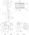
- Fig. 5 is schematically shown in a front view a turbine 100 that comprises a casing 10, at least a first stator (not shown in the figure), steadily connected to the turbine casing, a turbine shaft 15, rotating around an axis X and carrying at least a first rotor (not shown in the figure) and contained in a housing or tube member 20.
- the tube member 20 and consequently the shaft 15 are centered with respect to the turbine casing via centering means 30 which will be described below.
- both the casing 10 and the tube member 20 are provided with circular seats 60, 60' arranged along the centering circumference and angularly equidistant.
- the seats can be in number of three, at 120° from each other or in number of four, at 90° one from the other or even in a higher number.
- the seats 60, 60' accommodate corresponding centering bushings 50, 50'.
- bushings 50 or bushings 50' are provided with a slot 41, radially oriented.
- the centering system further comprises a plurality of centering tabs 40, each steadily connected (for example, by interference or bonding) to a centering bushing (in the example, to the bushing 50, accommodated in the turbine housing 10), said centering tabs leaving the tube member 20 free to move only in the radial direction, thanks to the presence of the slots 41 oriented radially, realized in the other set of centering bushings (the bushings 50' housed in the tube member 20, in the example in Fig. 6 ).
- a radial clearance 42 that allows the radial movement, as well as a small tangential clearance, namely a small clearance between the width of the tab 40 and the width of the seat of the bushing 50', so as to allow the relative displacement between the two parts in the radial direction.
- This clearance should be very small (of the order of hundredths of millimeter) since a larger clearance would affect the accuracy of the centering retention.
- the tabs located at 0° and 180° allow vertical displacements, while the tabs located at 90° and 270° allow horizontal displacements. In this way, a displacement due to thermal effects, radial and uniform with respect to the X axis of the machine, is allowed, but the shaft remains coaxial with the turbine casing.
- the centering system is highly precise; the realization of circular holes in the casing and in the tube member (instead of the realization of the centering slots) is much more precise and more simple; being small in size, differently from the casing 10 and the tube memeber 20, the centering bushings can be obtained from high-hardness material (for example, hardened steel) and realized with very small tolerances between the housing diameter in the seats 60, 60' and the slots 41 for the centering tabs 40.
- the centering bushings 50, 50' are provided with one or more grooves 51, in order to allow their precise positioning in the seats 60, 60' and maintain the bushings properly aligned.
- This groove will engage with a special system fixed to the tube member 20, for example with a plate 70' or ring that is fixed to the tube member by means of the screws 30".
- Figures 7a, 7b and 7c show a first embodiment of the centering between the centering tabs and the centering bushing.
- the tab 40 is forced into the bushing 50, housed in the casing 10 of the turbine 100, and is free to perform radial movements inside the slot 41 of the bushing 50 ', the one housed in the shaft tube member 20.
- Figures 8a to 8d show a second embodiment of the centering between the centering tabs and the centering bushing.
- the bushing 50' is provided with a centering slot 41, having dimensions A and B, being B> A, wherein B being the dimension that allows radial movement to the tab.
- the tab 50' is formed in a single piece with the bushing housed in the tube member 20 and is provided with a protrusion 40' which is housed in the slot 41 of the bushing 50' and has a radial dimension C ⁇ B.
- the dimension A' must be slightly inferior to A to allow the radial relative sliding of the two parts, but not too much smaller for not introducing a clearance that frustrates the maintenance of centering.
- the seats 60, 60' of the centering bushings can be realized, using different modes.
- a first embodiment is the one shown in Figure 9 .
- the two seats 60, 60', respectively in the casing 10 and in the shaft tube member 20, are two circular through-holes and facing one another.
- This solution although simple to implement because it does not involve changes to the flange portions between casing and tube member, would present risks of leakage of the working fluid, through the inevitable gaps that are created between the casing/tube member and the respective centering bushings. Therefore, in this solution the bushing 50 should be provided with a sealing system (not shown in Fig. 9 ).
- Fig. 10 the two embodiments shown in Fig. 10 are not subject to any kind of leakage of the fluid.
- the embodiment of Fig. 10a provides that the seat 60 of the bushing 50 of the casing 10 is a blind hole.
- the configuration of Fig. 10b requires the presence of a casing appendix 12, substantially annular shaped, within which the seat 60 is realized in the form of through hole. Therefore, both configurations achieve a perfect sealing of the working fluid with respect to the seat 60.
- the proposed solution allows to realize and maintain a good centering between the turbine shaft, with its housing, and the turbine casing even in the presence of high thermal gradients. Therefore, the present invention improves the centering process between the two parties, said centering resulting more reliable of the already known solutions, as well as cheap and easy to implement.
Landscapes
- Engineering & Computer Science (AREA)
- Mechanical Engineering (AREA)
- General Engineering & Computer Science (AREA)
- Turbine Rotor Nozzle Sealing (AREA)
Claims (10)
- Turbine (100) d'expansion d'un fluide de travail dans un cycle organique de Rankine, comprenant un boîtier (10) dans lequel est logé au moins un ensemble stator, un arbre de turbine (15) contenu dans un élément tubulaire (20) comprenant au moins un ensemble rotor contenu dans le boîtier (10), ledit élément tubulaire (20) et ledit boîtier (10) étant poussés réciproquement dans une direction axiale et centrés dans une direction radiale, ladite turbine étant caractérisée en ce que:- le centrage entre l'élément tubulaire (20) et le boîtier (10) est réalisé à l'aide de plusieurs tiges de centrage (40, 50") logées tour à tour dans des bagues de centrage correspondantes (50, 50') logées dans des logements correspondants (60, 60') formés dans le boîtier (10) et dans l'élément tubulaire (20), et que- lesdites tiges permettent un déplacement relatif dans la direction radiale, mais pas dans la direction tangentielle de l'élément tubulaire (20) par rapport au boîtier (10), et l'une desdites bagues de centrage (50, 50') est munie d'une fente (41), orientée radialement pour la tige de centrage (40, 50").
- Turbine (100) selon la revendication 1, dans laquelle lesdits logements (60, 60'), ladite bague (50) montée sur le boîtier (10) et la bague correspondante (50') montée sur l'élément tubulaire (20) sont disposés angulairement équidistants le long de la circonférence de centrage.
- Turbine (100) selon la revendication 1 ou 2, dans laquelle ledit logement (60) de la bague de centrage (50) du boîtier (10) est un trou borgne.
- Turbine (100) selon l'une des revendications précédentes, dans laquelle ledit logement (60) de la bague de centrage (50) du boîtier (10) est un trou traversant formé à l'intérieur d'un appendice (12) du boîtier, pourvu d'une forme sensiblement annulaire.
- Turbine (100) selon l'une des revendications précédentes, dans laquelle lesdites bagues de centrage (50, 50') sont pourvues d'une ou plusieurs rainures (51), qui permettent leur orientation correcte dans les logements (60, 60'), et lesdites rainures sont à leur tour maintenues en position par un système approprié pour maintenir la position.
- Turbine (100) selon la revendication 5, dans laquelle ledit système pour maintenir la position comprend une plaque (70') bloquée par des moyens de fixation appropriés (30").
- Turbine (100) selon la revendication 5 ou 6, dans laquelle ladite bague de centrage (40) est normalement reliée à l'une des deux bagues de centrage (50, 50') et est libre de se déplacer dans la direction radiale du l'intérieur de la rainure (41) disponible dans l'autre des deux bagues de centrage.
- Turbine (100) selon l'une des revendications 5 à 7, dans laquelle ladite bague de centrage (50") est formée d'une seule pièce avec la bague logée dans l'élément tubulaire (20) ou dans le boîtier (10), et est pourvu d'une saillie (40') logée dans la rainure (41) de la bague de centrage (50'), logée dans le boîtier (10) de l'élément tubulaire (20).
- Turbine (100) selon l'une des revendications précédentes, dans laquelle les bagues de centrage (50, 50') et les bagues (40, 50") sont réalisées en un matériau de grande dureté ou dans un matériau de base soumis à une traitement de surface, approprié pour augmenter la rigidité du matériau de base.
- Turbine (100) selon l'une des revendications précédentes, dans laquelle la distance entre la largeur de la bague de centrage (40, 50") et la largeur du logement de la bague de centrage (50, 50') est inférieure à 0,02 mm.
Applications Claiming Priority (2)
| Application Number | Priority Date | Filing Date | Title |
|---|---|---|---|
| ITUB20150651 | 2015-05-19 | ||
| PCT/IB2016/052828 WO2016185361A1 (fr) | 2015-05-19 | 2016-05-16 | Turbine pour cycles de rankine organiques ayant un centrage amélioré entre un boîtier et un élément de tube d'arbre |
Publications (2)
| Publication Number | Publication Date |
|---|---|
| EP3298248A1 EP3298248A1 (fr) | 2018-03-28 |
| EP3298248B1 true EP3298248B1 (fr) | 2020-01-15 |
Family
ID=53719867
Family Applications (1)
| Application Number | Title | Priority Date | Filing Date |
|---|---|---|---|
| EP16729376.0A Active EP3298248B1 (fr) | 2015-05-19 | 2016-05-16 | Turbine pour cycles de rankine organiques ayant un centrage amélioré entre un boîtier et un élément de tube d'arbre |
Country Status (2)
| Country | Link |
|---|---|
| EP (1) | EP3298248B1 (fr) |
| WO (1) | WO2016185361A1 (fr) |
Family Cites Families (3)
| Publication number | Priority date | Publication date | Assignee | Title |
|---|---|---|---|---|
| FR2911933B1 (fr) * | 2007-01-26 | 2009-05-01 | Snecma Sa | Dispositif d'assemblage de deux ensembles, par exemple pour stator de turbomachine |
| ITMI20110684A1 (it) * | 2011-04-21 | 2012-10-22 | Exergy Orc S R L | Impianto e processo per la produzione di energia tramite ciclo rankine organico |
| US9470151B2 (en) * | 2012-12-21 | 2016-10-18 | United Technologies Corporation | Alignment system and methodology to account for variation in a gas turbine engine |
-
2016
- 2016-05-16 EP EP16729376.0A patent/EP3298248B1/fr active Active
- 2016-05-16 WO PCT/IB2016/052828 patent/WO2016185361A1/fr not_active Ceased
Non-Patent Citations (1)
| Title |
|---|
| None * |
Also Published As
| Publication number | Publication date |
|---|---|
| WO2016185361A1 (fr) | 2016-11-24 |
| EP3298248A1 (fr) | 2018-03-28 |
Similar Documents
| Publication | Publication Date | Title |
|---|---|---|
| US9435217B2 (en) | Swirl interruption seal teeth for seal assembly | |
| CA2672096C (fr) | Contrefiche de conduit inter-turbine et aubage fixe pour turbine a gaz | |
| JP5021365B2 (ja) | 間隔可変のパッキンリング片組立体及びタービンダイヤフラム | |
| US3066911A (en) | Nozzle and turbine wheel shroud support | |
| JP6141871B2 (ja) | 高温気体膨張装置の入口ケーシング組立体及び方法 | |
| US9551224B2 (en) | Turbine and method for manufacturing turbine | |
| US9291066B2 (en) | Methods and systems for sealing a rotary machine using a segmented seal ring | |
| US8870533B2 (en) | Assembly for aligning an inner shell of a turbine casing | |
| JP2007298040A (ja) | 回転機械及びブリング組立体 | |
| JP2009008086A (ja) | ターボ機械ロータディスクのスロットを冷却する装置 | |
| JP6012505B2 (ja) | 軸シール装置及び回転機械 | |
| KR102105262B1 (ko) | 회전 기계 | |
| JP2011085136A (ja) | ターボ機械ロータ冷却 | |
| CN103195513B (zh) | 涡轮机组件和用于支撑涡轮机部件的方法 | |
| US9587499B2 (en) | Inner ring of a fluid flow machine and stator vane array | |
| EP3358142B1 (fr) | Contrôle de fuite à travers d'une virole d'aube de turbines | |
| JP5638696B2 (ja) | コンプレッサおよびこれに関連したガスタービン | |
| KR20170140347A (ko) | 시일 장치 및 회전 기계 | |
| EP3330491B1 (fr) | Aube fixée pour une machine rotative et machine rotative associée | |
| EP3298248B1 (fr) | Turbine pour cycles de rankine organiques ayant un centrage amélioré entre un boîtier et un élément de tube d'arbre | |
| CN105324554B (zh) | 轴流膨胀机 | |
| WO2002099253A1 (fr) | Turbine a gaz | |
| JP2011137455A (ja) | 内部反動蒸気タービン冷却方式 | |
| EP3265653B1 (fr) | Turbine pour cycles de rankine organiques à entrée et sortie axiales | |
| EP3284919B1 (fr) | Turbine à flux axial comportant un diaphragme divisé en deux moitiés au niveau d'un plan de séparation |
Legal Events
| Date | Code | Title | Description |
|---|---|---|---|
| STAA | Information on the status of an ep patent application or granted ep patent |
Free format text: STATUS: THE INTERNATIONAL PUBLICATION HAS BEEN MADE |
|
| PUAI | Public reference made under article 153(3) epc to a published international application that has entered the european phase |
Free format text: ORIGINAL CODE: 0009012 |
|
| STAA | Information on the status of an ep patent application or granted ep patent |
Free format text: STATUS: REQUEST FOR EXAMINATION WAS MADE |
|
| 17P | Request for examination filed |
Effective date: 20171128 |
|
| AK | Designated contracting states |
Kind code of ref document: A1 Designated state(s): AL AT BE BG CH CY CZ DE DK EE ES FI FR GB GR HR HU IE IS IT LI LT LU LV MC MK MT NL NO PL PT RO RS SE SI SK SM TR |
|
| AX | Request for extension of the european patent |
Extension state: BA ME |
|
| DAV | Request for validation of the european patent (deleted) | ||
| DAX | Request for extension of the european patent (deleted) | ||
| GRAP | Despatch of communication of intention to grant a patent |
Free format text: ORIGINAL CODE: EPIDOSNIGR1 |
|
| STAA | Information on the status of an ep patent application or granted ep patent |
Free format text: STATUS: GRANT OF PATENT IS INTENDED |
|
| INTG | Intention to grant announced |
Effective date: 20190814 |
|
| GRAS | Grant fee paid |
Free format text: ORIGINAL CODE: EPIDOSNIGR3 |
|
| GRAA | (expected) grant |
Free format text: ORIGINAL CODE: 0009210 |
|
| STAA | Information on the status of an ep patent application or granted ep patent |
Free format text: STATUS: THE PATENT HAS BEEN GRANTED |
|
| AK | Designated contracting states |
Kind code of ref document: B1 Designated state(s): AL AT BE BG CH CY CZ DE DK EE ES FI FR GB GR HR HU IE IS IT LI LT LU LV MC MK MT NL NO PL PT RO RS SE SI SK SM TR |
|
| REG | Reference to a national code |
Ref country code: CH Ref legal event code: EP Ref country code: GB Ref legal event code: FG4D |
|
| REG | Reference to a national code |
Ref country code: IE Ref legal event code: FG4D |
|
| REG | Reference to a national code |
Ref country code: DE Ref legal event code: R096 Ref document number: 602016028291 Country of ref document: DE |
|
| REG | Reference to a national code |
Ref country code: AT Ref legal event code: REF Ref document number: 1225327 Country of ref document: AT Kind code of ref document: T Effective date: 20200215 |
|
| REG | Reference to a national code |
Ref country code: NL Ref legal event code: MP Effective date: 20200115 |
|
| REG | Reference to a national code |
Ref country code: LT Ref legal event code: MG4D |
|
| PG25 | Lapsed in a contracting state [announced via postgrant information from national office to epo] |
Ref country code: FI Free format text: LAPSE BECAUSE OF FAILURE TO SUBMIT A TRANSLATION OF THE DESCRIPTION OR TO PAY THE FEE WITHIN THE PRESCRIBED TIME-LIMIT Effective date: 20200115 Ref country code: NO Free format text: LAPSE BECAUSE OF FAILURE TO SUBMIT A TRANSLATION OF THE DESCRIPTION OR TO PAY THE FEE WITHIN THE PRESCRIBED TIME-LIMIT Effective date: 20200415 Ref country code: RS Free format text: LAPSE BECAUSE OF FAILURE TO SUBMIT A TRANSLATION OF THE DESCRIPTION OR TO PAY THE FEE WITHIN THE PRESCRIBED TIME-LIMIT Effective date: 20200115 Ref country code: PT Free format text: LAPSE BECAUSE OF FAILURE TO SUBMIT A TRANSLATION OF THE DESCRIPTION OR TO PAY THE FEE WITHIN THE PRESCRIBED TIME-LIMIT Effective date: 20200607 Ref country code: NL Free format text: LAPSE BECAUSE OF FAILURE TO SUBMIT A TRANSLATION OF THE DESCRIPTION OR TO PAY THE FEE WITHIN THE PRESCRIBED TIME-LIMIT Effective date: 20200115 |
|
| PG25 | Lapsed in a contracting state [announced via postgrant information from national office to epo] |
Ref country code: IS Free format text: LAPSE BECAUSE OF FAILURE TO SUBMIT A TRANSLATION OF THE DESCRIPTION OR TO PAY THE FEE WITHIN THE PRESCRIBED TIME-LIMIT Effective date: 20200515 Ref country code: BG Free format text: LAPSE BECAUSE OF FAILURE TO SUBMIT A TRANSLATION OF THE DESCRIPTION OR TO PAY THE FEE WITHIN THE PRESCRIBED TIME-LIMIT Effective date: 20200415 Ref country code: GR Free format text: LAPSE BECAUSE OF FAILURE TO SUBMIT A TRANSLATION OF THE DESCRIPTION OR TO PAY THE FEE WITHIN THE PRESCRIBED TIME-LIMIT Effective date: 20200416 Ref country code: LV Free format text: LAPSE BECAUSE OF FAILURE TO SUBMIT A TRANSLATION OF THE DESCRIPTION OR TO PAY THE FEE WITHIN THE PRESCRIBED TIME-LIMIT Effective date: 20200115 Ref country code: SE Free format text: LAPSE BECAUSE OF FAILURE TO SUBMIT A TRANSLATION OF THE DESCRIPTION OR TO PAY THE FEE WITHIN THE PRESCRIBED TIME-LIMIT Effective date: 20200115 Ref country code: HR Free format text: LAPSE BECAUSE OF FAILURE TO SUBMIT A TRANSLATION OF THE DESCRIPTION OR TO PAY THE FEE WITHIN THE PRESCRIBED TIME-LIMIT Effective date: 20200115 |
|
| REG | Reference to a national code |
Ref country code: DE Ref legal event code: R097 Ref document number: 602016028291 Country of ref document: DE |
|
| PG25 | Lapsed in a contracting state [announced via postgrant information from national office to epo] |
Ref country code: DK Free format text: LAPSE BECAUSE OF FAILURE TO SUBMIT A TRANSLATION OF THE DESCRIPTION OR TO PAY THE FEE WITHIN THE PRESCRIBED TIME-LIMIT Effective date: 20200115 Ref country code: ES Free format text: LAPSE BECAUSE OF FAILURE TO SUBMIT A TRANSLATION OF THE DESCRIPTION OR TO PAY THE FEE WITHIN THE PRESCRIBED TIME-LIMIT Effective date: 20200115 Ref country code: LT Free format text: LAPSE BECAUSE OF FAILURE TO SUBMIT A TRANSLATION OF THE DESCRIPTION OR TO PAY THE FEE WITHIN THE PRESCRIBED TIME-LIMIT Effective date: 20200115 Ref country code: SK Free format text: LAPSE BECAUSE OF FAILURE TO SUBMIT A TRANSLATION OF THE DESCRIPTION OR TO PAY THE FEE WITHIN THE PRESCRIBED TIME-LIMIT Effective date: 20200115 Ref country code: RO Free format text: LAPSE BECAUSE OF FAILURE TO SUBMIT A TRANSLATION OF THE DESCRIPTION OR TO PAY THE FEE WITHIN THE PRESCRIBED TIME-LIMIT Effective date: 20200115 Ref country code: CZ Free format text: LAPSE BECAUSE OF FAILURE TO SUBMIT A TRANSLATION OF THE DESCRIPTION OR TO PAY THE FEE WITHIN THE PRESCRIBED TIME-LIMIT Effective date: 20200115 Ref country code: EE Free format text: LAPSE BECAUSE OF FAILURE TO SUBMIT A TRANSLATION OF THE DESCRIPTION OR TO PAY THE FEE WITHIN THE PRESCRIBED TIME-LIMIT Effective date: 20200115 Ref country code: SM Free format text: LAPSE BECAUSE OF FAILURE TO SUBMIT A TRANSLATION OF THE DESCRIPTION OR TO PAY THE FEE WITHIN THE PRESCRIBED TIME-LIMIT Effective date: 20200115 |
|
| REG | Reference to a national code |
Ref country code: AT Ref legal event code: MK05 Ref document number: 1225327 Country of ref document: AT Kind code of ref document: T Effective date: 20200115 |
|
| PLBE | No opposition filed within time limit |
Free format text: ORIGINAL CODE: 0009261 |
|
| STAA | Information on the status of an ep patent application or granted ep patent |
Free format text: STATUS: NO OPPOSITION FILED WITHIN TIME LIMIT |
|
| 26N | No opposition filed |
Effective date: 20201016 |
|
| PG25 | Lapsed in a contracting state [announced via postgrant information from national office to epo] |
Ref country code: LI Free format text: LAPSE BECAUSE OF NON-PAYMENT OF DUE FEES Effective date: 20200531 Ref country code: CH Free format text: LAPSE BECAUSE OF NON-PAYMENT OF DUE FEES Effective date: 20200531 Ref country code: MC Free format text: LAPSE BECAUSE OF FAILURE TO SUBMIT A TRANSLATION OF THE DESCRIPTION OR TO PAY THE FEE WITHIN THE PRESCRIBED TIME-LIMIT Effective date: 20200115 Ref country code: AT Free format text: LAPSE BECAUSE OF FAILURE TO SUBMIT A TRANSLATION OF THE DESCRIPTION OR TO PAY THE FEE WITHIN THE PRESCRIBED TIME-LIMIT Effective date: 20200115 |
|
| PG25 | Lapsed in a contracting state [announced via postgrant information from national office to epo] |
Ref country code: PL Free format text: LAPSE BECAUSE OF FAILURE TO SUBMIT A TRANSLATION OF THE DESCRIPTION OR TO PAY THE FEE WITHIN THE PRESCRIBED TIME-LIMIT Effective date: 20200115 Ref country code: SI Free format text: LAPSE BECAUSE OF FAILURE TO SUBMIT A TRANSLATION OF THE DESCRIPTION OR TO PAY THE FEE WITHIN THE PRESCRIBED TIME-LIMIT Effective date: 20200115 |
|
| REG | Reference to a national code |
Ref country code: BE Ref legal event code: MM Effective date: 20200531 |
|
| PG25 | Lapsed in a contracting state [announced via postgrant information from national office to epo] |
Ref country code: LU Free format text: LAPSE BECAUSE OF NON-PAYMENT OF DUE FEES Effective date: 20200516 |
|
| PG25 | Lapsed in a contracting state [announced via postgrant information from national office to epo] |
Ref country code: IE Free format text: LAPSE BECAUSE OF NON-PAYMENT OF DUE FEES Effective date: 20200516 |
|
| PG25 | Lapsed in a contracting state [announced via postgrant information from national office to epo] |
Ref country code: BE Free format text: LAPSE BECAUSE OF NON-PAYMENT OF DUE FEES Effective date: 20200531 |
|
| PG25 | Lapsed in a contracting state [announced via postgrant information from national office to epo] |
Ref country code: MT Free format text: LAPSE BECAUSE OF FAILURE TO SUBMIT A TRANSLATION OF THE DESCRIPTION OR TO PAY THE FEE WITHIN THE PRESCRIBED TIME-LIMIT Effective date: 20200115 Ref country code: CY Free format text: LAPSE BECAUSE OF FAILURE TO SUBMIT A TRANSLATION OF THE DESCRIPTION OR TO PAY THE FEE WITHIN THE PRESCRIBED TIME-LIMIT Effective date: 20200115 |
|
| PG25 | Lapsed in a contracting state [announced via postgrant information from national office to epo] |
Ref country code: MK Free format text: LAPSE BECAUSE OF FAILURE TO SUBMIT A TRANSLATION OF THE DESCRIPTION OR TO PAY THE FEE WITHIN THE PRESCRIBED TIME-LIMIT Effective date: 20200115 Ref country code: AL Free format text: LAPSE BECAUSE OF FAILURE TO SUBMIT A TRANSLATION OF THE DESCRIPTION OR TO PAY THE FEE WITHIN THE PRESCRIBED TIME-LIMIT Effective date: 20200115 |
|
| P01 | Opt-out of the competence of the unified patent court (upc) registered |
Effective date: 20230530 |
|
| PGFP | Annual fee paid to national office [announced via postgrant information from national office to epo] |
Ref country code: DE Payment date: 20250422 Year of fee payment: 10 |
|
| PGFP | Annual fee paid to national office [announced via postgrant information from national office to epo] |
Ref country code: GB Payment date: 20250411 Year of fee payment: 10 |
|
| PGFP | Annual fee paid to national office [announced via postgrant information from national office to epo] |
Ref country code: IT Payment date: 20250417 Year of fee payment: 10 |
|
| PGFP | Annual fee paid to national office [announced via postgrant information from national office to epo] |
Ref country code: FR Payment date: 20250411 Year of fee payment: 10 |
|
| PGFP | Annual fee paid to national office [announced via postgrant information from national office to epo] |
Ref country code: TR Payment date: 20250513 Year of fee payment: 10 |