EP3298300B1 - Procédé de commande pour un dispositif amortisseur - Google Patents
Procédé de commande pour un dispositif amortisseur Download PDFInfo
- Publication number
- EP3298300B1 EP3298300B1 EP16727965.2A EP16727965A EP3298300B1 EP 3298300 B1 EP3298300 B1 EP 3298300B1 EP 16727965 A EP16727965 A EP 16727965A EP 3298300 B1 EP3298300 B1 EP 3298300B1
- Authority
- EP
- European Patent Office
- Prior art keywords
- data set
- damper
- measurement data
- damping
- control
- Prior art date
- Legal status (The legal status is an assumption and is not a legal conclusion. Google has not performed a legal analysis and makes no representation as to the accuracy of the status listed.)
- Active
Links
Images


Classifications
-
- F—MECHANICAL ENGINEERING; LIGHTING; HEATING; WEAPONS; BLASTING
- F16—ENGINEERING ELEMENTS AND UNITS; GENERAL MEASURES FOR PRODUCING AND MAINTAINING EFFECTIVE FUNCTIONING OF MACHINES OR INSTALLATIONS; THERMAL INSULATION IN GENERAL
- F16F—SPRINGS; SHOCK-ABSORBERS; MEANS FOR DAMPING VIBRATION
- F16F15/00—Suppression of vibrations in systems; Means or arrangements for avoiding or reducing out-of-balance forces, e.g. due to motion
- F16F15/002—Suppression of vibrations in systems; Means or arrangements for avoiding or reducing out-of-balance forces, e.g. due to motion characterised by the control method or circuitry
-
- F—MECHANICAL ENGINEERING; LIGHTING; HEATING; WEAPONS; BLASTING
- F16—ENGINEERING ELEMENTS AND UNITS; GENERAL MEASURES FOR PRODUCING AND MAINTAINING EFFECTIVE FUNCTIONING OF MACHINES OR INSTALLATIONS; THERMAL INSULATION IN GENERAL
- F16F—SPRINGS; SHOCK-ABSORBERS; MEANS FOR DAMPING VIBRATION
- F16F9/00—Springs, vibration-dampers, shock-absorbers, or similarly-constructed movement-dampers using a fluid or the equivalent as damping medium
- F16F9/32—Details
- F16F9/3292—Sensor arrangements
-
- F—MECHANICAL ENGINEERING; LIGHTING; HEATING; WEAPONS; BLASTING
- F16—ENGINEERING ELEMENTS AND UNITS; GENERAL MEASURES FOR PRODUCING AND MAINTAINING EFFECTIVE FUNCTIONING OF MACHINES OR INSTALLATIONS; THERMAL INSULATION IN GENERAL
- F16F—SPRINGS; SHOCK-ABSORBERS; MEANS FOR DAMPING VIBRATION
- F16F9/00—Springs, vibration-dampers, shock-absorbers, or similarly-constructed movement-dampers using a fluid or the equivalent as damping medium
- F16F9/32—Details
- F16F9/53—Means for adjusting damping characteristics by varying fluid viscosity, e.g. electromagnetically
- F16F9/535—Magnetorheological [MR] fluid dampers
Definitions
- the present invention relates to a method for controlling a damper device.
- the damper device has two connection units that can be moved relative to one another, between which at least one controllable damper is provided for damping relative movements, the damper having at least one first damper chamber and at least one associated damping valve.
- the damping valve has a damping channel with a magnetorheological fluid.
- a magnetic field generating device is assigned to the damping valve and is used to generate and control a magnetic field. A type of opening state of the damping valve is thus influenced.
- Damping in the form of vibrations and/or shocks has a major impact on e.g. B. the driving characteristics of vehicles and is therefore an important feature, especially in sporty vehicles.
- the use of a damper enables improved ground contact and allows sporty driving even on winding roads.
- Magnetorheological dampers on the wheels that switch in milliseconds enable comfortable and safe operation.
- the steering column or in seat belts for energy absorption in accidents allow such magnetorheological dampers optimal adaptation to the accident scenario and thus the least possible injuries to the occupants.
- the damping device comprises a controllable damping valve with a field generating device, with which a field-sensitive medium such as a magnetorheological fluid can be influenced in order to influence the damping force of the damping device by applying a field strength of the field generating device .
- the damping force of the damper device is adjusted in real time.
- the damper is not set to a specific type of road, but adapts to the current condition at any time. For this purpose, events in the form of impacts are recognized and a relative speed of the damper ends is periodically recorded.
- a characteristic value is derived in real time from the relative speed and, in turn, a field strength to be set is derived from a damping characteristic curve using the characteristic value.
- the field strength to be set is generated in real time with the field generating device in order to immediately and automatically set the damping force.
- the well-known damper device works very reliably and switches within a few milliseconds and much faster than the prior art, so that the damper device z. B. when cycling while driving over a root or a stone is continuously adapted to the currently prevailing conditions. For example, when driving on a slippery road surface, the damper remains set hard so that drive energy is not unnecessarily dissipated in the damper device. In principle, the damper device works very satisfactorily. However, it turned out that in In some situations, for example when the shock absorber on a bicycle is slowly compressed manually, the shock absorber does not compress softly, which the shock absorber should allow at a low compression speed, but gives a scratchy or scraping feedback to the user's hand.
- the measurement data was filtered, but this led to a considerable time delay in the reaction of the damping device, which was disadvantageous in terms of driving dynamics or performance, as a result of which shocks were cushioned too late and large shocks were not cushioned in good time. This all takes place in the range of microseconds.
- the measuring frequency was increased in order to obtain the correct reaction of the damping device at all times and thus a smoother transition in all areas due to a faster sequence of the measured values. But even increasing the measurement frequency did not bring any improvement in compression and rebound behavior. And that despite the fact that the damping device can be fully adjusted within a few milliseconds.
- the method according to the invention serves to control the damping of a relative movement of two connection units that can be moved relative to one another, between which at least one controllable damper with a damping valve with a magneto-rheological medium, fluid or damping fluid is provided for damping the relative movements.
- At least one magnetic field generating device for generating and controlling a magnetic field is assigned to the at least one damping valve.
- Measurement data records are recorded at least via a relative movement of the connection units to one another and processed with a filter device.
- a derived data set includes in particular (a value for) a speed signal and (a value for) an acceleration signal for a relative movement of the connection units.
- At least one data set derived from a recorded measurement data set is stored in the memory device.
- At least one stored data set is analyzed and a set of filter parameters is determined depending on the result of the analysis.
- a filter parameter set with stronger filtering is selected and in the case of speed signals that are larger in magnitude or acceleration signals that are larger in terms of magnitude, a filter parameter set with less filtering is selected.
- a control data set is derived from the measurement data set with the filter parameter set. The control device uses the control data set to control the damper device at least partially and in particular also completely.
- the method according to the invention offers many advantages, since it performs processing that is adapted as a function of the analysis of the measurement data, as a result of which suitable damping parameters can be set at any time.
- the method according to the invention is carried out with a damping device which comprises two connection units which can be moved relative to one another, between which, in order to dampen relative movements such as e.g. B. shocks or vibrations at least one controllable damper is provided with a magnetorheological medium, fluid or damping fluid.
- the damper has at least one first damper chamber and at least one damping valve connected thereto.
- At least one magnetic field generating device is assigned to the at least one damping valve, which is used to generate and control a magnetic field in at least one damping channel of the damping valve.
- the or at least one magnetorheological fluid is at least partially provided in the damping channel.
- At least one control device and at least one memory device are also provided.
- At least one sensor device is provided for acquiring measurement data sets at least via a relative movement of the connection units to one another.
- a plurality of data sets can preferably be stored in the memory device.
- a filter device is provided for processing the measurement data records.
- At least one data record derived from a measurement data record recorded with the sensor device during the relative movement of the connection units that can be moved relative to one another can be stored in the memory device.
- the measurement data set and/or the derived data set includes at least one speed signal and/or at least one acceleration signal for the movement of the connection units relative to one another.
- An analysis device is provided, which is designed and set up to analyze at least one stored data set and to determine a filter parameter set depending on the result of the analysis.
- the control device for this formed, in terms of absolute value low speed signals and acceleration signals, a filter parameter set with stronger filtering and, in the case of speed signals or acceleration signals that are larger in absolute value, a filter parameter set with less filtering.
- the control device is designed to use the filter parameter set to derive a control data set from the measurement data set, so that the control device uses the control data set to control the damper device at least partially or completely.
- Controlling the damper device using the method according to the invention has many advantages.
- a significant advantage of controlling the damper device is that the analysis device analyzes the recorded measurement data sets, so that a filter parameter set is determined depending on the result of the analysis, with which a control data set is derived from the measurement data set, with which the damping valve of the magnetorheological damper is at least partially controlled.
- a suitable set of filter parameters is determined by analyzing the measurement datasets of the relative movement of the connection units that can be moved relative to one another, in order to ensure a rapid response behavior of the damper device that is sufficiently soft in all situations.
- the term data set is understood to mean a data set with at least one value or measured value contained therein. It is also possible and preferred that a data set contains several different values or parameters.
- a measurement data set can contain distance information and speed information as well as acceleration information and the like. However, it is also possible for a measurement data set to contain only a single measured value. The same also applies to a derived data set that is stored in the storage device and also to a control data set that is determined from the stored data set and/or the measurement data set.
- a filter parameter set may contain one or more filter parameters.
- a set of parameters preferably includes several parameters. However, it is also possible for a parameter set to contain only one parameter.
- a derived data record that is stored in the memory device is also referred to below as a “stored data record”.
- the derived and stored data set can be identical to the associated measurement data set or is obtained from it through processing. For example, a normalization can be carried out.
- control device is designed and set up to analyze at least one stored data set and, depending on the result of the analysis, to determine a filter parameter set from a plurality of filter parameter sets and to derive a control data set from the measurement data set using the determined filter parameter set.
- the filter device filters measurement data less intensively when there is a more intensive movement of the connection units relative to one another.
- a more intensive relative movement is understood to mean a faster relative movement or a faster acceleration relative to one another or possibly also an absolute speed or acceleration.
- the filtering is more intensive. This means that the measurement data or the value or values of a measurement data set are denoised to a greater extent. This can provide a smoother timing.
- the control device controls the damper device directly or indirectly using further components such as (power) electronics and in particular using a magnetic field generating device. In any case, the damping of the damping device is adjusted with the control data record.
- Prepared data records are obtained from the measurement data records by preparation and/or by pre-filtering and/or by filtering, which preferably form the basis for further processing be placed.
- the measurement of the measurement data records is preferably carried out with a frequency that is greater than 200 Hz or 500 Hz and in particular greater than 1 kHz.
- Both the current measurement data set and at least one previous measurement data set or at least the current derived data set and/or at least one previously derived data set can be stored in the memory device. It is also possible and preferred that the respectively current control data set is stored in the memory device.
- a preset filter parameter set is preferably loaded and at least one first measurement data set is recorded.
- a control data set with the preset filter parameter set is derived from the measurement data set.
- a new or current measurement data record is then recorded in a loop.
- a filter parameter set is then selected or derived from the preceding control data set.
- a current control data set is derived with the filter parameter set determined in this way. The damping of the damper device is adjusted taking into account this control data set or with this control data set.
- the measurement data set that was still current becomes the previous measurement data set.
- the current measurement data record is recorded.
- a filter parameter set is selected via the control data set of a preceding loop and in particular the last loop, and a current control data set is derived with the current measurement data set and the selected filter parameter set, with the aid of which the damping is then adjusted.
- a current measurement data record is also initially recorded.
- a filter parameter set is selected via the current measurement data set and a current control data set is derived from the current measurement data set using the selected filter parameter set.
- the damping is then set taking into account the current control data record.
- the filter parameter set can possibly also be determined iteratively.
- a new partial loop run is carried out to determine the filter parameter set if the currently determined control data set deviates from the previous control data set by a certain amount or if the control data set or the values contained therein fall below or exceed certain limits.
- a current measurement data set is first recorded and a current control data set is derived from the current measurement data set using the previous filter parameter set.
- the control data set is then used to check whether the correct filter parameter set was selected.
- the filter parameter set is possibly reselected and a new control data set or current control data set is derived again.
- a check can also be carried out here as to whether the correct filter parameter set has been selected.
- This iteration loop can be repeated any number of times. Preferably, the iteration loop is limited in number to avoid a persistent loop. Finally, the damping is set with the current control data record.
- a plurality of filter parameter sets are stored in the storage device and a filter parameter set can be selected as a function of the at least one stored data set.
- the stored data record can be the measurement data record as it is recorded. But it is also possible that with the sensor device the recorded measurement data set is processed in a first processing step in order to obtain, for example, standardized values and then to store the data set determined in this way in the storage device.
- a plurality of data sets that have been measured and processed together are preferably stored in the storage device. Depending on the storage capacity, a FIFO method can be selected so that a number of the most recent measurement data sets remain in the storage device.
- the analysis device comprises a comparison device and the comparison device compares a stored data set with comparison data and, depending on the result of the comparison, selects a filter parameter set stored in the memory device or derives a filter parameter set and derives a control data set from the measurement data set with the filter parameter set .
- a set of filter parameters can preferably be selected as a function of the at least one stored data record. This means that a filter parameter set can be selected depending on the content of at least one stored data record. Accordingly, the content of a stored data record can be compared with comparison data using the comparison device.
- a plurality of data sets can be stored in the memory device.
- this also includes the data records derived from them and stored in the memory device, as well as the control data records that can be stored in the memory device and possibly the like.
- the sensor device is particularly preferably designed to detect at least one displacement signal.
- the control device is designed to derive a speed signal for a relative movement of the connection units from a sensor signal (in particular that of the sensor device).
- a computing unit is provided, which can be part of the control device.
- the control device is preferably designed to derive an acceleration signal from a sensor signal (in particular that of the sensor device).
- the control device is designed and set up to derive an acceleration signal of the required quality from a sensor signal.
- the control device determines the acceleration signal from the sensor signal at a frequency of preferably greater than 1 kHz.
- a computing unit which can also be part of the control device, is preferably also provided for calculating the acceleration signal. The same computing unit can be used to calculate the acceleration signal and the speed signal.
- the damper device is controlled in particular in real time. This means that a damping is set at any time that is necessary and sensible for the current load situation.
- the damper device is not set to a suitable “average value”, but the sensor device is read out at any time (periodically at 1 kHz or more) and speed signals and/or acceleration signals are recorded and derived in particular from displacement signals.
- a suitable damping for the current speed signal is now set in real time at any point in time, since the damping device can be freely adjusted in a few milliseconds.
- the unclaimed control device is designed to select a filter parameter set with stronger filtering in the case of speed signals and acceleration signals that are low in terms of absolute value.
- the control device is preferably designed to select a filter parameter set with less filtering in the case of speed signals or acceleration signals that are larger in terms of absolute value. That means a Filter parameter set with stronger filtering is selected when the velocity signal and the acceleration signal are small. A filter parameter set with less filtering is selected even if only one of the two signals, namely the speed signal and the acceleration signal, is larger. This ensures a very fast response to bumps, while smoothing out more with low signals. However, this prevents a (too) late reaction to a strong impact.
- Such chattering has been found to occur particularly when the speed signal is below 10% and more likely below 5% of the maximum speed signal typical of operation.
- the maximum occurring speed signal z. B. is about 0.5 m / s or 1 m / s
- a "scratch" can occur in particular with speed signals of up to 0.05 or 0.02 m / s.
- speed signals below a predetermined limit are filtered more intensively, so that noise is removed more intensively.
- the speed signals are higher, there is less filtering or no filtering at all.
- the speed signal is filtered less intensively, even if the absolute value is small. This combination achieves an optimal result.
- the sensor device is advantageously suitable and designed to detect the displacement signal with a resolution of better than 100 ⁇ m.
- the resolution of the path signal can also be better than 50 ⁇ m or better than 30 ⁇ m and preferably better than 10 ⁇ m be.
- the chassis can be controlled very precisely.
- the sensor device is suitable and designed to acquire the sensor signal with a measurement frequency of at least 500 Hz or at least 1 kHz.
- the measuring frequency can also reach or exceed 5 kHz.
- the damper comprises at least one second damper chamber in addition to the first damper chamber.
- the first damper chamber and the second damper chamber are coupled to one another via at least one damping valve or one controllable damping valve in particular.
- the at least one damping valve or at least one damping valve is assigned at least one magnetic field generating device, which is used to generate and control a magnetic field in at least one damping channel of the damping valve.
- At least one magnetorheological fluid or medium in general is particularly preferably provided in the damping channel. By means of a magnetorheological medium in the damping channel, at least one property of the damping device can be set individually and quickly by controlling the magnetic field generating device. The damping force of the damper or damper device can be completely readjusted within a few milliseconds.
- At least one speed signal or speed data is derived from the measurement data set.
- at least one acceleration signal or acceleration data can be derived from the measurement data set.
- a measurement data record or at least one value of a measurement data record is filtered more intensively when the absolute value of the respective value of the measurement data record is smaller than when the magnitude of the value or values of the measurement dataset is greater. Threshold values or a set of limit values can be provided to differentiate whether stronger or weaker filtering is carried out.
- the values of the measurement data set can contain path values, acceleration values and/or speed values. Filtering can also be understood as smoothing the values.
- amount of values means the mathematical amount - i.e. unsigned.
- the relative movement is filtered more strongly at low speeds than at high speeds.
- the speed signal is taken into account in order to decide whether filtering is stronger or weaker.
- the relative movement is filtered more strongly in the case of low accelerations or acceleration signals than in the case of high accelerations or high acceleration signals.
- stronger filtering is understood here to mean more intensive filtering. This means that more heavily filtered measurement data are denoised more intensively. This can be done, for example, by considering a larger number of previous measurement data or by considering previous measurement data with a higher weighting. More filtering results in more smoothing than less filtering. This leads to a lower cut-off frequency. Edges become more rounded with stronger filtering than with weaker filtering, where the cutoff frequency is higher. Stronger filtering leads in particular to stronger denoising than weaker filtering. Velocity signals and acceleration signals are particularly preferably taken into account in order to decide how strong the filtering is. When the speed signal exceeds a predetermined speed limit or when the acceleration signal exceeds a predetermined acceleration limit exceeds, the filtering is weaker than if the speed signal and the acceleration signal are smaller than the respective limit.
- the measurement frequency must be high enough to allow a sufficiently quick reaction to all events to be expected at any time. So must a damping device when a shock occurs when z. E.g. driving over a bumper, a pothole, a root or a jump so quickly react and choose the right one Make damper settings that optimal or at least adequate damping properties are present.
- z. B. in motor vehicles according to the prior art today regularly not, since there no shock is damped in real time or can be damped due to the "slow" damper, but at most the general damper setting is changed.
- the damper setting of the damper device is adjusted many times during an impact in order to have optimal damper settings in each case.
- the measuring frequency and the controller frequency of the control device must therefore be correspondingly high in order to implement the concept with high dynamics.
- At least a plurality of data sets recorded one after the other are stored in the memory device.
- Measurements is output as a measurement data record.
- Such "oversampling” can be carried out both on the hardware and software side. It is important that the output rate of the measurement datasets is fast enough.
- a strength or intensity of the smoothing preferably depends on the stored data set.
- strengthening the smoothing depends on the current dataset.
- the number of data sets used for the averaging is varied. Will, for example, stronger filtering desired, the smoothing can be carried out over a correspondingly larger number of data sets recorded one after the other, while with weaker filtering a correspondingly smaller number of data sets is taken into account for the averaging.
- the proportional factors for sliding averaging are varied as a function of the strength of the desired filtering.
- neighboring or previous measured values can be taken into account with the same weighting or a similar weighting as the current measured value.
- the current measured value and the previous 4 values (10 values) can each be taken into account at 20% (10%) for stronger filtering.
- weaker filtering on the other hand, (fewer measured values and) measured values that are further apart in time can be taken into account with a lower proportional factor.
- the current measured value can be taken into account with 75% and the previous measured value with 25%. Or the current measured value and the one before it are each taken into account with 50%, while with stronger filtering the current measured value and the two measured values before that are each taken into account with the same weighting (33%).
- IIR filters Infinite Impulse Response
- FIR filters Finite Impulse Response
- Kalman filter is also preferred, in which case at least one parameter of the Kalman filter is then varied with the strength of the filtering.
- the sensor device records measurement data sets with a measurement frequency greater than 250 Hz (in particular 500 Hz and preferably 1 kHz) and/or that the control device records control data sets with a control frequency greater than 250 Hz (in particular 500 Hz and preferably 1 kHz) determined.
- the damper device is at least temporarily with at least this Control frequency of 250 Hz (particularly 500 Hz and preferably 1 kHz) driven.
- the measuring frequency and the control frequency are particularly preferably >2 kHz.
- the measurement frequency and/or the control frequency are preferably greater than 5 kHz.
- the sensor device particularly preferably detects path signals with a resolution of less than 100 ⁇ m or less than 50 ⁇ m. A resolution of less than 30 ⁇ m and particularly preferably less than 10 ⁇ m is preferably achieved. This allows high-resolution relative movements to be determined, which increases accuracy.
- the measuring frequency and the control frequency are at least temporarily greater than 8 kHz and the resolution of the displacement signals is at least temporarily less than 10 ⁇ m or 5 ⁇ m.
- the measurement frequency is less than 50 kHz and preferably less than 20 kHz or if measurement data sets are output at a frequency of less than 50 kHz and preferably less than 20 kHz.
- the measurement frequency and the control frequency are different.
- the measurement frequency is preferably greater than the control frequency.
- the control frequency is preferably greater than 50 Hz and in particular greater than 100 Hz and preferably greater than 250 Hz or greater than 500 Hz.
- the measuring frequency is in particular greater than 250 Hz and preferably greater than 500 Hz and particularly preferably greater than 1 kHz.
- a ratio of measurement frequency to control frequency can be greater than 2 and in particular greater than 4 and preferably greater than 8 or 16.
- the invention makes available an advantageous method and an advantageous damper device, with which an adapted and respectively smooth response behavior is made possible in all load ranges.
- the recording of measured values was not too slow before, but rather too fast at low damper speeds, since also due to the noise that inevitably occurs, which is at least partly also caused by digitization effects, with increasing measuring frequency at low rates of change of the measured variables, the relative errors increase, which is why the damper set the noisy values too quickly due to its high reaction speed.
- the measured values change from one step to the next at such a speed that the digitization does not introduce any significant errors.
- an unclaimed damper device comprises two connection units that can be moved relative to one another, between which, for damping relative movements such as e.g. B. shocks or vibrations at least one controllable magnetorheological damper is provided.
- At least one control device and at least one memory device are provided.
- At least one sensor device is provided for acquiring measurement data sets at least via a relative movement of the connection units to one another.
- a filter device is provided for processing the measurement data records. At least one data record derived from a measurement data record recorded with the sensor device during the relative movement of the connection units that can be moved relative to one another can be stored in the memory device.
- An analysis device is provided, which is designed and set up to analyze at least one stored data set and, depending on the result of the analysis, to determine a filter parameter set and to derive a control data set from the measurement data set using the filter parameter set, so that the control device uses the control data set to control the damper device at least partially or fully controlled. Developments contain some or all of the features of the damper device described above.
- An increase in measurement accuracy has also proven advantageous and/or the measurement resolution.
- a coordinated adjustment of measurement resolution and measurement frequency and filtering of the measurement data after analysis of the measurement data are particularly advantageous.
- the evaluation takes place in real time.
- the filter device it is preferably possible for the filter device to be integrated into the control device.
- the filtering can be carried out at least partially or completely by a computing unit of the control device.
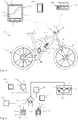
- damping device 100 is used on a bicycle 200 here.
- FIG. 1 shows a schematic representation of a bicycle 200, which is designed here as a mountain bike and has a frame 113 and a front wheel 111 and a rear wheel 112. Both the front wheel 111 and the rear wheel 112 are equipped with spokes and can have the disc brakes shown. A gear shift is used to select the gear ratio. Furthermore, the bicycle 200 has a steering device 116 with a handlebar and a saddle 117 .
- the front wheel 111 has a damper device 100 designed as a spring fork 114 and a damper device 100 designed as a rear wheel damper 115 is provided on the rear wheel 112 .
- the damper device 100 comprises a damper 1 and a control device 46. It is also possible for the damper device 100 to comprise two dampers 1 (spring fork and rear wheel shock absorber), on each of which a control device 46 is provided. Or the damper device 100 comprises two dampers 1 and a (central) control device 60. The (central) control device 60 can be used to set the specifications and to coordinate the two dampers.
- the central control device 60 is provided here together with a battery unit 61 in a drinking bottle-like container and is arranged on the down tube where a drinking bottle is otherwise arranged, but can also be provided in the frame.
- the central control device 60 can also be arranged on the handlebar 116 .
- the damper 1 and other bicycle components can be controlled as a function of a wide variety of parameters and is also essentially based on data recorded by sensors. In particular, aging of the damping medium, the spring device and other components can also be taken into account. It is also preferable to consider the temperature of the damper device 100 or the damper 1 (spring fork 114 and/or rear wheel shock absorber 115).
- the damper device 100 and its central control device 60 are operated via operating devices 150 .
- Two operating devices 150 are provided, namely an operating device 151 and an adjusting device 152.
- the operating device 151 has mechanical input units 153 at the lateral ends or in the vicinity of the lateral ends of the handlebar 116.
- the adjustment device 152 can be designed as a bicycle computer and can have a touch-sensitive screen and can also be positioned on the handlebar 116 .
- a smartphone 160 or a tablet or the like to be used as the setting device 152 and to be kept in the user's pocket or backpack, for example, if the settings are not changed.
- the display 49 is designed in particular as a graphical control unit or touchscreen 57 so that the user can touch a displayed characteristic damper curve 10 with his fingers and change it by dragging.
- damper characteristic curve 50 which is also shown, can be generated from damper characteristic curve 10, which is shown as a solid line, and is then used immediately for the control.
- the damper characteristics 10, 50 can also be changed while driving.
- the setting device 152 can also serve as a bicycle computer and display information about the current speed, as well as the average speed and/or the daily, tour, lap and total kilometers. It is also possible to display the current position, the current altitude of the route driven and the route profile and also a possible range under the current attenuation conditions.
- FIG 2 shows a schematic representation of the control of the damper device 100 and the communication connections of some components involved.
- the central control device 60 can be wired or wirelessly connected to the individual components.
- the control device 60 (or 46) can be connected to the other components via WLAN, Bluetooth, ANT+, GPRS, UMTS, LTE or other transmission standards. If necessary, the control device 60 can be wirelessly connected to the Internet 53 via the connection shown in dotted lines.
- the control devices 46 and/or 60 are connected to at least one sensor device 20 or to a plurality of sensors.
- the control device 60 is connected via network interfaces 54 or radio network interfaces 55 to control devices 46 of the dampers 1 on the front wheel and on the rear wheel.
- the control device 46 possibly provided on each damper 1 ensures local control and can each have a battery or be connected to the central battery unit 61 . It is preferred that both dampers are controlled via the control device 60 . Local control of the dampers 1 via an associated control device 46 is also possible.
- At least one sensor device 20 is preferably assigned to each damper 1 in order to detect relative movements between the components or connection units 101 and 102 . In particular, a relative position of the components 101 and 102 relative to one another can be determined.
- the sensor device 20 is preferably designed as a (relative) travel sensor or comprises at least one such and is integrated into the damper 100 .
- the use of at least one additional acceleration sensor 47 is also possible and preferred.
- the sensor device 20 can also preferably be designed as a speed sensor or include such a sensor.
- a suitable spring force can be determined via the weight of the driver.
- the weight of the driver can be derived by automatically determining the compression position (sag) after a driver touches down.
- a suitable air pressure in the fluid spring or gas spring can be deduced from the deflection travel when the rider places himself on the bicycle, which is then automatically set or approximated immediately or in the course of operation.
- control circuit 12 is shown schematically, which is stored in the memory device 45 and stored in the control device 46 or 60 or programmed. The control circuit 12 is carried out periodically and in particular continuously periodically during operation.
- a current relative movement or relative speed of the first component or connection unit 101 to the second component or connection unit 102 is detected with the sensor device 20 .
- a characteristic value is derived from the values of the sensor device 20, which is representative of the current relative speed. A relative speed is preferably used as the characteristic value.
- the (cf. 3 ) Damper 1 has a first and a second damper chamber, between which a damping valve 8 is arranged.
- the damping valve 8 has at least one damping channel 7 which is exposed to a magnetic field of an electric coil device in order to influence the magneto-rheological medium or fluid (MRF) in the damping channel 7 and thus set the desired damping force.
- MRF magneto-rheological medium or fluid
- step 56 the associated damping force to be set is then derived from the current measured values, taking into account the predetermined or selected damper characteristic.
- a measure for the current field strength or current strength to be set is derived from this, with which the damping force to be set is at least approximately achieved.
- the measure can be the field strength itself or z.
- the current field strength to be set is generated or the corresponding current strength is applied to the electrical coil device 11 as the field generation device, so that within a single cycle or a time period of the control circuit 12, the damping force is generated which, with the selected or predetermined damping characteristic for the current relative speed of the first connection unit 101 to the second connection unit 102 is provided.
- the next cycle then starts and step 52 is carried out again.
- each cycle takes less than 30 ms and in particular less than 20 ms. It is possible that the acquisition of the sensor data and the subsequent calculations are carried out at a higher speed (e.g. a particularly integer multiple of the measurement frequency).
- FIG 3 shows an embodiment of a damper device 100 with a damper 1 and here with a spring device 42, which is designed as an air spring and includes a positive chamber 43 and a negative chamber 44.
- the damper 1 is fastened with the first end as a component 101 and the second end as a component 102 on different parts of a support device 120 (here on a vehicle) in order to dampen relative movements.
- the damper 1 comprises a first damper chamber 3 and a second damper chamber 4, which are separated from one another by the damping valve 8 designed as a piston 5.
- an external damper valve 8 is also possible, which is arranged outside of the damper housing 2 and is connected via corresponding supply lines.
- the piston 5 is connected to a piston rod 6 .
- the magnetorheological damping valve 8 shown in dashed lines which here comprises an electric coil 11 as a field generating device in order to generate a corresponding field strength.
- the damping valve 8 or the "open state" of the damping valve is on the electrical coil device 11 driven.
- the coil of the electrical coil device 11 is not wound around the piston rod 6 in the circumferential direction, but rather around an axis which extends transversely to the longitudinal extent of the piston rod 6 (and here parallel to the plane of the drawing).
- a relative movement takes place linearly here and takes place in the direction of movement 18.
- the magnetic field lines run in the central area of the core approximately perpendicularly to the longitudinal extension of the piston rod 6 and thus pass through the damping channels 7 approximately perpendicularly.
- a damping channel is located behind the plane of the drawing and is drawn in with dashed lines.
- a compensating piston 72 is arranged in the damper housing 2 and separates a compensating chamber 71 for the volume of the piston rod entering during compression.
- a gas or gas mixture is preferably located in the compensation space 71 .
- the damper device 100 has a sensor device 20 .
- the sensor device 20 comprises a detector head 21 and a structured scale device 30.
- the scale device 30 here comprises a sensor tape with permanent magnet units as field generation units.
- the poles of the permanent magnet units alternate, so that north-south poles are arranged in alternation along the direction of movement of the detector 22 .
- the magnetic field strength is evaluated by the detector head and the current position 19 is determined from this.
- the structure and the function of the sensor device 20 are explained in more detail below.
- the sensor device 20 is arranged within a housing of the damper device 1 or is radially surrounded by a housing 2 or 76 of the damper device on at least one longitudinal section. This means that the sensor device 20 is arranged at least in sections within the outer circumference of the spring housing 76 and/or within the outer circumference of the damper housing 2 .
- the spring device 42 here extends at least partially around the damper housing 2 and includes a spring housing 76.
- One end of the damper 1 is connected to a suspension piston 37 or forms one.
- the suspension piston 37 separates the positive chamber 43 from a negative chamber 44.
- the damper housing 2 with the first damper chamber 3 dips into the spring housing 76 or is surrounded by it.
- the spring housing 76 also at least partially surrounds the second damping chamber.
- the spring housing 76 is closed off at the end of the connection unit 101 by a cover 77 .
- the connecting cable 38 for the electrical coil device 11 is also brought out there.
- An electrical connection cable for the sensor device 20 is preferably also routed to the outside there.
- the sensor device 20 comprises two sensor parts, namely the detector head 21, which is arranged within the positive chamber 43 of the spring device 42 in the variant shown here above.
- the sensor device 20 comprises the scale device 30 as a further sensor part, which is arranged or accommodated in the spring housing 76 in this variant.
- the scale device 30 can be integrated into the wall of the spring housing 76 or arranged on the inner wall of the spring housing 76 .
- the scale device 30 in a longitudinal groove to be used on the outer wall of the spring housing 76. This is e.g. This is possible, for example, if the sensor device is based on the evaluation of magnetic field strengths or uses magnetic field strengths and if the spring housing 76 consists, for example, of a fiber composite material or of another magnetically non-conductive material.
- the scale device 30 is integrated into the piston rod, for example.
- the scale device 30 can, for. B. in a groove of the piston rod 6 can be used.
- the piston rod 6 preferably consists of a magnetically non-conductive or poorly conductive material.
- the detector head 21 comprises two detectors 22 and 23, which are arranged offset to one another in the direction of movement 18 here.
- the detector head 21 is arranged on the spring piston 37 and in particular fastened thereto.
- the detector head 21 is located radially further outwardly adjacent (but spaced) from the scale means 30 in the spring housing 76.
- the detector head 21 is arranged radially further inwardly on the spring piston 37.
- the scale device 30 has a structure 32 that extends over a measurement section 31 and over which the physical properties of the scale device 30 change periodically.
- the scale device 30 has sensor sections 33 (cf Figures 4 to 7 ) are arranged, each of which has repetitive electrical and/or magnetic properties and thus form the structure 32 of the scale device 30 .
- the scale device 30 has a multiplicity of permanent magnets, the poles of which are arranged alternately, so that a north pole and a south pole alternate in alternation.
- the detector head 21 is equipped with detectors 22 and 23 which detect a magnetic field.
- the detectors 22 and 23 can be embodied as electrical coils or, for example, as Hall sensors in order to detect the intensity of a magnetic field of the permanent magnets.
- connection units 101 and 102 of the damper 1 now move relative to each other, the position 19 of the damper 1 changes and the relative position of the detector head 21 shifts relative to the scale device 30.
- at least two detectors 22, 23 can thus be used to draw conclusions about the relative position of the detector head 21 relative to a sensor section 33 or relative to the scale device 30 or the absolute position within a sensor section 33. If two detectors are offset from one another in the direction of movement 18 and both detectors detect the magnetic field of the scale device 30, the position 19 and the direction of movement 18 can be determined very precisely by evaluating the signals.
- the number of sensor sections or periods passed is stored in the memory device 45 of the control device 46, so that the absolute position 19 can be deduced. All that is required for this is that the measuring frequency is so high that a complete sensor section is not pushed past “unnoticed” during a measuring cycle.
- the resolution of the sensor device 20 can be significantly increased. It is possible that the resolution for determining the position 19 is smaller by a factor of 50, 100, 500, 1000, 2000, 4000 or more than a length 34 of a sensor section 33. Factors that are a power of 2 are particularly preferably used e.g. 128, 256, 512, 1024, 2048, 4096, 8192, 16384 or more. This facilitates the (digital) signal processing. As a result, when using a structure 32 with sensor sections 33 in the millimeter range, a resolution in the micrometer range can be achieved.
- the sensor device 20 can comprise permanent magnets as field generation units 35 on the scale device 30, as is shown in figure 4 is shown. However, it is also possible that the structure 30 does not generate a permanent magnetic field, but that other physical and in particular magnetic and/or electrical properties change over the length of the structure 32 .
- the scale device 30 can be formed at least partially from a ferromagnetic material, with the scale device 30 having prongs, teeth, projections, grooves or other structures on the ferromagnetic material, for example at regular or predetermined intervals, which can serve to determine a position. It is also possible for the scale device to consist entirely of an insulator or non-conductor 67, for example, in which conductors 66 are embedded at periodic intervals.
- Various measuring principles of the sensor device 20 are described below with reference to the Figures 4 to 7 explained.
- FIG 4 A variant of the sensor device 20 is shown, in which the structure 30 has permanent magnets as field generation units 35 .
- the poles of the field generation units 35 are preferably arranged alternately, so that a periodically changing magnetic field results over the measuring section 31 of the scale device 30 .
- the detector head 21 is arranged inside the housing 76 and the scale device 30 is integrated into the damper housing 2 or spring housing 76 or another housing.
- Position marks 39 or the like are provided at certain intervals in order to provide certain calibration points for calibrating the absolute position or to enable an absolute position determination via certain codes. In all cases, separate end position sensors can also be provided.
- the scale device 30 can be composed of individual permanent magnets or can be designed as an individual magnet with alternating magnetization.
- Preferred as Scale device 30 uses a magnetic tape, for example made of plastic-bonded magnetic material.
- the scale device 30 can in particular be part of the housing 2 or 76 or another part of the damper 1 if this consists at least in part of a material with hard-magnetic properties.
- the relative, in certain versions also absolute, position determination can take place through locally different magnetization of the material.
- a preferred embodiment provides for the scale device 30 to be applied to the housing 2 or 76 etc. in the form of a hard-magnetic coating. Layer thicknesses of less than 1 millimeter or less than 100 micrometers and in particular less than 10 micrometers can be achieved and are sufficient for position determination.
- figure 5 shows a variant in which permanent magnets 35 are also arranged at regular intervals on the scale device 30 .
- a non-magnetic material is provided between the permanent magnets 35, for example. This also results in a periodically changing intensity of the magnetic field over the measuring section 31 of the scale device 30.
- a detector head 21 with here also two detectors 22, 23 is drawn in very schematically, with the detection angle for the two detectors being drawn in to make it clear that with this detectors 22, 23, which are offset in the direction of movement 18, different intensities result during the measurement.
- figure 6 shows another configuration of the sensor device 20, the structured scale device 30 being embodied ferromagnetically, for example, and providing no or essentially no magnetic field of its own.
- the outer shape of the ferromagnetic part of the scale device 30 is provided with a regular structure, tips 65 or teeth or other projections or recesses being provided at regular and/or predetermined intervals.
- the length 34 of a sensor section 33 results here from the distance between two Points 65 or spikes or the like.
- the space between the tips 65 can be filled with a filling compound 64 .
- the detector head 21 preferably again comprises two magnetic field sensors or detectors 22 and 23.
- a magnetic field generating device 26 is provided in the form of a permanent magnet, for example.
- the magnetic field of the magnetic field generating device 26 is influenced or "bent" by the structure 32 of the scale device 30, so that here too, depending on the position of the individual detectors 22 and 23, different field strengths of the magnetic field of the magnetic field generating device 26 result, which are generated by the detectors 22, 23 are detected.
- the detectors 22, 23 can be designed, for example, as electrical coils or Hall sensors or the like.
- the structure 32 of the scale device 30 does not necessarily have to have the same lengths 34 of the sensor sections 33 over its entire length. It is also possible that some of the sensor sections 33 have shorter (or longer) sensor sections in a section 63 , for example. It is also possible for each individual sensor section 33 to have a different length. Different lengths of the sensor sections 33 can be useful, for example, in order to automatically bring about a higher resolution in the vicinity of an end point. Conversely, a greater distance or a greater length of a sensor section 33 can be provided in other areas in order to make the sensor device 20 less sensitive there.
- a preferred embodiment provides for the scale device 30 to be designed in such a way that two or more parallel paths run in the direction of movement 18 and act like individual scales. Individual scales do not have to act uniformly over the entire length of the movement, for example when used as an index at the ends.
- the detector head 30 is then designed accordingly and has at least one additional detector 22 .
- the position of the detector head 30 can also be determined absolutely by using two or more tracks in the scale device 30: either by digital coding or two tracks with different lengths of the respective sensor sections 33, similar to the nonius in calipers.
- FIG 7 shows another embodiment of a sensor device 20 in which the scale device 30 has no magnetic parts here.
- the scale device 30 again has a structure 32, with conductors 66 being inserted here at periodic intervals in a material which is intrinsically non-conductive or an insulator or non-conductor 67.
- a length 34 of a sensor section 33 is determined by the distance between two conductors 66 .
- the detector head 21 has a magnetic field generating device 26 which is designed to provide an alternating magnetic field. Furthermore, the detector head has at least one detector and in particular at least two detectors 22, 23, which in turn serve to detect magnetic fields or the intensity of magnetic fields.
- the magnetic field generating device 26 generates a particularly high-frequency alternating magnetic field.
- eddy currents are generated in the conductors 66, which in turn induce magnetic fields in the conductors 66 which are directed opposite to the exciting magnetic field.
- the magnetic field is displaced from the conductors 66 and amplified between the conductors 66, so that in the illustration according to figure 7 detector 23 receives a stronger signal than detector 22.
- detector head 21 is further displaced relative to scale device 30, the magnetic conditions change as a function of position, so that position 19 can be derived from the signals from detectors 22, 23.
- the direction of movement 18 can also be inferred.
- the measured values determined by means of the sensor device 20 are figure 8 Process shown prepared to control at least one damper 1 with it.
- the damper 1 deflects in the event of impacts, so that the position 19 of the connection units 101, 102 relative to one another changes accordingly.
- the sensor device 20 works primarily as a travel sensor and derives a corresponding signal curve of the sensor signals 27 from the time curve of the position 19 .
- the signal is digitized and thus experiences digitization noise.
- other effects can also contribute to the creation and/or increase of the noise. Improper filtering can also amplify the noise. Therefore, a suitable algorithm is important.
- the path signal 27 of the speed signal 28 is differentiated in a computing unit 98 in order to determine it.
- a computing unit 99 for determining an acceleration signal 29 either the path signal 27 is derived twice or the speed signal 28 is derived once in order to obtain the acceleration signal 29.
- the speed signal 28 and the acceleration signal 29 together form a measured value data set 90 or a measured value data set 91 during the next run.
- the measured value data sets 90, 91 are analyzed one after the other.
- the measured value data records can also be analyzed in parallel.
- a corresponding filter parameter set 82 or 83 etc. is selected or derived depending on the values of a measured value data set 90 .
- at least one value of the measured value data record 90 can be compared with the associated limit value from the limit value set 96 . If the value of the measured value data record 90 exceeds the associated limit value of the limit value record 96, e.g. B. a filter parameter set 82 is selected and otherwise a filter parameter set 83. Then a suitable filter algorithm from the Measured value data set 90 with the correspondingly determined filter parameter set 82, 83, a control data set 94 is derived.
- the filter parameter set is determined using the previous measurement data set 90, since, due to the high measurement frequency, it is assumed that the values do not change so much from one measurement data set to the next measurement data set that a new determination of a filter parameter set is necessary is necessary.
- a measurement data set 91 (or previously 90) to be processed or stored directly and unprocessed in the memory device 45 as a stored data set 93 (or previously 92).
- a filter parameter set 82, 83 can be selected with the data set 93 that is now stored.
- a corresponding control data set 95 can be calculated with the appropriate filter, for example a Kalman filter 84 or an averaging device 85 or another filter algorithm or with other filter devices.
- control data record 95 After the control data record 95 has been calculated, it can be checked iteratively whether the associated filter parameter record was the correct filter parameter record. In any case or in some cases or if certain deviations are exceeded, a suitable set of filter parameters can be determined again in order to subsequently derive the current control data set 95 again. Such an iteration can be performed once or multiple times and can be limited to a maximum number of iterations.
- an acceleration signal 29 from a separate acceleration sensor 47 can also be fed to the filter device.
- the acceleration of the two-wheeler as a whole can thus also be taken into account.
- the acceleration signal can and is particularly preferably used in order to decide on a suitable set of filter parameters. In the exemplary embodiment, both the speed signal and the acceleration signal are used to select a suitable set of filter parameters.
- filtering takes place via averaging, with different sets of filter parameters being able to differ in that the number of measured values taken into account is varied. If, for example, small speed signals and small acceleration signals are present, more measured values from the past can be taken into account than with high speed signals or high acceleration signals, since otherwise a significant and possibly damaging delay in the reaction of the damper 100 can occur at high speeds and high accelerations. Conversely, greater smoothing of measured values with small speed signals and small acceleration signals results in greater filtering out of digitization noise, which means that the response behavior remains clean even with small and very small impacts.
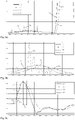
- FIG 8 To finish is in figure 8 a diagram 79 is shown below, in which the real speed 86 and the speed 87 used for control are plotted schematically. The deviations between the curves are small due to the analysis of the measured values and the corresponding consideration of a set of filter parameters.
- a Kalman filter is particularly preferably used in all of the configurations.
- the filter parameter set is determined as follows: The filter algorithm receives the (noisy) measured speed "Vr” and the (noisy) measured acceleration "Ar" of the connection units in relation to one another.
- Vr and Ar are measured by and derived from the sensor device 20, respectively.
- the speed signal and the acceleration signal can be derived from the sensor signal.
- the acceleration signal can also be determined directly via a separate acceleration sensor 47 .
- the estimated or derived speed “Vg” (reference number 87) and, if necessary, the estimated acceleration “Ag” of the relative movement of the connection units are determined with the Kalman filter.
- Vr and Ar are given in SI units and consequently in “m/s” and in “m/s2" respectively.
- variables "Q0" and "R” and “Vg” and “P” are defined.
- Vg corresponds to the estimated or derived speed 87 of the relative movement of the connection units to one another, which is used to determine the damping.
- the filter parameter set is then determined for each run and values for Q, Pp, K, Vg and P are determined.
- the parameters of the filter parameter set 82, 83 depend on the measured (noisy) values. To this end, a distinction is made as to whether the mathematical amount of the (noisy) measured acceleration "Ar" is greater than a predefined threshold value, preferably 5 in this case.
- Vp estimate speed Vg of the relative movement of the connection units to one another in the last run
- an estimated speed "Vg” (reference number 87 in 8 ) returned.
- An estimated acceleration "Ag” can also be determined and returned.
- the filter parameters and calculated values are stored as filter parameter set 83 at least until the next pass. In the next run, filter parameter set 83 becomes filter parameter set 82.
- the real speed 86 which was also recorded via additional sensors and which was subsequently determined in a complex manner after the measurement, is drawn in as a solid line. In normal driving, the real speed 86 is not available in the measurement quality for control. The real speed 86 is shown here for comparison only.
- the dashed line 88 shows the speed 88 filtered with a first set of filter parameters 82, which deviates considerably from the real speed 86 at the beginning of the measurement period shown.
- the dotted line 89 shows the course of the speed which was determined using a second set of filter parameters 83 with stronger filtering.
- the curve 89 shows a considerably smoother course than the curve 88 shown in dashed lines.
- the deviations from the course of the real speed 86 are relatively small. A slight time lag is recognizable, but it doesn't play a role with these small bumps.
- the filter parameter sets are switched over during the processing of the measured values, with the dotted curve profile 89 being used for the control up to about 14.765 seconds and with which there is a switchover from curve 89 to curve 88 from about 14.765 seconds becomes.
- the switching time 78 is shown. At this point in time, the measured speed and/or the measured acceleration has exceeded a predetermined level, so that a different set of filter parameters is selected. In all cases, more than two sets of filter parameters are also possible, for example one with less, one with medium and one with stronger filtering or smoothing.
- weighting can depend on the time interval (weighting to Example 25%, 50 and 100% for the penultimate reading, the last reading and the current value).
- Figure 9b shows the first period figure 9 enlarged, so that the deviations of the curve 88 from the real speed profile 86 are very clearly visible.
- a speed value is output for curve 88 which is four times the actual speed value that actually exists.
- a deviation in the curve 89 from the real speed 86 is very much smaller.
- Figure 9c shows the course of the stronger impact at the end of the in Figure 9a shown time period, with a good correspondence between the curves 88 and the real speed profile 86 being recognizable.
- the time offset 97 between the maximum of the real speed curve 86 and the maximum of the curve 89 is far more than 5 ms and is too large for such shocks to provide optimal damping properties.
- the invention provides a sufficiently fast and smooth and respectively adapted response behavior in all performance ranges of the damper 1 and thus an improved damper device 100
- the real-time control can be significantly improved, since the quality of the (measurement) signals used is improved, which means that a rough compression process when damping that has been noticeable in some situations up to now can be significantly reduced and practically eliminated.
Landscapes
- Engineering & Computer Science (AREA)
- General Engineering & Computer Science (AREA)
- Physics & Mathematics (AREA)
- Acoustics & Sound (AREA)
- Aviation & Aerospace Engineering (AREA)
- Mechanical Engineering (AREA)
- Vehicle Body Suspensions (AREA)
- Vibration Prevention Devices (AREA)
Claims (15)
- Procédé de commande de l'amortissement d'un mouvement relatif de deux unités de raccordement (101, 102) mobiles l'une par rapport à l'autre, entre lesquelles au moins un amortisseur (1) pilotable doté d'une soupape d'amortissement (8) à fluide magnéto-rhéologique est prévu pour amortir les mouvements relatifs, au moins un dispositif de génération de champ magnétique (11) étant associé à ladite une soupape d'amortissement (8) pour générer et commander un champ magnétique, et des ensembles de données de mesure (90, 91) étant recueillis au moins par le biais d'un mouvement relatif des unités de raccordement (101, 102) les unes par rapport aux autres, et traités à l'aide d'un dispositif de filtrage (80),caractérisé en cequ'au moins un ensemble de données déduit (92, 93) d'un ensemble de données de mesure recueilli (90, 91) est mémorisé dans le dispositif d'enregistrement (45), et que ledit ensemble de données (92, 93) déduites comprend un signal de vitesse (28) et/ou un signal d'accélération (29) pour un mouvement relatif des unités de raccordement (101, 102), et qu'au moins un ensemble de données (92, 93) mémorisées est analysé, et un ensemble de paramètres de filtrage (82, 83) est déterminé en fonction du résultat de l'analyse,et que le dispositif de commande (46) est conçu pour sélectionner un ensemble de paramètres de filtrage à filtrage plus important lorsque les signaux de vitesse et les signaux d'accélération (29) ont des valeurs réduites,et un ensemble de paramètres de filtrage à filtrage moins important lorsque les signaux de vitesse ou les signaux d'accélération (29) ont des valeurs plus élevées,et ledit ensemble de paramètres de filtrage (82, 83) sélectionné à partir de l'ensemble de données de mesure (90, 91) permettant de déduire un ensemble de données de commande (94, 95), et que le dispositif de commande (46) commande au moins partiellement le dispositif d'amortissement (100) avec l'ensemble de données de commande (94, 95).
- Procédé selon la revendication précédente, des données d'accélération (29) étant déduites de l'ensemble de données de mesure (90, 91).
- Procédé selon l'une quelconque des deux revendications précédentes, des données de vitesse (28) étant déduites des ensembles de données de mesure (90, 91).
- Procédé selon l'une quelconque des trois revendications précédentes, un ensemble de données de mesure (90, 91) étant plus fortement filtré lorsque le montant des valeurs de l'ensemble de données de mesure (90, 91) est plus bas que lorsque le montant des valeurs de l'ensemble de données de mesure (90, 91) est plus élevé.
- Procédé selon la revendication précédente, le filtrage étant plus important à des vitesses réduites qu'à des vitesses élevées.
- Procédé selon l'une quelconque des deux revendications précédentes, le filtrage étant plus important à des accélérations réduites qu'à des accélérations élevées.
- Procédé selon l'une quelconque des six revendications précédentes, plusieurs ensembles de données (90, 91) recueillis successivement l'un après l'autre étant enregistrés.
- Procédé selon l'une quelconque des sept revendications précédentes, l'ensemble des données de commande (94, 95) étant déterminé par le biais d'un lissage de plusieurs ensembles de données (92, 93).
- Procédé selon l'une quelconque des huit revendications précédentes, une importance du lissage dépendant de l'ensemble de données (90, 91) mémorisé.
- Procédé selon l'une quelconque des neuf revendications précédentes, le capteur (20) détectant des ensembles de données de mesure (90, 91) à une fréquence de mesure supérieure à 1 kHz et/ou le dispositif de commande (46) déterminant des ensembles de données de commande (90, 91) à une fréquence de commande supérieure à 1 kHz et pilotant le dispositif d'amortissement (100) au moins temporairement à au moins cette fréquence de commande.
- Procédé selon la revendication précédente, la fréquence de mesure et/ou la fréquence de commande étant supérieures à 5 kHz.
- Procédé selon l'une quelconque des deux revendications précédentes, le capteur (20) détectant des signaux de déplacement à une résolution inférieure à 100 µm ou inférieure à 50 µm.
- Procédé selon l'une quelconque des trois revendications précédentes, la fréquence de mesure et la fréquence de commande étant au moins temporairement supérieures à 8 kHz et la résolution des signaux de déplacement au moins temporairement inférieure à 5 µm.
- Procédé selon l'une quelconque des quatre revendications précédentes, la fréquence de mesure étant inférieure à 50 kHz ou inférieure à 20 kHz.
- Procédé selon l'une quelconque des revendications précédentes, une pluralité d'ensembles de paramètres de filtrage (82, 83) étant mémorisée, et un ensemble de paramètres de filtrage (82, 83) étant sélectionné en fonction dudit au moins un ensemble de données (92, 93) mémorisé.
Applications Claiming Priority (2)
| Application Number | Priority Date | Filing Date | Title |
|---|---|---|---|
| DE102015107734.5A DE102015107734A1 (de) | 2015-05-18 | 2015-05-18 | Dämpfereinrichtung und Verfahren zur Steuerung |
| PCT/EP2016/061133 WO2016184910A1 (fr) | 2015-05-18 | 2016-05-18 | Dispositif amortisseur et procédé de commande |
Publications (2)
| Publication Number | Publication Date |
|---|---|
| EP3298300A1 EP3298300A1 (fr) | 2018-03-28 |
| EP3298300B1 true EP3298300B1 (fr) | 2022-09-14 |
Family
ID=56116396
Family Applications (1)
| Application Number | Title | Priority Date | Filing Date |
|---|---|---|---|
| EP16727965.2A Active EP3298300B1 (fr) | 2015-05-18 | 2016-05-18 | Procédé de commande pour un dispositif amortisseur |
Country Status (3)
| Country | Link |
|---|---|
| EP (1) | EP3298300B1 (fr) |
| DE (1) | DE102015107734A1 (fr) |
| WO (1) | WO2016184910A1 (fr) |
Cited By (1)
| Publication number | Priority date | Publication date | Assignee | Title |
|---|---|---|---|---|
| EP4382418A1 (fr) * | 2022-12-06 | 2024-06-12 | Hyundai Motor Company | Système de train d'atterrissage avec amortisseur magnétorhéologique |
Families Citing this family (1)
| Publication number | Priority date | Publication date | Assignee | Title |
|---|---|---|---|---|
| DE102023130444A1 (de) * | 2023-11-03 | 2025-05-08 | Ktm Ag | Teleskopfedergabel mit zwei Teleskopgabelbeinen |
Citations (1)
| Publication number | Priority date | Publication date | Assignee | Title |
|---|---|---|---|---|
| EP2036746B1 (fr) * | 2007-09-17 | 2014-07-23 | S & T Daewoo Co., Ltd. | Module capteur comprenant un capteur d'accélération et un capteur de déplacement relatif, amortisseur et système de suspension électroniquement contrôlable le comprenant, et procédé pour le contrôle du mouvement du véhicule l'utilisant |
Family Cites Families (4)
| Publication number | Priority date | Publication date | Assignee | Title |
|---|---|---|---|---|
| US5971116A (en) * | 1997-03-13 | 1999-10-26 | Cannondale Corporation | Electronic suspension system for a wheeled vehicle |
| DE102012012534A1 (de) * | 2012-06-26 | 2014-01-02 | Dt Swiss Ag | Stoßdämpfer für ein Fahrrad |
| DE102012012535B4 (de) | 2012-06-26 | 2015-10-29 | Inventus Engineering Gmbh | Dämpfer und Verfahren zum Betreiben eines Dämpfers |
| DE102013021892A1 (de) * | 2013-12-23 | 2015-06-25 | Dt Swiss Ag | Fahrwerksteuerung für ein Zweirad und Verfahren |
-
2015
- 2015-05-18 DE DE102015107734.5A patent/DE102015107734A1/de not_active Ceased
-
2016
- 2016-05-18 WO PCT/EP2016/061133 patent/WO2016184910A1/fr not_active Ceased
- 2016-05-18 EP EP16727965.2A patent/EP3298300B1/fr active Active
Patent Citations (1)
| Publication number | Priority date | Publication date | Assignee | Title |
|---|---|---|---|---|
| EP2036746B1 (fr) * | 2007-09-17 | 2014-07-23 | S & T Daewoo Co., Ltd. | Module capteur comprenant un capteur d'accélération et un capteur de déplacement relatif, amortisseur et système de suspension électroniquement contrôlable le comprenant, et procédé pour le contrôle du mouvement du véhicule l'utilisant |
Cited By (2)
| Publication number | Priority date | Publication date | Assignee | Title |
|---|---|---|---|---|
| EP4382418A1 (fr) * | 2022-12-06 | 2024-06-12 | Hyundai Motor Company | Système de train d'atterrissage avec amortisseur magnétorhéologique |
| US12286218B2 (en) | 2022-12-06 | 2025-04-29 | Hyundai Motor Company | Landing gear system with magnetorheological damper |
Also Published As
| Publication number | Publication date |
|---|---|
| WO2016184910A1 (fr) | 2016-11-24 |
| DE102015107734A1 (de) | 2016-11-24 |
| EP3298300A1 (fr) | 2018-03-28 |
Similar Documents
| Publication | Publication Date | Title |
|---|---|---|
| EP3095682B1 (fr) | Commande de chassis pour un deux-roues entraine par la puissance musculaire | |
| EP2886433B1 (fr) | Commande de châssis pour un deux-roues et procédé | |
| DE3881663T2 (de) | Vorrichtung zum gemeinsamen Messen der Stellung der Radaufhängung und der Aufbaugeschwindigkeit für eine Steuerung einer Fahrzeugradaufhängung. | |
| DE102013014091B4 (de) | Fahrwerksteuerung für ein Zweirad und Verfahren | |
| EP2679859B1 (fr) | Amortisseur et procédé de fonctionnement d'un amortisseur, notamment pour une bicyclette | |
| EP2679857B1 (fr) | Amortisseur pour une bicyclette | |
| DE3937841C2 (fr) | ||
| EP2888157B1 (fr) | Système de suspension à commande électronique, methode et programme associés. | |
| DE102010055828A1 (de) | Fahrwerksteuerung für ein Fahrrad | |
| DE102010055830A1 (de) | Fahrwerksteuerung für ein Fahrrad | |
| DE4226050C2 (de) | Aufhängungssteuersystem für Kraftfahrzeuge | |
| DE69929493T2 (de) | Steuersystem für eine Fahrzeugradaufhängung und Verfahren | |
| DE4233485C2 (de) | Aufhängungssteuersystem für Kraftfahrzeuge | |
| EP0544108B1 (fr) | Système de commande d'une suspension semi-actif pour véhicules automobiles | |
| EP3109144B1 (fr) | Commande de chassis pour un deux-roues entraine par la puissance musculaire et procede | |
| DE68915442T2 (de) | Kontrollsystem für die Dämpfkraft von Stossdämpfern. | |
| DE102012012535B4 (de) | Dämpfer und Verfahren zum Betreiben eines Dämpfers | |
| DE102019104624A1 (de) | Stoßdämpfer mit Time-Of-Flight-Sensor | |
| EP3298300A1 (fr) | Dispositif amortisseur et procédé de commande | |
| DE102008052132A1 (de) | Verfahren und Vorrichtung zum Verbessern des Fahrverhaltens eines Kraftfahrzeugs | |
| DE102022124471B4 (de) | Schätzvorrichtung, Fahrzeug und Schätzverfahren | |
| WO2008052726A1 (fr) | Dispositif et procédé pour l'asservissement d'un élément de palier | |
| DE102021130656A1 (de) | Vorrichtung mit wenigstens einer Sensoreinrichtung zur Erfassung von Messdaten über eine Relativbewegung und Maßstabeinrichtung | |
| WO2016184903A1 (fr) | Dispositif amortisseur pourvu d'un amortisseur magnéto-rhéologique | |
| EP4140871B1 (fr) | Fourche pour une bicyclette et bicyclette |
Legal Events
| Date | Code | Title | Description |
|---|---|---|---|
| STAA | Information on the status of an ep patent application or granted ep patent |
Free format text: STATUS: THE INTERNATIONAL PUBLICATION HAS BEEN MADE |
|
| PUAI | Public reference made under article 153(3) epc to a published international application that has entered the european phase |
Free format text: ORIGINAL CODE: 0009012 |
|
| STAA | Information on the status of an ep patent application or granted ep patent |
Free format text: STATUS: REQUEST FOR EXAMINATION WAS MADE |
|
| 17P | Request for examination filed |
Effective date: 20171215 |
|
| AK | Designated contracting states |
Kind code of ref document: A1 Designated state(s): AL AT BE BG CH CY CZ DE DK EE ES FI FR GB GR HR HU IE IS IT LI LT LU LV MC MK MT NL NO PL PT RO RS SE SI SK SM TR |
|
| AX | Request for extension of the european patent |
Extension state: BA ME |
|
| DAV | Request for validation of the european patent (deleted) | ||
| DAX | Request for extension of the european patent (deleted) | ||
| STAA | Information on the status of an ep patent application or granted ep patent |
Free format text: STATUS: EXAMINATION IS IN PROGRESS |
|
| 17Q | First examination report despatched |
Effective date: 20190702 |
|
| GRAJ | Information related to disapproval of communication of intention to grant by the applicant or resumption of examination proceedings by the epo deleted |
Free format text: ORIGINAL CODE: EPIDOSDIGR1 |
|
| GRAP | Despatch of communication of intention to grant a patent |
Free format text: ORIGINAL CODE: EPIDOSNIGR1 |
|
| GRAJ | Information related to disapproval of communication of intention to grant by the applicant or resumption of examination proceedings by the epo deleted |
Free format text: ORIGINAL CODE: EPIDOSDIGR1 |
|
| GRAP | Despatch of communication of intention to grant a patent |
Free format text: ORIGINAL CODE: EPIDOSNIGR1 |
|
| GRAP | Despatch of communication of intention to grant a patent |
Free format text: ORIGINAL CODE: EPIDOSNIGR1 |
|
| STAA | Information on the status of an ep patent application or granted ep patent |
Free format text: STATUS: GRANT OF PATENT IS INTENDED |
|
| INTG | Intention to grant announced |
Effective date: 20220406 |
|
| GRAS | Grant fee paid |
Free format text: ORIGINAL CODE: EPIDOSNIGR3 |
|
| GRAA | (expected) grant |
Free format text: ORIGINAL CODE: 0009210 |
|
| STAA | Information on the status of an ep patent application or granted ep patent |
Free format text: STATUS: THE PATENT HAS BEEN GRANTED |
|
| AK | Designated contracting states |
Kind code of ref document: B1 Designated state(s): AL AT BE BG CH CY CZ DE DK EE ES FI FR GB GR HR HU IE IS IT LI LT LU LV MC MK MT NL NO PL PT RO RS SE SI SK SM TR |
|
| REG | Reference to a national code |
Ref country code: GB Ref legal event code: FG4D Free format text: NOT ENGLISH |
|
| REG | Reference to a national code |
Ref country code: CH Ref legal event code: EP |
|
| REG | Reference to a national code |
Ref country code: DE Ref legal event code: R096 Ref document number: 502016015276 Country of ref document: DE |
|
| REG | Reference to a national code |
Ref country code: IE Ref legal event code: FG4D Free format text: LANGUAGE OF EP DOCUMENT: GERMAN |
|
| REG | Reference to a national code |
Ref country code: AT Ref legal event code: REF Ref document number: 1518866 Country of ref document: AT Kind code of ref document: T Effective date: 20221015 |
|
| REG | Reference to a national code |
Ref country code: LT Ref legal event code: MG9D |
|
| REG | Reference to a national code |
Ref country code: NL Ref legal event code: MP Effective date: 20220914 |
|
| PG25 | Lapsed in a contracting state [announced via postgrant information from national office to epo] |
Ref country code: SE Free format text: LAPSE BECAUSE OF FAILURE TO SUBMIT A TRANSLATION OF THE DESCRIPTION OR TO PAY THE FEE WITHIN THE PRESCRIBED TIME-LIMIT Effective date: 20220914 Ref country code: RS Free format text: LAPSE BECAUSE OF FAILURE TO SUBMIT A TRANSLATION OF THE DESCRIPTION OR TO PAY THE FEE WITHIN THE PRESCRIBED TIME-LIMIT Effective date: 20220914 Ref country code: NO Free format text: LAPSE BECAUSE OF FAILURE TO SUBMIT A TRANSLATION OF THE DESCRIPTION OR TO PAY THE FEE WITHIN THE PRESCRIBED TIME-LIMIT Effective date: 20221214 Ref country code: LV Free format text: LAPSE BECAUSE OF FAILURE TO SUBMIT A TRANSLATION OF THE DESCRIPTION OR TO PAY THE FEE WITHIN THE PRESCRIBED TIME-LIMIT Effective date: 20220914 Ref country code: LT Free format text: LAPSE BECAUSE OF FAILURE TO SUBMIT A TRANSLATION OF THE DESCRIPTION OR TO PAY THE FEE WITHIN THE PRESCRIBED TIME-LIMIT Effective date: 20220914 Ref country code: FI Free format text: LAPSE BECAUSE OF FAILURE TO SUBMIT A TRANSLATION OF THE DESCRIPTION OR TO PAY THE FEE WITHIN THE PRESCRIBED TIME-LIMIT Effective date: 20220914 |
|
| PG25 | Lapsed in a contracting state [announced via postgrant information from national office to epo] |
Ref country code: HR Free format text: LAPSE BECAUSE OF FAILURE TO SUBMIT A TRANSLATION OF THE DESCRIPTION OR TO PAY THE FEE WITHIN THE PRESCRIBED TIME-LIMIT Effective date: 20220914 Ref country code: GR Free format text: LAPSE BECAUSE OF FAILURE TO SUBMIT A TRANSLATION OF THE DESCRIPTION OR TO PAY THE FEE WITHIN THE PRESCRIBED TIME-LIMIT Effective date: 20221215 |
|
| PG25 | Lapsed in a contracting state [announced via postgrant information from national office to epo] |
Ref country code: SM Free format text: LAPSE BECAUSE OF FAILURE TO SUBMIT A TRANSLATION OF THE DESCRIPTION OR TO PAY THE FEE WITHIN THE PRESCRIBED TIME-LIMIT Effective date: 20220914 Ref country code: RO Free format text: LAPSE BECAUSE OF FAILURE TO SUBMIT A TRANSLATION OF THE DESCRIPTION OR TO PAY THE FEE WITHIN THE PRESCRIBED TIME-LIMIT Effective date: 20220914 Ref country code: PT Free format text: LAPSE BECAUSE OF FAILURE TO SUBMIT A TRANSLATION OF THE DESCRIPTION OR TO PAY THE FEE WITHIN THE PRESCRIBED TIME-LIMIT Effective date: 20230116 Ref country code: ES Free format text: LAPSE BECAUSE OF FAILURE TO SUBMIT A TRANSLATION OF THE DESCRIPTION OR TO PAY THE FEE WITHIN THE PRESCRIBED TIME-LIMIT Effective date: 20220914 Ref country code: CZ Free format text: LAPSE BECAUSE OF FAILURE TO SUBMIT A TRANSLATION OF THE DESCRIPTION OR TO PAY THE FEE WITHIN THE PRESCRIBED TIME-LIMIT Effective date: 20220914 |
|
| PG25 | Lapsed in a contracting state [announced via postgrant information from national office to epo] |
Ref country code: SK Free format text: LAPSE BECAUSE OF FAILURE TO SUBMIT A TRANSLATION OF THE DESCRIPTION OR TO PAY THE FEE WITHIN THE PRESCRIBED TIME-LIMIT Effective date: 20220914 Ref country code: PL Free format text: LAPSE BECAUSE OF FAILURE TO SUBMIT A TRANSLATION OF THE DESCRIPTION OR TO PAY THE FEE WITHIN THE PRESCRIBED TIME-LIMIT Effective date: 20220914 Ref country code: IS Free format text: LAPSE BECAUSE OF FAILURE TO SUBMIT A TRANSLATION OF THE DESCRIPTION OR TO PAY THE FEE WITHIN THE PRESCRIBED TIME-LIMIT Effective date: 20230114 Ref country code: EE Free format text: LAPSE BECAUSE OF FAILURE TO SUBMIT A TRANSLATION OF THE DESCRIPTION OR TO PAY THE FEE WITHIN THE PRESCRIBED TIME-LIMIT Effective date: 20220914 |
|
| REG | Reference to a national code |
Ref country code: DE Ref legal event code: R097 Ref document number: 502016015276 Country of ref document: DE |
|
| PG25 | Lapsed in a contracting state [announced via postgrant information from national office to epo] |
Ref country code: NL Free format text: LAPSE BECAUSE OF FAILURE TO SUBMIT A TRANSLATION OF THE DESCRIPTION OR TO PAY THE FEE WITHIN THE PRESCRIBED TIME-LIMIT Effective date: 20220914 Ref country code: AL Free format text: LAPSE BECAUSE OF FAILURE TO SUBMIT A TRANSLATION OF THE DESCRIPTION OR TO PAY THE FEE WITHIN THE PRESCRIBED TIME-LIMIT Effective date: 20220914 |
|
| P01 | Opt-out of the competence of the unified patent court (upc) registered |
Effective date: 20230525 |
|
| PLBE | No opposition filed within time limit |
Free format text: ORIGINAL CODE: 0009261 |
|
| STAA | Information on the status of an ep patent application or granted ep patent |
Free format text: STATUS: NO OPPOSITION FILED WITHIN TIME LIMIT |
|
| PG25 | Lapsed in a contracting state [announced via postgrant information from national office to epo] |
Ref country code: DK Free format text: LAPSE BECAUSE OF FAILURE TO SUBMIT A TRANSLATION OF THE DESCRIPTION OR TO PAY THE FEE WITHIN THE PRESCRIBED TIME-LIMIT Effective date: 20220914 |
|
| PGFP | Annual fee paid to national office [announced via postgrant information from national office to epo] |
Ref country code: FR Payment date: 20230517 Year of fee payment: 8 Ref country code: DE Payment date: 20230620 Year of fee payment: 8 Ref country code: CH Payment date: 20230605 Year of fee payment: 8 |
|
| 26N | No opposition filed |
Effective date: 20230615 |
|
| PG25 | Lapsed in a contracting state [announced via postgrant information from national office to epo] |
Ref country code: SI Free format text: LAPSE BECAUSE OF FAILURE TO SUBMIT A TRANSLATION OF THE DESCRIPTION OR TO PAY THE FEE WITHIN THE PRESCRIBED TIME-LIMIT Effective date: 20220914 |
|
| PGFP | Annual fee paid to national office [announced via postgrant information from national office to epo] |
Ref country code: AT Payment date: 20230404 Year of fee payment: 8 |
|
| PGFP | Annual fee paid to national office [announced via postgrant information from national office to epo] |
Ref country code: GB Payment date: 20230522 Year of fee payment: 8 |
|
| PG25 | Lapsed in a contracting state [announced via postgrant information from national office to epo] |
Ref country code: MC Free format text: LAPSE BECAUSE OF FAILURE TO SUBMIT A TRANSLATION OF THE DESCRIPTION OR TO PAY THE FEE WITHIN THE PRESCRIBED TIME-LIMIT Effective date: 20220914 |
|
| REG | Reference to a national code |
Ref country code: BE Ref legal event code: MM Effective date: 20230531 |
|
| PG25 | Lapsed in a contracting state [announced via postgrant information from national office to epo] |
Ref country code: MC Free format text: LAPSE BECAUSE OF FAILURE TO SUBMIT A TRANSLATION OF THE DESCRIPTION OR TO PAY THE FEE WITHIN THE PRESCRIBED TIME-LIMIT Effective date: 20220914 Ref country code: LU Free format text: LAPSE BECAUSE OF NON-PAYMENT OF DUE FEES Effective date: 20230518 |
|
| REG | Reference to a national code |
Ref country code: IE Ref legal event code: MM4A |
|
| PG25 | Lapsed in a contracting state [announced via postgrant information from national office to epo] |
Ref country code: IE Free format text: LAPSE BECAUSE OF NON-PAYMENT OF DUE FEES Effective date: 20230518 |
|
| PG25 | Lapsed in a contracting state [announced via postgrant information from national office to epo] |
Ref country code: IE Free format text: LAPSE BECAUSE OF NON-PAYMENT OF DUE FEES Effective date: 20230518 |
|
| PG25 | Lapsed in a contracting state [announced via postgrant information from national office to epo] |
Ref country code: IT Free format text: LAPSE BECAUSE OF FAILURE TO SUBMIT A TRANSLATION OF THE DESCRIPTION OR TO PAY THE FEE WITHIN THE PRESCRIBED TIME-LIMIT Effective date: 20220914 Ref country code: BE Free format text: LAPSE BECAUSE OF NON-PAYMENT OF DUE FEES Effective date: 20230531 |
|
| PG25 | Lapsed in a contracting state [announced via postgrant information from national office to epo] |
Ref country code: BG Free format text: LAPSE BECAUSE OF FAILURE TO SUBMIT A TRANSLATION OF THE DESCRIPTION OR TO PAY THE FEE WITHIN THE PRESCRIBED TIME-LIMIT Effective date: 20220914 |
|
| PG25 | Lapsed in a contracting state [announced via postgrant information from national office to epo] |
Ref country code: BG Free format text: LAPSE BECAUSE OF FAILURE TO SUBMIT A TRANSLATION OF THE DESCRIPTION OR TO PAY THE FEE WITHIN THE PRESCRIBED TIME-LIMIT Effective date: 20220914 |
|
| REG | Reference to a national code |
Ref country code: DE Ref legal event code: R119 Ref document number: 502016015276 Country of ref document: DE |
|
| REG | Reference to a national code |
Ref country code: CH Ref legal event code: PL |
|
| REG | Reference to a national code |
Ref country code: AT Ref legal event code: MM01 Ref document number: 1518866 Country of ref document: AT Kind code of ref document: T Effective date: 20240518 |
|
| PG25 | Lapsed in a contracting state [announced via postgrant information from national office to epo] |
Ref country code: AT Free format text: LAPSE BECAUSE OF NON-PAYMENT OF DUE FEES Effective date: 20240518 |
|
| GBPC | Gb: european patent ceased through non-payment of renewal fee |
Effective date: 20240518 |
|
| PG25 | Lapsed in a contracting state [announced via postgrant information from national office to epo] |
Ref country code: AT Free format text: LAPSE BECAUSE OF NON-PAYMENT OF DUE FEES Effective date: 20240518 Ref country code: CH Free format text: LAPSE BECAUSE OF NON-PAYMENT OF DUE FEES Effective date: 20240531 |
|
| PG25 | Lapsed in a contracting state [announced via postgrant information from national office to epo] |
Ref country code: DE Free format text: LAPSE BECAUSE OF NON-PAYMENT OF DUE FEES Effective date: 20241203 |
|
| PG25 | Lapsed in a contracting state [announced via postgrant information from national office to epo] |
Ref country code: FR Free format text: LAPSE BECAUSE OF NON-PAYMENT OF DUE FEES Effective date: 20240531 |
|
| PG25 | Lapsed in a contracting state [announced via postgrant information from national office to epo] |
Ref country code: GB Free format text: LAPSE BECAUSE OF NON-PAYMENT OF DUE FEES Effective date: 20240518 |
|
| PG25 | Lapsed in a contracting state [announced via postgrant information from national office to epo] |
Ref country code: CY Free format text: LAPSE BECAUSE OF FAILURE TO SUBMIT A TRANSLATION OF THE DESCRIPTION OR TO PAY THE FEE WITHIN THE PRESCRIBED TIME-LIMIT; INVALID AB INITIO Effective date: 20160518 |
|
| PG25 | Lapsed in a contracting state [announced via postgrant information from national office to epo] |
Ref country code: HU Free format text: LAPSE BECAUSE OF FAILURE TO SUBMIT A TRANSLATION OF THE DESCRIPTION OR TO PAY THE FEE WITHIN THE PRESCRIBED TIME-LIMIT; INVALID AB INITIO Effective date: 20160518 |
|
| PG25 | Lapsed in a contracting state [announced via postgrant information from national office to epo] |
Ref country code: TR Free format text: LAPSE BECAUSE OF FAILURE TO SUBMIT A TRANSLATION OF THE DESCRIPTION OR TO PAY THE FEE WITHIN THE PRESCRIBED TIME-LIMIT Effective date: 20220914 |