EP3298436B1 - Appareil de mesure radiométrique - Google Patents
Appareil de mesure radiométrique Download PDFInfo
- Publication number
- EP3298436B1 EP3298436B1 EP16725100.8A EP16725100A EP3298436B1 EP 3298436 B1 EP3298436 B1 EP 3298436B1 EP 16725100 A EP16725100 A EP 16725100A EP 3298436 B1 EP3298436 B1 EP 3298436B1
- Authority
- EP
- European Patent Office
- Prior art keywords
- measuring device
- interface
- radiometric measuring
- designed
- current
- Prior art date
- Legal status (The legal status is an assumption and is not a legal conclusion. Google has not performed a legal analysis and makes no representation as to the accuracy of the status listed.)
- Active
Links
Images

Classifications
-
- G—PHYSICS
- G01—MEASURING; TESTING
- G01T—MEASUREMENT OF NUCLEAR OR X-RADIATION
- G01T1/00—Measuring X-radiation, gamma radiation, corpuscular radiation, or cosmic radiation
- G01T1/16—Measuring radiation intensity
- G01T1/20—Measuring radiation intensity with scintillation detectors
- G01T1/2018—Scintillation-photodiode combinations
-
- G—PHYSICS
- G01—MEASURING; TESTING
- G01T—MEASUREMENT OF NUCLEAR OR X-RADIATION
- G01T1/00—Measuring X-radiation, gamma radiation, corpuscular radiation, or cosmic radiation
- G01T1/16—Measuring radiation intensity
- G01T1/17—Circuit arrangements not adapted to a particular type of detector
- G01T1/175—Power supply circuits
Definitions
- the invention relates to a radiometric measuring device.
- radiometric measuring devices for example for level or density measurement, which signal their measured or process values via a current interface or a current output (4-20 mA), require an energy supply that is separate from the current interface or the current output due to their comparatively high energy consumption is.
- the DE 10 2007 053 860 A1 shows a radiometric measuring device that has a pair of lines, the pair of lines providing power to the measuring device and transmitting a measurement signal.
- the DE 10 2013 005 226 A1 shows a measuring device with an interface for transmitting energy and / or signals.
- the WO 2015/090765 A1 shows a radiometric measuring device for performing measurements in hazardous areas.
- the EP 1 860 513 A2 shows a circuit for the secure transmission of an analog signal value with a current interface.
- the invention is based on the object of providing a radiometric measuring device which can be used as flexibly as possible.
- the invention achieves this object by means of a radiometric measuring device according to claim 1.
- the radiometric measuring device can, for example, be a radiometric scintillation detector for detecting gamma or neutron radiation for level or density measurement in the process industry.
- the radiometric meter includes one or more conventional scintillators. In this respect, reference is also made to the relevant specialist literature.
- the radiometric measuring device further has one or more semiconductor photodiodes, the semiconductor photodiode (s) being optically coupled to the scintillator or scintillators.
- the radiometric measuring device also has a signal evaluation unit, for example in the form of a microprocessor and / or signal processor.
- the signal evaluation unit is electrically coupled to the at least one semiconductor photodiode.
- the signal evaluation unit is designed to determine a measured variable as a function of a measurement signal, for example in the form of measurement pulses, which is generated by the at least one semiconductor photodiode, in particular continuously and without measurement pauses.
- a count rate of pulses can be determined which are generated by means of the semiconductor photodiode, a fill level, a density, etc. being calculated based on the count rate.
- the radiometric measuring device is designed to measure continuously and without measuring pauses.
- the measured variable can be, for example, a level, the density and / or a mass flow.
- the measured variable is preferably determined directly in the radiometric measuring device itself, i.e. it is not only intermediate measured variables which are then used in the receiver to determine the measured variable.
- the radiometric measuring device also has an electrical interface, the radiometric measuring device being able to be coupled by means of or via the interface to at least one receiver for unidirectional or bidirectional data exchange.
- the measured variable or its value can be transmitted to the receiver via the interface.
- electrical interface energy is available on the interface, which is fed into the interface by the receiver, for example, by impressing a voltage or a current, for example.
- the radiometric measuring device is designed to be supplied with electrical energy exclusively via its interface.
- the radiometric measuring device is supplied with electrical (operating) energy exclusively via the interface.
- the radiometric measuring device can have a voltage supply device, the voltage supply device being electrically coupled to the interface and designed to supply one or more supply voltages for the radiometric measuring device exclusively from a voltage present at the interface and / or exclusively from a current flowing through the interface produce.
- the supply voltage or the voltages / currents derived from the supply voltage can serve to supply all electrical components of the radiometric measuring device.
- the voltage supply device can have a voltage converter, for example in the form of a DC / DC converter, for level conversion.
- the voltage converter can have a step-up and / or a step-down section.
- the voltage generated by the voltage converter can serve, for example, as a supply voltage for a semiconductor sensor, for example in the form of a SiPM.
- the voltage supply device can also have several DC / DC converters or voltage converters for level conversion, for example one voltage converter for generating voltages greater than 20V and another voltage converter for generating voltages less than 6V.
- the interface can be an analog current interface, for example a so-called 4-20 mA current loop. This can e.g. be designed according to the Namur standards NE006 and NE043.
- the interface can also be a digital current interface or a mixed analog / digital interface (HART communication).
- the interface can be a two-wire interface.
- the radiometric measuring device can contain the following interfaces for process connection, for example: Modbus interface, Profibus interface, HART interface, FOUN-DATION Fieldbus interface, Ethernet interface.
- the at least one semiconductor photodiode can be a semiconductor photodiode with internal amplification, for example an avalanche photodiode (APD) or a silicon photomultiplier (SiPM).
- APD avalanche photodiode
- SiPM silicon photomultiplier
- the invention relates to a radiometric measuring device, for example in the form of a radiometric scintillation detector for the detection of gamma or neutron radiation for level or density measurement in the process industry.
- the radiometric measuring device comprises a scintillator, one or more semiconductor photodiodes with internal amplification (APD or SiPM) and a signal processing and transmission unit. Due to the properties of the semiconductor diodes, the radiometric measuring device can be designed to be very energy-efficient. It is thus possible to feed the radiometric measuring device exclusively via its interface, for example with the electrical power available in a 4-20 mA current loop.
- the radiometric measuring device can therefore also be used for applications in hazardous areas must be designed with intrinsically safe type of protection and used in all zones including zone 0.
- the radiometric measuring device can have a decay compensation, with which the decrease in activity due to the decay of a radioactive nuclide used for the measurement can be compensated.
- the radiometric measuring device can have components that enable the date and time to be determined, for example a real-time clock or a radio receiver that is designed, for example, to receive GPS signals or as a receiver to receive DCF77, MSF, JJY or WWVB signals.
- the radiometric measuring device can have a non-volatile data memory for storing calibration data (application calibration data or electrical component calibration data) or production data.
- the radiometric measuring device can have one or more semiconductor sensors which are suitable or suitable for the direct detection of ionizing radiation or for the detection of secondary radiation (for example scintillation light) which has been converted by means of one or more scintillators.
- semiconductor sensors which are suitable or suitable for the direct detection of ionizing radiation or for the detection of secondary radiation (for example scintillation light) which has been converted by means of one or more scintillators.
- the radiometric measuring device can have a control device, which can contain one or more function blocks that generate one or more control signals.
- a function block can, for example, generate a control signal as a function of the temperature or characteristic properties of the spectrum, which control signal can be used to stabilize the measuring device.
- Another function block can generate a second control signal for controlling the functional unit that transmits process values.
- the functional unit transmitting process values can transmit its information analog or digital to the receiver (for example feed separator, PLC or process control system).
- the radiometric measuring device can have an Ex i barrier to limit current, voltage and power.
- the Ex i barrier has the property of blocking electrical energy contained or stored in the measuring device in the event of a fault or converting it into heat, so that this is not passed on to the connection terminals of the measuring device and can cause an ignitable mixture to explode.
- the radiometric measuring device In normal operation or in measuring operation, during which it determines the measured variable, the radiometric measuring device is supplied with electrical energy exclusively via its interface.
- the radiometric measuring device can be designed with type of protection Ex i or combine this type of protection with other types of protection (e.g. Ex m), i.e. the radiometric measuring device can be of intrinsically safe type of protection or a combination of intrinsically safe and encapsulated ignition protection type or intrinsically safe and pressure-resistant.
- the interface is a current interface, the radiometric measuring device being designed to encode and / or transmit the measured variable by means of the current consumption of the radiometric measuring device.
- the radiometric measuring device has at least one electrical energy store, wherein the at least one electrical energy store can be (re) charged by means of a charging current.
- the electrical energy store can for example be a rechargeable energy store of a real-time clock of the measuring device.
- the radiometric measuring device also has a charging current regulator which is designed to set the charging current as a function of the measured variable.
- the radiometric measuring device can have a real time clock (RTC, or real-time clock), for example in order to determine the date and time required for a decay compensation.
- RTC real time clock
- the energy store is designed to supply the real-time clock with electrical energy when (as soon as) no energy is made available via the interface.
- the energy store serves as a buffer store for the real time clock.
- the radiometric measuring device has at least one adjustable ballast resistor (burden), by means of which the current consumption of the radiometric measuring device can be controlled.
- the charging current regulator is designed to set a resistance value of the at least one ballast resistor as a function of the measured variable, ie the resistance value can be as The manipulated variable of the charge current controller is used.
- the charging current regulator is designed to set the resistance value of the at least one ballast resistor as a function of the measured variable in such a way that a current through the at least one ballast resistor is minimal and the charging current is maximal as long as there is still a storage or charging capacity of the electrical energy store is not exhausted. If the storage or charging capacity of the electrical energy store is exhausted, the charging current can be set to zero and excess electrical energy can be converted into thermal energy in the at least one ballast resistor.
- the signal evaluation unit can be designed to check the determination of the measured variable with regard to possible errors, the radiometric measuring device being designed to in the event of a fault, deactivate those assemblies of the radiometric measuring device that are intended for determining the measured variable.
- Fig. 1 shows schematically a radiometric measuring system with a radiometric measuring device 1, which is coupled to a receiver 6 via its 4-20 mA current interface 5.
- the radiometric measuring device 1 conventionally has a scintillator 2.
- a semiconductor photodiode 3 in the form of a SiPM is also provided, the SiPM 3 being optically coupled to the scintillator 2.
- the SiPM 3 converts the light pulses generated in the scintillator into electrical current pulses.
- a signal evaluation unit 4 is electrically coupled to the SiPM 3.
- the signal evaluation unit 4 is designed to continuously determine a measured variable, for example in the form of a fill level, as a function of a measurement signal that is generated by the SiPM 3.
- the signal evaluation unit 4 can further regulate, for example, a bias voltage of the SiPM 3, monitor proper functioning of the SiPM 3, etc.
- the radiometric measuring device 1 is coupled to the receiver 6 for data exchange by means of its interface 5, ie the measured values or measured variables continuously and uninterruptedly determined by the radiometric measuring device 1 are continuously and uninterruptedly transmitted to the receiver 6 via the interface 5.
- the interface 5 ie the measured values or measured variables continuously and uninterruptedly determined by the radiometric measuring device 1 are continuously and uninterruptedly transmitted to the receiver 6 via the interface 5.
- the receiver 6 conventionally provides electrical interface energy by means of an impressed current or an impressed voltage. In this respect, too, reference is made to the relevant specialist literature on the 4-20 mA interface.
- the radiometric measuring device 1 has a voltage supply device 7 which is electrically coupled to the interface 5.
- the radiometric measuring device 1 is supplied with voltage exclusively by means of the voltage supply device 7.
- the voltage supply device 7 draws a required portion of the available interface energy from the interface 5 and provides this portion as operating energy in the form of one or more supply voltages. No other energy sources are available to the voltage supply device 7, i. the radiometric measuring device 1 is supplied with energy exclusively via its interface 5.
- the voltage supply device 7 supplies the signal evaluation unit 4 and the SiPM 3 with the voltages / currents necessary for their operation.
- the voltage supply device 7 can have one or more DC / DC converters for voltage conversion or level adjustment, for example in the form of a boost converter, which generates a voltage with a suitable level from a voltage present at the interface 5 / en.
- the interface 5 can have a so-called barrier, which may be necessary for reasons of explosion protection.
- the barrier separates any internal energy storage from the intrinsically safe loop circuit.
- the barrier can be omitted with non-intrinsically safe devices.
- the interface 5 can have a so-called process interface.
- the process interface is used to convert the determined measured value, for example pulses per second, or the determined measured variable, for example level, density and / or mass flow, into electrical information to be transmitted to the receiver, for example 4-20 mA loop current or bus data such as Profibus or similar
- the interface 5 can also have a modem.
- the modem can be used, for example, to transmit communication data (e.g. Bell 202 for HART communication).
- An optional energy store can be provided to buffer the energy taken from the interface.
- the interface 5 can also be a field bus interface, for example a Profibus interface.
- the essential advantages of the radiometric measuring device 1 according to the invention lie in the possible use up to Ex zone 0 and / or in the installation as a two-wire device. A user only needs two lines to the field device, since there is no need to supply a separate supply voltage for the radiometric measuring device 1.
- the armored cable required for this in the Ex area can also be omitted.
- the complex, flameproof encapsulation of the radiometric measuring device 1 can be omitted. This results in a considerable cost advantage.
- Fig. 2 shows schematically a radiometric measuring device 1 'according to a further embodiment.
- Fig. 2 only part of the radiometric measuring device 1 'is shown.
- the components 2, 3, 4, 5 and 7 are of course also present, although not shown for reasons of clarity. To that extent, refer to the statements Fig. 1 referenced.
- the radiometric measuring device 1 ' has an electrical energy store 8, which can be charged by means of a charging current I_Lade.
- the radiometric measuring device 1 ′ furthermore has a charging current regulator 9 which is designed to set the charging current I_Lade as a function of the measured variable to be transmitted.
- the radiometric measuring device 1 ' has two ballast resistors 10, 11 connected in parallel, by means of which the current consumption I_Loop of the radiometric measuring device 1' can be controlled or influenced.
- the second ballast resistor 11 has a high resistance in the fault-free case and only serves to provide a second switch-off path under certain fault conditions, which can cause a fault current to produce a safe state. In this respect, it also applies to the EP 1 860 513 A2 referenced.
- the second shutdown path only has to be active at 24 mA loop current, all circuit parts of the second shutdown path are only activated when the second shutdown path is required. This leads to an energy saving.
- the charging current regulator 9 is designed to set a resistance value of the first ballast resistor 10 as a function of the measured variable to be transmitted such that a current through the first ballast resistor 10 is minimal and the charging current I_Lade is maximal.
- a shunt or measuring resistor 12 is used to measure the current consumption I_Loop of the radiometric measuring device 1 ', the current measured in this way being evaluated in the current regulator 9 for regulation.
- the current I_Loop represents the current measured value of the measured variable.
- the current I_Loop must not fall below a specified minimum value, since the device 1 'is supplied with this current. If, for the transmission or signaling of a value of a measured variable, a current is required that is greater than this minimum value (operating current required by the measuring device 1 'itself), this is compensated for by means of the ballast resistor 10, which can be used as an active component e.g. can be designed in the form of a bipolar transistor and / or a field effect transistor, whereby power loss is generated that is not available to supply the measuring device 1 '.
- the current through the ballast resistor 10 is now reduced to a minimum required for proper functioning, for example to 0.8 mA for HART communication.
- the excess current is fed to the electrical energy store 8 as charging current I_Lade. If the energy store 8 can no longer absorb the energy, the ballast resistor 10 lowers the required current.
- the electrical energy store 8 can, for example, be an energy store of a real-time clock.
- excess energy is available in the measuring device 1 ', it can be used, for example, for charging the energy store 8 used for buffering the real-time clock.
- the radiometric measuring device 1 has an electrical display element (not shown here), for example in the form of a display, for a user and optionally additionally an input element (not shown here), for example in the form of a keyboard, for example with three, four, five, six or more buttons for this.
- the display or a backlight can be activated continuously.
- the display or its background lighting can be deactivated for most of the time and activated for a certain period of time by pressing a key. Basically it can be excess Energy in the measuring device 1 'are buffered so that a background lighting of the display or the display itself can be activated in the event of user interaction.
- the signal evaluation unit 4 has a diagnostic device which is designed to check the determination of the measured variable with regard to possible errors, the radiometric measuring device being designed to assign such assemblies, in the present example the semiconductor photodiode 3, of the radiometric measuring device in the event of a fault that are intended for determining the measured variable.
- the measuring device should generate a loop current I_Loop of ⁇ 3.6 mA. This reduces the energy available to the measuring device further. This may not be possible due to the internal energy consumption of the measuring device.
- the measuring device is therefore designed to switch off individual energy consumers or functional assemblies of the measuring device 1, 1 '.
- the measured variable is no longer determined in the event of an error, since it is questionable whether the measured variable can still be correctly determined due to the error.
- This makes it possible to deactivate those assemblies of the radiometric measuring device that are provided for determining the measured variable.
- This can be, for example, the semiconductor photodiode 2 or its voltage supply, operational amplifiers, comparators including an analog voltage supply, which are to be switched off. This significantly reduces the energy consumption of the measuring device, which means that a loop current I_Loop of ⁇ 3.6 mA can be signaled.
- FIG. 2 The embodiment shown in FIG Fig. 1 shown, so that in this regard, the designs and features of the in Fig. 1 Reference is made to the embodiment shown in order to avoid repetition.
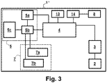
- Fig. 3 shows schematically a radiometric measuring device 1 ′′ according to a further embodiment.
- the interface 5 has a modem 5a, a process interface 5b and an Ex i barrier 5c.
- the signal evaluation unit 4 is also assigned a non-volatile data memory 13 which is used to store calibration data (application calibration data or electrical component calibration data) or production data.
- a real time clock 14 is also assigned to the signal evaluation unit 4, the electrical energy store 8 being designed to supply the real time clock 14 with electrical energy when no electrical energy is made available via the interface 5.
- the interface 5 can be like that in Fig. 2
- the signal evaluation unit 4 carries out a decay compensation, the real time clock 14 serving, inter alia, to determine a date and time required for a decay compensation.
- FIG. 3 The embodiment shown in FIG Fig. 1 or. Fig. 2 shown, so that in this regard, the designs and features of the Figures 1 Reference is made to the embodiment shown and to avoid repetition.
Landscapes
- Physics & Mathematics (AREA)
- Health & Medical Sciences (AREA)
- Life Sciences & Earth Sciences (AREA)
- General Physics & Mathematics (AREA)
- High Energy & Nuclear Physics (AREA)
- Molecular Biology (AREA)
- Spectroscopy & Molecular Physics (AREA)
- Measurement Of Radiation (AREA)
- Arrangements For Transmission Of Measured Signals (AREA)
Claims (10)
- Appareil de mesure radiométrique (1, 1', 1"), comprenant :- un scintillateur (2),- au moins une photodiode à semiconducteur (3), l'au moins une photodiode à semiconducteur (3) étant couplée optiquement avec le scintillateur (2),- une unité d'interprétation de signal (4), qui est connectée électriquement à l'au moins une photodiode à semiconducteur (3) et qui est configurée pour déterminer une grandeur mesurée en fonction d'un signal de mesure qui est généré au moyen de l'au moins une photodiode à semiconducteur (3),- une interface (5), l'appareil de mesure radiométrique (1, 1', 1") pouvant être connecté au moyen de l'interface (5) à au moins un récepteur (6),- l'appareil de mesure radiométrique (1, 1', 1") étant configuré pour être alimenté en énergie exclusivement par le biais de son interface (5),- l'interface (5) étant une interface de courant, l'appareil de mesure radiométrique (1, 1', 1") étant configuré pour coder la grandeur mesurée au moyen d'une consommation de courant par l'appareil de mesure radiométrique (1, 1', 1"),- au moins un accumulateur d'énergie électrique (8), qui peut être chargé au moyen d'un courant de charge (I_Lade), et- un régulateur de courant de charge (9), qui est configuré pour régler le courant de charge (I_Lade) en fonction de la grandeur mesurée, et- au moins une résistance ballast (10, 11) réglable, au moyen de laquelle peut être commandée la consommation de courant (I_Loop) de l'appareil de mesure radiométrique (1, 1', 1"),- le régulateur de courant de charge (9) étant configuré pour régler la valeur de résistance de l'au moins une résistance ballast (10, 11) en fonction de la grandeur de mesure de telle sorte qu'un courant à travers l'au moins une résistance ballast (10, 11) est minimal et le courant de charge (I_Lade) maximal.
- Appareil de mesure radiométrique (1, 1', 1") selon la revendication 1, caractérisé en ce que- l'appareil de mesure radiométrique (1, 1', 1") possède un dispositif d'alimentation en tension électrique (7), le dispositif d'alimentation en tension électrique (7) étant connecté électriquement à l'interface (5) et étant configuré pour générer une tension d'alimentation pour l'appareil de mesure radiométrique (1, 1', 1") à partir d'une tension présente au niveau de l'interface (5) et/ou à partir d'un courant qui s'écoule par le biais de l'interface (5).
- Appareil de mesure radiométrique (1, 1', 1") selon la revendication 2, caractérisé en ce que- le dispositif d'alimentation en tension électrique (7) possède un convertisseur de tension.
- Appareil de mesure radiométrique (1, 1', 1") selon l'une des revendications 1 à 3, caractérisé en ce que- l'interface (5) est une interface analogique ou une interface numérique.
- Appareil de mesure radiométrique (1, 1', 1") selon l'une des revendications précédentes, caractérisé en ce que- l'interface (5) est une interface à deux conducteurs.
- Appareil de mesure radiométrique (1, 1', 1") selon l'une des revendications précédentes, caractérisé en ce que- l'au moins une photodiode à semiconducteur (3) est une photodiode à semiconducteur avec amplification interne.
- Appareil de mesure radiométrique (1, 1', 1") selon l'une des revendications précédentes, caractérisé en ce que- l'au moins une photodiode à semiconducteur (3) est une photodiode à avalanche ou un photomultiplicateur au silicium.
- Appareil de mesure radiométrique (1, 1', 1") selon l'une des revendications précédentes, caractérisé en ce que l'appareil de mesure radiométrique (1, 1', 1") possède :- une horloge à temps réel (14),- l'accumulateur d'énergie électrique (8) étant configuré pour alimenter l'horloge à temps réel (14) en énergie électrique lorsqu'aucune énergie électrique n'est mise à disposition par le biais de l'interface (5).
- Appareil de mesure radiométrique (1, 1', 1") selon l'une des revendications précédentes, caractérisé en ce que- l'unité d'interprétation de signal (4) est configurée pour vérifier la détermination de la grandeur mesurée en vue d'y détecter d'éventuelles erreurs, l'appareil de mesure radiométrique (1, 1', 1") étant configuré pour, en cas d'erreur, désactiver les sous-ensembles (3) de l'appareil de mesure radiométrique (1, 1', 1") qui sont prévus pour la détermination de la grandeur mesurée.
- Appareil de mesure radiométrique (1, 1', 1") selon l'une des revendications précédentes, caractérisé en ce que- l'unité d'interprétation de signal (4) est configurée pour déterminer la grandeur mesurée continuellement et sans pauses de mesure.
Applications Claiming Priority (2)
| Application Number | Priority Date | Filing Date | Title |
|---|---|---|---|
| DE102015209366.2A DE102015209366A1 (de) | 2015-05-21 | 2015-05-21 | Radiometrisches Messgerät |
| PCT/EP2016/061469 WO2016185028A1 (fr) | 2015-05-21 | 2016-05-20 | Appareil de mesure radiométrique |
Publications (2)
| Publication Number | Publication Date |
|---|---|
| EP3298436A1 EP3298436A1 (fr) | 2018-03-28 |
| EP3298436B1 true EP3298436B1 (fr) | 2020-12-30 |
Family
ID=56081469
Family Applications (1)
| Application Number | Title | Priority Date | Filing Date |
|---|---|---|---|
| EP16725100.8A Active EP3298436B1 (fr) | 2015-05-21 | 2016-05-20 | Appareil de mesure radiométrique |
Country Status (4)
| Country | Link |
|---|---|
| US (1) | US10132940B2 (fr) |
| EP (1) | EP3298436B1 (fr) |
| DE (1) | DE102015209366A1 (fr) |
| WO (1) | WO2016185028A1 (fr) |
Families Citing this family (6)
| Publication number | Priority date | Publication date | Assignee | Title |
|---|---|---|---|---|
| DE102016122048A1 (de) * | 2016-11-16 | 2018-05-17 | Endress+Hauser SE+Co. KG | Verfahren zur Bestimmung einer Restbetriebs-Zeitdauer einer Detektor-Einheit |
| EP3349047B1 (fr) * | 2017-01-13 | 2020-12-23 | Berthold Technologies GmbH & Co. KG | Système modulaire pour un appareil de mesure radiométrique |
| DE102017205758A1 (de) * | 2017-04-04 | 2018-10-04 | Vega Grieshaber Kg | Eigensicheres radiometrisches Messgerät im Kunststoffgehäuse |
| DE102017110633B3 (de) * | 2017-05-16 | 2018-11-15 | Krohne Messtechnik Gmbh | Anzeigegerät für die Prozessautomation |
| EP4066021B1 (fr) * | 2019-11-27 | 2025-09-03 | Thermo Fisher Scientific Messtechnik GmbH | Generateur de polarisation connecte au sipm |
| DE102023206449B3 (de) | 2023-07-06 | 2024-10-10 | Vega Grieshaber Kg | Erzeugung einer Hochspannung zur Versorgung eines Photomultipliers |
Citations (1)
| Publication number | Priority date | Publication date | Assignee | Title |
|---|---|---|---|---|
| KR20140041041A (ko) * | 2012-09-27 | 2014-04-04 | 주식회사 레이언스 | 엑스레이 감지장치 |
Family Cites Families (7)
| Publication number | Priority date | Publication date | Assignee | Title |
|---|---|---|---|---|
| DE10043629A1 (de) * | 2000-09-01 | 2002-03-14 | Endress Hauser Gmbh Co | Vorrichtung zur Bestimmung und/oder Überwachung der Dichte und/oder des Füllstands eines Füllguts in einem Behälter |
| DE102006024311A1 (de) | 2006-05-24 | 2007-11-29 | Berthold Technologies Gmbh & Co. Kg | Schaltung zur Übermittlung eines analogen Signalwertes |
| DE102007053860A1 (de) * | 2007-11-09 | 2009-05-14 | Endress + Hauser Gmbh + Co. Kg | Radiometrisches Messgerät |
| EP2187186A1 (fr) * | 2008-11-17 | 2010-05-19 | VEGA Grieshaber KG | Mesure du niveau de remplissage et d'étanchéité radiométrique |
| DE102013005226B4 (de) * | 2013-03-27 | 2017-11-16 | Krohne Messtechnik Gmbh | Messgerät |
| DE102013114617A1 (de) | 2013-12-20 | 2015-06-25 | Endress + Hauser Gmbh + Co. Kg | Radiometrisches Messgerät zur Ausführung von Messungen in explosionsgefährdeten Bereichen |
| CN107110980B (zh) * | 2014-12-23 | 2020-05-05 | 皇家飞利浦有限公司 | 低成本的数字式pet设计 |
-
2015
- 2015-05-21 DE DE102015209366.2A patent/DE102015209366A1/de active Pending
-
2016
- 2016-05-20 WO PCT/EP2016/061469 patent/WO2016185028A1/fr not_active Ceased
- 2016-05-20 EP EP16725100.8A patent/EP3298436B1/fr active Active
- 2016-05-20 US US15/566,736 patent/US10132940B2/en active Active
Patent Citations (1)
| Publication number | Priority date | Publication date | Assignee | Title |
|---|---|---|---|---|
| KR20140041041A (ko) * | 2012-09-27 | 2014-04-04 | 주식회사 레이언스 | 엑스레이 감지장치 |
Also Published As
| Publication number | Publication date |
|---|---|
| US10132940B2 (en) | 2018-11-20 |
| US20180120454A1 (en) | 2018-05-03 |
| DE102015209366A1 (de) | 2016-11-24 |
| EP3298436A1 (fr) | 2018-03-28 |
| WO2016185028A1 (fr) | 2016-11-24 |
Similar Documents
| Publication | Publication Date | Title |
|---|---|---|
| EP3298436B1 (fr) | Appareil de mesure radiométrique | |
| EP2208031B1 (fr) | Appareil de mesure radiométrique à deux fils pour la mesure du niveau de remplissage | |
| EP2936686B1 (fr) | Circuit convertisseur avec interface de courant et appareil de mesure équipé d'un tel circuit convertisseur | |
| EP2246984B1 (fr) | Appareil de diagnostic destinée au contrôle d'un appareil de conversion analogique-numérique | |
| WO2005078397A1 (fr) | Appareil radiometrique de mesure de niveau de remplissage | |
| EP2445744A2 (fr) | Dispositif de détection implanté dans une station de charge et détectant le volume d'énergie livré à un véhicule électrique, et procédé correspondant | |
| DE102014101945A1 (de) | Messumformer mit Überwachungsfunktion | |
| EP3036589A1 (fr) | Appareil électronique protégé contre des manipulations frauduleuses | |
| EP3948166B1 (fr) | Module supplémentaire pour un dispositif de terrain | |
| EP3349047B1 (fr) | Système modulaire pour un appareil de mesure radiométrique | |
| EP1933116A2 (fr) | Appareil de terrain pouvant fonctionner sur batterie destiné à l'instrumentation de processus | |
| DE102016122048A1 (de) | Verfahren zur Bestimmung einer Restbetriebs-Zeitdauer einer Detektor-Einheit | |
| DE102017205758A1 (de) | Eigensicheres radiometrisches Messgerät im Kunststoffgehäuse | |
| EP1278073A1 (fr) | Dispositif de mesure d'un courant électrique qui circule dans au moins un conducteur électrique et méthode de correction d'erreurs dans ledit dispositif | |
| DE102015100166A1 (de) | Methode zur aufeinanderfolgenden Anordnung von radiometrischen Messgeräten | |
| DE102007008731A1 (de) | Wechselrichter mit Zeitzählfunktion | |
| EP3270123B1 (fr) | Appareil de mesure radiometrique pour fonctionnement en deux fils | |
| DE102014102021A1 (de) | Feldgerät der Automatisierungstechnik | |
| DE102010033164A1 (de) | Elektronischer Haushaltszähler | |
| DE102016117356A1 (de) | Spektroskopisches Online-Messsystem zur Messung von Gammastrahlung mit einem erweiterten Messbereich | |
| DE102013216197A1 (de) | Verfahren zum Betreiben eines radiometrischen Messsystems und radiometrisches Messsystem | |
| DE102011012956A1 (de) | Verbrauchsmittelzählersystem | |
| AT521939A2 (de) | Verfahren und Messvorrichtung zum Ermitteln einer Latenzzeit | |
| WO1998018243A1 (fr) | Transmission de donnees optique par modulation d'impulsions en position | |
| WO2012079947A1 (fr) | Appareil de mesure radiométrique |
Legal Events
| Date | Code | Title | Description |
|---|---|---|---|
| STAA | Information on the status of an ep patent application or granted ep patent |
Free format text: STATUS: THE INTERNATIONAL PUBLICATION HAS BEEN MADE |
|
| PUAI | Public reference made under article 153(3) epc to a published international application that has entered the european phase |
Free format text: ORIGINAL CODE: 0009012 |
|
| STAA | Information on the status of an ep patent application or granted ep patent |
Free format text: STATUS: REQUEST FOR EXAMINATION WAS MADE |
|
| 17P | Request for examination filed |
Effective date: 20171218 |
|
| AK | Designated contracting states |
Kind code of ref document: A1 Designated state(s): AL AT BE BG CH CY CZ DE DK EE ES FI FR GB GR HR HU IE IS IT LI LT LU LV MC MK MT NL NO PL PT RO RS SE SI SK SM TR |
|
| AX | Request for extension of the european patent |
Extension state: BA ME |
|
| RIN1 | Information on inventor provided before grant (corrected) |
Inventor name: MUELLER, STEFFEN Inventor name: DAIBENZEIHER, TOBIAS Inventor name: FREIBURGER, EWALD |
|
| DAV | Request for validation of the european patent (deleted) | ||
| DAX | Request for extension of the european patent (deleted) | ||
| GRAP | Despatch of communication of intention to grant a patent |
Free format text: ORIGINAL CODE: EPIDOSNIGR1 |
|
| STAA | Information on the status of an ep patent application or granted ep patent |
Free format text: STATUS: GRANT OF PATENT IS INTENDED |
|
| INTG | Intention to grant announced |
Effective date: 20200714 |
|
| GRAS | Grant fee paid |
Free format text: ORIGINAL CODE: EPIDOSNIGR3 |
|
| GRAA | (expected) grant |
Free format text: ORIGINAL CODE: 0009210 |
|
| STAA | Information on the status of an ep patent application or granted ep patent |
Free format text: STATUS: THE PATENT HAS BEEN GRANTED |
|
| AK | Designated contracting states |
Kind code of ref document: B1 Designated state(s): AL AT BE BG CH CY CZ DE DK EE ES FI FR GB GR HR HU IE IS IT LI LT LU LV MC MK MT NL NO PL PT RO RS SE SI SK SM TR |
|
| REG | Reference to a national code |
Ref country code: GB Ref legal event code: FG4D Free format text: NOT ENGLISH |
|
| REG | Reference to a national code |
Ref country code: AT Ref legal event code: REF Ref document number: 1350473 Country of ref document: AT Kind code of ref document: T Effective date: 20210115 |
|
| REG | Reference to a national code |
Ref country code: DE Ref legal event code: R096 Ref document number: 502016012080 Country of ref document: DE |
|
| REG | Reference to a national code |
Ref country code: IE Ref legal event code: FG4D Free format text: LANGUAGE OF EP DOCUMENT: GERMAN |
|
| PG25 | Lapsed in a contracting state [announced via postgrant information from national office to epo] |
Ref country code: NO Free format text: LAPSE BECAUSE OF FAILURE TO SUBMIT A TRANSLATION OF THE DESCRIPTION OR TO PAY THE FEE WITHIN THE PRESCRIBED TIME-LIMIT Effective date: 20210330 Ref country code: RS Free format text: LAPSE BECAUSE OF FAILURE TO SUBMIT A TRANSLATION OF THE DESCRIPTION OR TO PAY THE FEE WITHIN THE PRESCRIBED TIME-LIMIT Effective date: 20201230 Ref country code: GR Free format text: LAPSE BECAUSE OF FAILURE TO SUBMIT A TRANSLATION OF THE DESCRIPTION OR TO PAY THE FEE WITHIN THE PRESCRIBED TIME-LIMIT Effective date: 20210331 Ref country code: FI Free format text: LAPSE BECAUSE OF FAILURE TO SUBMIT A TRANSLATION OF THE DESCRIPTION OR TO PAY THE FEE WITHIN THE PRESCRIBED TIME-LIMIT Effective date: 20201230 |
|
| PG25 | Lapsed in a contracting state [announced via postgrant information from national office to epo] |
Ref country code: SE Free format text: LAPSE BECAUSE OF FAILURE TO SUBMIT A TRANSLATION OF THE DESCRIPTION OR TO PAY THE FEE WITHIN THE PRESCRIBED TIME-LIMIT Effective date: 20201230 Ref country code: LV Free format text: LAPSE BECAUSE OF FAILURE TO SUBMIT A TRANSLATION OF THE DESCRIPTION OR TO PAY THE FEE WITHIN THE PRESCRIBED TIME-LIMIT Effective date: 20201230 Ref country code: BG Free format text: LAPSE BECAUSE OF FAILURE TO SUBMIT A TRANSLATION OF THE DESCRIPTION OR TO PAY THE FEE WITHIN THE PRESCRIBED TIME-LIMIT Effective date: 20210330 |
|
| REG | Reference to a national code |
Ref country code: NL Ref legal event code: MP Effective date: 20201230 |
|
| PG25 | Lapsed in a contracting state [announced via postgrant information from national office to epo] |
Ref country code: HR Free format text: LAPSE BECAUSE OF FAILURE TO SUBMIT A TRANSLATION OF THE DESCRIPTION OR TO PAY THE FEE WITHIN THE PRESCRIBED TIME-LIMIT Effective date: 20201230 |
|
| REG | Reference to a national code |
Ref country code: LT Ref legal event code: MG9D |
|
| PG25 | Lapsed in a contracting state [announced via postgrant information from national office to epo] |
Ref country code: LT Free format text: LAPSE BECAUSE OF FAILURE TO SUBMIT A TRANSLATION OF THE DESCRIPTION OR TO PAY THE FEE WITHIN THE PRESCRIBED TIME-LIMIT Effective date: 20201230 Ref country code: CZ Free format text: LAPSE BECAUSE OF FAILURE TO SUBMIT A TRANSLATION OF THE DESCRIPTION OR TO PAY THE FEE WITHIN THE PRESCRIBED TIME-LIMIT Effective date: 20201230 Ref country code: EE Free format text: LAPSE BECAUSE OF FAILURE TO SUBMIT A TRANSLATION OF THE DESCRIPTION OR TO PAY THE FEE WITHIN THE PRESCRIBED TIME-LIMIT Effective date: 20201230 Ref country code: PT Free format text: LAPSE BECAUSE OF FAILURE TO SUBMIT A TRANSLATION OF THE DESCRIPTION OR TO PAY THE FEE WITHIN THE PRESCRIBED TIME-LIMIT Effective date: 20210430 Ref country code: RO Free format text: LAPSE BECAUSE OF FAILURE TO SUBMIT A TRANSLATION OF THE DESCRIPTION OR TO PAY THE FEE WITHIN THE PRESCRIBED TIME-LIMIT Effective date: 20201230 Ref country code: SK Free format text: LAPSE BECAUSE OF FAILURE TO SUBMIT A TRANSLATION OF THE DESCRIPTION OR TO PAY THE FEE WITHIN THE PRESCRIBED TIME-LIMIT Effective date: 20201230 |
|
| PG25 | Lapsed in a contracting state [announced via postgrant information from national office to epo] |
Ref country code: PL Free format text: LAPSE BECAUSE OF FAILURE TO SUBMIT A TRANSLATION OF THE DESCRIPTION OR TO PAY THE FEE WITHIN THE PRESCRIBED TIME-LIMIT Effective date: 20201230 |
|
| PG25 | Lapsed in a contracting state [announced via postgrant information from national office to epo] |
Ref country code: IS Free format text: LAPSE BECAUSE OF FAILURE TO SUBMIT A TRANSLATION OF THE DESCRIPTION OR TO PAY THE FEE WITHIN THE PRESCRIBED TIME-LIMIT Effective date: 20210430 |
|
| REG | Reference to a national code |
Ref country code: DE Ref legal event code: R097 Ref document number: 502016012080 Country of ref document: DE |
|
| PG25 | Lapsed in a contracting state [announced via postgrant information from national office to epo] |
Ref country code: AL Free format text: LAPSE BECAUSE OF FAILURE TO SUBMIT A TRANSLATION OF THE DESCRIPTION OR TO PAY THE FEE WITHIN THE PRESCRIBED TIME-LIMIT Effective date: 20201230 Ref country code: IT Free format text: LAPSE BECAUSE OF FAILURE TO SUBMIT A TRANSLATION OF THE DESCRIPTION OR TO PAY THE FEE WITHIN THE PRESCRIBED TIME-LIMIT Effective date: 20201230 |
|
| PLBE | No opposition filed within time limit |
Free format text: ORIGINAL CODE: 0009261 |
|
| STAA | Information on the status of an ep patent application or granted ep patent |
Free format text: STATUS: NO OPPOSITION FILED WITHIN TIME LIMIT |
|
| PG25 | Lapsed in a contracting state [announced via postgrant information from national office to epo] |
Ref country code: DK Free format text: LAPSE BECAUSE OF FAILURE TO SUBMIT A TRANSLATION OF THE DESCRIPTION OR TO PAY THE FEE WITHIN THE PRESCRIBED TIME-LIMIT Effective date: 20201230 |
|
| 26N | No opposition filed |
Effective date: 20211001 |
|
| REG | Reference to a national code |
Ref country code: CH Ref legal event code: PL |
|
| GBPC | Gb: european patent ceased through non-payment of renewal fee |
Effective date: 20210520 |
|
| PG25 | Lapsed in a contracting state [announced via postgrant information from national office to epo] |
Ref country code: ES Free format text: LAPSE BECAUSE OF FAILURE TO SUBMIT A TRANSLATION OF THE DESCRIPTION OR TO PAY THE FEE WITHIN THE PRESCRIBED TIME-LIMIT Effective date: 20201230 Ref country code: CH Free format text: LAPSE BECAUSE OF NON-PAYMENT OF DUE FEES Effective date: 20210531 Ref country code: LI Free format text: LAPSE BECAUSE OF NON-PAYMENT OF DUE FEES Effective date: 20210531 Ref country code: MC Free format text: LAPSE BECAUSE OF FAILURE TO SUBMIT A TRANSLATION OF THE DESCRIPTION OR TO PAY THE FEE WITHIN THE PRESCRIBED TIME-LIMIT Effective date: 20201230 Ref country code: LU Free format text: LAPSE BECAUSE OF NON-PAYMENT OF DUE FEES Effective date: 20210520 |
|
| REG | Reference to a national code |
Ref country code: BE Ref legal event code: MM Effective date: 20210531 |
|
| PG25 | Lapsed in a contracting state [announced via postgrant information from national office to epo] |
Ref country code: SI Free format text: LAPSE BECAUSE OF FAILURE TO SUBMIT A TRANSLATION OF THE DESCRIPTION OR TO PAY THE FEE WITHIN THE PRESCRIBED TIME-LIMIT Effective date: 20201230 |
|
| PG25 | Lapsed in a contracting state [announced via postgrant information from national office to epo] |
Ref country code: IE Free format text: LAPSE BECAUSE OF NON-PAYMENT OF DUE FEES Effective date: 20210520 Ref country code: GB Free format text: LAPSE BECAUSE OF NON-PAYMENT OF DUE FEES Effective date: 20210520 |
|
| PG25 | Lapsed in a contracting state [announced via postgrant information from national office to epo] |
Ref country code: IS Free format text: LAPSE BECAUSE OF FAILURE TO SUBMIT A TRANSLATION OF THE DESCRIPTION OR TO PAY THE FEE WITHIN THE PRESCRIBED TIME-LIMIT Effective date: 20210430 Ref country code: FR Free format text: LAPSE BECAUSE OF NON-PAYMENT OF DUE FEES Effective date: 20210531 |
|
| REG | Reference to a national code |
Ref country code: AT Ref legal event code: MM01 Ref document number: 1350473 Country of ref document: AT Kind code of ref document: T Effective date: 20210520 |
|
| PG25 | Lapsed in a contracting state [announced via postgrant information from national office to epo] |
Ref country code: BE Free format text: LAPSE BECAUSE OF NON-PAYMENT OF DUE FEES Effective date: 20210531 |
|
| PG25 | Lapsed in a contracting state [announced via postgrant information from national office to epo] |
Ref country code: AT Free format text: LAPSE BECAUSE OF NON-PAYMENT OF DUE FEES Effective date: 20210520 |
|
| PG25 | Lapsed in a contracting state [announced via postgrant information from national office to epo] |
Ref country code: HU Free format text: LAPSE BECAUSE OF FAILURE TO SUBMIT A TRANSLATION OF THE DESCRIPTION OR TO PAY THE FEE WITHIN THE PRESCRIBED TIME-LIMIT; INVALID AB INITIO Effective date: 20160520 |
|
| PG25 | Lapsed in a contracting state [announced via postgrant information from national office to epo] |
Ref country code: NL Free format text: LAPSE BECAUSE OF NON-PAYMENT OF DUE FEES Effective date: 20201230 Ref country code: CY Free format text: LAPSE BECAUSE OF FAILURE TO SUBMIT A TRANSLATION OF THE DESCRIPTION OR TO PAY THE FEE WITHIN THE PRESCRIBED TIME-LIMIT Effective date: 20201230 |
|
| PG25 | Lapsed in a contracting state [announced via postgrant information from national office to epo] |
Ref country code: SM Free format text: LAPSE BECAUSE OF FAILURE TO SUBMIT A TRANSLATION OF THE DESCRIPTION OR TO PAY THE FEE WITHIN THE PRESCRIBED TIME-LIMIT Effective date: 20201230 |
|
| PG25 | Lapsed in a contracting state [announced via postgrant information from national office to epo] |
Ref country code: MK Free format text: LAPSE BECAUSE OF FAILURE TO SUBMIT A TRANSLATION OF THE DESCRIPTION OR TO PAY THE FEE WITHIN THE PRESCRIBED TIME-LIMIT Effective date: 20201230 |
|
| PG25 | Lapsed in a contracting state [announced via postgrant information from national office to epo] |
Ref country code: MT Free format text: LAPSE BECAUSE OF FAILURE TO SUBMIT A TRANSLATION OF THE DESCRIPTION OR TO PAY THE FEE WITHIN THE PRESCRIBED TIME-LIMIT Effective date: 20201230 |
|
| PGFP | Annual fee paid to national office [announced via postgrant information from national office to epo] |
Ref country code: DE Payment date: 20250521 Year of fee payment: 10 |
|
| PG25 | Lapsed in a contracting state [announced via postgrant information from national office to epo] |
Ref country code: TR Free format text: LAPSE BECAUSE OF FAILURE TO SUBMIT A TRANSLATION OF THE DESCRIPTION OR TO PAY THE FEE WITHIN THE PRESCRIBED TIME-LIMIT Effective date: 20201230 |