EP3298631B1 - Élément photovoltaïque - Google Patents
Élément photovoltaïque Download PDFInfo
- Publication number
- EP3298631B1 EP3298631B1 EP16729749.8A EP16729749A EP3298631B1 EP 3298631 B1 EP3298631 B1 EP 3298631B1 EP 16729749 A EP16729749 A EP 16729749A EP 3298631 B1 EP3298631 B1 EP 3298631B1
- Authority
- EP
- European Patent Office
- Prior art keywords
- film material
- photovoltaic element
- layer
- embedding
- film
- Prior art date
- Legal status (The legal status is an assumption and is not a legal conclusion. Google has not performed a legal analysis and makes no representation as to the accuracy of the status listed.)
- Active
Links
Images



Classifications
-
- H—ELECTRICITY
- H10—SEMICONDUCTOR DEVICES; ELECTRIC SOLID-STATE DEVICES NOT OTHERWISE PROVIDED FOR
- H10F—INORGANIC SEMICONDUCTOR DEVICES SENSITIVE TO INFRARED RADIATION, LIGHT, ELECTROMAGNETIC RADIATION OF SHORTER WAVELENGTH OR CORPUSCULAR RADIATION
- H10F19/00—Integrated devices, or assemblies of multiple devices, comprising at least one photovoltaic cell covered by group H10F10/00, e.g. photovoltaic modules
- H10F19/80—Encapsulations or containers for integrated devices, or assemblies of multiple devices, having photovoltaic cells
- H10F19/804—Materials of encapsulations
-
- H—ELECTRICITY
- H10—SEMICONDUCTOR DEVICES; ELECTRIC SOLID-STATE DEVICES NOT OTHERWISE PROVIDED FOR
- H10F—INORGANIC SEMICONDUCTOR DEVICES SENSITIVE TO INFRARED RADIATION, LIGHT, ELECTROMAGNETIC RADIATION OF SHORTER WAVELENGTH OR CORPUSCULAR RADIATION
- H10F19/00—Integrated devices, or assemblies of multiple devices, comprising at least one photovoltaic cell covered by group H10F10/00, e.g. photovoltaic modules
- H10F19/80—Encapsulations or containers for integrated devices, or assemblies of multiple devices, having photovoltaic cells
- H10F19/85—Protective back sheets
-
- Y—GENERAL TAGGING OF NEW TECHNOLOGICAL DEVELOPMENTS; GENERAL TAGGING OF CROSS-SECTIONAL TECHNOLOGIES SPANNING OVER SEVERAL SECTIONS OF THE IPC; TECHNICAL SUBJECTS COVERED BY FORMER USPC CROSS-REFERENCE ART COLLECTIONS [XRACs] AND DIGESTS
- Y02—TECHNOLOGIES OR APPLICATIONS FOR MITIGATION OR ADAPTATION AGAINST CLIMATE CHANGE
- Y02E—REDUCTION OF GREENHOUSE GAS [GHG] EMISSIONS, RELATED TO ENERGY GENERATION, TRANSMISSION OR DISTRIBUTION
- Y02E10/00—Energy generation through renewable energy sources
- Y02E10/50—Photovoltaic [PV] energy
Definitions
- the invention relates to a photovoltaic element comprising an upper embedding film material and a lower embedding film material, wherein photovoltaic cells are embedded between the upper and the lower embedding film material, and a rear side film material which is arranged in the installed position of the photovoltaic element below the lower embedding film material.
- a commercially available photovoltaic module consists of a glass pane on the front (the side facing the sun), in particular a single-pane safety glass (ESG), including a transparent embedding film, in order to embed the solar cells and their electrical wiring (solder strips) towards the glass , below the electronics with the solar cells there is typically the same embedding film and the rear end is formed by a film laminate, the so-called back film, which is made, for example, of a PVF-PET-PVF laminate (polyvinyl fluoride-polyethylene terephthalate-polyvinyl fluoride laminate) is formed.
- the embedding foils are typically made of EVA (polyethylene-en-vinyl acetate).
- the EVA When assembling the modules, all layers are superimposed and thermally laminated together.
- the EVA is chemically cross-linked.
- the previously milky EVA film forms a clear, three-dimensionally cross-linked and no longer meltable plastic layer, in which the solar cells are embedded and which is firmly connected to the glass pane and the back film.
- Such a structure can be seen, for example, from "http://www.solarrezade.info/de/campuslagen/ isten/pvmodule.php”.
- Such a structure essentially has two disadvantages that result from the use of the materials mentioned.
- the EVA releases acetic acid due to the sun's radiation.
- EP 2822043 A1 describes an encapsulation film material for encapsulating a solar battery according to the prior art.
- the rigidity of the photovoltaic module has so far been mainly controlled by the glass thickness. Little attention was paid to the backing film with regard to rigidity. Due to different thermal expansions between the glass on the front and the back film, corresponding stresses can arise in the laminate, which can be harmful for the permanent bond of the laminate.
- the subject of the present invention is defined in claim 1.
- the object of the present invention is to improve the durability of a photovoltaic element.
- the back film material is formed by a composite film which comprises at least one plastic layer and at least one fiber reinforcement, and that the composite film of the back film material contains at least one barrier layer which is formed by at least one metal film.
- the back sheet material Due to the fiber reinforcement of the back sheet material, an improved stiffness and strength can be achieved especially at temperatures above room temperature up to the lamination temperature.
- the glass thickness and thus the overall weight of the photovoltaic element can be reduced by the improved mechanical strength against damage on the one hand, but also by the stiffer backing film material. It has also been shown that this backing film material has a lower tendency to creep than the backing film of commercially available photovoltaic modules.
- the back film has a reduced thermal expansion, which is adapted to the front glazing, which leads to less tension in the module structure when the temperature changes.
- the cover made of glass and the backing film material are primarily responsible for stresses caused by different thermal expansions, since the two embedding film materials for the electronics generally ensure an elastic insert and different expansions can be absorbed via these embedding film materials. It is therefore advantageous to have the same possible thermal expansion coefficients for the two rigid outer layers, the glass cover and the backing sheet material.
- the coefficient of thermal expansion of plastic can be reduced and approximated to the value of glass.
- a structure with a fiber-reinforced backing film therefore has less residual stress and less tendency to warp.
- the processability in the lamination process can be improved through the use.
- the fiber reinforcement can furthermore ensure that the entire photovoltaic element, in particular here also the rear-side film material, is flame-retardant, as a result of which in the event of fire, this does not additionally contribute to the spread of fire.
- Flame retardant foils in photovoltaic modules mostly consist of PVF, which has the disadvantage that the fluorine in the plastic leads to the formation of toxic halogen compounds in the event of a fire.
- the embedding film material in turn prevents the formation of fission products from the polymer during the use of the photovoltaic element.
- the structure of the entire photovoltaic element can thus be simplified or improved by no longer having to take into account the diffusion of these fission products, so that the photovoltaic element as a whole can be made more gas-tight.
- the lamination process itself can be simplified. The lamination time can be reduced by using a physically cross-linked plastic, since no chemical cross-linking reaction is necessary.
- the composite film of the backing film material has at least one first, outer plastic layer and at least one second, inner plastic layer, the second, inner plastic layer being less stabilized than the first, outer plastic layer.
- the advantage here is that the more highly stabilized plastic layer, ie the weather-stabilized, outer, first plastic layer with a smaller layer thickness can be used on the overall composite, as a result of which corresponding cost advantages can be realized.
- the second plastic layer which is less stabilized in comparison, is thicker than the first plastic layer and ensures electrical insulation.
- the composite film of the rear film material contains at least one barrier layer. It is thus possible to better protect the photovoltaic element from weather influences, such as water vapor in particular.
- This embodiment of the photovoltaic element is particularly advantageous in interaction with the physically cross-linked plastic of the embedding film material, since it means that no fission products from the embedding material have to be removed from the outside of the photovoltaic element. There is no need to compromise on the barrier properties and permeability of the backing film material. In addition, the aging behavior of the photovoltaic element can be improved.
- the barrier layer is formed by at least one metal foil, in particular an aluminum foil.
- the primary barrier function be provided, but the reflective behavior of the backing film material can also be improved, so that more sunlight that has passed through the embedding film material layers is reflected in the direction of the photovoltaic cells, which can improve the energy yield of the photovoltaic element.
- an improved thermal conductivity of the rear foil material can also be achieved, as a result of which hot spots in the operation of the photovoltaic element can be better prevented.
- the composite film of the backing film material has a layer made of a physically cross-linked plastic.
- the physically cross-linked plastic of the embedding film material and / or the physically cross-linked plastic of the backside film material can be an ionomer.
- the optical properties, such as refractive index and transmittance, can thus be increased over the entire service life of the photovoltaic element in comparison with ethylene-vinyl acetate copolymer films used in the prior art.
- the ionomer is preferably a zinc ionomer based on ethylene / methacrylic acid copolymer. Compared to other ionomers, the adhesion to glass surfaces or polyamide can be improved. On the other hand, this ionomer also has good flow properties, high impact strength and low moisture absorption.
- the individual layers of the embedding film material and / or the backing sheet material are bonded to one another with an adhesive, as a result of which high temperature resistance and permanent, high adhesion and good aging behavior of the embedding film material and / or the backing sheet material can be achieved.
- the fiber reinforcement consists of at least 80% by weight of glass fibers.
- the fiber reinforcement is formed by a fabric, whereby a further improvement in the mechanical behavior of the backing sheet material can also be achieved.
- the layer consisting of the fiber reinforcement can have a basis weight between 100 g / m 2 and 250 g / m 2 . An almost closed layer can thus be formed.
- This photovoltaic element 1 comprises or consists of an upper cover element 2, an embedding element 3 arranged underneath and connected to the upper cover element 2, in which a plurality of photovoltaic elements 4 are embedded, and a rear-side film material 5 which is connected to the embedding element 3 and arranged below it is.
- This layer structure can be bordered by a frame 6, which is preferably arranged to cover the upper cover element 2 and the rear-side film material 3.
- the embedding element 3 comprises at least one upper embedding film material 7 and at least one lower embedding film material 8 or consists of the upper and the lower embedding film material 7, 8.
- the rear film material 5 is formed by a composite film which comprises at least one plastic layer 9 and at least one fiber reinforcement 10.
- the two embedding film materials 7, 8 can also consist of plastics corresponding to the state of the art.
- the photovoltaic element 1 it is provided that at least one of the two embedding film materials 7, 8, preferably both the upper and the lower embedding film material 7, 8, has a physically cross-linked plastic, in particular consists of this .
- the two embedding film materials 7, 8 can consist of the same plastic. But it is also conceivable that these consist of different plastics.
- the backside film material 5 can be designed in accordance with the prior art.
- the rear side film material 5 is formed by the composite film, which comprises the at least one plastic layer 9 and the at least one fiber reinforcement 10, and that at least one of the two embedding film materials 7, 8, preferably both the upper and the lower embedding film material 7, 8, has a physically cross-linked plastic, in particular consists of this.
- the fiber reinforcement 10 is preferably designed as a separate layer which is arranged between the plastic layer 9 and the lower embedding film material 8. If cavities are formed in the fiber reinforcement layer, these can also be at least partially filled with the plastic of the plastic layer 9 and / or the lower embedding film material 8.
- the fiber reinforcement 10 can be formed from fibers and / or threads which are selected from a group comprising or consisting of glass fibers, aramid fibers, carbon fibers, mineral fibers, such as, for example, basalt fibers, natural fibers, such as e.g. Hemp, sisal, and combinations thereof.
- Glass fibers are preferably used as the fiber reinforcement layer.
- the proportion of glass fibers in the fiber reinforcement 10 can be at least 80% by weight, in particular at least 90% by weight.
- the fibers and / or threads of the fiber reinforcement 10 preferably consist exclusively of glass fibers.
- the fibers and / or threads can be present in the fiber reinforcement 10 as a scrim, for example as a fleece.
- a woven or knitted fabric made of the fibers and / or threads is preferred. It is also possible that the fabric or knitted fabric is only present in some areas and the remaining areas of the fiber reinforcement 10 are formed by a scrim.
- a plain weave is preferably used.
- the basis weight of the fiber reinforcement 10 can be between 10 g / m 2 and 1000 g / m 2 .
- a fiber reinforcement 10 with a basis weight between 100 g / m 2 and 250 g / m 2 is preferably used.
- a closed layer can thus be produced, which enables a uniform material connection with the plastic of the embedding film material 7, 8.
- properties of the composite film such as thermal expansion or tendency to creep can be influenced.
- the stiffness of the fiber reinforcement 10 is included in the overall film stiffness with the third power of its thickness, ie its basis weight.
- the fiber reinforcement 10 can be designed as a single layer. However, it is also possible for the fiber reinforcement 10 to have a plurality of individual layers, if appropriate separate from one another, for example two or three, at least some of the several individual layers at least in regions, preferably entirely, also consisting of fibers and / or threads different from the rest of the individual layers can.
- the plastic layer 9 can for example consist of at least 80% by weight, in particular at least 90% by weight, preferably 100% by weight, of a plastic which is selected from a group comprising or consisting of polyolefins, plastics based on for example polyesters or polyamides.
- a plastic is understood to mean a synthetic or natural polymer which is produced from corresponding monomers.
- the composite film of the rear-side film material 5 can have at least one second plastic layer 11, the second plastic layer being less or not stabilized. It is - based on the Installation position - the less or unstabilized second plastic layer 11 is in particular arranged directly above the (higher) stabilized first plastic layer 9. The less or unstabilized second plastic layer 11 is therefore not directly exposed to the weather.
- the less or unstabilized second plastic layer 11 preferably has a greater layer thickness than the first plastic layer 9.
- the plastic layer 11 can for example consist of at least 80% by weight, in particular at least 90% by weight, preferably 100% by weight, of a plastic which is selected from a group comprising or consisting of polyolefins, plastics based on for example polyesters or polyamides.
- the backing film material can consist of several individual layers, which are bonded together using adhesives.
- Two-component adhesive systems based on polyurethane or hot-melt adhesive systems are suitable for this.
- coextrusion and extrusion coating can also be used as a connection option.
- a combination is also possible that several plastics are co-extruded and glued together with an extrusion-coated metal or fiber reinforcement layer.
- the composite film of the rear film material 5 contains at least one barrier layer 12, as shown in FIG Fig. 1 is shown in dashed lines.
- This barrier layer 12 is formed by at least one metal foil, in particular an aluminum foil.
- other barrier layer materials such as copper, are also possible.
- the barrier layer 12 is preferably arranged between the fiber reinforcement 10 and the plastic view 9, but can also be arranged below the first plastic layer 9 or the second plastic layer 11 or between the first and the second plastic layer 9, 11. If necessary, a plurality of barrier layers 12 can also be provided or arranged in rear-side film material 5. This plurality of barrier layers 12 can in particular be arranged spaced apart from one another in rear-side film material 5.
- the barrier layer (s) 12 in particular forms a barrier against water vapor penetrating into the photovoltaic element 1 from the outside.
- the photovoltaic element 1 has an embedding element 3 with the two embedding film materials 7, 8.
- the two embedding film materials 7, 8 can be constructed in one or more layers, the single-layer design of the embedding film material 7 and the embedding film material 8 being preferred.
- the physical crosslinking is preferably carried out via ionic bonds in the ionomer, Zn2 + acting as the cation and the carboxyl group of the main chain as the anion.
- the rear film material 5 can also have at least one layer made of a physically cross-linked plastic, for example the plastic layer 9 and / or the second plastic layer 11.
- vinyl copolymers such as e.g. Polyvinyl butyral, or thermoplastic elastomers can be used.
- this physically cross-linked plastic of the embedding film material 7 and / or 8 and / or of the backside film material 5 is an ionomer.
- the embedding film material 7 and / or 8 and / or the backside film material 5 can consist of at least 80% by weight, in particular at least 90% by weight, preferably exclusively of the ionomer. It is also possible that the photovoltaic element 1 has more than one layer made of an ionomer.
- the upper embedding film material 7 can consist of a different ionomer than the lower embedding film material 8.
- the ionomer of the embedding film material 7 and / or 8 and / or of the backside film material 5 can be selected from a group comprising or consisting of ionomers (Co) polymers of ethylene and an ⁇ , ⁇ -unsaturated carboxylic acid or a carboxylic anhydride of this carboxylic acid, in particular (co) polymers of ethylene and methacrylic acid.
- the ionomer preferably contains carboxylic acid groups which are at least partially neutralized with metal ions selected from the group sodium, potassium, calcium, magnesium, zinc.
- the ionomer is particularly preferably a zinc ionomer based on ethylene / methacrylic acid copolymer, which is prepared by copolymerizing ethylene with polar acrylic monomers. Compared to other ionomers, the adhesion to glass surfaces or polyamide can be improved. On the other hand, this ionomer also has good flow properties, high impact strength and low moisture absorption.
- Polymers that can be excited by thermal excitation are preferred, since physical crosslinking can then be better integrated into the lamination process for producing photovoltaic element 1, and in particular no additional processing step is required to produce the crosslinked plastic.
- a possible layer structure for the photovoltaic element 1 consists on the outside (plastic layer 11) of PET (polyethylene terephthalate), which is optionally equipped with titanium dioxide for better weather resistance and for reflection from the outside. This layer can also be equipped with flame retardants for better flame resistance. In addition to PET, this layer can also consist of fluoropolymers, polyamides or polyolefins.
- PET polyethylene terephthalate
- this layer can also consist of fluoropolymers, polyamides or polyolefins.
- Adhesive layer or a second PET layer (plastic layer 11) for insulation and without or with less stabilization arranged directly via coextrusion.
- a metal foil layer (barrier layer 12), in particular an aluminum foil layer for a better barrier of the foil and for reflection, possibly alongside the photovoltaic cells 4, back to the photovoltaic cells 4 in order to also use this energy.
- the metal foil layer can also be omitted.
- the next layer is either on the metal foil or on the PET with an adhesive or by extrusion coating the fiber reinforcement layer.
- the inward seal can optionally be an additional ionomer, EVA, polyvinyl butyral or polyolefin layer connected by means of an adhesive or extrusion coating, which acts as an embedding material for the cells.
- An additional fiber fabric can also be inserted between the two PET or a PET and a PVF layers.
- the back film 5 can also be used as a back film for flexible photovoltaic elements 5. In particular, an improvement in the lamination behavior or laminate quality can be achieved.
- the rear side film material 5 can already be equipped with the lower embedding film material 8. This simplifies the assembly, since one layer less has to be applied in the (lamination) process for the production of the photovoltaic element and thus the installation time and the possibility of error can be reduced.
- n D the refractive index n D (ordinate) of an embedding film material 7, 8 made of a zinc ionomer based on ethylene / methacrylic acid copolymer (upper curve) compared to EVA (lower curve) as a function of the temperature (abscissa, [° C]) .
- the measurement was carried out at a wavelength of 589.3 nm and temperatures of 10 ° C to 70 ° C.
- EVA has a lower refractive index with respect to solar glass, which has a refractive index of approximately 1.49 at room temperature, over the temperature range under consideration.
- the embedding film material 7, 8 made of the zinc ionomer on the other hand, has a significantly higher refractive index than solar glass. This has a favorable effect with regard to the above-mentioned back reflection.
- the transmission spectrum or reflection spectrum of the embedding film material 7, 8 (wavelength plotted on the abscissa) from this ionomer is shown.
- the measurement was carried out using a UV-VIS-NIR spectrometer with a 150 mm integrating sphere.
- the directional-hemispherical transmission (T) and reflectance (R) were recorded in the wavelength range from 250 nm to 2500 nm.
- the spectra were weighted with the terrestrial AM1.5 solar spectrum in the integration range from 400 nm to 1100 nm.
- the ionomer In the wavelength range from 400 nm to 1100 nm relevant for photovoltaic elements 1, the ionomer (upper curve in Fig. 3 and lower curve in Fig. 4 ) has a light transmission T of approx. 90.9% and a light reflection R of approx. 8.7%, whereas EVA (lower curve in Fig. 3 and upper curve in Fig. 4 ) has a light transmission T of approximately 85.8% and a light reflection R of approximately 12.4%.
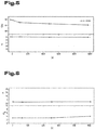
- Fig. 6 the corresponding values for the backside film material 5 are shown.
- a glass fabric / aluminum / PET hybrid film was used as the back film material 5.
- the Yellowness Index (YI) was measured according to ASTM D1925-70 and the elongation at break according to ISO 527.
- YI Yellowness Index
- the time in hours during which the backside film material was exposed to UV radiation is again plotted.
- the ordinate shows the elongation at break ⁇ in percent in the lower part of the picture and the yellowness index in the upper part of the picture.
- FIG. 7 The stress-strain behavior of the ionomer (top line) compared to ICOSOLAR® 2442 (middle line) and ICOSOLAR® AAA 3554 (bottom line). It can be clearly seen that the rear film material 5 according to the invention can absorb higher voltages than conventional materials used for this purpose in photovoltaic elements 1.
- the backing sheet material 5 according to the invention in comparison to conventionally used materials (hatched area) has no (substantial) shrinkage in the transverse or longitudinal direction.
- the negligible shrinkage in comparison to the plastic backing films usually used characterizes the backing film material 5 according to the invention. This results in clear advantages in the handling and lamination of the PV modules.
- the exemplary embodiments show or describe possible design variants of the photovoltaic element 1, it being noted at this point that various combinations of the individual design variants with one another are also possible.
Landscapes
- Photovoltaic Devices (AREA)
- Laminated Bodies (AREA)
Claims (12)
- Élément photovoltaïque (1) comprenant un film d'insertion supérieur (7) un film d'insertion inférieur (8), moyennant quoi, entre les films d'insertion supérieur et inférieur (7, 8), sont intégrées des cellules photovoltaïques (4), ainsi qu'un film arrière (5) qui, lorsque l'élément photovoltaïque (1) est monté, est disposé en dessous du film d'insertion inférieur (8), le film arrière (5) étant constitué d'un film composite qui comprend au moins une couche de matière plastique (9) et au moins un renforcement par des fibres (10), caractérisé en ce que e film composite du film arrière (5) contient au moins une couche de barrière (12) qui est constituée d'au moins un film métallique.
- Élément photovoltaïque (1) selon la revendication 1, caractérisé en ce que le film composite du film arrière (5) comprend au moins une première couche de matière plastique externe (9) et au moins une deuxième couche de matière plastique interne (11), la deuxième couche de matière plastique interne (11) étant moins stabilisée que la première couche de matière plastique externe (9).
- Élément photovoltaïque (1) selon la revendication 1 ou 2, caractérisé en ce que la couche de barrière (12) est constituée d'un film d'aluminium.
- Élément photovoltaïque (1) selon l'une des revendications 1 à 3, caractérisé en ce que le film composite du film arrière (5) comprend une couche constituée d'une matière plastique physiquement réticulée.
- Élément photovoltaïque (1) selon l'une des revendications 1 à 4, caractérisé en ce que la matière plastique physiquement réticulée du film d'insertion (7, 8) est un ionomère.
- Élément photovoltaïque (1) selon la revendication 4 ou 5, caractérisé en ce que la matière plastique physiquement réticulée du film arrière (5) est un ionomère.
- Élément photovoltaïque (1) selon la revendication 6 ou 7, caractérisé en ce que l'ionomère est un ionomère de type zinc à base d'un copolymère éthylène/acide métacrylique.
- Élément photovoltaïque (1) selon l'une des revendications 1 à 7, caractérisé en ce que les différentes couches du film d'insertion (7, 8) et/ou du film arrière (5) sont reliées entre elles par une colle.
- Élément photovoltaïque (1) selon l'une des revendications 1 à 8, caractérisé en ce que le renforcement de fibres (10) est constitué d'au 80 % en poids de verre.
- Élément photovoltaïque (1) selon l'une des revendications 1 à 9, caractérisé en ce que le renforcement de fibres (10) est constitué d'un tissu.
- Élément photovoltaïque (1) selon l'une des revendications 1 à 10, caractérisé en ce qu'une couche constituée du renforcement de fibres (10) présente un poids surfacique entre 100 g/m2 et 250 g/m2.
- Élément photovoltaïque (1) selon l'une des revendications 1 à 11, caractérisé en ce qu'au moins un des deux films d'insertion (7, 8) contient une matière plastique physiquement réticulée.
Applications Claiming Priority (2)
| Application Number | Priority Date | Filing Date | Title |
|---|---|---|---|
| ATA320/2015A AT517402B1 (de) | 2015-05-20 | 2015-05-20 | Photovoltaikelement |
| PCT/AT2016/050146 WO2016183604A1 (fr) | 2015-05-20 | 2016-05-18 | Élément photovoltaïque |
Publications (2)
| Publication Number | Publication Date |
|---|---|
| EP3298631A1 EP3298631A1 (fr) | 2018-03-28 |
| EP3298631B1 true EP3298631B1 (fr) | 2020-03-04 |
Family
ID=56134033
Family Applications (1)
| Application Number | Title | Priority Date | Filing Date |
|---|---|---|---|
| EP16729749.8A Active EP3298631B1 (fr) | 2015-05-20 | 2016-05-18 | Élément photovoltaïque |
Country Status (4)
| Country | Link |
|---|---|
| EP (1) | EP3298631B1 (fr) |
| AT (1) | AT517402B1 (fr) |
| ES (1) | ES2796499T3 (fr) |
| WO (1) | WO2016183604A1 (fr) |
Families Citing this family (2)
| Publication number | Priority date | Publication date | Assignee | Title |
|---|---|---|---|---|
| AT522993B1 (de) * | 2019-09-18 | 2023-05-15 | Lenzing Plastics Gmbh & Co Kg | Photovoltaikelement |
| AT522994B1 (de) * | 2019-09-18 | 2024-11-15 | Lenzing Plastics Gmbh & Co Kg | Photovoltaikelement mit Fasern enthaltendem Einbettfolienmaterial |
Family Cites Families (16)
| Publication number | Priority date | Publication date | Assignee | Title |
|---|---|---|---|---|
| US4636578A (en) * | 1985-04-11 | 1987-01-13 | Atlantic Richfield Company | Photocell assembly |
| US6114046A (en) * | 1997-07-24 | 2000-09-05 | Evergreen Solar, Inc. | Encapsulant material for solar cell module and laminated glass applications |
| WO2007149969A2 (fr) * | 2006-06-21 | 2007-12-27 | Evergreen Solar, Inc. | module photovoltaïque sans cadre |
| DE102009014348A1 (de) * | 2008-06-12 | 2009-12-17 | Bayer Materialscience Ag | Leichtes, biegesteifes und selbsttragendes Solarmodul sowie ein Verfahren zu dessen Herstellung |
| DE102008062286A1 (de) * | 2008-12-03 | 2010-06-10 | P-D Industriegesellschaft mbH Betriebsstätte: Werk Bitterfeld-Laminate | Solarmodul |
| US8609980B2 (en) * | 2010-07-30 | 2013-12-17 | E I Du Pont De Nemours And Company | Cross-linkable ionomeric encapsulants for photovoltaic cells |
| EP2680317A4 (fr) * | 2011-02-23 | 2015-10-07 | Mitsubishi Rayon Co | Module de cellule solaire |
| KR20120132980A (ko) * | 2011-05-30 | 2012-12-10 | 엘지전자 주식회사 | 태양 전지 모듈 |
| KR20130062539A (ko) * | 2011-12-05 | 2013-06-13 | 도레이첨단소재 주식회사 | 방열특성이 우수한 태양전지 백시트 및 그 제조방법 |
| KR101307425B1 (ko) * | 2012-01-13 | 2013-09-11 | 도레이첨단소재 주식회사 | 태양광 모듈용 저수축 봉지재 시트 및 이를 이용한 태양광 모듈 |
| EP2623314A1 (fr) * | 2012-02-06 | 2013-08-07 | Universiteit Twente | Module photovoltaïque encapsulé |
| SG11201405269UA (en) * | 2012-02-29 | 2014-11-27 | Mitsui Chemicals Tohcello Inc | Sheet set for encapsulating solar battery |
| JP6216505B2 (ja) * | 2012-12-07 | 2017-10-18 | 富士電機株式会社 | 太陽電池一体型膜材 |
| AT514090B1 (de) * | 2013-03-26 | 2015-02-15 | Jiangsu Solarflex Technical Composites Ltd | Mehrschichtige Folie für die Rückseite eines Solarmoduls |
| DK2863443T3 (en) * | 2013-10-17 | 2016-08-15 | Das Energy Gmbh | Photovoltaic panel and method for making it |
| CN104393082B (zh) * | 2014-11-14 | 2016-08-24 | 无锡中洁能源技术有限公司 | 一种绝缘型太阳能电池板背膜及其制备方法 |
-
2015
- 2015-05-20 AT ATA320/2015A patent/AT517402B1/de active
-
2016
- 2016-05-18 EP EP16729749.8A patent/EP3298631B1/fr active Active
- 2016-05-18 ES ES16729749T patent/ES2796499T3/es active Active
- 2016-05-18 WO PCT/AT2016/050146 patent/WO2016183604A1/fr not_active Ceased
Non-Patent Citations (1)
| Title |
|---|
| None * |
Also Published As
| Publication number | Publication date |
|---|---|
| ES2796499T3 (es) | 2020-11-27 |
| WO2016183604A1 (fr) | 2016-11-24 |
| AT517402A1 (de) | 2017-01-15 |
| AT517402B1 (de) | 2020-04-15 |
| EP3298631A1 (fr) | 2018-03-28 |
Similar Documents
| Publication | Publication Date | Title |
|---|---|---|
| EP2442977B1 (fr) | Vitrage feuilleté et son utilisation | |
| EP3058597B1 (fr) | Panneau photovoltaïque et son procédé de fabrication | |
| WO2013182399A1 (fr) | Panneau de toit pourvu d'un module photovoltaïque intégré | |
| EP2507057B1 (fr) | Module photovoltaïque et corps coextrudé | |
| DE102007055733A1 (de) | Photovoltaikmodule mit reflektierenden Klebefolien | |
| DE19809883A1 (de) | Solarer Hybridkollektor zur kombinierbaren Strom- und Wärmeerzeugung und ein Verfahren zu seiner Herstellung | |
| DE212012000175U1 (de) | Flexible Photovoltaik-Paneele | |
| EP2530742B1 (fr) | Module de cellules solaires | |
| AT517402B1 (de) | Photovoltaikelement | |
| DE102015002083B4 (de) | Wasserdicht integrierte Leiter in Sandwichbauteilenund Verfahren zur Herstellung der Sandwichbauteile | |
| DE202009017110U1 (de) | Membranbaukomponente | |
| AT522994B1 (de) | Photovoltaikelement mit Fasern enthaltendem Einbettfolienmaterial | |
| AT522993B1 (de) | Photovoltaikelement | |
| EP3856575A1 (fr) | Composant comprenant des éléments fonctionnels électriques pour la production d'une vitre composite | |
| WO2019068929A1 (fr) | Procédé de protection de face arrière de modules photovoltaïques | |
| DE202016008420U1 (de) | Verbundscheibe | |
| EP2462628B1 (fr) | Méthode pour la fabrication de modules photovoltaïques | |
| EP3265509B1 (fr) | Feuille de fond pour cellules solaires | |
| DE102008027265B4 (de) | Solarzellenmodul umfassend eine vorderseitige Glasscheibe sowie rückseitig über eine Klebeverbindung fixierte Profilelemente | |
| DE10158405A1 (de) | Fotovolataikmodul in Form eines Laminats | |
| DE202006014595U1 (de) | Photovoltaikmodul | |
| WO2017108984A1 (fr) | Module photovoltaïque, vitrage isolant et son utilisation | |
| WO1999019914A1 (fr) | Module solaire a fonctions integrees sur la face envers | |
| WO2024251445A1 (fr) | Vitre de véhicule photovoltaïque avec isolation sous vide | |
| WO2025073501A1 (fr) | Vitre feuilletée comprenant un module photovoltaïque |
Legal Events
| Date | Code | Title | Description |
|---|---|---|---|
| STAA | Information on the status of an ep patent application or granted ep patent |
Free format text: STATUS: THE INTERNATIONAL PUBLICATION HAS BEEN MADE |
|
| PUAI | Public reference made under article 153(3) epc to a published international application that has entered the european phase |
Free format text: ORIGINAL CODE: 0009012 |
|
| STAA | Information on the status of an ep patent application or granted ep patent |
Free format text: STATUS: REQUEST FOR EXAMINATION WAS MADE |
|
| 17P | Request for examination filed |
Effective date: 20171005 |
|
| AK | Designated contracting states |
Kind code of ref document: A1 Designated state(s): AL AT BE BG CH CY CZ DE DK EE ES FI FR GB GR HR HU IE IS IT LI LT LU LV MC MK MT NL NO PL PT RO RS SE SI SK SM TR |
|
| AX | Request for extension of the european patent |
Extension state: BA ME |
|
| DAV | Request for validation of the european patent (deleted) | ||
| DAX | Request for extension of the european patent (deleted) | ||
| GRAP | Despatch of communication of intention to grant a patent |
Free format text: ORIGINAL CODE: EPIDOSNIGR1 |
|
| STAA | Information on the status of an ep patent application or granted ep patent |
Free format text: STATUS: GRANT OF PATENT IS INTENDED |
|
| INTG | Intention to grant announced |
Effective date: 20191205 |
|
| GRAS | Grant fee paid |
Free format text: ORIGINAL CODE: EPIDOSNIGR3 |
|
| GRAA | (expected) grant |
Free format text: ORIGINAL CODE: 0009210 |
|
| STAA | Information on the status of an ep patent application or granted ep patent |
Free format text: STATUS: THE PATENT HAS BEEN GRANTED |
|
| AK | Designated contracting states |
Kind code of ref document: B1 Designated state(s): AL AT BE BG CH CY CZ DE DK EE ES FI FR GB GR HR HU IE IS IT LI LT LU LV MC MK MT NL NO PL PT RO RS SE SI SK SM TR |
|
| REG | Reference to a national code |
Ref country code: GB Ref legal event code: FG4D Free format text: NOT ENGLISH |
|
| REG | Reference to a national code |
Ref country code: CH Ref legal event code: EP |
|
| REG | Reference to a national code |
Ref country code: AT Ref legal event code: REF Ref document number: 1241364 Country of ref document: AT Kind code of ref document: T Effective date: 20200315 |
|
| REG | Reference to a national code |
Ref country code: DE Ref legal event code: R096 Ref document number: 502016009032 Country of ref document: DE |
|
| REG | Reference to a national code |
Ref country code: IE Ref legal event code: FG4D Free format text: LANGUAGE OF EP DOCUMENT: GERMAN |
|
| REG | Reference to a national code |
Ref country code: CH Ref legal event code: NV Representative=s name: ABP PATENT NETWORK AG, CH |
|
| PG25 | Lapsed in a contracting state [announced via postgrant information from national office to epo] |
Ref country code: RS Free format text: LAPSE BECAUSE OF FAILURE TO SUBMIT A TRANSLATION OF THE DESCRIPTION OR TO PAY THE FEE WITHIN THE PRESCRIBED TIME-LIMIT Effective date: 20200304 Ref country code: FI Free format text: LAPSE BECAUSE OF FAILURE TO SUBMIT A TRANSLATION OF THE DESCRIPTION OR TO PAY THE FEE WITHIN THE PRESCRIBED TIME-LIMIT Effective date: 20200304 Ref country code: NO Free format text: LAPSE BECAUSE OF FAILURE TO SUBMIT A TRANSLATION OF THE DESCRIPTION OR TO PAY THE FEE WITHIN THE PRESCRIBED TIME-LIMIT Effective date: 20200604 |
|
| REG | Reference to a national code |
Ref country code: NL Ref legal event code: MP Effective date: 20200304 |
|
| PG25 | Lapsed in a contracting state [announced via postgrant information from national office to epo] |
Ref country code: LV Free format text: LAPSE BECAUSE OF FAILURE TO SUBMIT A TRANSLATION OF THE DESCRIPTION OR TO PAY THE FEE WITHIN THE PRESCRIBED TIME-LIMIT Effective date: 20200304 Ref country code: SE Free format text: LAPSE BECAUSE OF FAILURE TO SUBMIT A TRANSLATION OF THE DESCRIPTION OR TO PAY THE FEE WITHIN THE PRESCRIBED TIME-LIMIT Effective date: 20200304 Ref country code: BG Free format text: LAPSE BECAUSE OF FAILURE TO SUBMIT A TRANSLATION OF THE DESCRIPTION OR TO PAY THE FEE WITHIN THE PRESCRIBED TIME-LIMIT Effective date: 20200604 Ref country code: HR Free format text: LAPSE BECAUSE OF FAILURE TO SUBMIT A TRANSLATION OF THE DESCRIPTION OR TO PAY THE FEE WITHIN THE PRESCRIBED TIME-LIMIT Effective date: 20200304 Ref country code: GR Free format text: LAPSE BECAUSE OF FAILURE TO SUBMIT A TRANSLATION OF THE DESCRIPTION OR TO PAY THE FEE WITHIN THE PRESCRIBED TIME-LIMIT Effective date: 20200605 |
|
| REG | Reference to a national code |
Ref country code: LT Ref legal event code: MG4D |
|
| PG25 | Lapsed in a contracting state [announced via postgrant information from national office to epo] |
Ref country code: NL Free format text: LAPSE BECAUSE OF FAILURE TO SUBMIT A TRANSLATION OF THE DESCRIPTION OR TO PAY THE FEE WITHIN THE PRESCRIBED TIME-LIMIT Effective date: 20200304 |
|
| PG25 | Lapsed in a contracting state [announced via postgrant information from national office to epo] |
Ref country code: RO Free format text: LAPSE BECAUSE OF FAILURE TO SUBMIT A TRANSLATION OF THE DESCRIPTION OR TO PAY THE FEE WITHIN THE PRESCRIBED TIME-LIMIT Effective date: 20200304 Ref country code: SK Free format text: LAPSE BECAUSE OF FAILURE TO SUBMIT A TRANSLATION OF THE DESCRIPTION OR TO PAY THE FEE WITHIN THE PRESCRIBED TIME-LIMIT Effective date: 20200304 Ref country code: IS Free format text: LAPSE BECAUSE OF FAILURE TO SUBMIT A TRANSLATION OF THE DESCRIPTION OR TO PAY THE FEE WITHIN THE PRESCRIBED TIME-LIMIT Effective date: 20200704 Ref country code: EE Free format text: LAPSE BECAUSE OF FAILURE TO SUBMIT A TRANSLATION OF THE DESCRIPTION OR TO PAY THE FEE WITHIN THE PRESCRIBED TIME-LIMIT Effective date: 20200304 Ref country code: SM Free format text: LAPSE BECAUSE OF FAILURE TO SUBMIT A TRANSLATION OF THE DESCRIPTION OR TO PAY THE FEE WITHIN THE PRESCRIBED TIME-LIMIT Effective date: 20200304 Ref country code: PT Free format text: LAPSE BECAUSE OF FAILURE TO SUBMIT A TRANSLATION OF THE DESCRIPTION OR TO PAY THE FEE WITHIN THE PRESCRIBED TIME-LIMIT Effective date: 20200729 Ref country code: LT Free format text: LAPSE BECAUSE OF FAILURE TO SUBMIT A TRANSLATION OF THE DESCRIPTION OR TO PAY THE FEE WITHIN THE PRESCRIBED TIME-LIMIT Effective date: 20200304 Ref country code: CZ Free format text: LAPSE BECAUSE OF FAILURE TO SUBMIT A TRANSLATION OF THE DESCRIPTION OR TO PAY THE FEE WITHIN THE PRESCRIBED TIME-LIMIT Effective date: 20200304 |
|
| REG | Reference to a national code |
Ref country code: ES Ref legal event code: FG2A Ref document number: 2796499 Country of ref document: ES Kind code of ref document: T3 Effective date: 20201127 |
|
| REG | Reference to a national code |
Ref country code: DE Ref legal event code: R097 Ref document number: 502016009032 Country of ref document: DE |
|
| PLBE | No opposition filed within time limit |
Free format text: ORIGINAL CODE: 0009261 |
|
| STAA | Information on the status of an ep patent application or granted ep patent |
Free format text: STATUS: NO OPPOSITION FILED WITHIN TIME LIMIT |
|
| PG25 | Lapsed in a contracting state [announced via postgrant information from national office to epo] |
Ref country code: MC Free format text: LAPSE BECAUSE OF FAILURE TO SUBMIT A TRANSLATION OF THE DESCRIPTION OR TO PAY THE FEE WITHIN THE PRESCRIBED TIME-LIMIT Effective date: 20200304 Ref country code: DK Free format text: LAPSE BECAUSE OF FAILURE TO SUBMIT A TRANSLATION OF THE DESCRIPTION OR TO PAY THE FEE WITHIN THE PRESCRIBED TIME-LIMIT Effective date: 20200304 Ref country code: IT Free format text: LAPSE BECAUSE OF FAILURE TO SUBMIT A TRANSLATION OF THE DESCRIPTION OR TO PAY THE FEE WITHIN THE PRESCRIBED TIME-LIMIT Effective date: 20200304 |
|
| 26N | No opposition filed |
Effective date: 20201207 |
|
| PG25 | Lapsed in a contracting state [announced via postgrant information from national office to epo] |
Ref country code: SI Free format text: LAPSE BECAUSE OF FAILURE TO SUBMIT A TRANSLATION OF THE DESCRIPTION OR TO PAY THE FEE WITHIN THE PRESCRIBED TIME-LIMIT Effective date: 20200304 Ref country code: PL Free format text: LAPSE BECAUSE OF FAILURE TO SUBMIT A TRANSLATION OF THE DESCRIPTION OR TO PAY THE FEE WITHIN THE PRESCRIBED TIME-LIMIT Effective date: 20200304 |
|
| REG | Reference to a national code |
Ref country code: BE Ref legal event code: MM Effective date: 20200531 |
|
| PG25 | Lapsed in a contracting state [announced via postgrant information from national office to epo] |
Ref country code: LU Free format text: LAPSE BECAUSE OF NON-PAYMENT OF DUE FEES Effective date: 20200518 |
|
| PG25 | Lapsed in a contracting state [announced via postgrant information from national office to epo] |
Ref country code: IE Free format text: LAPSE BECAUSE OF NON-PAYMENT OF DUE FEES Effective date: 20200518 |
|
| PG25 | Lapsed in a contracting state [announced via postgrant information from national office to epo] |
Ref country code: BE Free format text: LAPSE BECAUSE OF NON-PAYMENT OF DUE FEES Effective date: 20200531 |
|
| PG25 | Lapsed in a contracting state [announced via postgrant information from national office to epo] |
Ref country code: TR Free format text: LAPSE BECAUSE OF FAILURE TO SUBMIT A TRANSLATION OF THE DESCRIPTION OR TO PAY THE FEE WITHIN THE PRESCRIBED TIME-LIMIT Effective date: 20200304 Ref country code: MT Free format text: LAPSE BECAUSE OF FAILURE TO SUBMIT A TRANSLATION OF THE DESCRIPTION OR TO PAY THE FEE WITHIN THE PRESCRIBED TIME-LIMIT Effective date: 20200304 Ref country code: CY Free format text: LAPSE BECAUSE OF FAILURE TO SUBMIT A TRANSLATION OF THE DESCRIPTION OR TO PAY THE FEE WITHIN THE PRESCRIBED TIME-LIMIT Effective date: 20200304 |
|
| PG25 | Lapsed in a contracting state [announced via postgrant information from national office to epo] |
Ref country code: MK Free format text: LAPSE BECAUSE OF FAILURE TO SUBMIT A TRANSLATION OF THE DESCRIPTION OR TO PAY THE FEE WITHIN THE PRESCRIBED TIME-LIMIT Effective date: 20200304 Ref country code: AL Free format text: LAPSE BECAUSE OF FAILURE TO SUBMIT A TRANSLATION OF THE DESCRIPTION OR TO PAY THE FEE WITHIN THE PRESCRIBED TIME-LIMIT Effective date: 20200304 |
|
| REG | Reference to a national code |
Ref country code: AT Ref legal event code: MM01 Ref document number: 1241364 Country of ref document: AT Kind code of ref document: T Effective date: 20210518 |
|
| PG25 | Lapsed in a contracting state [announced via postgrant information from national office to epo] |
Ref country code: AT Free format text: LAPSE BECAUSE OF NON-PAYMENT OF DUE FEES Effective date: 20210518 |
|
| P01 | Opt-out of the competence of the unified patent court (upc) registered |
Effective date: 20230601 |
|
| REG | Reference to a national code |
Ref country code: DE Ref legal event code: R079 Ref document number: 502016009032 Country of ref document: DE Free format text: PREVIOUS MAIN CLASS: H01L0031048000 Ipc: H10F0019800000 |
|
| PGFP | Annual fee paid to national office [announced via postgrant information from national office to epo] |
Ref country code: DE Payment date: 20250523 Year of fee payment: 10 |
|
| PGFP | Annual fee paid to national office [announced via postgrant information from national office to epo] |
Ref country code: ES Payment date: 20250606 Year of fee payment: 10 |
|
| PGFP | Annual fee paid to national office [announced via postgrant information from national office to epo] |
Ref country code: FR Payment date: 20250526 Year of fee payment: 10 |
|
| PGFP | Annual fee paid to national office [announced via postgrant information from national office to epo] |
Ref country code: CH Payment date: 20250612 Year of fee payment: 10 |
|
| PGFP | Annual fee paid to national office [announced via postgrant information from national office to epo] |
Ref country code: GB Payment date: 20260330 Year of fee payment: 11 |