EP3298634B1 - Verbundfadenstruktur - Google Patents
Verbundfadenstruktur Download PDFInfo
- Publication number
- EP3298634B1 EP3298634B1 EP16725460.6A EP16725460A EP3298634B1 EP 3298634 B1 EP3298634 B1 EP 3298634B1 EP 16725460 A EP16725460 A EP 16725460A EP 3298634 B1 EP3298634 B1 EP 3298634B1
- Authority
- EP
- European Patent Office
- Prior art keywords
- yarn structure
- conductive
- piezoelectric
- composite yarn
- component
- Prior art date
- Legal status (The legal status is an assumption and is not a legal conclusion. Google has not performed a legal analysis and makes no representation as to the accuracy of the status listed.)
- Active
Links
Images

Classifications
-
- H—ELECTRICITY
- H10—SEMICONDUCTOR DEVICES; ELECTRIC SOLID-STATE DEVICES NOT OTHERWISE PROVIDED FOR
- H10N—ELECTRIC SOLID-STATE DEVICES NOT OTHERWISE PROVIDED FOR
- H10N30/00—Piezoelectric or electrostrictive devices
- H10N30/60—Piezoelectric or electrostrictive devices having a coaxial cable structure
-
- D—TEXTILES; PAPER
- D02—YARNS; MECHANICAL FINISHING OF YARNS OR ROPES; WARPING OR BEAMING
- D02G—CRIMPING OR CURLING FIBRES, FILAMENTS, THREADS, OR YARNS; YARNS OR THREADS
- D02G3/00—Yarns or threads, e.g. fancy yarns; Processes or apparatus for the production thereof, not otherwise provided for
- D02G3/22—Yarns or threads characterised by constructional features, e.g. blending, filament/fibre
- D02G3/32—Elastic yarns or threads ; Production of plied or cored yarns, one of which is elastic
-
- D—TEXTILES; PAPER
- D02—YARNS; MECHANICAL FINISHING OF YARNS OR ROPES; WARPING OR BEAMING
- D02G—CRIMPING OR CURLING FIBRES, FILAMENTS, THREADS, OR YARNS; YARNS OR THREADS
- D02G3/00—Yarns or threads, e.g. fancy yarns; Processes or apparatus for the production thereof, not otherwise provided for
- D02G3/22—Yarns or threads characterised by constructional features, e.g. blending, filament/fibre
- D02G3/38—Threads in which fibres, filaments, or yarns are wound with other yarns or filaments, e.g. wrap yarns, i.e. strands of filaments or staple fibres are wrapped by a helically wound binder yarn
-
- D—TEXTILES; PAPER
- D02—YARNS; MECHANICAL FINISHING OF YARNS OR ROPES; WARPING OR BEAMING
- D02G—CRIMPING OR CURLING FIBRES, FILAMENTS, THREADS, OR YARNS; YARNS OR THREADS
- D02G3/00—Yarns or threads, e.g. fancy yarns; Processes or apparatus for the production thereof, not otherwise provided for
- D02G3/44—Yarns or threads characterised by the purpose for which they are designed
- D02G3/441—Yarns or threads with antistatic, conductive or radiation-shielding properties
-
- H—ELECTRICITY
- H10—SEMICONDUCTOR DEVICES; ELECTRIC SOLID-STATE DEVICES NOT OTHERWISE PROVIDED FOR
- H10N—ELECTRIC SOLID-STATE DEVICES NOT OTHERWISE PROVIDED FOR
- H10N30/00—Piezoelectric or electrostrictive devices
- H10N30/702—Piezoelectric or electrostrictive devices based on piezoelectric or electrostrictive fibres
-
- H—ELECTRICITY
- H10—SEMICONDUCTOR DEVICES; ELECTRIC SOLID-STATE DEVICES NOT OTHERWISE PROVIDED FOR
- H10N—ELECTRIC SOLID-STATE DEVICES NOT OTHERWISE PROVIDED FOR
- H10N30/00—Piezoelectric or electrostrictive devices
- H10N30/80—Constructional details
- H10N30/85—Piezoelectric or electrostrictive active materials
- H10N30/857—Macromolecular compositions
-
- H—ELECTRICITY
- H10—SEMICONDUCTOR DEVICES; ELECTRIC SOLID-STATE DEVICES NOT OTHERWISE PROVIDED FOR
- H10N—ELECTRIC SOLID-STATE DEVICES NOT OTHERWISE PROVIDED FOR
- H10N30/00—Piezoelectric or electrostrictive devices
- H10N30/80—Constructional details
- H10N30/87—Electrodes or interconnections, e.g. leads or terminals
- H10N30/877—Conductive materials
- H10N30/878—Conductive materials the principal material being non-metallic, e.g. oxide or carbon based
-
- D—TEXTILES; PAPER
- D10—INDEXING SCHEME ASSOCIATED WITH SUBLASSES OF SECTION D, RELATING TO TEXTILES
- D10B—INDEXING SCHEME ASSOCIATED WITH SUBLASSES OF SECTION D, RELATING TO TEXTILES
- D10B2401/00—Physical properties
- D10B2401/16—Physical properties antistatic; conductive
Definitions
- the present invention relates to a composite yarn structure, in particular to a piezoelectric yarn structure in the fields of textile construction engineering and of flexible devices physics.
- Piezoelectricity is the electric charge that is generated in certain materials in response to an applied mechanical stress.
- piezoelectric materials develop electrical potential across defined layers of the material upon pressure, strain or pulses or a combination thereof.
- the piezoelectric effect is reversible, i.e. the materials in which an electrical charge is generated from an applied mechanical stress also exhibit the internal generation of a mechanical strain resulting from an applied electrical field. Piezoelectric phenomena are known and have been studied for more than a century.
- Piezoelectric devices are used in many technical fields, for example in valves and for energy harvesting and for sensing applications.
- energy harvesting in textiles has been actively investigated; to this purpose piezoelectric yarns have been provided.
- WO 2014/161920 discloses a method for producing a piezoelectric and pyroelectric fiber, wherein the fiber has a core material comprising an electrically conductive flexible thermoplastic composite comprising at least one polymer and at least one conductive filler.
- the fiber further comprises a surrounding material made of a permanently polarizable polymer.
- the piezoelectric yarn may be further twisted together with a conductive yarn.
- Document EP 0187829 B1 discloses a cable structure which allows a sensible piezoelectric response in a piezoelectric coaxial cable.
- the coaxial cable has a conductive polymer core comprising a polymeric material in which conductive particles are provided, a piezoelectric polymer layer surrounding the conductive polymer core, and an outer conductor surrounding the piezoelectric polymer layer.
- the cable is also provided with an outer protective jacket.
- GB 2516987 discloses a fabric having a three-dimensional spacer structure, comprising a piezoelectric material acting as a spacer between knitted or woven fabric layers, for harvesting energy via the conversion of mechanical energy into electrical energy.
- the fabric layers comprise conductive fibres, while the interconnecting piezoelectric spacer yarns comprise piezoelectric fibres, which can be monofilaments and/or multifilaments.
- the first and second layers may comprise film-like or solid fabric materials.
- a further aim of the invention is to provide a piezoelectric yarn with increased piezoelectric effect.
- the invention relates to a composite yarn structure having a first element comprising a coaxial flexible bi-component monofilament including a conductive component and a thermoplastic component exhibiting piezoelectric properties; at least a second conductive element arranged around at least part of the first element to provide a piezoelectric yarn, characterized in that said piezoelectric yarn has auxetic properties.
- the invention relates to a composite yarn structure having:
- the second element is a conductive element or comprises a conductive element to provide the required piezoelectric effect.
- the second element may be inelastic, i.e. it may have a limited stretch (elongation) capability, lower than the stretch (elongation) properties of the first element; in other words, the second element does not elongate or elongates very little.
- the behavior of the yarn is comparable to or is the same as the behavior of an auxetic yarn; the constraint against elongation provided by the second element having a low elasticity, or in other words, high rigidity obliges the first filament element to expand transversally to the direction of the elongation, bending and twisting around the stretched second element.
- the first element shape has a substantially rectilinear shape; the second element is twisted around the first rectilinear element in a helix.
- the second element Upon stretching, the second element is brought into a substantially or almost rectilinear shape, along the direction of stretching - elongation; once the second element has been pulled into a substantially rectilinear condition, it cannot be further stretched because of his inelastic properties, i.e. because the second element cannot be elongated in the same way as the first element.
- This change of status of the second, non-elastic element of the yarn of the present invention obliges the elastic first element to change from its initial rectilinear shape into a helix/sinusoidal condition in which the first element is twisted around the second element.
- the result is an increase in the overall dimensions of the yarn, namely of the width of the overall yarn; the composite yarn can thus be said to have auxetic properties.
- the invention provides a new class of yarn structures which can create, by means of a combination of an auxetic and a piezoelectric effect, an enhanced electric potential difference between two conductors.
- Another object of the invention is an article that exploits such combination of auxetic and a piezoelectric effects to increase electric potential difference created in the article.
- Exemplary articles are fabrics, garments, clothes and ropes.
- Another object of the invention is to provide a textile yarn and a fabric including such textile yarns that may be employed in application such as textile sensors.
- Auxetic materials are known since the late 1980's. Auxetic materials are materials that get thicker and/or wider along a first direction, upon stretching along a second direction perpendicular to the first direction, contrariwise to many ordinary materials. The opposite behavior is also known, namely narrowing upon pressure, instead of getting wider as expected from ordinary materials.
- an effect of the invention is that when the yarn structure is subjected to a force acting in an axial direction, the whole structure also expands in a transversal direction, giving rise to an auxetic effect.
- the yarn structure is piezoelectric
- the combination of the properties of auxeticity and of piezoelectricity in a single yarn increase the produced pressure onto the piezoelectric material by effect of the expansion of the yarn, hence the generated electric potential difference is increased.
- the second element upon elongation of the yarn structure in a first direction, the second element is stretched to an almost rectilinear position and deforms the first element in such a way as to shape the first element in a helix fashion in the second direction, around the first element.
- An effect of this embodiment is that when the yarn structure is used in a fabric, the auxetic effect increases the width of all the piezoelectric yarns present in the fabric, a phenomenon which produces additional pressure through all of the piezoelectric components, leading to an additional potential development between respective conductors.
- Another aspect of the invention provides a textile fabric comprising a plurality of composite yarn structures, wherein said composite yarn structures comprise:
- the direction in which the first element expands is angled to and may be substantially perpendicular to the first direction, according to an exemplary embodiment.
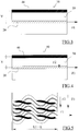
- Figure 1A shows an embodiment of the composite yarn structure 10, according to the invention, in two different configurations.
- the composite yarn structure 10 comprises a first element 15 comprising a coaxial flexible bi-component monofilament including a conductive component 20 and a thermoplastic component 30 exhibiting piezoelectric properties. As visible in Figures 1-2 , in an embodiment of the invention, the thermoplastic component 30 surrounds the conductive component 10.
- Suitable materials for the conductive component 20 are blends of low-density polyethylene (LDPE) or High-density polyethylene (HDPE) with carbon nanotubes (CNTs), graphite, graphene nano-sheets, carbon black (amorphous carbon), polyaniline (doped), polypyrrole (doped).
- LDPE low-density polyethylene
- HDPE High-density polyethylene
- CNTs carbon nanotubes
- graphite graphite
- graphene nano-sheets carbon black (amorphous carbon
- polyaniline doped
- polypyrrole doped
- thermoplastic component 30 Suitable materials for the thermoplastic component 30 are polyvinylidene fluoride (PVDF) homopolymer and its copolymers with trifluoroethylene P(VDF-co-TrFE) or tetrafluoroethylene P(VDF-co-TFE), odd numbered polyamides (PA) such as PA5, PA7, PA11 and so on.
- PVDF polyvinylidene fluoride
- PA odd numbered polyamides
- components 20 and 30, forming the first element 15, have elastic properties and can be elongated.
- the composite yarn structure 10 further comprises a second element 40 twisted around the first element 15.
- the second element 40 has a tensile strength greater than a tensile strength of the first element 15.
- the second element 40 has a lower elasticity with respect to the elasticity of the first element 15 or, in other words, a higher rigidity with respect to the rigidity of the first element 15.
- Figure 1A shows the disposition of the composite yarn of the invention in an unstretched condition; in this condition, first element 15 extends in a substantially rectilinear direction and second element 40 is twisted around first element 30 to provide a plurality of turns.
- the difference in elasticity between first and second elements is such that, upon stretching and elongation of the yarn's structure 10 in a first direction (see fig. 1B ), i.e. in the direction of the axis of first element, the initial shape of structure 10 is deformed by the movement of second element 40; namely the yarn's structure expands in a second direction that is angled or substantially perpendicular to the first direction, i.e. to direction of elongation of the yarn, that is corresponding to the direction of arrow F in figures 1 and 2 .
- the second element 40 Upon elongation of the yarn structure 10, the second element 40 is substantially aligned with the elongation direction and the first element 15 expands by forming a series of curves around the second element 40. Such curves are angled with respect to the elongation direction by an angle ⁇ comprised between 30° and 90°, preferably 30° to 80°, as shown in Figure 1B .
- a possible way to measure elasticity is to use the Young's modulus, also known as the tensile modulus or elastic modulus, namely a measure of the stiffness of an elastic material defined as the ratio of the stress (force per unit area) along an axis to the strain (ratio of deformation over initial length) along that axis in the range of stress in which Hooke's law holds.
- Hooke's law states that the force needed to extend or compress a material by some distance is proportional to that distance.
- the tensile strength of the first element is in the range of 15 - 78 MPa.
- the tensile strength of the second element is preferably in the range of 0.5 - 2.0 GPa.
- the difference in tensile strength of second to first element is of at least 422 MPa.
- Tensile strength is measured according to ASTM D638. Other methods of measuring tensile strength may be used.
- Suitable materials for the second element are silver/copper coated polyester/polyamide yarns or fully metal filament yarns e.g. made of steel.
- the second element 40 may be made of at least one metallic filament.
- the composite yarn structure 10 disclosed can be used as a flexible piezoelectric yarn sensor which also exhibit auxetic features, in order to maximize its performance when used within a fabric construction or in another article made of yarns.
- the composite yarn structure 10 when the composite yarn structure 10 is subjected to a force F greater than zero in a longitudinal direction, e.g. along the axis, of the composite yarn, a shape transformation of the composite yarn structure 10 occurs. Namely the structure 10 is elongated by a length L but, at the same time, the structure 10 expands transversally in a perpendicular or angled direction with respect to the direction of the force F. As visible in the figures, the yarn increases its overall width after being stretched by force F, starting from an initial width of X and reaching a larger width of X + Y.
- the second element 40 elongates and, at the same time, stretches the first element 15 in such a way as to shape the first element 15 in an almost sinusoidal fashion in the second direction.
- the yarn expands transversally.
- a piezo-auxetic synergistic effect in the whole fabric may also be realized if at least two composite yarns of the invention are adjacent to each other, i.e. they are close enough to be mutually biased by the expansion step.
- the first effect is the fact that the yarn structure 10 exhibits piezoelectric features thanks to the transverse pressure through the piezoelectric material created upon stretching, for example by applying the force F.
- the second effect is that this pressure is exponentially higher within a fabric compared to a single yarn of the same structure, thanks to the fact that all the piezoelectric yarns forming the fabric gets wider, a phenomenon that produces additional pressure through all of the piezoelectric components, leading to an additional potential development between respective conductors.
- the composite yarn structure 10 can create an enhanced potential difference between two conductors by piezoelectricity and exhibits a negative Poisson's ratio, upon stretching, whereby the Poisson ratio is defined as the percentage of expansion divided by the percentage of compression in transversal direction of a material.
- the composite yarn of the invention, 10 by using its auxetic features, produces an enhanced electric potential difference due to additional forces that originate from the fact that individual fibers experience an increased transverse pressure compared to yarns that are piezoelectric but not auxetic within the same woven structure.
- piezoelectric constants are in use, such as d33, namely the volume change when a piezoelectric material is subject to an electric field, rather than d31.
- piezoelectric constants also known as piezoelectricity coefficients, quantifies the volume change when a piezoelectric material is subject to an electric field, or its polarization on application of a stress.
- a portion of tensile stimuli are translated to transverse stimuli within a fabric construction due to auxeticity.
- first element 15 i.e. the bicomponent element
- an additional force F3 may be defined.
- Force F3 defines, in addition to forces F1 and F2, another additional gain factor when the yarn is embodied within a fabric or in a rope.
- the total force acting upon the piezoelectric component 30 increases to a value of F2+F3.
- the value F3 represents the value of the force originating from the fact that neighboring yarns in the fabric or rope structure, which might also be auxetic, exert additional forces against each other resisting their widening due to the auxetic effect.
- This phenomenon may increase the overall pressure on the piezoelectric material of component 30. Within a certain range, this phenomenon helps to obtain more overall efficiency of the final yarn as a strain sensor.
- a further parameter to take into consideration may be the twisting angle of second element 40, which defines the number of turns per unit length of the whole yarn.
- the twisting angle is defined e.g. by the softness of the central bicomponent and may be calibrated accordingly: if the number of turns is more than necessary, then the auxetic behavior will not be present as the central bicomponent will have enough mechanic resistance against being bent.
- the number of turns must be sufficient to cover the length L1 of the yarn structure 10 in a non-elongated configuration and to allow to reach the length L1 + L when the yarn structure is in an elongated configuration. If the number of turns is less than necessary, then the d2 coefficient will not have a significant additional term, therefore, the additional gain will not be as high as it otherwise could.
- the thickness of the piezoelectric layer its thickness is usually within the range from a few hundreds of nano-meters to a few hundreds of micro-meters radially, namely 100 nm to 800 ⁇ m as measured radially having as centre the center of bicomponent first element.
- additional second elements may be used, provided that the additional second elements strictly follow the path of conductive second element 40 in order not to destroy the yarn geometry required to create the auxeticity phenomenon.
- all the optional twisting second elements should be in-phase or synchronized with one another.
- conductive second element 40 and all the possible additional second elements should be twisted first to create a twisting filament bundle; the twisting filament bundle is then twisted around the central bicomponent element 15.
- the optional additional second elements may be conductive or isolating.
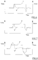
- Figure 6 shows a curve V representing electric potential as a function of a force F applied to the yarn structure in the configuration of Figure 1A ; in the case of Figure 6 , a relatively small force F is applied to the yarn structure 10, leaving it substantially in the configuration represented on Figure 1A . No significant auxetic deformation is therefore present.
- curve F represents (not in scale) the force applied to the yarn structure 10 and curve V the electric potential due to the piezoelectric effect which follows a smooth Landau kind of potential distribution over time. It is noted also that the shape of the potential curve is not distorted.
- Figure 7 shows a curve V' representing electric potential as a function of a stronger force (curve F') applied to the yarn structure in the configuration of Figure 1B .
- curve V' representing electric potential as a function of a stronger force applied to the yarn structure in the configuration of Figure 1B .
- an additional electric potential development (curve V') is generated and is added to the one represented in Figure 6 .
- Figure 8 shows a curve V" representing an electric potential as a function of forces (curve F") applied when the yarn structure is embedded into the fabric of Figure 5 .
- a plurality of yarn structures are incorporated within a fabric construction or a rope or similar textile structure where each yarn structure experiences the effect of neighboring auxetic yarns and the pressure created by such neighboring yarns. This phenomenon further distorts the electric potential shape (curve V") because a third component of the force, namely F3, is experienced by the yarn structures.
- a weighted combination of the piezoelectric coefficients are in use.
- the conductive component 20 of the first element 15 may be made of an elastic conductive material.
- the elastic conductive material of the conductive component 20 of the first element 15 may be a polymer including conductive metallic impurities.
- conductive metallic impurities may be made of silver or copper.
- the elastic conductive material of the conductive component 20 of the first element 15 may be an intrinsically conductive polymer.
- such intrinsically conductive polymers may be polyaniline (PANI) or polypyrrole (PPy).
- the thermoplastic component of the composite yarn structure 10 may be made of polyvinylidene fluoride (PVDF) or of any other suitable thermoplastic polymer.
- the drawn coaxial components are polarized under a strong electric field after heating to align the thermoplastic polymer chain.
- An optimum drawing ratio can be chosen to perform the drawing, in the absence of an electric field, of the coaxial components in order to impose the piezoelectric phase in the thermoplastic polymer.
- yarn structure of the invention Possible applications of the yarn structure of the invention are, among others, i) wearable sensor technology for body position monitoring in fabric form and ii) tensile monitoring of ropes used in a variety of areas from mountain climbing to heavy marine applications.
- thermoplastic component 30 may have auxetic properties per se, in addition to the auxetic effect given to the whole yarn structure 10 by the second element 40.
Landscapes
- Engineering & Computer Science (AREA)
- Mechanical Engineering (AREA)
- Textile Engineering (AREA)
- Physics & Mathematics (AREA)
- Spectroscopy & Molecular Physics (AREA)
- Woven Fabrics (AREA)
- Yarns And Mechanical Finishing Of Yarns Or Ropes (AREA)
- Multicomponent Fibers (AREA)
Claims (13)
- Verbundgarnstruktur (10) mit einem ersten Element (15), umfassend ein koaxiales, flexibles Zweikomponenten-Monofilament einschließend eine leitfähige Komponente (20) und eine piezoelektrische Eigenschaften aufweisende, thermoplastische Komponente (30); mindestens ein zweites, leitfähiges Element (40), das um mindestens einen Teil des ersten Elements (15) angeordnet ist, um ein piezoelektrisches Garn (10) bereitzustellen, dadurch gekennzeichnet, dass das piezoelektrische Garn (10) auxetische Eigenschaften aufweist, und dass die leitfähige Komponente (20) des ersten Elements (15) aus einem elastischen leitfähigen Polymer besteht, welches leitfähige metallische Verunreinigungen enthält, oder aus einem Material, das aus Gemischen von Polyethylen niedriger Dichte (LDPE) oder Polyethylen hoher Dichte (HDPE) ausgewählt ist mit mindestens einem Teil Kohlenstoffnanoröhren (CNTs), Graphit, Graphen-Nanoblättern, amorphem Kohlenstoff, dotiertem Polyanilin oder dotiertem Polypyrrol oder Mischungen davon.
- Verbundgarnstruktur (10) gemäß Anspruch 1, umfassend:- ein erstes Element (15) umfassend ein koaxiales, flexibles Zweikomponenten-Monofilament umfasst, einschließend eine leitfähige Komponente (20) und eine piezoelektrische Eigenschaften aufweisende, thermoplastische Komponente (30),- mindestens ein um das erste Element (15) gewickeltes, zweites Element (40), wobei das zweite Element (40) in Bezug auf die Elastizität des ersten Elements (15) eine geringere Elastizität aufweist, so dass sich bei einer Dehnung der Garnstruktur (10) in einer ersten Richtung die Garnstruktur (10) in eine zweite Richtung ausdehnt, wodurch die Abmessungen des Garns sowohl in der ersten als auch in der zweiten Richtung vergrößert werden, um eine zusätzliche Kraft auf die piezoelektrische Komponente des ersten Elements zu erzeugen.
- Verbundgarnstruktur (10) gemäß Anspruch 2, wobei das zweite Element (40) ein leitfähiges Element ist oder ein leitfähiges Element umfasst.
- Verbundgarnstruktur gemäß Anspruch 3, wobei das zweite Element (40) bei Verlängerung der Garnstruktur (10) in der ersten Richtung das erste Element (15) derart formt, dass es einen auxetischen Effekt bereitstellt.
- Verbundgarnstruktur gemäß Anspruch 4, wobei das zweite Element das erste Element (15) zu einer Helix um das zweite Element umformt.
- Verbundgarnstruktur (10) gemäß Anspruch 1, wobei das elastische leitfähige Material der leitfähigen Komponente des ersten Elements (15) ein intrinsisch leitendes Polymer ist.
- Verbundgarnstruktur (10) nach einem der vorhergehenden Ansprüche, wobei die thermoplastische Komponente (30) ein Material umfasst, das aus Polyvinylidenfluorid (PVDF) -Homopolymer und dessen Copolymeren zusammen mit Trifluorethylen P (VDF-co-TrFE) oder Tetrafluorethylen P (VDF-co-TFE) oder ungeradzahlig nummerierten Polyamide (PA).
- Verbundgarnstruktur (10) gemäß einem der vorhergehenden Ansprüche, wobei die thermoplastische Komponente (30) auxetische Eigenschaften aufweist.
- Verbundgarnstruktur (10) gemäß einem der vorhergehenden Ansprüche, wobei das zweite Element (40) eine Vielzahl von Filamenten umfasst, wobei mindestens ein Filament ein leitfähiges Filament ist, vorzugsweise ein Metallfilament.
- Verbundgarnstruktur (10) gemäß einem der vorhergehenden Ansprüche, wobei die Komponenten des ersten Elements (15) co-extrudiert sind.
- Gegenstand, der mindestens eine Verbundgarnstruktur (10) gemäß einem der vorhergehenden Ansprüche umfasst.
- Artikel gemäß Anspruch 11, wobei mindestens zwei Garne gemäß einem der Ansprüche 1 bis 10 nebeneinander angeordnet sind, um sich nach dem Dehnen gegenseitig vorzuspannen.
- Gegenstand gemäß Anspruch 11 oder 12, wobei der Gegenstand ausgewählt ist aus einem Stoff, einem Kleidungsstück, Kleidungsstücken und einem Seil.
Priority Applications (1)
| Application Number | Priority Date | Filing Date | Title |
|---|---|---|---|
| PL16725460T PL3298634T3 (pl) | 2015-05-22 | 2016-05-19 | Struktura przędzy kompozytowej |
Applications Claiming Priority (2)
| Application Number | Priority Date | Filing Date | Title |
|---|---|---|---|
| EP15169045.0A EP3096368B1 (de) | 2015-05-22 | 2015-05-22 | Verbundfadenstruktur |
| PCT/EP2016/061264 WO2016188853A1 (en) | 2015-05-22 | 2016-05-19 | A composite yarn structure |
Publications (2)
| Publication Number | Publication Date |
|---|---|
| EP3298634A1 EP3298634A1 (de) | 2018-03-28 |
| EP3298634B1 true EP3298634B1 (de) | 2019-06-26 |
Family
ID=53191588
Family Applications (2)
| Application Number | Title | Priority Date | Filing Date |
|---|---|---|---|
| EP15169045.0A Active EP3096368B1 (de) | 2015-05-22 | 2015-05-22 | Verbundfadenstruktur |
| EP16725460.6A Active EP3298634B1 (de) | 2015-05-22 | 2016-05-19 | Verbundfadenstruktur |
Family Applications Before (1)
| Application Number | Title | Priority Date | Filing Date |
|---|---|---|---|
| EP15169045.0A Active EP3096368B1 (de) | 2015-05-22 | 2015-05-22 | Verbundfadenstruktur |
Country Status (11)
| Country | Link |
|---|---|
| US (1) | US11437562B2 (de) |
| EP (2) | EP3096368B1 (de) |
| JP (1) | JP6952607B2 (de) |
| CN (1) | CN107896497B (de) |
| BR (1) | BR112017024870B1 (de) |
| DK (2) | DK3096368T3 (de) |
| ES (2) | ES2642098T3 (de) |
| HK (1) | HK1250839B (de) |
| PL (2) | PL3096368T3 (de) |
| PT (2) | PT3096368T (de) |
| WO (1) | WO2016188853A1 (de) |
Families Citing this family (36)
| Publication number | Priority date | Publication date | Assignee | Title |
|---|---|---|---|---|
| US10982381B2 (en) | 2014-10-06 | 2021-04-20 | Natural Fiber Welding, Inc. | Methods, processes, and apparatuses for producing welded substrates |
| US10011931B2 (en) | 2014-10-06 | 2018-07-03 | Natural Fiber Welding, Inc. | Methods, processes, and apparatuses for producing dyed and welded substrates |
| US10447178B1 (en) * | 2016-02-02 | 2019-10-15 | Brrr! Inc. | Systems, articles of manufacture, apparatus and methods employing piezoelectrics for energy harvesting |
| EP3433416B1 (de) | 2016-03-25 | 2023-12-06 | Natural Fiber Welding, Inc. | Verfahren zur herstellung von einem geschweissten substrat |
| DE102016106071A1 (de) * | 2016-04-04 | 2017-10-05 | Pilz Gmbh & Co. Kg | Gewebe mit mehreren Gewebelagen und Verfahren zu dessen Herstellung |
| DE102016106074A1 (de) * | 2016-04-04 | 2017-10-05 | Pilz Gmbh & Co. Kg | Gewebe mit mehreren Gewebelagen |
| AU2017259983B2 (en) | 2016-05-03 | 2021-08-19 | Natural Fiber Welding, Inc. | Methods, processes, and apparatuses for producing dyed and welded substrates |
| WO2017212523A1 (ja) * | 2016-06-06 | 2017-12-14 | 株式会社村田製作所 | 菌対策用圧電糸、菌対策用布、布、衣料、医療部材、生体作用圧電糸、および物質吸着用圧電糸 |
| WO2018084055A1 (ja) | 2016-11-01 | 2018-05-11 | 株式会社村田製作所 | 抗菌性不織部材、抗菌性不織布、および抗菌性緩衝材 |
| JP6842059B2 (ja) * | 2017-01-11 | 2021-03-17 | 帝人フロンティア株式会社 | 圧電構造体及びそれを用いたデバイス |
| CN106971865B (zh) * | 2017-04-28 | 2019-01-15 | 东华大学 | 一种具有高比电容的聚苯胺/碳纳米管/棉织物复合柔性电极及其制备和应用 |
| CN109287121B (zh) * | 2017-05-19 | 2022-02-11 | 株式会社村田制作所 | 抗菌纱、座椅和座套 |
| WO2018216253A1 (ja) * | 2017-05-26 | 2018-11-29 | 株式会社村田製作所 | 繊維製品およびその製造方法 |
| CN107254724B (zh) * | 2017-07-04 | 2019-04-09 | 东华大学 | 一种负泊松比纱的三轴系锥筒式复合纺纱装置与方法 |
| CN107400947B (zh) * | 2017-07-04 | 2020-07-31 | 东华大学 | 一种环锭纺的负泊松比纱及其复合纺纱装置、方法与用途 |
| KR102312154B1 (ko) * | 2017-08-09 | 2021-10-12 | 미쯔이가가꾸가부시끼가이샤 | 센서 모듈 및 이것을 구비한 압력 분포 센서 |
| TWI829660B (zh) | 2017-11-11 | 2024-01-21 | 美商天然纖維焊接股份有限公司 | 紗與熔接紗 |
| CN108166122A (zh) * | 2018-02-08 | 2018-06-15 | 湖北枫树线业有限公司 | 具有拉伸膨胀性能的单复丝双股缝纫线及其制造方法 |
| CN109267199A (zh) * | 2018-08-16 | 2019-01-25 | 吉祥三宝高科纺织有限公司 | 一种导电聚苯胺/碳纳米管纤维复合材料及其制备方法和用途 |
| US10597798B1 (en) * | 2018-12-28 | 2020-03-24 | Brrr! Inc. | Methods and compositions for cooling yarns and fabrics, and articles comprising same |
| JP7475002B2 (ja) * | 2019-03-29 | 2024-04-26 | ユニチカ株式会社 | 圧電センサを用いた繊維構造体 |
| WO2020210646A1 (en) | 2019-04-10 | 2020-10-15 | Propel, LLC | Systems for maintaining moisture in a textile electrode |
| CN109936306B (zh) * | 2019-04-19 | 2022-04-12 | 嘉兴学院 | 一种发电织物结构 |
| CN110055647B (zh) * | 2019-05-06 | 2024-04-16 | 江南大学 | 一种反向双层包缠结构负泊松比复合纱线及其四通道空心锭纺纱装置和控制方法 |
| WO2020241432A1 (ja) * | 2019-05-28 | 2020-12-03 | 帝人フロンティア株式会社 | 糸および布 |
| CN110396743B (zh) * | 2019-07-10 | 2021-03-23 | 上海八达纺织印染服装有限公司 | 一种具有负泊松比效应的纱线及纺纱方法 |
| CN111074417A (zh) * | 2019-11-28 | 2020-04-28 | 江苏品创纺织科技有限公司 | 一种具备电磁屏蔽功能的面料的制备方法 |
| CN111005126A (zh) * | 2019-12-31 | 2020-04-14 | 正凯纺织有限公司 | 环保免染薄型绉格面料及其制备方法 |
| EP4141155A4 (de) * | 2020-04-23 | 2024-04-17 | Seiren Co., Ltd. | Leitfähiges garn und artikel mit aus dem leitfähigen garn geformter verdrahtungsleitung |
| US11905651B2 (en) * | 2020-06-18 | 2024-02-20 | Swift Textile Metalizing LLC | Auxetic fabric reinforced elastomers |
| WO2022260649A1 (en) | 2021-06-08 | 2022-12-15 | Jm Mark Inc. | Medicinal fabric for dermatological use cases |
| KR102694951B1 (ko) * | 2021-11-19 | 2024-08-13 | 부산대학교 산학협력단 | 미세유체 장치를 사용하여 미세섬유를 제조하는 방법 및 상기 미세섬유를 포함하는 스트레인 센서 |
| CN114438657B (zh) * | 2021-12-29 | 2023-08-01 | 东华大学 | 一种低成本摩擦发电针织间隔织物 |
| FR3132915B1 (fr) * | 2022-02-18 | 2024-11-08 | Safran | Toron destiné à la formation d’une préforme fibreuse d’une pièce en matériau composite |
| CN116145300B (zh) * | 2023-03-08 | 2024-04-30 | 苏州红旭新材料科技有限公司 | 一种具有负泊松比效应的电磁屏蔽功能弹性纱线 |
| CN116905147B (zh) * | 2023-04-25 | 2026-02-27 | 东华大学 | 一种复合管状结构拉胀纱线的加工装置、方法及用途 |
Family Cites Families (15)
| Publication number | Priority date | Publication date | Assignee | Title |
|---|---|---|---|---|
| ATE70666T1 (de) | 1984-07-06 | 1992-01-15 | Focas Ltd | Piezoelektrisches koaxialkabel. |
| US4568851A (en) * | 1984-09-11 | 1986-02-04 | Raychem Corporation | Piezoelectric coaxial cable having a helical inner conductor |
| US5334903A (en) | 1992-12-04 | 1994-08-02 | The United States Of America As Represented By The Secretary Of The Navy | Composite piezoelectrics utilizing a negative Poisson ratio polymer |
| US6271621B1 (en) * | 1998-08-05 | 2001-08-07 | Matsushita Electric Industrial Co., Ltd. | Piezoelectric pressure sensor |
| US7348285B2 (en) * | 2002-06-28 | 2008-03-25 | North Carolina State University | Fabric and yarn structures for improving signal integrity in fabric-based electrical circuits |
| GB0307330D0 (en) * | 2003-03-29 | 2003-05-07 | Dow Corning Ltd | Improvements in and relating to composite materials and structures |
| US20080099960A1 (en) * | 2004-08-31 | 2008-05-01 | Hidenori Okuzaki | Deformation Method of Polymer Film or Fiber, and Polymer Actuator |
| CN105696138B (zh) * | 2004-11-09 | 2019-02-01 | 得克萨斯大学体系董事会 | 纳米纤维纱线、带和板的制造和应用 |
| GB2426255B (en) * | 2005-05-16 | 2009-09-23 | Univ Manchester | Operative devices |
| CN103361811B (zh) * | 2012-06-26 | 2016-03-30 | 香港理工大学 | 一种负泊松比纱线结构及其制造方法 |
| WO2014058077A1 (ja) * | 2012-10-12 | 2014-04-17 | 帝人株式会社 | 圧電素子 |
| WO2014161920A1 (en) | 2013-04-03 | 2014-10-09 | Swerea Ivf Ab | Method of producing a piezoelectric and pyroelectric fiber |
| CN104233579A (zh) * | 2013-06-20 | 2014-12-24 | 扬州思必得仪器设备有限公司 | 一种含芯压电纤维织物 |
| GB201313911D0 (en) | 2013-08-02 | 2013-09-18 | Univ Bolton | Energy harvesting piezoelectric three-dimensional spacer structures |
| KR101781680B1 (ko) * | 2014-12-02 | 2017-09-25 | 한양대학교 산학협력단 | 유연성 및 신축성이 우수한 압전 섬유 및 이의 제조방법 |
-
2015
- 2015-05-22 DK DK15169045.0T patent/DK3096368T3/en active
- 2015-05-22 ES ES15169045.0T patent/ES2642098T3/es active Active
- 2015-05-22 PT PT151690450T patent/PT3096368T/pt unknown
- 2015-05-22 EP EP15169045.0A patent/EP3096368B1/de active Active
- 2015-05-22 PL PL15169045T patent/PL3096368T3/pl unknown
-
2016
- 2016-05-19 JP JP2017560661A patent/JP6952607B2/ja not_active Expired - Fee Related
- 2016-05-19 ES ES16725460T patent/ES2746298T3/es active Active
- 2016-05-19 EP EP16725460.6A patent/EP3298634B1/de active Active
- 2016-05-19 PL PL16725460T patent/PL3298634T3/pl unknown
- 2016-05-19 CN CN201680029503.9A patent/CN107896497B/zh active Active
- 2016-05-19 PT PT167254606T patent/PT3298634T/pt unknown
- 2016-05-19 US US15/575,017 patent/US11437562B2/en active Active
- 2016-05-19 WO PCT/EP2016/061264 patent/WO2016188853A1/en not_active Ceased
- 2016-05-19 HK HK18109970.5A patent/HK1250839B/en unknown
- 2016-05-19 BR BR112017024870-0A patent/BR112017024870B1/pt active IP Right Grant
- 2016-05-19 DK DK16725460.6T patent/DK3298634T3/da active
Non-Patent Citations (1)
| Title |
|---|
| None * |
Also Published As
| Publication number | Publication date |
|---|---|
| PT3298634T (pt) | 2019-10-14 |
| PL3096368T3 (pl) | 2017-12-29 |
| PL3298634T3 (pl) | 2020-01-31 |
| WO2016188853A1 (en) | 2016-12-01 |
| BR112017024870B1 (pt) | 2022-07-05 |
| CN107896497B (zh) | 2021-11-02 |
| US11437562B2 (en) | 2022-09-06 |
| DK3298634T3 (da) | 2019-10-07 |
| JP2018521501A (ja) | 2018-08-02 |
| HK1250839B (en) | 2020-03-20 |
| EP3096368B1 (de) | 2017-08-30 |
| DK3096368T3 (en) | 2017-12-04 |
| ES2642098T3 (es) | 2017-11-15 |
| ES2746298T3 (es) | 2020-03-05 |
| US20180151795A1 (en) | 2018-05-31 |
| PT3096368T (pt) | 2017-10-04 |
| BR112017024870A2 (pt) | 2018-08-07 |
| EP3096368A1 (de) | 2016-11-23 |
| JP6952607B2 (ja) | 2021-10-20 |
| EP3298634A1 (de) | 2018-03-28 |
| CN107896497A (zh) | 2018-04-10 |
Similar Documents
| Publication | Publication Date | Title |
|---|---|---|
| EP3096368B1 (de) | Verbundfadenstruktur | |
| HK1250839A1 (en) | A composite yarn structure | |
| Liu et al. | Functionalized fiber-based strain sensors: pathway to next-generation wearable electronics | |
| CN107923083B (zh) | 纺织织物 | |
| Ma et al. | Piezoelectric and optoelectronic properties of electrospinning hybrid PVDF and ZnO nanofibers | |
| US10756251B2 (en) | Piezoelectric fiber having excellent flexibility and elasticity, and method for manufacturing the same | |
| CN1768176B (zh) | 具有负值或实际负值泊松比的复合元件及其制造方法 | |
| KR101730396B1 (ko) | 전기방사하여 얻은 나노섬유 웹 형태의 pla 압전소재를 이용한 압력측정 센서 | |
| WO2014161920A1 (en) | Method of producing a piezoelectric and pyroelectric fiber | |
| Hong et al. | Smart fabric strain sensor comprising reduced graphene oxide with structure-based negative piezoresistivity | |
| Zhong et al. | Continuous fabrication of core-sheath fiber for strain sensing and self-powered application | |
| CN102564290A (zh) | 一种基于碳纳米管三维编织复合材料的健康监测方法 | |
| HK1230346B (en) | A composite yarn structure | |
| HK1230346A1 (en) | A composite yarn structure | |
| HK1230346A (en) | A composite yarn structure | |
| Roy et al. | Use of piezoelectric polymers for smart textiles | |
| KR102798010B1 (ko) | 계층적 코일-플라이 구조를 갖는 섬유 구조체 및 그 제조 방법 | |
| Temesgen et al. | Conductive fabrics and their application in technical textiles via Arduino uno microcontroller | |
| Roy et al. | Department of Textile and Fibre Engineering, Indian Institute of Technology Delhi, New Delhi, India | |
| HK1255552B (en) | A woven textile fabric | |
| YUKSELOGLU et al. | PIEZOELECTRIC POLYMERS IN TEXTILE INDUSTRY. | |
| Temesgenº et al. | Conductive Fabrics and their Application in Technical Textiles via |
Legal Events
| Date | Code | Title | Description |
|---|---|---|---|
| STAA | Information on the status of an ep patent application or granted ep patent |
Free format text: STATUS: THE INTERNATIONAL PUBLICATION HAS BEEN MADE |
|
| PUAI | Public reference made under article 153(3) epc to a published international application that has entered the european phase |
Free format text: ORIGINAL CODE: 0009012 |
|
| STAA | Information on the status of an ep patent application or granted ep patent |
Free format text: STATUS: REQUEST FOR EXAMINATION WAS MADE |
|
| 17P | Request for examination filed |
Effective date: 20171201 |
|
| AK | Designated contracting states |
Kind code of ref document: A1 Designated state(s): AL AT BE BG CH CY CZ DE DK EE ES FI FR GB GR HR HU IE IS IT LI LT LU LV MC MK MT NL NO PL PT RO RS SE SI SK SM TR |
|
| AX | Request for extension of the european patent |
Extension state: BA ME |
|
| DAV | Request for validation of the european patent (deleted) | ||
| DAX | Request for extension of the european patent (deleted) | ||
| GRAP | Despatch of communication of intention to grant a patent |
Free format text: ORIGINAL CODE: EPIDOSNIGR1 |
|
| STAA | Information on the status of an ep patent application or granted ep patent |
Free format text: STATUS: GRANT OF PATENT IS INTENDED |
|
| INTG | Intention to grant announced |
Effective date: 20181205 |
|
| REG | Reference to a national code |
Ref country code: HK Ref legal event code: DE Ref document number: 1250839 Country of ref document: HK |
|
| GRAJ | Information related to disapproval of communication of intention to grant by the applicant or resumption of examination proceedings by the epo deleted |
Free format text: ORIGINAL CODE: EPIDOSDIGR1 |
|
| STAA | Information on the status of an ep patent application or granted ep patent |
Free format text: STATUS: REQUEST FOR EXAMINATION WAS MADE |
|
| GRAR | Information related to intention to grant a patent recorded |
Free format text: ORIGINAL CODE: EPIDOSNIGR71 |
|
| GRAS | Grant fee paid |
Free format text: ORIGINAL CODE: EPIDOSNIGR3 |
|
| STAA | Information on the status of an ep patent application or granted ep patent |
Free format text: STATUS: GRANT OF PATENT IS INTENDED |
|
| INTC | Intention to grant announced (deleted) | ||
| GRAA | (expected) grant |
Free format text: ORIGINAL CODE: 0009210 |
|
| STAA | Information on the status of an ep patent application or granted ep patent |
Free format text: STATUS: THE PATENT HAS BEEN GRANTED |
|
| INTG | Intention to grant announced |
Effective date: 20190507 |
|
| AK | Designated contracting states |
Kind code of ref document: B1 Designated state(s): AL AT BE BG CH CY CZ DE DK EE ES FI FR GB GR HR HU IE IS IT LI LT LU LV MC MK MT NL NO PL PT RO RS SE SI SK SM TR |
|
| REG | Reference to a national code |
Ref country code: GB Ref legal event code: FG4D |
|
| REG | Reference to a national code |
Ref country code: CH Ref legal event code: EP |
|
| REG | Reference to a national code |
Ref country code: AT Ref legal event code: REF Ref document number: 1149323 Country of ref document: AT Kind code of ref document: T Effective date: 20190715 |
|
| REG | Reference to a national code |
Ref country code: DE Ref legal event code: R096 Ref document number: 602016015934 Country of ref document: DE |
|
| REG | Reference to a national code |
Ref country code: IE Ref legal event code: FG4D |
|
| REG | Reference to a national code |
Ref country code: NL Ref legal event code: FP |
|
| REG | Reference to a national code |
Ref country code: DK Ref legal event code: T3 Effective date: 20191003 |
|
| REG | Reference to a national code |
Ref country code: NO Ref legal event code: T2 Effective date: 20190626 Ref country code: PT Ref legal event code: SC4A Ref document number: 3298634 Country of ref document: PT Date of ref document: 20191014 Kind code of ref document: T Free format text: AVAILABILITY OF NATIONAL TRANSLATION Effective date: 20190925 |
|
| REG | Reference to a national code |
Ref country code: SE Ref legal event code: TRGR |
|
| PG25 | Lapsed in a contracting state [announced via postgrant information from national office to epo] |
Ref country code: HR Free format text: LAPSE BECAUSE OF FAILURE TO SUBMIT A TRANSLATION OF THE DESCRIPTION OR TO PAY THE FEE WITHIN THE PRESCRIBED TIME-LIMIT Effective date: 20190626 Ref country code: LT Free format text: LAPSE BECAUSE OF FAILURE TO SUBMIT A TRANSLATION OF THE DESCRIPTION OR TO PAY THE FEE WITHIN THE PRESCRIBED TIME-LIMIT Effective date: 20190626 Ref country code: AL Free format text: LAPSE BECAUSE OF FAILURE TO SUBMIT A TRANSLATION OF THE DESCRIPTION OR TO PAY THE FEE WITHIN THE PRESCRIBED TIME-LIMIT Effective date: 20190626 Ref country code: FI Free format text: LAPSE BECAUSE OF FAILURE TO SUBMIT A TRANSLATION OF THE DESCRIPTION OR TO PAY THE FEE WITHIN THE PRESCRIBED TIME-LIMIT Effective date: 20190626 |
|
| REG | Reference to a national code |
Ref country code: LT Ref legal event code: MG4D |
|
| PG25 | Lapsed in a contracting state [announced via postgrant information from national office to epo] |
Ref country code: RS Free format text: LAPSE BECAUSE OF FAILURE TO SUBMIT A TRANSLATION OF THE DESCRIPTION OR TO PAY THE FEE WITHIN THE PRESCRIBED TIME-LIMIT Effective date: 20190626 Ref country code: LV Free format text: LAPSE BECAUSE OF FAILURE TO SUBMIT A TRANSLATION OF THE DESCRIPTION OR TO PAY THE FEE WITHIN THE PRESCRIBED TIME-LIMIT Effective date: 20190626 Ref country code: GR Free format text: LAPSE BECAUSE OF FAILURE TO SUBMIT A TRANSLATION OF THE DESCRIPTION OR TO PAY THE FEE WITHIN THE PRESCRIBED TIME-LIMIT Effective date: 20190927 Ref country code: BG Free format text: LAPSE BECAUSE OF FAILURE TO SUBMIT A TRANSLATION OF THE DESCRIPTION OR TO PAY THE FEE WITHIN THE PRESCRIBED TIME-LIMIT Effective date: 20190926 |
|
| REG | Reference to a national code |
Ref country code: AT Ref legal event code: MK05 Ref document number: 1149323 Country of ref document: AT Kind code of ref document: T Effective date: 20190626 |
|
| PG25 | Lapsed in a contracting state [announced via postgrant information from national office to epo] |
Ref country code: CZ Free format text: LAPSE BECAUSE OF FAILURE TO SUBMIT A TRANSLATION OF THE DESCRIPTION OR TO PAY THE FEE WITHIN THE PRESCRIBED TIME-LIMIT Effective date: 20190626 Ref country code: RO Free format text: LAPSE BECAUSE OF FAILURE TO SUBMIT A TRANSLATION OF THE DESCRIPTION OR TO PAY THE FEE WITHIN THE PRESCRIBED TIME-LIMIT Effective date: 20190626 Ref country code: SK Free format text: LAPSE BECAUSE OF FAILURE TO SUBMIT A TRANSLATION OF THE DESCRIPTION OR TO PAY THE FEE WITHIN THE PRESCRIBED TIME-LIMIT Effective date: 20190626 Ref country code: AT Free format text: LAPSE BECAUSE OF FAILURE TO SUBMIT A TRANSLATION OF THE DESCRIPTION OR TO PAY THE FEE WITHIN THE PRESCRIBED TIME-LIMIT Effective date: 20190626 Ref country code: EE Free format text: LAPSE BECAUSE OF FAILURE TO SUBMIT A TRANSLATION OF THE DESCRIPTION OR TO PAY THE FEE WITHIN THE PRESCRIBED TIME-LIMIT Effective date: 20190626 |
|
| PG25 | Lapsed in a contracting state [announced via postgrant information from national office to epo] |
Ref country code: IS Free format text: LAPSE BECAUSE OF FAILURE TO SUBMIT A TRANSLATION OF THE DESCRIPTION OR TO PAY THE FEE WITHIN THE PRESCRIBED TIME-LIMIT Effective date: 20191026 Ref country code: SM Free format text: LAPSE BECAUSE OF FAILURE TO SUBMIT A TRANSLATION OF THE DESCRIPTION OR TO PAY THE FEE WITHIN THE PRESCRIBED TIME-LIMIT Effective date: 20190626 |
|
| REG | Reference to a national code |
Ref country code: ES Ref legal event code: FG2A Ref document number: 2746298 Country of ref document: ES Kind code of ref document: T3 Effective date: 20200305 |
|
| PG25 | Lapsed in a contracting state [announced via postgrant information from national office to epo] |
Ref country code: IS Free format text: LAPSE BECAUSE OF FAILURE TO SUBMIT A TRANSLATION OF THE DESCRIPTION OR TO PAY THE FEE WITHIN THE PRESCRIBED TIME-LIMIT Effective date: 20200224 |
|
| REG | Reference to a national code |
Ref country code: DE Ref legal event code: R097 Ref document number: 602016015934 Country of ref document: DE |
|
| PLBE | No opposition filed within time limit |
Free format text: ORIGINAL CODE: 0009261 |
|
| STAA | Information on the status of an ep patent application or granted ep patent |
Free format text: STATUS: NO OPPOSITION FILED WITHIN TIME LIMIT |
|
| PG2D | Information on lapse in contracting state deleted |
Ref country code: IS |
|
| 26N | No opposition filed |
Effective date: 20200603 |
|
| PG25 | Lapsed in a contracting state [announced via postgrant information from national office to epo] |
Ref country code: SI Free format text: LAPSE BECAUSE OF FAILURE TO SUBMIT A TRANSLATION OF THE DESCRIPTION OR TO PAY THE FEE WITHIN THE PRESCRIBED TIME-LIMIT Effective date: 20190626 |
|
| PG25 | Lapsed in a contracting state [announced via postgrant information from national office to epo] |
Ref country code: MC Free format text: LAPSE BECAUSE OF FAILURE TO SUBMIT A TRANSLATION OF THE DESCRIPTION OR TO PAY THE FEE WITHIN THE PRESCRIBED TIME-LIMIT Effective date: 20190626 Ref country code: CH Free format text: LAPSE BECAUSE OF NON-PAYMENT OF DUE FEES Effective date: 20200531 Ref country code: LI Free format text: LAPSE BECAUSE OF NON-PAYMENT OF DUE FEES Effective date: 20200531 |
|
| REG | Reference to a national code |
Ref country code: BE Ref legal event code: MM Effective date: 20200531 |
|
| PG25 | Lapsed in a contracting state [announced via postgrant information from national office to epo] |
Ref country code: LU Free format text: LAPSE BECAUSE OF NON-PAYMENT OF DUE FEES Effective date: 20200519 |
|
| PG25 | Lapsed in a contracting state [announced via postgrant information from national office to epo] |
Ref country code: IE Free format text: LAPSE BECAUSE OF NON-PAYMENT OF DUE FEES Effective date: 20200519 |
|
| PG25 | Lapsed in a contracting state [announced via postgrant information from national office to epo] |
Ref country code: BE Free format text: LAPSE BECAUSE OF NON-PAYMENT OF DUE FEES Effective date: 20200531 |
|
| PG25 | Lapsed in a contracting state [announced via postgrant information from national office to epo] |
Ref country code: MT Free format text: LAPSE BECAUSE OF FAILURE TO SUBMIT A TRANSLATION OF THE DESCRIPTION OR TO PAY THE FEE WITHIN THE PRESCRIBED TIME-LIMIT Effective date: 20190626 Ref country code: CY Free format text: LAPSE BECAUSE OF FAILURE TO SUBMIT A TRANSLATION OF THE DESCRIPTION OR TO PAY THE FEE WITHIN THE PRESCRIBED TIME-LIMIT Effective date: 20190626 |
|
| PG25 | Lapsed in a contracting state [announced via postgrant information from national office to epo] |
Ref country code: MK Free format text: LAPSE BECAUSE OF FAILURE TO SUBMIT A TRANSLATION OF THE DESCRIPTION OR TO PAY THE FEE WITHIN THE PRESCRIBED TIME-LIMIT Effective date: 20190626 |
|
| REG | Reference to a national code |
Ref country code: DE Ref legal event code: R079 Ref document number: 602016015934 Country of ref document: DE Free format text: PREVIOUS MAIN CLASS: H01L0041087000 Ipc: H10N0030600000 |
|
| P01 | Opt-out of the competence of the unified patent court (upc) registered |
Effective date: 20230419 |
|
| PGFP | Annual fee paid to national office [announced via postgrant information from national office to epo] |
Ref country code: NL Payment date: 20250526 Year of fee payment: 10 |
|
| PGFP | Annual fee paid to national office [announced via postgrant information from national office to epo] |
Ref country code: PL Payment date: 20250507 Year of fee payment: 10 Ref country code: DE Payment date: 20250414 Year of fee payment: 10 |
|
| PGFP | Annual fee paid to national office [announced via postgrant information from national office to epo] |
Ref country code: GB Payment date: 20250512 Year of fee payment: 10 Ref country code: ES Payment date: 20250603 Year of fee payment: 10 Ref country code: DK Payment date: 20250526 Year of fee payment: 10 |
|
| PGFP | Annual fee paid to national office [announced via postgrant information from national office to epo] |
Ref country code: NO Payment date: 20250530 Year of fee payment: 10 |
|
| PGFP | Annual fee paid to national office [announced via postgrant information from national office to epo] |
Ref country code: IT Payment date: 20250509 Year of fee payment: 10 |
|
| PGFP | Annual fee paid to national office [announced via postgrant information from national office to epo] |
Ref country code: PT Payment date: 20250505 Year of fee payment: 10 |
|
| PGFP | Annual fee paid to national office [announced via postgrant information from national office to epo] |
Ref country code: FR Payment date: 20250526 Year of fee payment: 10 |
|
| PGFP | Annual fee paid to national office [announced via postgrant information from national office to epo] |
Ref country code: TR Payment date: 20250515 Year of fee payment: 10 |
|
| PGFP | Annual fee paid to national office [announced via postgrant information from national office to epo] |
Ref country code: SE Payment date: 20250527 Year of fee payment: 10 |