EP3298879A1 - Barre de coupe - Google Patents
Barre de coupe Download PDFInfo
- Publication number
- EP3298879A1 EP3298879A1 EP17168329.5A EP17168329A EP3298879A1 EP 3298879 A1 EP3298879 A1 EP 3298879A1 EP 17168329 A EP17168329 A EP 17168329A EP 3298879 A1 EP3298879 A1 EP 3298879A1
- Authority
- EP
- European Patent Office
- Prior art keywords
- conveyor belt
- cutting unit
- wedge
- component
- center section
- Prior art date
- Legal status (The legal status is an assumption and is not a legal conclusion. Google has not performed a legal analysis and makes no representation as to the accuracy of the status listed.)
- Granted
Links
Images


Classifications
-
- A—HUMAN NECESSITIES
- A01—AGRICULTURE; FORESTRY; ANIMAL HUSBANDRY; HUNTING; TRAPPING; FISHING
- A01D—HARVESTING; MOWING
- A01D41/00—Combines, i.e. harvesters or mowers combined with threshing devices
- A01D41/12—Details of combines
- A01D41/14—Mowing tables
-
- A—HUMAN NECESSITIES
- A01—AGRICULTURE; FORESTRY; ANIMAL HUSBANDRY; HUNTING; TRAPPING; FISHING
- A01D—HARVESTING; MOWING
- A01D61/00—Elevators or conveyors for binders or combines
- A01D61/008—Elevators or conveyors for binders or combines for longitudinal conveying, especially for combines
-
- A—HUMAN NECESSITIES
- A01—AGRICULTURE; FORESTRY; ANIMAL HUSBANDRY; HUNTING; TRAPPING; FISHING
- A01D—HARVESTING; MOWING
- A01D34/00—Mowers; Mowing apparatus of harvesters
- A01D34/01—Mowers; Mowing apparatus of harvesters characterised by features relating to the type of cutting apparatus
- A01D34/02—Mowers; Mowing apparatus of harvesters characterised by features relating to the type of cutting apparatus having reciprocating cutters
- A01D34/03—Mowers; Mowing apparatus of harvesters characterised by features relating to the type of cutting apparatus having reciprocating cutters mounted on a vehicle, e.g. a tractor, or drawn by an animal or a vehicle
- A01D34/04—Mowers; Mowing apparatus of harvesters characterised by features relating to the type of cutting apparatus having reciprocating cutters mounted on a vehicle, e.g. a tractor, or drawn by an animal or a vehicle with cutters at the front
-
- A—HUMAN NECESSITIES
- A01—AGRICULTURE; FORESTRY; ANIMAL HUSBANDRY; HUNTING; TRAPPING; FISHING
- A01D—HARVESTING; MOWING
- A01D57/00—Delivering mechanisms for harvesters or mowers
- A01D57/20—Delivering mechanisms for harvesters or mowers with conveyor belts
-
- A—HUMAN NECESSITIES
- A01—AGRICULTURE; FORESTRY; ANIMAL HUSBANDRY; HUNTING; TRAPPING; FISHING
- A01D—HARVESTING; MOWING
- A01D61/00—Elevators or conveyors for binders or combines
- A01D61/02—Endless belts
-
- A—HUMAN NECESSITIES
- A01—AGRICULTURE; FORESTRY; ANIMAL HUSBANDRY; HUNTING; TRAPPING; FISHING
- A01D—HARVESTING; MOWING
- A01D61/00—Elevators or conveyors for binders or combines
- A01D61/002—Elevators or conveyors for binders or combines transversal conveying devices
Definitions
- the present invention relates to a cutting unit, comprising a center section arranged on a base frame and at least two side sections arranged adjacent to the center section, a cutter bar extending essentially across the width of the cutting mechanism and at least one conveyor device arranged behind the cutter bar, which crop material is cut by the cutter bar transported sideways in the direction of the center section, which has at least one conveying means conveying transversely to the transport direction of the conveying device.
- Cutting units of the type mentioned above are designed as so-called tape cutting units, which are characterized by a high degree of flexibility in adapting to a bottom contour of a surface to be processed. This is achieved by dispensing with an inherently rigid cutting table, as is common in cereal cutting in general.
- the side sections each have at least one endlessly circulating, driven conveyor belt, which is supported by a plurality of support arms of the respective side section which are pivotable about an axis of rotation.
- ribbon cutting plants are known whose side sections and cutter bars are rigid.
- the respective conveyor belts transport by means of the cutter bar harvested crop in the lateral direction, that is transverse to the longitudinal axis of the cutting unit, to the center section.
- the center section has at least one conveying means which conveys transversely to the transport direction of the conveyor belts and which accepts and diverts the laterally supplied crop.
- a generic cutting unit is from the US 6,817,166 B2 known.
- the US 6,817,166 B2 describes a cutting unit with a center section arranged on a base frame and at least two side sections arranged adjacent to the center section.
- a cutter bar extending substantially across the width of the cutting unit serves to harvest crops.
- Behind the cutter bar a conveyor device is arranged on the respective side section, which conveys the crop cut off by the cutter bar sideways in the direction of the center section.
- the middle section comprises a conveying means which conveys transversely to the transport direction of the conveying device and which is designed as an endlessly circulating conveyor belt.
- the surface of the conveyor belt is provided with a plurality of seen in transport or conveying direction in pairs successively arranged strips.
- the juxtaposed strips have seen in the transport direction of the conveyor belt on a slight inclination.
- the arrangement is chosen such that the outer, the outer edges of the conveyor belt facing ends of the strips in front of the ends in the middle of the conveyor belt facing each other in the transport direction. These strips are intended to improve the acceptance of the output of the conveyor belts of the side sections to the lower conveyor belt of the center section crop.
- the conveying means comprises at least two endlessly circulating conveyor belts which are arranged inclined at an angle to the longitudinal axis of the central portion.
- the inclined arrangement of the conveyor belts makes it possible to bring the crop to the center of the middle section, so that less crop accumulates on the sides of the center section.
- the transition areas from the conveyor belts of the side sections to the conveyor belts of the center section are relieved by this arrangement by the entrainment of the crop is reduced by the respective conveyor belt of the adjacent side portion to the bottom of the cutting unit. As a result, less header losses occur.
- the risk of blockages due to accumulating crops in the transition area is also significantly reduced.
- the crop tends to become trapped in the transition region between the sideways conveyor belts and the transversely extending, lower-lying conveyor belt, resulting in blockage of the cutter.
- the arrangement according to the invention of at least two conveyor belts on the center section means that the crop coming from the side sections is not deflected almost at right angles when receiving the goods through the conveyor belts of the center section, as in the cutting device according to FIG US 6,817,166 B2 the case is.
- Another disadvantage of the from the US 6,817,166 B2 known conveyor belt in the middle region results from the inclined direction of the conveying arrangement of the strips on the conveyor belt surface.
- the inclination of the strips with respect to the longitudinal axis of the conveyor can be made only very low, otherwise there will be problems in the field of drive and pulleys, leading to damage to the conveyor belt. Also conceivable is an arrangement of at least one further conveyor belt in the middle region of the cutting mechanism, which is arranged between the conveyor belts arranged inclined.
- the at least two conveyor belts are arranged substantially V-shaped, wherein the conveyor belts converge in the transport direction.
- the two conveyor belts of the middle section in each case enclose the same angle with the longitudinal axis.
- a component which has an essentially wedge-shaped course in its longitudinal extent extends between the conveyor belts.
- the wedge-shaped component at least partially covers the region between the conveyor belts arranged inclined with respect to the longitudinal axis of the center section.
- the surface of the wedge-shaped component may be located at least in sections at a height with the top of the conveyor belts.
- the component may have a tapering in the transport direction of the conveyor belts course.
- the wedge-shaped component should be adapted substantially to the course of the arrangement of the conveyor belts in the center section. As a result, open areas between the conveyor belts in the center section can be avoided. In this way, the passage of crop in particular between the endless circulating conveyor belts can be prevented.
- the wedge-shaped component may have a roof-shaped surface, which is designed to sloping down to the component limiting outer longitudinal edges.
- the wedge-shaped component may have a triangular cross section.
- the wedge-shaped component can preferably have an outwardly extending section at its outer longitudinal edges facing the respective conveyor belt, which section sections the surface of the respective conveyor belt overlaps.
- The, in particular convex, section serves to seal the respectively adjacently arranged conveyor belt, in order to prevent crops from getting between the respective endlessly circulating conveyor belt.
- the respective section may also have a substantially L-shaped profile.
- At least one sealing element made of an elastic material can be arranged on the side of the respective section facing the conveyor belt.
- the sealing element rests on the surface of the conveyor belt.
- the component can be releasably mounted on a frame member of the center section.
- a simple interchangeability of the wedge-shaped component is ensured.
- easy access to the adjacent to the wedge-shaped component arranged conveyor belts in the middle section is given.
- the respective conveyor belt can surround two rollers arranged parallel to one another and a tensioning device arranged between the rollers for adapting the spacing of the rollers in sections.
- the clamping device between the rotating conveyor belt can be a space-saving accommodation achieve.
- the tensioning device may have an actuating lever which projects laterally beyond the outer edge of the conveyor belt on the side facing the wedge-shaped element and extends parallel to the conveyor belt in a closed position.
- a preferred development may be that the conveyor belts of the center section are independently drivable.
- a suitable monitoring of the recorded from the side portions of the cutting unit Erntegutmengen and a control of the respective actuators of the conveyor belts can react to temporary fluctuations in the acceptance of goods by the conveyor belts in the middle section.
- Fig. 1 is a schematic partial view of a cutting unit 1 shown in plan view.
- the cutting unit 1 is designed as a so-called band cutter, which has a high degree of flexibility in adapting to a bottom contour of a surface to be processed or to be harvested.
- the cutting unit 1 has a base frame 2 on which a center section 3 and at least two side sections 4 arranged adjacent to the center section 3 are arranged.
- a knife bar 6 is arranged on the front side opposite the base frame 2 and extends essentially over the entire width of the cutting mechanism 1.
- reels are arranged, extending over the width of a side portion 4 and partially across the width of Center section 3 extend. The reels serve to improve the acceptance of the crop by the cutter bar. 6
- the crop separated from the cutter bar 6 is fed to a conveying device 5 arranged behind the cutter bar 6, which comprises on the respective side sections 4 at least one endlessly circulating side conveyor belt 7.
- the endlessly circulating side conveyor belts 7 are arranged adjacent to the center section 3 in order to transport the crop cut off by the cutter bar 6 parallel to the longitudinal axis of the cutting mechanism 1 in the direction of the center section 3.
- the crop is fed to a collection device 8.
- the intake device 8 is designed as a drivable feed roller 9, which is mounted by frame members on the base frame 2.
- the feed roller 9 has retractable fingers 10.
- the collection device 8 performs the of the endless conveyor belts 7 the middle section 3 laterally supplied crop of a provided in the base frame 2, located behind the feed roller 9, opening, through which the crops cut by a hinted only indentation port 11 of a combine harvester on which the Cutting unit 1 is fastened, the combine harvester for further processing is transferred.
- the middle section 3 has a conveying means 12 which comprises at least two endlessly circulating conveyor belts 13a, 13b.
- Arrows indicated by the reference symbol TR indicate the transport or conveying direction of the conveyor belts 13a, 13b.
- the two conveyor belts 13a, 13b are arranged inclined to a longitudinal axis LA of the center section 3.
- the side conveyor belts 7 arranged adjacent to the side sections 4 overlap the respective conveyor belt 13a, 13b in sections.
- the arrangement of the conveyor belts 13a, 13b is chosen such that it is substantially V-shaped. For this purpose, the two conveyor belts 13a, 13b arranged converging in the transport direction TR.
- the respective conveyor belt 13a, 13b encloses an angle ⁇ with the longitudinal axis of the center section 3 which is greater than or equal to 5 °.
- This arrangement has the advantage that the of the side conveyor belts. 7 coming crops not, as is known in the art, must be redirected at the transition to the center region by an angle of 90 °.
- the V-shaped arrangement of the conveyor belts 13a, 13b leads to a merging of the crop in the central region of the center section 3, so that a backlog of crop on the center section 3 is reduced to the side conveyor belts 7 out.
- a component 14 having a wedge-shaped course in its longitudinal direction is arranged between the conveyor belts 13a, 13b of the middle section 3.
- the component 14 has a tapering in the transport direction TR of the conveyor belts 13a, 13b course.
- the component 14 essentially extends between the two conveyor belts 13a, 13b, so that the area remaining free due to the inclined arrangement of the two conveyor belts 13a, 13b is covered.
- the arrangement of a further conveyor belt between the two V-shaped conveyor belts 13a, 13b is also conceivable.
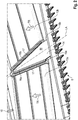
- the representation in Fig. 2 shows a perspective detail V of the cutting unit 1 according to Fig. 1 with the component 14 having a wedge-shaped profile.
- the component 14 is preferably made in one piece.
- An at least two-part embodiment of the component 14 is also conceivable, wherein in a two-part design of the component 14, the two parts with respect to the longitudinal axis LA of the central portion 3 would be constructed in mirror image.
- the component 14 At its outer longitudinal edges 15a or 15b facing the respective conveyor belt 13a, 13b, the component 14 in each case has a laterally outwardly extending section 16a or 16b. These sections 16a, 16b overlap the surface of the respective conveyor belt 13a, 13b in sections.
- the sections 16a, 16b may be curved or have a bevelled, in particular substantially L-shaped, profile. How further from the Fig. 2 can be seen, the component 14 between the outer longitudinal edges 15a and 15b, a flat surface 18 on.
- a sealing element 17 made of an elastic material is arranged on the conveyor belt 13a, 13b facing side of the respective section 16a, 16b.
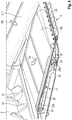
- Fig. 3 is a perspective view of a detail of the cutting mechanism 1 according to Fig. 1 shown with a modified component 19.
- the component 19 differs from that in the Fig. 2 shown component 14 characterized in that it has a roof-shaped surface 20, which is designed sloping to the outer longitudinal edges 15a and 15b.
- the cross-sectional profile of the modified component 19 is essentially triangular.
- the representation in Fig. 4 shows a perspective, partially sectioned partial view of a central portion of the cutting unit according to Fig. 1 , Shown in this view, only the one conveyor belt 13b. Because of the symmetrical structure of the conveying device 5, what is said below applies correspondingly to the conveyor belt 13a, not shown.
- the conveying device 5 comprises pairs of front and rear rollers 23a, 23b arranged in pairs and serving for the drive and the deflection, which surrounds the respective conveyor belt 13a, 13b.
- the rollers 23a, 23b each have an axis 24 which is rotatably mounted in both sides of the conveyor belt 13b arranged bearing points 25.
- the bearings 25 are disposed immediately adjacent to the conveyor belt 13b and the roller 23a, 23b.
- the respective bearing point 25 has a housing which encloses the conveyor belt 13b in sections in the deflection region of the roller 23a, 23b.
- the section of the housing of the bearing 25 enclosing the conveyor belt 13b in the circumferential direction serves as a scraper in order to avoid the entrainment of crop material by the conveyor belt 13b.
- a tensioning device 21 is provided with which the belt tension of the conveyor belt 13b can be adjusted or readjusted by a change in the distance of the rollers 23a, 23b.
- the function of the tensioning device 21 is based on a toggle lever arrangement.
- An operating lever 22 which is in Fig. 4 is shown in a locking position, the operation of the clamping device 21.
- the arrangement the tensioning device 21 is provided between the revolving conveyor belt 13b, which saves space.
- the actuating lever 22 protrudes laterally beyond an outer edge 26 of the conveyor belt 13b on the side facing the wedge-shaped component 14. In this case, the actuating lever 22 extends in the closed position parallel to the conveyor belt 13b.
- the component 14 can be disassembled.
- the thus exposed operating lever 22 is now actuated by an operator to re-tension the conveyor belt 13b.
- a further advantage results from the fact that the tensioning device 21 is built together with the respective conveyor belt 13a, 13b as a unit.
Landscapes
- Life Sciences & Earth Sciences (AREA)
- Environmental Sciences (AREA)
- Zoology (AREA)
- Apparatuses For Bulk Treatment Of Fruits And Vegetables And Apparatuses For Preparing Feeds (AREA)
- Structure Of Belt Conveyors (AREA)
- Threshing Machine Elements (AREA)
Applications Claiming Priority (1)
| Application Number | Priority Date | Filing Date | Title |
|---|---|---|---|
| DE102016118174.9A DE102016118174A1 (de) | 2016-09-26 | 2016-09-26 | Schneidwerk |
Publications (2)
| Publication Number | Publication Date |
|---|---|
| EP3298879A1 true EP3298879A1 (fr) | 2018-03-28 |
| EP3298879B1 EP3298879B1 (fr) | 2020-11-18 |
Family
ID=58638737
Family Applications (1)
| Application Number | Title | Priority Date | Filing Date |
|---|---|---|---|
| EP17168329.5A Active EP3298879B1 (fr) | 2016-09-26 | 2017-04-27 | Barre de coupe |
Country Status (6)
| Country | Link |
|---|---|
| US (1) | US10470370B2 (fr) |
| EP (1) | EP3298879B1 (fr) |
| AR (1) | AR108515A1 (fr) |
| BR (1) | BR102017014639B1 (fr) |
| DE (1) | DE102016118174A1 (fr) |
| HU (1) | HUE053365T2 (fr) |
Cited By (5)
| Publication number | Priority date | Publication date | Assignee | Title |
|---|---|---|---|---|
| EP3434095A1 (fr) * | 2017-07-27 | 2019-01-30 | Macdon Industries Ltd. | Tête pour machine de récolte |
| DE102018116213A1 (de) | 2018-07-04 | 2020-01-09 | CLAAS Hungária Kft. | Schneidwerk für eine landwirtschaftliche Arbeitsmaschine sowie Verfahren zu dessen Bedienung |
| DE102018116232A1 (de) | 2018-07-04 | 2020-01-09 | Claas Hungaria Kft. | Schneidwerk für eine landwirtschaftliche Arbeitsmaschine sowie Verfahren zur Einstellung eines Schneidwerks |
| US11445655B2 (en) | 2018-07-04 | 2022-09-20 | CLAAS Hungária Kft. | Cutting unit for an agricultural working machine, and method for adjusting a cutting unit |
| EP4356713A1 (fr) | 2022-10-20 | 2024-04-24 | Deere & Company | Tête de récolte pour récolte de plantes entières |
Families Citing this family (12)
| Publication number | Priority date | Publication date | Assignee | Title |
|---|---|---|---|---|
| CA3149508A1 (fr) * | 2017-02-24 | 2018-03-08 | IP Machinery Pty Ltd | Dispositif d'alimentation |
| US10537063B2 (en) | 2017-10-11 | 2020-01-21 | Deere & Company | Folding agricultural head |
| US10426088B2 (en) * | 2017-10-11 | 2019-10-01 | Deere & Company | Center feed assembly for a draper |
| US10433486B2 (en) | 2017-10-16 | 2019-10-08 | Deere & Company | System and method for wing float on a combine draper header |
| US10568266B2 (en) | 2017-10-17 | 2020-02-25 | Deere & Company | Self-contained combine draper wing leveler |
| US10820515B2 (en) * | 2018-06-28 | 2020-11-03 | Deere & Company | Combine header with feed assist bulky crop auger on a draper platform |
| EP3603375B1 (fr) * | 2018-07-31 | 2021-03-31 | CNH Industrial Belgium N.V. | Convoyeur à courroie d'alimentation au dispositif d'alimentation d'une moissonneuse-batteuse |
| DE102020121773A1 (de) | 2020-08-19 | 2022-02-24 | Claas Selbstfahrende Erntemaschinen Gmbh | Seitenschneidwerk |
| US12453312B2 (en) * | 2021-06-16 | 2025-10-28 | Deere & Company | Agricultural header with inter-belt crop divider |
| DE102022116765A1 (de) * | 2022-07-05 | 2024-01-11 | Claas Hungaria Kft. | Bandschneidwerk |
| US20250204324A1 (en) * | 2023-12-21 | 2025-06-26 | Agco Corporation | Draper Belt Tensioner System |
| DE102024119143A1 (de) * | 2024-07-05 | 2026-01-08 | Claas Selbstfahrende Erntemaschinen Gmbh | Fördereinrichtung zur Verwendung in einem Schneidwerk einer landwirtschaftlichen Erntemaschine sowie Schneidwerk und Erntemaschine |
Citations (4)
| Publication number | Priority date | Publication date | Assignee | Title |
|---|---|---|---|---|
| US5464371A (en) * | 1993-12-06 | 1995-11-07 | Honey Bee Manufacturing Ltd. | Feeder adapter for mounting a combine header to a feeder housing of a combine |
| US6817166B2 (en) | 2003-07-11 | 2004-11-16 | Macdon Industriesltd. | Crop feed draper for a header |
| US20080295474A1 (en) * | 2007-06-04 | 2008-12-04 | Claas Selbstfahrende Erntemaschinen Gmbh | Central auger crop feed system for a harvester |
| US7823372B1 (en) * | 2009-06-22 | 2010-11-02 | Deere & Company | Skewed roller conveyor for double windrow attachment |
Family Cites Families (18)
| Publication number | Priority date | Publication date | Assignee | Title |
|---|---|---|---|---|
| US2608041A (en) * | 1947-01-24 | 1952-08-26 | Case Co J I | Conveying means for harvester headers |
| US5822959A (en) * | 1996-05-06 | 1998-10-20 | Norton; R. Scott | Pick-up for harvesting a lying crop |
| US6202397B1 (en) * | 1999-05-27 | 2001-03-20 | Deere & Company | Draper belt tensioning mechanism for a harvesting platform |
| US6865871B2 (en) * | 2003-07-14 | 2005-03-15 | Macdon Industries Ltd. | Crop feed arrangement for the header of a combine harvester |
| US7392646B2 (en) * | 2004-06-16 | 2008-07-01 | Macdon Industries Ltd. | Reversible feed roller with radially extendible fingers |
| DE102005021766A1 (de) * | 2005-05-11 | 2006-11-16 | Deere & Company, Moline | Schneidwerk mit Fördergurtzusammenbauten |
| US20070193243A1 (en) * | 2006-02-10 | 2007-08-23 | Schmidt James R | Combine Harvester Draper Header Having Flexible Cutterbar |
| CA2564777C (fr) * | 2006-10-20 | 2010-08-03 | Macdon Industries Ltd. | Tete de moissonneuse-batteuse comportant un convoyeur a toile et un joint d'etancheite avec un element de la barre de coupe |
| CA2572274C (fr) * | 2006-12-29 | 2014-05-27 | Honey Bee Manufacturing Ltd. | Recepteur de roches pour bec cueilleur de moissonneuse-batteuse |
| US8281561B2 (en) * | 2010-08-17 | 2012-10-09 | Deere & Company | Flexible draper belt drive for an agricultural harvesting machine |
| DE102010037131A1 (de) * | 2010-08-24 | 2012-03-01 | Claas Selbstfahrende Erntemaschinen Gmbh | Schneidwerk |
| DE102013100322A1 (de) * | 2013-01-14 | 2014-07-17 | Claas Selbstfahrende Erntemaschinen Gmbh | Schneidwerk |
| DE102013103381A1 (de) * | 2013-04-04 | 2014-10-09 | Claas Selbstfahrende Erntemaschinen Gmbh | Schneidwerk |
| DE102014216112A1 (de) * | 2014-08-13 | 2016-02-18 | Walter Schmid | Selbstfahrende Erntemaschine |
| US9788486B2 (en) * | 2014-12-30 | 2017-10-17 | Agco Corporation | Grain header with swathing and chopping capability |
| US20160360699A1 (en) * | 2015-06-10 | 2016-12-15 | Jose Luis Allochis | Conveyor belt tensing apparatus for a harvesting header |
| DE102015118143A1 (de) * | 2015-10-23 | 2017-04-27 | Arnold Jäger Holding GmbH | Nockenriemen, insbesondere für landwirtschaftliche Maschinen |
| BE1023925B1 (nl) * | 2016-03-01 | 2017-09-13 | Cnh Industrial Belgium Nv | Toevoertoestel voor maaidorser |
-
2016
- 2016-09-26 DE DE102016118174.9A patent/DE102016118174A1/de not_active Withdrawn
-
2017
- 2017-04-27 HU HUE17168329A patent/HUE053365T2/hu unknown
- 2017-04-27 EP EP17168329.5A patent/EP3298879B1/fr active Active
- 2017-05-17 AR ARP170101333A patent/AR108515A1/es active IP Right Grant
- 2017-07-06 BR BR102017014639-1A patent/BR102017014639B1/pt active IP Right Grant
- 2017-08-08 US US15/671,726 patent/US10470370B2/en active Active
Patent Citations (4)
| Publication number | Priority date | Publication date | Assignee | Title |
|---|---|---|---|---|
| US5464371A (en) * | 1993-12-06 | 1995-11-07 | Honey Bee Manufacturing Ltd. | Feeder adapter for mounting a combine header to a feeder housing of a combine |
| US6817166B2 (en) | 2003-07-11 | 2004-11-16 | Macdon Industriesltd. | Crop feed draper for a header |
| US20080295474A1 (en) * | 2007-06-04 | 2008-12-04 | Claas Selbstfahrende Erntemaschinen Gmbh | Central auger crop feed system for a harvester |
| US7823372B1 (en) * | 2009-06-22 | 2010-11-02 | Deere & Company | Skewed roller conveyor for double windrow attachment |
Cited By (6)
| Publication number | Priority date | Publication date | Assignee | Title |
|---|---|---|---|---|
| EP3434095A1 (fr) * | 2017-07-27 | 2019-01-30 | Macdon Industries Ltd. | Tête pour machine de récolte |
| DE102018116213A1 (de) | 2018-07-04 | 2020-01-09 | CLAAS Hungária Kft. | Schneidwerk für eine landwirtschaftliche Arbeitsmaschine sowie Verfahren zu dessen Bedienung |
| DE102018116232A1 (de) | 2018-07-04 | 2020-01-09 | Claas Hungaria Kft. | Schneidwerk für eine landwirtschaftliche Arbeitsmaschine sowie Verfahren zur Einstellung eines Schneidwerks |
| US11445655B2 (en) | 2018-07-04 | 2022-09-20 | CLAAS Hungária Kft. | Cutting unit for an agricultural working machine, and method for adjusting a cutting unit |
| EP4356713A1 (fr) | 2022-10-20 | 2024-04-24 | Deere & Company | Tête de récolte pour récolte de plantes entières |
| DE102022127703A1 (de) | 2022-10-20 | 2024-04-25 | Deere & Company | Erntevorsatz zur Ganzpflanzenernte |
Also Published As
| Publication number | Publication date |
|---|---|
| HUE053365T2 (hu) | 2021-06-28 |
| AR108515A1 (es) | 2018-08-29 |
| BR102017014639A2 (pt) | 2018-04-10 |
| DE102016118174A1 (de) | 2018-03-29 |
| US20180084724A1 (en) | 2018-03-29 |
| US10470370B2 (en) | 2019-11-12 |
| BR102017014639B1 (pt) | 2022-03-29 |
| EP3298879B1 (fr) | 2020-11-18 |
Similar Documents
| Publication | Publication Date | Title |
|---|---|---|
| EP3298879B1 (fr) | Barre de coupe | |
| DE2848451C2 (fr) | ||
| DE2245602C2 (de) | Zwischen Mäh- und Dreschwerk eines Mähdreschers angeordnete Zuführungseinrichtung für Erntegut | |
| EP3406129B1 (fr) | Mécanisme de coupe | |
| EP1483955B1 (fr) | Appareil à récolter | |
| DE2536028B2 (de) | Erntevorrichtung für stengeiförmiges Halmgut | |
| DE1507195C3 (de) | Erntemaschine für stengeliges Halmgut, insbesondere Mais | |
| EP1305998A1 (fr) | Dispositif d'introduction et de cueillage | |
| DE10108516A1 (de) | Maschine zum Mähen von stängelartigem Erntegut | |
| DE10028887A1 (de) | Einzugs- und Pflückeinrichtung | |
| EP2786650A1 (fr) | Barre de coupe | |
| DE3115723C2 (de) | Vorsatzgerät für eine Maiserntemaschine | |
| EP1177718B1 (fr) | Machine pour faucher des plantes à tiges | |
| DE2735784A1 (de) | Reihen-schneidvorsatz fuer feldhaecksler | |
| EP2923556B1 (fr) | Appareil frontal pour une moissonneuse-batteuse auto-tractée destinée à la récolte de maïs | |
| DE102021112099A1 (de) | Korbsegment und Korb für einen Mähdrescher | |
| EP2430900B1 (fr) | Plateforme de coupe | |
| DE19750954A1 (de) | Aufnahmeeinrichtung einer landwirtschaftlichen Erntemaschine | |
| EP4074162B1 (fr) | Presse à balles rondes pourvue de rouleau de démarrage et d'élément de déviation pouvant être dévié élastiquement | |
| DE19952566C1 (de) | Erntegerät | |
| EP4309489B1 (fr) | Coupeuse de bande | |
| EP4305951B1 (fr) | Barre de coupe à tapis | |
| DE102008021784A1 (de) | Erntemaschine mit Schrägförderer | |
| EP4070642A1 (fr) | Appareil accessoire pour récolter des plantes sur tige doté d'une fente de cueillette située transversalement au sens de déplacement | |
| DE3324898A1 (de) | Schneid- und zufuehreinrichtung fuer eine gezogene oder fuer den dreipunktanbau am schlepper vorgesehene maschine zum ernten von mais o.dgl. stengelartigem erntegut |
Legal Events
| Date | Code | Title | Description |
|---|---|---|---|
| PUAI | Public reference made under article 153(3) epc to a published international application that has entered the european phase |
Free format text: ORIGINAL CODE: 0009012 |
|
| STAA | Information on the status of an ep patent application or granted ep patent |
Free format text: STATUS: THE APPLICATION HAS BEEN PUBLISHED |
|
| AK | Designated contracting states |
Kind code of ref document: A1 Designated state(s): AL AT BE BG CH CY CZ DE DK EE ES FI FR GB GR HR HU IE IS IT LI LT LU LV MC MK MT NL NO PL PT RO RS SE SI SK SM TR |
|
| AX | Request for extension of the european patent |
Extension state: BA ME |
|
| STAA | Information on the status of an ep patent application or granted ep patent |
Free format text: STATUS: REQUEST FOR EXAMINATION WAS MADE |
|
| 17P | Request for examination filed |
Effective date: 20180928 |
|
| RBV | Designated contracting states (corrected) |
Designated state(s): AL AT BE BG CH CY CZ DE DK EE ES FI FR GB GR HR HU IE IS IT LI LT LU LV MC MK MT NL NO PL PT RO RS SE SI SK SM TR |
|
| GRAP | Despatch of communication of intention to grant a patent |
Free format text: ORIGINAL CODE: EPIDOSNIGR1 |
|
| STAA | Information on the status of an ep patent application or granted ep patent |
Free format text: STATUS: GRANT OF PATENT IS INTENDED |
|
| INTG | Intention to grant announced |
Effective date: 20200825 |
|
| GRAS | Grant fee paid |
Free format text: ORIGINAL CODE: EPIDOSNIGR3 |
|
| GRAA | (expected) grant |
Free format text: ORIGINAL CODE: 0009210 |
|
| STAA | Information on the status of an ep patent application or granted ep patent |
Free format text: STATUS: THE PATENT HAS BEEN GRANTED |
|
| AK | Designated contracting states |
Kind code of ref document: B1 Designated state(s): AL AT BE BG CH CY CZ DE DK EE ES FI FR GB GR HR HU IE IS IT LI LT LU LV MC MK MT NL NO PL PT RO RS SE SI SK SM TR |
|
| REG | Reference to a national code |
Ref country code: GB Ref legal event code: FG4D Free format text: NOT ENGLISH |
|
| REG | Reference to a national code |
Ref country code: CH Ref legal event code: EP |
|
| REG | Reference to a national code |
Ref country code: IE Ref legal event code: FG4D Free format text: LANGUAGE OF EP DOCUMENT: GERMAN |
|
| REG | Reference to a national code |
Ref country code: DE Ref legal event code: R096 Ref document number: 502017008224 Country of ref document: DE |
|
| REG | Reference to a national code |
Ref country code: AT Ref legal event code: REF Ref document number: 1334726 Country of ref document: AT Kind code of ref document: T Effective date: 20201215 |
|
| REG | Reference to a national code |
Ref country code: NL Ref legal event code: MP Effective date: 20201118 |
|
| PG25 | Lapsed in a contracting state [announced via postgrant information from national office to epo] |
Ref country code: NO Free format text: LAPSE BECAUSE OF FAILURE TO SUBMIT A TRANSLATION OF THE DESCRIPTION OR TO PAY THE FEE WITHIN THE PRESCRIBED TIME-LIMIT Effective date: 20210218 Ref country code: RS Free format text: LAPSE BECAUSE OF FAILURE TO SUBMIT A TRANSLATION OF THE DESCRIPTION OR TO PAY THE FEE WITHIN THE PRESCRIBED TIME-LIMIT Effective date: 20201118 Ref country code: PT Free format text: LAPSE BECAUSE OF FAILURE TO SUBMIT A TRANSLATION OF THE DESCRIPTION OR TO PAY THE FEE WITHIN THE PRESCRIBED TIME-LIMIT Effective date: 20210318 Ref country code: FI Free format text: LAPSE BECAUSE OF FAILURE TO SUBMIT A TRANSLATION OF THE DESCRIPTION OR TO PAY THE FEE WITHIN THE PRESCRIBED TIME-LIMIT Effective date: 20201118 Ref country code: GR Free format text: LAPSE BECAUSE OF FAILURE TO SUBMIT A TRANSLATION OF THE DESCRIPTION OR TO PAY THE FEE WITHIN THE PRESCRIBED TIME-LIMIT Effective date: 20210219 |
|
| PG25 | Lapsed in a contracting state [announced via postgrant information from national office to epo] |
Ref country code: SE Free format text: LAPSE BECAUSE OF FAILURE TO SUBMIT A TRANSLATION OF THE DESCRIPTION OR TO PAY THE FEE WITHIN THE PRESCRIBED TIME-LIMIT Effective date: 20201118 Ref country code: BG Free format text: LAPSE BECAUSE OF FAILURE TO SUBMIT A TRANSLATION OF THE DESCRIPTION OR TO PAY THE FEE WITHIN THE PRESCRIBED TIME-LIMIT Effective date: 20210218 Ref country code: LV Free format text: LAPSE BECAUSE OF FAILURE TO SUBMIT A TRANSLATION OF THE DESCRIPTION OR TO PAY THE FEE WITHIN THE PRESCRIBED TIME-LIMIT Effective date: 20201118 Ref country code: IS Free format text: LAPSE BECAUSE OF FAILURE TO SUBMIT A TRANSLATION OF THE DESCRIPTION OR TO PAY THE FEE WITHIN THE PRESCRIBED TIME-LIMIT Effective date: 20210318 Ref country code: PL Free format text: LAPSE BECAUSE OF FAILURE TO SUBMIT A TRANSLATION OF THE DESCRIPTION OR TO PAY THE FEE WITHIN THE PRESCRIBED TIME-LIMIT Effective date: 20201118 |
|
| REG | Reference to a national code |
Ref country code: LT Ref legal event code: MG9D |
|
| REG | Reference to a national code |
Ref country code: HU Ref legal event code: AG4A Ref document number: E053365 Country of ref document: HU |
|
| PG25 | Lapsed in a contracting state [announced via postgrant information from national office to epo] |
Ref country code: HR Free format text: LAPSE BECAUSE OF FAILURE TO SUBMIT A TRANSLATION OF THE DESCRIPTION OR TO PAY THE FEE WITHIN THE PRESCRIBED TIME-LIMIT Effective date: 20201118 |
|
| PG25 | Lapsed in a contracting state [announced via postgrant information from national office to epo] |
Ref country code: RO Free format text: LAPSE BECAUSE OF FAILURE TO SUBMIT A TRANSLATION OF THE DESCRIPTION OR TO PAY THE FEE WITHIN THE PRESCRIBED TIME-LIMIT Effective date: 20201118 Ref country code: SK Free format text: LAPSE BECAUSE OF FAILURE TO SUBMIT A TRANSLATION OF THE DESCRIPTION OR TO PAY THE FEE WITHIN THE PRESCRIBED TIME-LIMIT Effective date: 20201118 Ref country code: SM Free format text: LAPSE BECAUSE OF FAILURE TO SUBMIT A TRANSLATION OF THE DESCRIPTION OR TO PAY THE FEE WITHIN THE PRESCRIBED TIME-LIMIT Effective date: 20201118 Ref country code: LT Free format text: LAPSE BECAUSE OF FAILURE TO SUBMIT A TRANSLATION OF THE DESCRIPTION OR TO PAY THE FEE WITHIN THE PRESCRIBED TIME-LIMIT Effective date: 20201118 Ref country code: EE Free format text: LAPSE BECAUSE OF FAILURE TO SUBMIT A TRANSLATION OF THE DESCRIPTION OR TO PAY THE FEE WITHIN THE PRESCRIBED TIME-LIMIT Effective date: 20201118 Ref country code: CZ Free format text: LAPSE BECAUSE OF FAILURE TO SUBMIT A TRANSLATION OF THE DESCRIPTION OR TO PAY THE FEE WITHIN THE PRESCRIBED TIME-LIMIT Effective date: 20201118 |
|
| REG | Reference to a national code |
Ref country code: DE Ref legal event code: R097 Ref document number: 502017008224 Country of ref document: DE |
|
| PG25 | Lapsed in a contracting state [announced via postgrant information from national office to epo] |
Ref country code: DK Free format text: LAPSE BECAUSE OF FAILURE TO SUBMIT A TRANSLATION OF THE DESCRIPTION OR TO PAY THE FEE WITHIN THE PRESCRIBED TIME-LIMIT Effective date: 20201118 |
|
| PLBE | No opposition filed within time limit |
Free format text: ORIGINAL CODE: 0009261 |
|
| STAA | Information on the status of an ep patent application or granted ep patent |
Free format text: STATUS: NO OPPOSITION FILED WITHIN TIME LIMIT |
|
| 26N | No opposition filed |
Effective date: 20210819 |
|
| PG25 | Lapsed in a contracting state [announced via postgrant information from national office to epo] |
Ref country code: NL Free format text: LAPSE BECAUSE OF FAILURE TO SUBMIT A TRANSLATION OF THE DESCRIPTION OR TO PAY THE FEE WITHIN THE PRESCRIBED TIME-LIMIT Effective date: 20201118 Ref country code: AL Free format text: LAPSE BECAUSE OF FAILURE TO SUBMIT A TRANSLATION OF THE DESCRIPTION OR TO PAY THE FEE WITHIN THE PRESCRIBED TIME-LIMIT Effective date: 20201118 |
|
| PG25 | Lapsed in a contracting state [announced via postgrant information from national office to epo] |
Ref country code: MC Free format text: LAPSE BECAUSE OF FAILURE TO SUBMIT A TRANSLATION OF THE DESCRIPTION OR TO PAY THE FEE WITHIN THE PRESCRIBED TIME-LIMIT Effective date: 20201118 Ref country code: SI Free format text: LAPSE BECAUSE OF FAILURE TO SUBMIT A TRANSLATION OF THE DESCRIPTION OR TO PAY THE FEE WITHIN THE PRESCRIBED TIME-LIMIT Effective date: 20201118 |
|
| GBPC | Gb: european patent ceased through non-payment of renewal fee |
Effective date: 20210427 |
|
| PG25 | Lapsed in a contracting state [announced via postgrant information from national office to epo] |
Ref country code: LU Free format text: LAPSE BECAUSE OF NON-PAYMENT OF DUE FEES Effective date: 20210427 |
|
| PG25 | Lapsed in a contracting state [announced via postgrant information from national office to epo] |
Ref country code: CH Free format text: LAPSE BECAUSE OF NON-PAYMENT OF DUE FEES Effective date: 20210430 Ref country code: LI Free format text: LAPSE BECAUSE OF NON-PAYMENT OF DUE FEES Effective date: 20210430 Ref country code: FR Free format text: LAPSE BECAUSE OF NON-PAYMENT OF DUE FEES Effective date: 20210430 Ref country code: GB Free format text: LAPSE BECAUSE OF NON-PAYMENT OF DUE FEES Effective date: 20210427 Ref country code: ES Free format text: LAPSE BECAUSE OF FAILURE TO SUBMIT A TRANSLATION OF THE DESCRIPTION OR TO PAY THE FEE WITHIN THE PRESCRIBED TIME-LIMIT Effective date: 20201118 |
|
| PG25 | Lapsed in a contracting state [announced via postgrant information from national office to epo] |
Ref country code: IE Free format text: LAPSE BECAUSE OF NON-PAYMENT OF DUE FEES Effective date: 20210427 |
|
| PG25 | Lapsed in a contracting state [announced via postgrant information from national office to epo] |
Ref country code: IS Free format text: LAPSE BECAUSE OF FAILURE TO SUBMIT A TRANSLATION OF THE DESCRIPTION OR TO PAY THE FEE WITHIN THE PRESCRIBED TIME-LIMIT Effective date: 20210318 |
|
| REG | Reference to a national code |
Ref country code: AT Ref legal event code: MM01 Ref document number: 1334726 Country of ref document: AT Kind code of ref document: T Effective date: 20220427 |
|
| P01 | Opt-out of the competence of the unified patent court (upc) registered |
Effective date: 20230516 |
|
| PG25 | Lapsed in a contracting state [announced via postgrant information from national office to epo] |
Ref country code: CY Free format text: LAPSE BECAUSE OF FAILURE TO SUBMIT A TRANSLATION OF THE DESCRIPTION OR TO PAY THE FEE WITHIN THE PRESCRIBED TIME-LIMIT Effective date: 20201118 |
|
| PG25 | Lapsed in a contracting state [announced via postgrant information from national office to epo] |
Ref country code: AT Free format text: LAPSE BECAUSE OF NON-PAYMENT OF DUE FEES Effective date: 20220427 |
|
| PG25 | Lapsed in a contracting state [announced via postgrant information from national office to epo] |
Ref country code: MK Free format text: LAPSE BECAUSE OF FAILURE TO SUBMIT A TRANSLATION OF THE DESCRIPTION OR TO PAY THE FEE WITHIN THE PRESCRIBED TIME-LIMIT Effective date: 20201118 |
|
| PG25 | Lapsed in a contracting state [announced via postgrant information from national office to epo] |
Ref country code: TR Free format text: LAPSE BECAUSE OF FAILURE TO SUBMIT A TRANSLATION OF THE DESCRIPTION OR TO PAY THE FEE WITHIN THE PRESCRIBED TIME-LIMIT Effective date: 20201118 |
|
| PG25 | Lapsed in a contracting state [announced via postgrant information from national office to epo] |
Ref country code: MT Free format text: LAPSE BECAUSE OF FAILURE TO SUBMIT A TRANSLATION OF THE DESCRIPTION OR TO PAY THE FEE WITHIN THE PRESCRIBED TIME-LIMIT Effective date: 20201118 |
|
| PGFP | Annual fee paid to national office [announced via postgrant information from national office to epo] |
Ref country code: DE Payment date: 20250422 Year of fee payment: 9 |
|
| PGFP | Annual fee paid to national office [announced via postgrant information from national office to epo] |
Ref country code: HU Payment date: 20250424 Year of fee payment: 9 |
|
| PGFP | Annual fee paid to national office [announced via postgrant information from national office to epo] |
Ref country code: IT Payment date: 20250424 Year of fee payment: 9 Ref country code: BE Payment date: 20250418 Year of fee payment: 9 |