EP3299090A1 - Dispositif de fabrication d'un profil à section transversale variable et profil à section transversale variable - Google Patents
Dispositif de fabrication d'un profil à section transversale variable et profil à section transversale variable Download PDFInfo
- Publication number
- EP3299090A1 EP3299090A1 EP17198635.9A EP17198635A EP3299090A1 EP 3299090 A1 EP3299090 A1 EP 3299090A1 EP 17198635 A EP17198635 A EP 17198635A EP 3299090 A1 EP3299090 A1 EP 3299090A1
- Authority
- EP
- European Patent Office
- Prior art keywords
- profile
- profiling
- metal strip
- profiling process
- semi
- Prior art date
- Legal status (The legal status is an assumption and is not a legal conclusion. Google has not performed a legal analysis and makes no representation as to the accuracy of the status listed.)
- Withdrawn
Links
- 238000000034 method Methods 0.000 claims abstract description 93
- 230000008569 process Effects 0.000 claims abstract description 70
- 239000002184 metal Substances 0.000 claims abstract description 45
- 238000003825 pressing Methods 0.000 claims description 9
- 238000005097 cold rolling Methods 0.000 claims description 8
- 238000004519 manufacturing process Methods 0.000 claims description 8
- 238000009966 trimming Methods 0.000 description 8
- 238000005096 rolling process Methods 0.000 description 6
- 239000000463 material Substances 0.000 description 5
- 239000007858 starting material Substances 0.000 description 5
- 230000009466 transformation Effects 0.000 description 5
- 230000008859 change Effects 0.000 description 4
- 238000004049 embossing Methods 0.000 description 4
- 229910000831 Steel Inorganic materials 0.000 description 2
- 238000005452 bending Methods 0.000 description 2
- 238000010924 continuous production Methods 0.000 description 2
- 238000005520 cutting process Methods 0.000 description 2
- 239000010959 steel Substances 0.000 description 2
- 230000007704 transition Effects 0.000 description 2
- 230000008901 benefit Effects 0.000 description 1
- 230000001419 dependent effect Effects 0.000 description 1
- 238000007688 edging Methods 0.000 description 1
- 239000002994 raw material Substances 0.000 description 1
- 230000000087 stabilizing effect Effects 0.000 description 1
Images


Classifications
-
- B—PERFORMING OPERATIONS; TRANSPORTING
- B21—MECHANICAL METAL-WORKING WITHOUT ESSENTIALLY REMOVING MATERIAL; PUNCHING METAL
- B21D—WORKING OR PROCESSING OF SHEET METAL OR METAL TUBES, RODS OR PROFILES WITHOUT ESSENTIALLY REMOVING MATERIAL; PUNCHING METAL
- B21D5/00—Bending sheet metal along straight lines, e.g. to form simple curves
- B21D5/06—Bending sheet metal along straight lines, e.g. to form simple curves by drawing procedure making use of dies or forming-rollers, e.g. making profiles
-
- B—PERFORMING OPERATIONS; TRANSPORTING
- B21—MECHANICAL METAL-WORKING WITHOUT ESSENTIALLY REMOVING MATERIAL; PUNCHING METAL
- B21D—WORKING OR PROCESSING OF SHEET METAL OR METAL TUBES, RODS OR PROFILES WITHOUT ESSENTIALLY REMOVING MATERIAL; PUNCHING METAL
- B21D22/00—Shaping without cutting, by stamping, spinning, or deep-drawing
- B21D22/02—Stamping using rigid devices or tools
-
- B—PERFORMING OPERATIONS; TRANSPORTING
- B21—MECHANICAL METAL-WORKING WITHOUT ESSENTIALLY REMOVING MATERIAL; PUNCHING METAL
- B21D—WORKING OR PROCESSING OF SHEET METAL OR METAL TUBES, RODS OR PROFILES WITHOUT ESSENTIALLY REMOVING MATERIAL; PUNCHING METAL
- B21D5/00—Bending sheet metal along straight lines, e.g. to form simple curves
- B21D5/06—Bending sheet metal along straight lines, e.g. to form simple curves by drawing procedure making use of dies or forming-rollers, e.g. making profiles
- B21D5/08—Bending sheet metal along straight lines, e.g. to form simple curves by drawing procedure making use of dies or forming-rollers, e.g. making profiles making use of forming-rollers
- B21D5/083—Bending sheet metal along straight lines, e.g. to form simple curves by drawing procedure making use of dies or forming-rollers, e.g. making profiles making use of forming-rollers for obtaining profiles with changing cross-sectional configuration
-
- B—PERFORMING OPERATIONS; TRANSPORTING
- B21—MECHANICAL METAL-WORKING WITHOUT ESSENTIALLY REMOVING MATERIAL; PUNCHING METAL
- B21D—WORKING OR PROCESSING OF SHEET METAL OR METAL TUBES, RODS OR PROFILES WITHOUT ESSENTIALLY REMOVING MATERIAL; PUNCHING METAL
- B21D53/00—Making other particular articles
-
- B—PERFORMING OPERATIONS; TRANSPORTING
- B21—MECHANICAL METAL-WORKING WITHOUT ESSENTIALLY REMOVING MATERIAL; PUNCHING METAL
- B21D—WORKING OR PROCESSING OF SHEET METAL OR METAL TUBES, RODS OR PROFILES WITHOUT ESSENTIALLY REMOVING MATERIAL; PUNCHING METAL
- B21D22/00—Shaping without cutting, by stamping, spinning, or deep-drawing
- B21D22/20—Deep-drawing
Definitions
- the present invention relates to a device for producing an elongate profile with a longitudinally varying cross-section, wherein the device is arranged for performing a method in which an elongated metal strip, which has two band edges profiled in a first profiling process to a semi-finished profile and then in a second profiling process is partially shaped such that at least two sections are offset from one another in a direction perpendicular to the longitudinal extent of the semi-finished profile.
- the invention also relates to an elongate profile made immediately after the process and to the process itself.
- profiles with varying cross section are required in various technical fields. For example, it is necessary to introduce a load into the profile at a certain point of the profile.
- the cross section of the profile must at this point or in adjacent areas u. U. be enlarged so that the profile is structurally suitable for receiving the loads. It may also be necessary for the cross-section to be reduced at a certain point, for example in order to attach a specific attachment to the profile at this point, or simply to make room for other components which need not necessarily be connected to the profile. which would otherwise collide with the profile.
- a prime example of the use of profiles with varying cross section is the automotive industry. It is not uncommon that certain carrier profiles for reasons of space at certain locations must have recesses, so that at this point, for example, cable guides or the like can be passed on the profile.
- a method for producing an elongated profile with varying cross section is for example out EP 1547922 B1 known.
- the method requires as starting material a sheet which has a special shape and is formed into a closed profile with a special roll profiling device in several steps.
- the roll forming system must be equipped with specially adjustable rollers. With the method, only continuous cross-sectional changes can be realized, a more or less erratic change in the cross section can not be generated.
- a method of the type mentioned is, for example EP 1344583 B1 known.
- this method first from a flat band by rolling a profiled band generated and then partially shaped such that at least two sections are offset in a direction perpendicular to the longitudinal extent of the belt against each other.
- the profiled strip is trimmed after embossing such that the staggered portions have a different cross-section.
- the reason for the production of the different cross sections is thus the last process step of trimming.
- Object of the present invention is to improve the device of the type mentioned and to avoid the problems mentioned.
- a solution according to the invention before the task if the device is set up such that the metal strip is trimmed prior to the first profiling process such that there is a longitudinal direction having varying width.
- the device according to the invention has the advantage that the metal strip can be trimmed at the beginning of the process in such a way that subsequent edging is no longer necessary.
- the trimming of the still unprofiled metal strip is particularly simple and can be done both in a punch press and in a rolling mill. It can be provided that a plurality of sections are offset from each other at regular intervals. For example, the finished profile can thereby obtain a tinned shape.
- the invention also provides a profile which is produced directly by the method for the implementation of which the device according to the invention is set up.
- the metal strip is trimmed in such a way that the strip edges run continuously straight after the second profiling process.
- a U-profile can be created with varying profile height, wherein the band edges at the opening side of the profile on a constant Level run.
- Continuously straight strip edges may also be desired if the strip edges are further processed, for example bent or rolled or also welded together, in a subsequent continuous process.
- the trimming of the metal strip must correspond to the offset. At a point where the finished profile has more material, the trimmed metal strip must also have a greater width than elsewhere.
- the metal strip is profiled in the first profiling process to form an open semi-finished profile.
- An open semi-finished profile can be in the second profiling process at the desired locations against each other, without causing warping or wrinkling. Overall, this simplifies the further process.
- the metal strip is profiled in the first profiling process to a U-profile.
- the U-profile is embossed in the second profiling process such that the at least two mutually offset portions are offset in a direction perpendicular to the bottom of the U-profile against each other.
- it is the bottom of the U-profile, which undergoes a level variation in the second profiling process and can be formed, for example staircase or crenellated.
- the metal strip can be profiled in the first profiling process, for example, to a pure V-profile or a V-profile with additionally angled, mutually parallel leg ends. The bottom of the profile is in this case V-shaped.
- the U-profile is reshaped into a hat profile after the second profiling process in a third profiling process by forming the legs of the U-profile or V Profiles are bent over in the area of their ends. If the trimming of the starting material, as described above, is carried out in such a way that the band edges run continuously straight after the second profiling process, this results in a hat profile with a constant width and varying profile height.
- the semi-finished profile is formed after the second profiling process in a third profiling process to form a closed hollow profile.
- the band edges are subsequently welded or soldered together, in particular in order to further increase the stability of the finished profile.
- the Final transformation to the closed hollow profile can be carried out, for example, in the cold rolling process.
- the first profiling process is carried out in the cold rolling process.
- this can be produced in a particularly simple manner in the first profiling a U-profile.
- the first profiling process can preferably take place in several profiling steps.
- it may be advantageous for the microstructure if a particularly pronounced change in shape, for example bending over 90 °, does not take place in one step but in several steps.
- the first profiling process in any pressing device, for example in a hydraulic press.
- several profiling steps can be provided. It is particularly advantageous if both the trimming step and the first profiling process are carried out in an intermittent method with a stamping press. This makes it possible to prefabricate even longer profiles quickly and inexpensively.
- the second profiling process also takes place in a pressing device, and thus in an intermittent, non-continuous process.
- this does not require a change or at least no further change to another profiling device.
- a press in particular in a deep-drawing press, a particularly large and, if desired, step-shaped offset can be generated.
- special rolls may preferably be provided with form-stamping elements on the outer circumference.
- the device according to the invention is particularly suitable for producing metal profiles from a flat, elongated metal strip.
- Preferably steel profiles are produced with the device according to the invention.
- the length of the profiles can be determined already at the beginning of the process by cutting to length a correspondingly long sheet metal strip, or after the actual profile production process by cutting to length the finished profiles.
- Fig. 1 shows an inventive elongated profile 1, which has been produced with the device according to the invention.
- the profile is a so-called hat profile, which essentially has the shape of a U-profile with outwardly bent legs 9.
- the profile has a plurality of sections 4 and 5, which are offset from each other perpendicular to the longitudinal extent of the profile.
- the staggered sections alternate each other in the longitudinal direction of the profile. More specifically, the portions 5 are offset outwardly from the intermediate portions 4 with respect to the bottom of the hat profile.
- the sections 5 are thus crenellated outward out.
- the outwardly bent legs 9 are not affected by the offset.
- the outer edges 3 of the hat profile are continuous straight.
- the profile is made of a simple elongated metal band, which is preferably made of steel.
- the elongated metal band is in Fig. 2 shown schematically and can be supplied to the device for producing the profile, for example via a reel, from which it is unrolled.
- the metal strip can be cut to a certain length before the actual profile production.
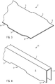
- the metal strip 2 is substantially straight, even the two band edges 3 of the metal strip are formed straight straight and parallel to each other.
- the metal strip is first trimmed, in such a way that it subsequently has a width which varies in the longitudinal direction.
- the trimming of the metal strip is preferably carried out in a conventional manner in a stamping press.
- the trimmed metal strip 2 is in Fig. 3 shown. It can be seen that the two band edges 3 now no longer run straight. Rather, recesses 6 are formed in sections in the band edges, which in the region of the sections 4 to be created later in FIG Fig. 1 shown profile lie.
- the shape of the transition between the recesses and the areas in which the band edge 3 remains un-trimmed depends largely on how exactly the transition between the staggered sections 4 and 5 should be designed.
- the trimmed metal strip 2 is formed in the next step to a simple U-profile.
- the resulting U-profile 10 is in Fig. 4 displayed.
- the U-profile has a continuous straight bottom 7, as well as two projecting at right angles from the ground leg 8.
- the transformation to the U-profile is preferably carried out in the line in the cold rolling process and may include several forming steps. In particular, if the metal strip has a very large material thickness, it is recommended that the legs 8 bend gradually.
- the transformation to the U-profile can of course also be done by means of another suitable pressing device. For example, it is possible to transform metal strips with low material thickness in a deep-drawing press to the U-profile.
- Fig. 1 shows staggered sections are generated.
- This profiling process can be done in several profiling steps, which is particularly necessary if two sections of the profile are to be particularly strongly offset from each other.
- the Versetz takes place preferably in a deep-drawing press.
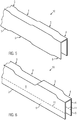
- Fig. 5 shows the U-profile 10 after a first deep-drawing process, in which initially a slight offset between the sections 4 and 5 is generated.
- the figure shows that the depth of the recesses 6 in the band edge 3 has already been reduced after the first deep-drawing operation.
- Fig. 6 the same U-profile is shown after another embossing process.
- the offset between the two sections 4 and 5 now already corresponds to the desired offset.
- the recesses 6 in the band edge 3 are now gone after the further offset of the profile.
- the band edges 3 are now again straight straight, just as in the starting material, namely the metal strip 2 Fig. 2 ,
- Fig. 7 shows a schematic representation of a pair of rollers 12/13 for generating the offset between the sections 4 and 5 in a rolling mill.
- the illustration shows both the pair of rollers and the still undeformed U-profile 10 each in longitudinal section.
- the offset in the profile interior sections 4 are generated by pressing the tread 7.
- the upper roller 12 of the roller pair has on its outer periphery to an outwardly projecting punch 15.
- the lower roller 13 has on the outer circumference via a recess 16, in which the punch 15 engages.
- the U-profile is stabilized during the embossing process by a plurality of roller pairs, not shown.
- the upper roller 12 of the pair of rollers shown has a stabilizing edge 14, with which the respective leg 8 of the U-profile is stabilized or held during the embossing process.
Landscapes
- Engineering & Computer Science (AREA)
- Mechanical Engineering (AREA)
- Metal Rolling (AREA)
- Bending Of Plates, Rods, And Pipes (AREA)
Applications Claiming Priority (2)
| Application Number | Priority Date | Filing Date | Title |
|---|---|---|---|
| DE102013018581.5A DE102013018581B4 (de) | 2013-11-05 | 2013-11-05 | Verfahren zur Herstellung eines Profils mit variierendem Querschnitt |
| EP14003646.8A EP2875877B1 (fr) | 2013-11-05 | 2014-10-28 | Procédé de fabrication d'un profilé à section variable |
Related Parent Applications (2)
| Application Number | Title | Priority Date | Filing Date |
|---|---|---|---|
| EP14003646.8A Division-Into EP2875877B1 (fr) | 2013-11-05 | 2014-10-28 | Procédé de fabrication d'un profilé à section variable |
| EP14003646.8A Division EP2875877B1 (fr) | 2013-11-05 | 2014-10-28 | Procédé de fabrication d'un profilé à section variable |
Publications (1)
| Publication Number | Publication Date |
|---|---|
| EP3299090A1 true EP3299090A1 (fr) | 2018-03-28 |
Family
ID=51867974
Family Applications (2)
| Application Number | Title | Priority Date | Filing Date |
|---|---|---|---|
| EP17198635.9A Withdrawn EP3299090A1 (fr) | 2013-11-05 | 2014-10-28 | Dispositif de fabrication d'un profil à section transversale variable et profil à section transversale variable |
| EP14003646.8A Active EP2875877B1 (fr) | 2013-11-05 | 2014-10-28 | Procédé de fabrication d'un profilé à section variable |
Family Applications After (1)
| Application Number | Title | Priority Date | Filing Date |
|---|---|---|---|
| EP14003646.8A Active EP2875877B1 (fr) | 2013-11-05 | 2014-10-28 | Procédé de fabrication d'un profilé à section variable |
Country Status (4)
| Country | Link |
|---|---|
| EP (2) | EP3299090A1 (fr) |
| DE (2) | DE102013018581B4 (fr) |
| DK (1) | DK2875877T3 (fr) |
| ES (1) | ES2675794T3 (fr) |
Families Citing this family (1)
| Publication number | Priority date | Publication date | Assignee | Title |
|---|---|---|---|---|
| PL3034191T5 (pl) † | 2014-12-19 | 2022-05-23 | Voestalpine Krems Gmbh | Urządzenie i sposób do wytwarzania podłużnej części profilowej |
Citations (6)
| Publication number | Priority date | Publication date | Assignee | Title |
|---|---|---|---|---|
| JPS6233019A (ja) * | 1985-08-02 | 1987-02-13 | Nissan Motor Co Ltd | プレス成形方法およびプレス成形装置 |
| EP0363232A1 (fr) * | 1988-08-29 | 1990-04-11 | Tecphy | Procédé de réalisation d'une pièce de structure à haute résistance mécanique |
| EP1344583A1 (fr) * | 2002-03-12 | 2003-09-17 | Kronenberg Profil GmbH | Profilé, dispositif et procédé pour sa production et utilisation de ce profilé |
| EP1537922A1 (fr) * | 2003-12-04 | 2005-06-08 | HONDA MOTOR CO., Ltd. | Fabrication de profilés avec une section variable dans la direction longitudinale |
| EP1997570A2 (fr) * | 2007-05-31 | 2008-12-03 | Nissan Motor Co., Ltd. | Produit formé par presse et son procédé de fabrication |
| EP1547922B1 (fr) | 2003-12-22 | 2009-02-25 | Calzoni S.r.l. | Dispositif optique indiquant l'angle de plané pour un aéronef |
Family Cites Families (2)
| Publication number | Priority date | Publication date | Assignee | Title |
|---|---|---|---|---|
| DE10350776A1 (de) * | 2003-10-30 | 2005-06-09 | Daimlerchrysler Ag | Bauteil mit in seinem Längsverlauf sich änderndem Profilquerschnitt |
| JP2008189126A (ja) * | 2007-02-05 | 2008-08-21 | Kobe Steel Ltd | 構造用部材 |
-
2013
- 2013-11-05 DE DE102013018581.5A patent/DE102013018581B4/de not_active Expired - Fee Related
- 2013-11-05 DE DE202013012608.6U patent/DE202013012608U1/de not_active Expired - Lifetime
-
2014
- 2014-10-28 EP EP17198635.9A patent/EP3299090A1/fr not_active Withdrawn
- 2014-10-28 ES ES14003646.8T patent/ES2675794T3/es active Active
- 2014-10-28 DK DK14003646.8T patent/DK2875877T3/en active
- 2014-10-28 EP EP14003646.8A patent/EP2875877B1/fr active Active
Patent Citations (7)
| Publication number | Priority date | Publication date | Assignee | Title |
|---|---|---|---|---|
| JPS6233019A (ja) * | 1985-08-02 | 1987-02-13 | Nissan Motor Co Ltd | プレス成形方法およびプレス成形装置 |
| EP0363232A1 (fr) * | 1988-08-29 | 1990-04-11 | Tecphy | Procédé de réalisation d'une pièce de structure à haute résistance mécanique |
| EP1344583A1 (fr) * | 2002-03-12 | 2003-09-17 | Kronenberg Profil GmbH | Profilé, dispositif et procédé pour sa production et utilisation de ce profilé |
| EP1344583B1 (fr) | 2002-03-12 | 2004-06-16 | Kronenberg Profil GmbH | Dispositif et procédé pour la production d'un profilé allongé |
| EP1537922A1 (fr) * | 2003-12-04 | 2005-06-08 | HONDA MOTOR CO., Ltd. | Fabrication de profilés avec une section variable dans la direction longitudinale |
| EP1547922B1 (fr) | 2003-12-22 | 2009-02-25 | Calzoni S.r.l. | Dispositif optique indiquant l'angle de plané pour un aéronef |
| EP1997570A2 (fr) * | 2007-05-31 | 2008-12-03 | Nissan Motor Co., Ltd. | Produit formé par presse et son procédé de fabrication |
Also Published As
| Publication number | Publication date |
|---|---|
| DK2875877T3 (en) | 2018-07-16 |
| EP2875877A1 (fr) | 2015-05-27 |
| DE102013018581B4 (de) | 2019-02-21 |
| ES2675794T3 (es) | 2018-07-12 |
| DE102013018581A1 (de) | 2015-05-07 |
| DE202013012608U1 (de) | 2017-11-21 |
| EP2875877B1 (fr) | 2018-04-25 |
Similar Documents
| Publication | Publication Date | Title |
|---|---|---|
| EP2313216B1 (fr) | Procédé de fabrication d'un profilé laminé à froid présentant au moins un bord profilé épaissi | |
| EP2085163B1 (fr) | Procédé de profilage à froid pour la production d'un profilé | |
| DE10041280C2 (de) | Verfahren und Vorrichtung zum flexiblen Walzen eines Metallbandes | |
| DE2549072B2 (de) | Vorrichtung zur Herstellung von Durchbrüchen in Bandmaterial aus Metallblech | |
| DE10113610C2 (de) | Verfahren und Walzvorrichtung zur Ausbildung von dickenprofiliertem einstückigem Walzgut | |
| DE102009008356B4 (de) | Verfahren zur Herstellung von profilierten Blechen | |
| DE102007051354B4 (de) | Verfahren zum Herstellen eines Profils aus flachem Metallband | |
| AT512899B1 (de) | Verfahren zur Herstellung eines Blechprofils für eine Schubladen-Ausziehführung | |
| EP2875877B1 (fr) | Procédé de fabrication d'un profilé à section variable | |
| EP2025420B1 (fr) | Procédé d'amincissement de laminage d'une seule pièce | |
| DE19818234A1 (de) | Rollprofiliereinrichtung zur Herstellung von Roll- oder Walzprofilelementen | |
| DE102014201611A1 (de) | Bidirektionale Tailored Rolled Platine | |
| DE102009056324A1 (de) | Verfahren und Vorrichtung zum Längsumformen eines Metallbands mit entlang seiner Längsachse variierender Materialstärke | |
| EP1847334A1 (fr) | Méthode de réduction d'épaisseur d'un materiau roulé | |
| DE10210807A1 (de) | Profilteil, Vorrichtung und Verfahren zu seiner Herstellung sowie Verwendung des Profilteils | |
| DE102007045644A1 (de) | Vorrichtung und Verfahren zum Umformen eines Bauteils aus blechförmigem Material mittels Rollprofilieren | |
| EP1847333A1 (fr) | Méthode de réduction d'épaisseur d'un materiau roulé | |
| EP2959985B1 (fr) | Poutre profilée en feuillard laminé à froid ayant une résistance à la flexion accrue et son procédé de production | |
| EP2208555B1 (fr) | Procédé de laminage et dispositif de laminage pour la fabrication d'une bande de métal ayant une épaisseur variant en largeur | |
| DE102009056514A1 (de) | Walzverfahren und Walzvorrichtung zum Herstellen eines Metallbandes mit einer über seine Breite variierenden Dicke | |
| AT201018B (de) | Verfahren und Vorrichtung zur Herstellung von im Querschnitt doppeltkonischen Metallbändern durch Kaltwalzen | |
| EP3515629B1 (fr) | Procédé et dispositif pour élargir un élément métallique | |
| DE102010034045B4 (de) | Verfahren zur Herstellung eines hülsenartigen Distanzelements und Anordnung zur Durchführung des Verfahrens | |
| DE102007034079B4 (de) | Profilschiene für den Höhenversteller eines Beschlagteils eines Sicherheitsgurtsystems und Verfahren zur Herstellung einer Profilschiene für den Höhenversteller eines Beschlagteils eines Sicherheitsgurtsystems | |
| EP2301688A1 (fr) | Dispositif de laminage pour la fabrication d'une bande de métal ou d'un profilé ayant une épaisseur variant en largeur |
Legal Events
| Date | Code | Title | Description |
|---|---|---|---|
| PUAI | Public reference made under article 153(3) epc to a published international application that has entered the european phase |
Free format text: ORIGINAL CODE: 0009012 |
|
| AC | Divisional application: reference to earlier application |
Ref document number: 2875877 Country of ref document: EP Kind code of ref document: P |
|
| AK | Designated contracting states |
Kind code of ref document: A1 Designated state(s): AL AT BE BG CH CY CZ DE DK EE ES FI FR GB GR HR HU IE IS IT LI LT LU LV MC MK MT NL NO PL PT RO RS SE SI SK SM TR |
|
| STAA | Information on the status of an ep patent application or granted ep patent |
Free format text: STATUS: THE APPLICATION IS DEEMED TO BE WITHDRAWN |
|
| 18D | Application deemed to be withdrawn |
Effective date: 20180929 |