EP3299213B1 - Dispositif de detachement de siege de vehicule, dispositif de butee de siege de vehicule et siege de vehicule - Google Patents
Dispositif de detachement de siege de vehicule, dispositif de butee de siege de vehicule et siege de vehicule Download PDFInfo
- Publication number
- EP3299213B1 EP3299213B1 EP16190697.9A EP16190697A EP3299213B1 EP 3299213 B1 EP3299213 B1 EP 3299213B1 EP 16190697 A EP16190697 A EP 16190697A EP 3299213 B1 EP3299213 B1 EP 3299213B1
- Authority
- EP
- European Patent Office
- Prior art keywords
- vehicle seat
- locking
- piston
- locking element
- unlocking device
- Prior art date
- Legal status (The legal status is an assumption and is not a legal conclusion. Google has not performed a legal analysis and makes no representation as to the accuracy of the status listed.)
- Active
Links
Images




Classifications
-
- B—PERFORMING OPERATIONS; TRANSPORTING
- B60—VEHICLES IN GENERAL
- B60N—SEATS SPECIALLY ADAPTED FOR VEHICLES; VEHICLE PASSENGER ACCOMMODATION NOT OTHERWISE PROVIDED FOR
- B60N2/00—Seats specially adapted for vehicles; Arrangement or mounting of seats in vehicles
- B60N2/02—Seats specially adapted for vehicles; Arrangement or mounting of seats in vehicles the seat or part thereof being movable, e.g. adjustable
- B60N2/22—Seats specially adapted for vehicles; Arrangement or mounting of seats in vehicles the seat or part thereof being movable, e.g. adjustable the back-rest being adjustable
- B60N2/224—Stepwise movement mechanisms, e.g. ratchets
-
- B—PERFORMING OPERATIONS; TRANSPORTING
- B60—VEHICLES IN GENERAL
- B60N—SEATS SPECIALLY ADAPTED FOR VEHICLES; VEHICLE PASSENGER ACCOMMODATION NOT OTHERWISE PROVIDED FOR
- B60N2/00—Seats specially adapted for vehicles; Arrangement or mounting of seats in vehicles
- B60N2/02—Seats specially adapted for vehicles; Arrangement or mounting of seats in vehicles the seat or part thereof being movable, e.g. adjustable
- B60N2/20—Seats specially adapted for vehicles; Arrangement or mounting of seats in vehicles the seat or part thereof being movable, e.g. adjustable the back-rest being tiltable, e.g. to permit easy access
- B60N2/206—Seats specially adapted for vehicles; Arrangement or mounting of seats in vehicles the seat or part thereof being movable, e.g. adjustable the back-rest being tiltable, e.g. to permit easy access to a position in which it can be used as a support for objects, e.g. as a tray
-
- F—MECHANICAL ENGINEERING; LIGHTING; HEATING; WEAPONS; BLASTING
- F16—ENGINEERING ELEMENTS AND UNITS; GENERAL MEASURES FOR PRODUCING AND MAINTAINING EFFECTIVE FUNCTIONING OF MACHINES OR INSTALLATIONS; THERMAL INSULATION IN GENERAL
- F16C—SHAFTS; FLEXIBLE SHAFTS; ELEMENTS OR CRANKSHAFT MECHANISMS; ROTARY BODIES OTHER THAN GEARING ELEMENTS; BEARINGS
- F16C1/00—Flexible shafts; Mechanical means for transmitting movement in a flexible sheathing
- F16C1/10—Means for transmitting linear movement in a flexible sheathing, e.g. "Bowden-mechanisms"
-
- F—MECHANICAL ENGINEERING; LIGHTING; HEATING; WEAPONS; BLASTING
- F16—ENGINEERING ELEMENTS AND UNITS; GENERAL MEASURES FOR PRODUCING AND MAINTAINING EFFECTIVE FUNCTIONING OF MACHINES OR INSTALLATIONS; THERMAL INSULATION IN GENERAL
- F16C—SHAFTS; FLEXIBLE SHAFTS; ELEMENTS OR CRANKSHAFT MECHANISMS; ROTARY BODIES OTHER THAN GEARING ELEMENTS; BEARINGS
- F16C2326/00—Articles relating to transporting
- F16C2326/01—Parts of vehicles in general
- F16C2326/08—Vehicle seats, e.g. in linear movable seats
Definitions
- the invention relates to a vehicle seat release device.
- the vehicle seat release device can solve a locking device of a vehicle seat to adjust this, or lock again to secure the vehicle seat against adjustment.
- Vehicle seats can be adjusted in many ways: To be able to adjust a vehicle seat particularly well to its user, vehicle seats are usually displaced so that, for example, a distance between the vehicle seat and steering wheel or pedals can be adjusted individually.
- the backrests of vehicle seats are often pivotable. As a result, on the one hand, the backrest can be brought into a comfortable angle for the user of the vehicle seat to a seat part of the vehicle seat, but also the angle of the backrest to the seat part can be changed according to the situation. For example, the backrest can be reclined when the user wants to stretch out in a driving break. But it can also be provided that the backrest is folded as far forward as possible in the direction of the seat part of the vehicle seat.
- the vehicle seat is not intended to obstruct a path, for example to get into a vehicle or into a cabin of a commercial vehicle or to create extra space in a cabin of a commercial vehicle.
- the vehicle seat can then be moved to its forwardmost position and the backrest folded as far forward as possible.
- the vehicle seat may be adjustable in height or in a rotation angle about the vertical axis. Other adjustment possibilities of the vehicle seat are possible. Against an adjustment of the vehicle seat must be lockable and be solvable to the desired adjustment.
- a locking device of a vehicle seat for an adjustment and lock again after the adjustment.
- the locking of the vehicle seat against an adjustment via a locking device which is often a lock.
- a locking device which is often a lock.
- Such locking devices are located for mechanical reasons normally near the axis about which the adjustment is made, or a movable in the adjustment part of the vehicle seat.
- the locking device is against the pivoting of the backrest in the example described in the region of the axis about which the backrest is pivoted.
- a manual actuating device with which the locking device can be actuated, can be located in the region of the locking device.
- the manual actuating device can also be arranged at a distance from the locking device.
- a hand lever is often provided for releasing the lock for the pivoting of the backrest, which is arranged in an upper region of the backrest. The movement of the hand lever is mechanically transmitted to the locking device, for example by a Bowden cable.
- the locking element is released by operating the hand lever, for example, the locking pawl released from engagement with the locking wheel. Due to the direct mechanical coupling of the user who wants to adjust the vehicle seat, to release the lock must apply a hand force sufficient for (mechanical) release of the locking device.
- Vehicle seats in which a lock is released by a hand applied to a manual actuator hand force is transmitted via a Bowden cable, for example, from the German utility models DE 20 2014 104 868 U1 .
- the publication DE 10 2004 050 773 A1 discloses a vehicle seat having a seat portion and a seat back.
- the seat part and the backrest are each mounted independently of each other about a vehicle transverse axis pivotable on a frame.
- a locking of the pivot positions of the seat part and the backrest is carried out in each case via a Locking device.
- the two locking devices can be released against the application of a spring by a Bowden cable to allow pivoting of the seat part and / or the backrest as needed.
- the forces to release the locking devices must be applied manually by the user, which can be done by manual operation of a handle.
- the locking device of the seat part is released by pivoting the backrest on the mechanically coupled to the backrest Bowden cable.
- the publication DE 20 2006 008 821 U1 describes various embodiments of a vehicle seat adjustment with a planetary gear, the sun gear is coupled to an electric drive, while the planet carrier is coupled to a seat member of a vehicle seat.
- a ring gear of the planetary gear is fixed so that an electrical adjustment of the seat element of the vehicle seat is possible by operation of the electric drive.
- a manual adjustment of the seat element of the vehicle seat a release of the locking device of the ring gear is required, which can be achieved when fixed on the electric drive or braked sun gear free movement of the planet carrier mounted on the planet with the Ring gear and thus a free manual pivoting of the seat element is possible.
- the release of the locking device of the ring gear via a manual pivoting of a hand lever, which is arranged in the upper region of a seat back.
- the hand lever is mechanically coupled via a Bowden cable with the locking device of the ring gear.
- the invention has for its object to provide a vehicle seat release device that allows release of a locking device of a vehicle seat in consideration of the space conditions and / or the ease of use. Furthermore, the invention has the object on which to propose a correspondingly improved vehicle seat lock. Finally, the invention is dedicated to an improvement of a vehicle seat.
- the invention relates to a vehicle seat release device with a control unit, a Bowden cable and a locking element, which are connected in mechanical series connection with each other.
- the vehicle seat release device is used for releasing, so unlocking, a vehicle seat, so that an adjustment of the vehicle seat is possible.
- the adjustment may be a displacement of the vehicle seat, a pivoting of a backrest of the vehicle seat, a height adjustment of the vehicle seat, a rotation of the vehicle seat about the vertical axis or otherwise adjusting the vehicle seat or any other adjustment or even a combination of different adjustments ,
- the locking element may directly be itself part of a locking device of the vehicle seat.
- it may be a locking pawl, which engages in a locking element and locks during its engagement the vehicle seat against an adjustment.
- the locking element may also be a transmission element, which is not itself part of the locking device, but is mechanically coupled to an element of the locking device.
- locking element and element of the locking device may be firmly connected to each other, but also, for example, be coupled together so that a movement of the locking element is transmitted to the element of the locking device, but a movement of the element of the locking device is not transmitted to the locking element, or so, that a transfer takes place only for partial movements of one of the two elements.
- the locking element may also be part of a transmission gear or be coupled to a transmission gear that drives the element of the locking device.
- This may preferably be a locking or latching, but also, for example, a frictional locking.
- a locking force that actuates the locking element and thus the locking device is generated by the actuator and transmitted via the Bowden cable to the locking element.
- the actuator is in particular a control unit, which is not driven by a manual force of a user, but via an external power source, ie operated with external energy.
- Utilization of the external power source for operating the vehicle seat release device is particularly advantageous, as not (manually) by the user must be applied the (hand) force for causing the movement of the locking element, but at least partially from the external power source is applied.
- the Bowden cable is (directly or indirectly) coupled at one end to the actuator, that the actuation of the actuator actuates the Bowden cable.
- the Bowden cable can be operated on pressure.
- the Bowden cable is operated (alone or also) on train, since Bowden cables are designed especially for the effective transmission of tensile forces.
- the Bowden cable is at its other end (directly or indirectly) mechanically coupled to the locking element, so that the force applied by the external energy source locking force is transmitted from the actuator to the locking element.
- the Bowden cable is a flexible power transmission element, which can transmit the locking force over any distances and arbitrary routes to be selected, especially around curves.
- the control unit can be provided in any position relative to the locking element. It is not necessary that actuator and locking element are in the immediate vicinity or that the power transmission between them must be done, for example, in a straight line way. This means that the actuator can be mounted on the vehicle seat at any point. This is particularly advantageous because it allows a particularly good use of space.
- the control unit can, for example, outside the vehicle seat or in or on the backrest of the vehicle seat or otherwise be mounted in or on the vehicle seat or a seat console at a position at which the other construction of the vehicle seat so permits.
- the power transmission from the actuator to the locking element is done exclusively by the Bowden cable, which can form a self-contained force system. On the other hand protects the shell of the Bowden cable arranged therein soul on the means of the Bowden bridged transmission path.
- the control unit can be an electrically operated positioning unit, so that the external energy source can be, for example, a battery, an accumulator or a generator.
- the actuator is a pneumatic actuator.
- the external power source is a compressed air source or supply.
- a pneumatic compressed air supply which can then be used in the context of the invention for the vehicle seat release device.
- This may be a general compressed air supply for the vehicle, for example, for brakes and / or suspension, but also for a door opening, a vehicle seat suspension, a cabin suspension or a mirror adjustment, where appropriate, the compressed air supply supplies several consumer circuits and Mauroisernike with compressed air.
- it can also be a local compressed air supply, which is used anyway and exclusively for the vehicle seat, for example.
- a suspension of the vehicle seat or more vehicle seats In this case can serve as a compressed air source and a compressor which is part of or a vehicle seat.
- the user operates in any way the actuator, for example by closing or switching over an electrical or pneumatic circuit via a switch.
- the actuator is a pneumatic actuator
- the pneumatic actuator can be actuated via a manually operated valve unit.
- the valve unit may have one or more valves. If “the valve” is described in more detail below, it may also be one of a plurality of valves of the valve unit, wherein the plurality of valves may be the same or different.
- the valve may be a valve of any type having any positions and connections. In particular, it may be a slide valve or a poppet valve or poppet valve.
- the valve unit can be manually operated in any manner.
- the valve unit may be actuated via a manual actuator such as a push button or pull knob, a switch, a lever, a tap, or otherwise.
- a manual actuator such as a push button or pull knob, a switch, a lever, a tap, or otherwise.
- the valve unit can be operated directly mechanically, or the manual operation is carried out electrically, wherein a valve position is changed by an electromagnet, which is electrically actuated by the manual operation.
- the manual actuator can therefore also be so mechanically or electrically connected to other components of the valve unit as in particular the valve or the valves, that the manual actuator can be arranged spaced from parts or all of the other components.
- valve unit or at least the manual actuator may be positioned in an easily accessible location on the vehicle seat or in the vicinity of the vehicle seat.
- valve unit or at least the manual actuating element can be positioned approximately at an upper side of the vehicle seat or in a side area of the vehicle seat, preferably in an upper side area of the vehicle seat.
- valve unit expended for the manual operation force By manual operation of the valve unit expended for the manual operation force is decoupled from the required locking force.
- the valve unit only has to be in pneumatic communication with the pneumatic actuator.
- the actuator can still be attached to a different advantageous position, in particular within the vehicle seat.
- valve or valves and actuator When the manual operation is not performed directly on the valve or the valves, but via a spaced-apart manual actuator, this also applies to the valve or the valves, wherein valve or valves and actuator not necessarily have to be positioned together, but can be arranged at a distance. But it is entirely possible that the valve unit and the pneumatic actuator are arranged immediately adjacent to each other, fastened to each other or are flanged or integrated into a structural unit.
- the British patent application GB 11972 discloses a transmission of a movement of a hydraulic pressure piston on a pressure gauge by means of a Bowden cable.
- the known generation of an actuating force via a fluidic control unit and its transmission by means of a Bowden cable to an element to be actuated is first transmitted to a vehicle seat with the particular installation space requirements prevailing there.
- the Bowden cable on a soul and a shell This corresponds basically to a normal design of a Bowden cable.
- the locking element is then mechanically coupled to a first end region of the core.
- the control unit has a pneumatically actuated piston and a cylinder housing, wherein the piston can be brought into a first working position and into a second working position, depending on the pneumatic loading in the cylinder housing.
- the soul of the Bowden cable is mechanically coupled to the piston in a second end region, so that depending on the pneumatic actuation of the actuator as a result of movement of the piston from the first working position to the second working position, the locking element can be brought into the release position.
- the piston assumes the first working position when the pneumatic actuator is vented, and the second working position occupies when the pneumatic actuator is vented.
- the piston assumes the first working position when the pneumatic actuator is vented, and occupies the second working position when the pneumatic actuator is vented.
- the locking element is brought into the release position when the pneumatic actuator is vented.
- ventilation of the pneumatic control unit is only necessary if the locking element is to be brought into the release position and held there, ie if an adjustment of the vehicle seat should be possible.
- This is advantageous because an adjustment of the vehicle seat in a total period of use of the vehicle seat will have a much lower proportion of time than the use of the vehicle seat without making any adjustment.
- adjusting the vehicle seat is a time-limited intervention. It is therefore effective to combine this intervention with the energetically more complex state, ie the ventilation of the pneumatic control unit.
- the core of the Bowden cable can have a coupling element in the second end region coupled to the piston, and the piston can have a piston rod on which a receptacle is held in which the coupling element is received such that the coupling element acts at least on tensile forces acting on the core is supported in the longitudinal direction of the piston rod on the receptacle.
- the coupling element can in particular be pressed onto the soul. But it can also be integrally formed with the soul or cohesively or via a screw or a pin or otherwise positively connected to the soul.
- the coupling element may for example be cylindrical or cuboid, in particular cubic. In particular, the coupling element may be spherical.
- the recording can completely enclose the coupling element, the soul is passed only through a recess of the recording.
- the receptacle can also be formed on one or more sides of the coupling element open or in the manner of a cage.
- the recess through which the soul is guided into the receptacle be open-edge. In this way, the soul with the coupling element can be easily pushed into the receptacle.
- the receptacle can also be designed in two parts.
- the receptacle can form a ball joint with the coupling element.
- the recording can completely or partially enclose the ball.
- the ball is thus rotatable in the ball joint.
- the soul is not loaded in the longitudinal direction of the piston rod to train, but tensile forces act at an angle to the longitudinal direction, the power transmission between the ball joint and thus the piston on one side and the ball and thus the soul on the other Page anyway ideal, since the ball and the ball joint continue to rest against each other with the entire or at least a substantial part of the loaded ball surface and by means of the ball joint and different angular positions between the soul and ball on the one hand and the recording on the other.
- the pneumatic control unit is a double-acting actuator, d. H. has two pneumatic connections, so that the piston can be moved by pneumatic loading either on its one or the other side between the working positions.
- the pneumatic actuator may have a return spring, with which a provision of the piston from the second operating position is at least supported in the first working position. This may in particular be the case if the pneumatic actuator has only one pneumatic connection, so that the pneumatic actuator can only be either vented or vented. In this case can be brought by the ventilation of the piston from the first working position to the second working position and reset by the return spring of the piston from the second working position to the first working position.
- the return spring is arranged on a side facing away from a piston rod side of the piston. If there is a pneumatic connection of the pneumatic actuator on the side of the piston with the piston rod, the return spring may be a compression spring. Conversely, if the piston rod facing away from the side of the piston can be pneumatically acted upon, the return spring may be a tension spring.
- the return spring may be arranged at least partially in a recess of the piston rod and / or the piston. How far the return spring is arranged in the recess, may be dependent on the position of the piston. For example, the return spring may be disposed entirely within the recess when the piston is in its one end position, which may then even abut against a first wall of the cylinder housing. The further the piston moves from this first end position in the direction of its second end position, in which it can rest against a second wall of the cylinder housing, the farther the return spring will emerge from the recess. In this case, the first end position of the first working position or the second working position and the second end position of the second working position or the first working position of the piston correspond. This depends on a mechanical coupling between the actuator and Bowden cable, Bowden cable and locking element and locking element and locking device, and a mode of action of Locking device and the control unit. The inventive measures a particularly compact design of the vehicle seat release device can be created.
- the valve unit may be a 3/2-way valve or have a 3/2-way valve.
- a 3/2-way valve has a ventilation position and a venting position. If the 3/2-way valve is in its vent position, the pneumatic actuator is also vented. This may represent a normal state of the vehicle seat release device in which the vehicle seat release device is most of the time, namely whenever no adjustment of the vehicle seat is to be made.
- the 3/2-way valve can be brought into the ventilation position, whereby the pneumatic actuator is also ventilated.
- venting is the exception that is needed only when the vehicle seat is to be adjusted.
- 3/2-way valves are standard valves that can be manufactured or purchased at low cost.
- the valve unit and the pneumatic control unit can be pneumatically coupled and the soul of the Bowden cable and the locking element mechanically coupled so that upon actuation of the valve unit, the locking element is brought into the release position and is brought to a release of the actuating element, the locking element in the locked position ,
- This may mean, for example, the following chain of action:
- the valve unit is actuated, so that the pneumatic actuator is vented.
- the venting of the pneumatic control unit causes the piston is brought into the first working position.
- the soul of the Bowden cable is operated on train, so that the locking element is brought into the release position.
- a further solution to the problem underlying the invention is a vehicle seat lock having a locking device and a vehicle seat release device as described above.
- the locking device is coupled to the locking element of the vehicle seat release device and is releasable via this.
- the locking device has a locking element fixedly connected to an adjustable part of the vehicle seat and an engaging element engaging in the locking element.
- the locking element of the vehicle seat release device is coupled to the engagement element.
- a conventional vehicle seat lock which does not have a vehicle seat release device according to the invention, can possibly be upgraded to a vehicle seat lock according to the invention by retrofitting a vehicle seat release device according to the invention.
- the coupling of the locking device with the locking element can be done directly or indirectly as described above.
- the locking element may be a locking wheel or a locking bar that has at least one locking recess or at least one tooth.
- the engagement element can engage in the locking recess or between adjacent teeth, wherein the locking element itself may have teeth.
- the locking element can engage in the locking element by a rectilinear movement in the plane of the locking element or at an angle, preferably perpendicular to the plane. But it may also be pivotable and be moved by the pivoting into engagement with the locking element and out of this. It is possible that the locking element with the engagement element allows locking only in one position, ie can only switch between locking and releasing. But it is also possible that the locking element has several possibilities for the engagement of the engagement element, for. B. several teeth or recesses, so locking for multiple parking positions is possible.
- the backrest and a seat part of the vehicle seat together are the movable part of the vehicle seat, for example for a displacement or a height adjustment or a rotation of the vehicle seat (for example, compared to a seat console as immovable part).
- the adjustable part of the vehicle seat may be the backrest, to which a locking wheel is fixedly connected as a locking element.
- the engagement member may in this example be a locking pawl pivotally mounted either on the seat portion or otherwise fixed to the axis about which the seat back may be pivoted.
- the locking device in addition to the vehicle seat release device, there may also be a manual operation device with which the locking device can be manually operated mechanically, so that the locking device can be actuated either via the manual operation device or via the vehicle seat release device.
- the manual actuating device and the vehicle seat release device act on parallel mechanical paths on the engagement element.
- the same locking device can therefore be operated in two different ways. This is advantageous when both situations can occur in which the vehicle seat is to be adjusted and the external power source is available, as well as situations in which the vehicle seat is to be adjusted and the external power source is not available. This can be z. Example, be the case when the external power source is coupled to a drive of the vehicle and therefore is not available when the drive is off.
- This can be, for example, electrical energy recovered during driving, which is not available when the vehicle is at a standstill. But it is also possible that a compressed air supply before starting the engine is not available, but should still be an adjustment of the vehicle seat.
- An actuation of the locking device optionally via the manual operation device can also be advantageous if the external power source has failed. It may be advantageous on the one hand for reasons of comfort, even if the failed external power source, the adjustment of the vehicle seat is still possible. But it can also be a safety aspect, for example, if the vehicle seat moved or his backrest must be pivoted to release an escape route from the vehicle. Possibly, alternative provision of the actuation via the manual actuation device and the vehicle seat release device may also enable alternative actuation at different positions on the vehicle seat.
- the manual actuator may include a hand lever coupled to the engagement member.
- the hand lever can be firmly connected to the engagement element.
- the engagement element is an adjustment pawl
- the adjustment pawl can be pivoted about the same pivot axis and brought out of engagement with the locking element or brought into engagement again by pivoting in the opposite direction.
- a transmission or other transmission mechanism may be mounted, with which the movement of the hand lever is transmitted to the engagement member.
- the locking device may be decoupled from the vehicle seat release device via a stroke of the manual operation device.
- the manual operating device is actuated and the vehicle seat is adjusted without a force acting on the vehicle seat release device or the operating position thereof is changed. If this were not the case, then either the vehicle seat release device of the manual operation could aggravate, because the entire mechanical series circuit would have to be moved from the locking element on the Bowden cable to the actuator with the manual operation device.
- the vehicle seat release device could also be damaged by the manual operation when it is acted upon against its direction of action with force. It is therefore advantageous if the manual actuation device can be actuated without the vehicle seat release device being actuated counter to its effective direction.
- the locking element and the locking device can be connected to each other with play, so that the operating position of the locking device can change to an extent that corresponds to the stroke of the manual operation device without the locking element is moved with.
- this may mean that a partial lift of the vehicle seat release device must be expended in order to bring the locking element and the locking device in operative connection, for example by first the game must be overcome.
- both vehicle seat release devices can each have their own locking element have, wherein the two locking elements can be coupled to each other fixed or via a transmission. It is advantageous, however, if both vehicle seat release devices act on the same locking element.
- the vehicle seat release devices may be configured differently. It is easier to implement, however, that the two vehicle seat release devices are basically the same structure. At least, however, their effect must be reversed at one point.
- both vehicle seat release devices have single-acting pneumatic actuators with a cylinder housing and a pneumatically actuated piston
- the piston of the first vehicle seat release device can assume its second working position (such that the locking element is brought into the release position) when the first pneumatic actuator ventilated.
- the piston of the second vehicle seat release device can take its first working position (so that the locking element is brought into the locked position) when the second pneumatic actuator is vented.
- the control units can each be individually actuated, for example by each pneumatic actuator has a manually operated valve unit. But it is also possible that both vehicle seat release devices are jointly operated manually, for example via a common manually operated valve unit. For example, the valve unit can then switch a ventilation between the pneumatic control units of the two vehicle seat release devices, so that the pneumatic actuator of the first vehicle seat release device is vented when the pneumatic adjustment unit of the second vehicle seat release device is vented, and vice versa.
- the two vehicle seat release devices can be mounted independently of each other on the vehicle seat. This means in particular that the Bowden cables do not run parallel must and that the control units do not need to be arranged adjacent and existing space on the vehicle seat can be particularly advantageous exploited.
- Another object of the invention is to provide a vehicle seat having a vehicle seat release device as described above or a vehicle seat lock as described above.
- a vehicle seat can be used in particular for a commercial vehicle (for example an agricultural vehicle, a truck, a towing vehicle, a working vehicle or a bus).
- a conventional vehicle seat is upgraded to the vehicle seat according to the invention, in particular by providing a control unit, a Bowden cable and a locking element and connected to each other in mechanical series, so that the locking element is actuated via the actuation of the control unit.
- the locking element must be coupled in the manner described with an existing locking device of the vehicle seat.
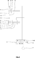
- Fig. 1 shows a pneumatic circuit diagram with a compressed air supply 1, in particular a pump or a reservoir, a pneumatic actuator 2 and a valve unit 3 for actuating the pneumatic control unit 2 by influencing the pneumatic Impingement.
- the valve unit 3 is here a 3/2-way valve 4 with a muscle power actuator 5, z. B. a push button.
- the 3/2-way valve 4 is shown in a venting position. With the muscle power actuator 5, the 3/2-way valve 4 can be brought against the action of a return spring 6 in a ventilation position in which the 3/2-way valve 4 connects the compressed air supply 1 with the pneumatic actuator 2.
- the pneumatic control unit 2 has a piston 7 with a piston rod 8, which is loaded with a return spring 9, here a compression spring, and a first chamber 10 and a second chamber 11 limited.
- the second chamber 11 is connected to a vent 12.
- the first chamber 10 can be aerated and vented via the 3/2-way valve 4.
- the first chamber 10 is vented and the piston in Fig. 1 moved to the left, so that the volume of the second chamber 11 is reduced. If the 3/2-way valve 4 or the valve unit 3 is brought back into the venting position by releasing the muscle power actuator 5 and the action of the return spring 6, the first chamber 10 is vented and the piston 7 moves due to the action of the return spring. 9 in Fig. 1 to the right, so that the volume of the second chamber 11 increases, while the volume of the first chamber 10 decreases.
- Fig. 2 shows another pneumatic circuit diagram. Across from Fig. 1 the circuit diagram has a second pneumatic control unit 2 '.
- the valve unit 3 is according to Fig. 2 a 5/2-way valve 13. This does not allow the switching between a ventilation position and a ventilation position, but between a first ventilation position with a first associated venting position and a second ventilation position with a second venting position connected thereto.
- Fig. 2 shows the 5/2-way valve 13 in the first ventilation position in which the first pneumatic actuator 2 is vented. The first piston 7 is thus acted upon to the left. The pneumatic actuator 2 ', however, is vented, so that the first vent position is present and the second piston 7' is thus acted upon by the action of the return spring 9 'to the right.
- Fig. 3 shows a vehicle seat release device 52 having a pneumatic actuator 2 with a Bowden cable 14 coupled thereto and a locking element 54.
- the Bowden cable 14 has a core 15 and a shell 16.
- the core 15 exits the sheath 16 at a first end sleeve 18 of the sheath 16, which is designed so that it can be mounted on a further component at least for supporting the sheath 16.
- the core 15 has a first coupling element 17, which here forms a circular cross-section and in particular is a ball.
- the coupling element 17 can directly form the locking element 54.
- the shell 16 is connected to the pneumatic control unit 2 in the region of a piston rod housing 19 or supported on this.
- the piston rod housing 19 is a part of a cylinder housing 20 of the pneumatic actuator 2 and slidably receives the piston rod 8, wherein the piston rod housing 19 is formed so long that the piston rod 8 is received during a whole working stroke of the piston 7 of the piston rod housing 19.
- the cylinder housing 20 also has a compressed air inlet 21.
- Fig. 4 shows the vehicle seat release device 52 in a longitudinal section.
- Fig. 5 shows an enlarged section Fig. 4 in the area of the cylinder housing.
- the Bowden cable 14 has a second end sleeve 22 of the sleeve 16, which is mounted in the piston rod housing 19.
- the core 15 extends from the second end sleeve 22 in the piston rod housing 19 and has at its end a second coupling element 23 which is also formed with a circular cross section, in particular as a ball.
- the coupling element 23 is accommodated in a receptacle 24 held on the piston rod 8.
- the receptacle 24 has a recess 25 for this purpose, through which the core 15 extends. If the recess 25 is open in cross-section, the core 15 can be inserted laterally into the receptacle 24.
- the receptacle 24 may have a fuse (not shown), which prevents the coupling element 23 again from the receptacle 24th also slipped.
- the core 15 may also have been threaded through the recess 25 before the coupling element 23 has been attached. In this case, no additional backup is necessary.
- the recording 24 forms here together with the coupling element 23 a ball joint 26.
- a tensile force acts at an angle to a longitudinal axis 27 of the piston rod 8 on the soul 15, this tensile force is transmitted by the ball joint 26 and the spherical coupling element 23 still ideal, so no load peaks on the receptacle 24, the coupling element 23 and the soul 15 occur.
- the piston rod 8 and provided with seals 28 against a wall of the cylinder housing 20 piston 7 have adjacent, cylindrical and stepped here recesses 29, 30, through which the return spring 9 extends through the piston 7 in the piston rod 8.
- the return spring 9 extends through a part of the piston rod 8 and is supported here on the receptacle 24.
- Fig. 4 shows the pneumatic actuator 2 in a vented state in which the second chamber 11 has its maximum volume and the first chamber 10 has its minimum volume.
- the pneumatic actuator 2 is thus in a first end position, in which the piston 7 rests against a first transverse wall 31 of the cylinder housing 20 and the return spring 9 has its maximum extent.
- the first end position may correspond to a first working position or a second working position of the piston 7.
- Fig. 6 and the enlarged section in Fig. 7 show the pneumatic actuator in a ventilated state in which the first chamber 10 its maximum volume and the second chamber 11 has its minimum volume.
- the pneumatic actuator 2 is thus in a second end position, in which the piston 7 rests against a second transverse wall 32 of the cylinder housing 20 and the return spring 9 has its minimum extension.
- the second end position may correspond to a second working position or a first working position of the piston 7.
- the return spring 9 is located in the second end position almost completely within the recesses 29, 30, so that the piston 7 can come to rest on the second transverse wall 32.
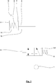
- Fig. 8 shows a vehicle seat 33 with a seat part 34 and a backrest 35.
- the backrest 35 is about a pivot axis 36 relative to the seat part 34 in pivoting directions 37th pivotable.
- the seat part 34 and the backrest 35 are connected to a connecting part 38 or a seat bracket, on which the pivot axis 36 is formed.
- the vehicle seat 33 has a locking device 39, by means of which a locking of a pivoting position of the backrest 35 is possible and which can be locked and released depending on the operation of the vehicle seat release device 52.
- the locking device 39 is designed here as a locking device 40.
- the locking device 39 has a locking wheel 41 as a locking element 42 and a locking pawl 43 as an engagement element 44.
- the locking element 42 is fixedly connected to the backrest 35, so that when the locking element 42 is rotated in a rotational direction 45, the backrest 35 is pivoted in a pivoting direction 37. However, the locking element 42 and thus the backrest 35 is prevented from rotating as long as the engagement element 44 engages in the locking element 42. This locking position is in Fig. 8 shown.
- the engagement member 44 can be released from engagement with the locking member 42 by operating a manual operation device 46, in which a hand lever 47 rotatably connected to the engagement member 44 is moved in a pivoting direction 48.
- a hand lever 47 rotatably connected to the engagement member 44 is moved in a pivoting direction 48.
- a return spring 49 here a compression spring 50
- a first support member 51 is applied, which is fixedly mounted on the connecting part 38. If the hand lever 47 is thus released, it is moved by the return spring 49 counter to the pivoting direction 48, so that he returns to its original position and the engagement member 44 is brought back into engagement with the locking member 42, so that the locking position is taken again.
- the engagement member 44 may be released from engagement with the lock member 42 by operating the vehicle seat release mechanism 52.
- the vehicle seat release device 52 With the vehicle seat release device 52 and the locking device 39, a vehicle seat lock 57 is formed.
- the vehicle seat release device 52 has the adjusting unit 2 and the Bowden cable 14, wherein the Bowden cable 14 is supported on its first end sleeve 18 of the shell 16 on a second support element 53.
- Fig. 9 and Fig. 10 show the vehicle seat lock 57 with the vehicle seat release device 52 in enlarged views.
- the control unit 2 has the compressed air connection 21, for reasons of clarity but other pneumatic components are not shown.
- the valve unit 3 can be pneumatically connected to the compressed air connection 21, so that the control unit 2 can be actuated via the valve unit 3.
- a pneumatic circuit as in Fig. 1 be formed represented.
- the vehicle seat release device 52 has the locking element 54.
- the locking element 54 is mechanically connected to the locking device 39 such that the locking device 39 is actuated when the locking element 54 is actuated.
- the locking element 54 is mechanically coupled to the engagement element 44.
- the locking element 54 and the engagement element 44 are not connected to each other over the entire degree of freedom of movement or stroke of the engagement member 44 driveably. Rather, these are connected by a game with each other.
- the locking element 54 and the engagement member 44 are coupled via a connecting pin 55 to the locking member 54 which engages in a slot 56 on the engagement member 44 and the hand lever 47 fixedly connected thereto. In this way, the operation of the hand lever 47 is disconnected from the operation of the locking member 54.
- the connecting pin 55 slides through the slot 56, which is dimensioned so that the connecting pin 55 can move freely in the slot 56 during the entire stroke of the hand lever 47.
- the actuation of the hand lever 47 is therefore possible without exercising forces on the locking element 54 and thus on the Bowden cable 14 and the adjusting unit 2 and without moving the locking element 54.
- the connecting bolt can engage a boundary of the elongated hole 56 and transmit the movement of the locking member 54 to the engagement member 44.
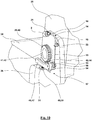
- Fig. 11 shows the vehicle seat 33 with the vehicle seat lock 57 and its locking device 39 and vehicle seat release device 52.
- the vehicle seat lock 57 has a second vehicle seat release device 52 'on.
- the second vehicle seat release device 52 ' is basically constructed in accordance with the first vehicle seat release device 52.
- the second vehicle seat release device 52 ' likewise has an adjusting unit 2' and a Bowden cable 14 '.
- the locking element 54 'of the second vehicle seat release device 52' and the locking element 54 of the first vehicle seat release device 52 are formed with a common coupling body, on which the respective coupling elements 17 of the vehicle seat release devices 52, 52 'are articulated.
- the common coupling body is a disc.
- Both vehicle seat release devices 52, 52 'thus engage the same coupling body. But their effects are exactly the opposite: as in the enlarged views of Fig. 12 . 13 and 14 can be seen, attack the souls 15, 15 'in opposite directions to the coupling body. That is, when the first Bowden cable 14 of the first vehicle seat release device 52 exerts a pulling force on the coupling body of the locking element 54, 54 ', as described above, the locking element 54, 54' is brought into the release position. However, if the second Bowden cable 14 'of the second vehicle seat release device 52' exerts a tensile force on the coupling body of the locking element 54, 54 ', the locking element 54, 54' is brought from the release position into the locking position. The second vehicle seat release device 52 'thus serves to facilitate the return to the locked position.
- the first end position of the piston 7 according to FIG Fig. 4 and 5 corresponds to the second operating position in which the locking element 54 is in its release position.
- the (in Fig. 11 to 14 not shown) second end position of the piston 7 according to Fig. 6 and 7 the first working position in which the locking element 54 is in its locked position.
- An actuation of the vehicle seat release devices 52, 52 ' for example, with a pneumatic circuit according to Fig. 2 be done so that by pressing (or releasing) the same muscle power actuator 5 both vehicle seat release devices 52, 52 'can be switched simultaneously from the locked position to the release position and vice versa.
Landscapes
- Engineering & Computer Science (AREA)
- Mechanical Engineering (AREA)
- Aviation & Aerospace Engineering (AREA)
- Transportation (AREA)
- General Engineering & Computer Science (AREA)
- Health & Medical Sciences (AREA)
- Oral & Maxillofacial Surgery (AREA)
- Seats For Vehicles (AREA)
Claims (15)
- Dispositif de détachement de siège de véhicule (52) avec un module de réglage (2) électrique ou pneumatique, un câble Bowden (14) et un élément de butée (54) qui sont raccordés les uns autres dans un couplage mécanique en série de telle sorte que, par un actionnement du module de réglage (2), l'élément de butée (54) peut être conduit d'une position de butée dans laquelle aucun déplacement du siège de véhicule (33) n'est possible vers une position de détachement dans laquelle un déplacement du siège de véhicule (33) est possible, et/ou de la position de détachement vers la position de butée.
- Dispositif de détachement de siège de véhicule (52) selon la revendication 1, caractérisé en ce que le module de réglage (2) est un module de réglage (2) pneumatique, et le module de réglage (2) pneumatique est actionnable par le biais d'une unité de soupape (3) actionnée manuellement.
- Dispositif de détachement de siège de véhicule (52) selon la revendication 1 ou 2, caractérisé en ce quea) le câble Bowden (14) présente une âme (15) et une gaine (16),b) l'élément de butée (54) est couplé mécaniquement à une première zone d'extrémité de l'âme (15),c) le module de réglage (2) présente un piston (7) sollicité pneumatiquement et un carter de cylindre (20), le piston (7) pouvant être conduit dans une première position de travail et dans une deuxième position de travail selon la sollicitation pneumatique dans le carter de cylindre (20),d) l'âme (15) du câble Bowden (14) est couplée mécaniquement au piston (7) dans une deuxième zone d'extrémité de telle sorte que, selon la sollicitation pneumatique du module de réglage (2) à la suite d'un mouvement du piston (7) à partir de la première position de travail vers la deuxième position de travail, l'élément de butée (54) peut être conduit dans la position de détachement.
- Dispositif de détachement de siège de véhicule (52) selon la revendication 3, caractérisé en ce quea) l'âme (15) du câble Bowden (14) présente un élément de couplage (23) dans la deuxième zone d'extrémité couplée au piston (7), etb) le piston (7) présente une tige de piston (8) qui dispose d'un logement (24) dans lequel l'élément de couplage (23) est logé de telle sorte que l'élément de couplage (23), au moins en présence de forces de traction agissant sur l'âme (15) dans la direction longitudinale de la tige de piston (8), est supporté sur le logement (24).
- Dispositif de détachement de siège de véhicule (52) selon la revendication 4, caractérisé en ce que le logement (24) forme un joint à rotule (26).
- Dispositif de détachement de siège de véhicule (52) selon l'une des revendications 3 à 5, caractérisé en ce que le module de réglage (2) pneumatique présente un ressort de rappel (6) avec lequel un rappel du piston (7) à partir de la deuxième position de travail vers le première position de travail est au moins assisté.
- Dispositif de détachement de siège de véhicule (52) selon la revendication 6, caractérisé en ce que le ressort de rappel (6) est disposé au moins partiellement dans un creux (29, 30) de la ou d'une tige de piston (8) et/ou du piston (7).
- Dispositif de détachement de siège de véhicule (52) selon l'une des revendications 2 à 7, caractérisé en ce que l'unité de soupape (3) est ou présente une vanne 3/2 voies (4) .
- Dispositif de détachement de siège de véhicule (52) selon l'une des revendications 2 à 8, caractérisé en ce que l'unité de soupape (3) et le module de réglage (2) pneumatique sont couplés pneumatiquement de telle sorte, et l'âme (15) du câble Bowden (14) et l'élément de butée (54) sont couplés pneumatiquement de telle sorte que, lors d'un actionnement de l'unité de soupape (3), l'élément de butée (54) est conduit dans la position de détachement et, lors d'une fin de l'actionnement de l'unité de soupape, l'élément de butée (54) est conduit dans la position de butée.
- Dispositif de butée de siège de véhicule (57) avec un système de butée (39) et un dispositif de détachement de siège de véhicule (52) selon l'une des revendications précédentes, le système de butée (39) étant couplé à l'élément de butée (54) du dispositif de détachement de siège de véhicule (52) et pouvant être détaché par le biais de cet élément, le système de butée (39) présentant un élément de verrouillage (42) raccordé fixement à une partie réglable du siège de véhicule (33) et un élément d'engrènement (44) engrenant dans l'élément de verrouillage (42) et l'élément de butée (54) du dispositif de détachement de siège de véhicule (52) étant couplé à l'élément d'engrènement (44).
- Dispositif de butée de siège de véhicule (57) selon la revendication 10, caractérisé en ce que, en plus du dispositif de détachement de siège de véhicule (52), il y a un dispositif d'actionnement manuel (46) avec lequel le système de butée (39) peut être actionné mécaniquement manuellement de telle sorte que le système de butée (39) peut au choix être actionnéa) par le biais du dispositif d'actionnement manuel (46) oub) par le biais du dispositif de détachement de siège de véhicule (52).
- Dispositif de butée de siège de véhicule (57) selon la revendication 11, caractérisé en ce que le dispositif d'actionnement manuel (46) présente un levier manuel (47) qui est couplé à l'élément d'engrènement (44).
- Dispositif de butée de siège de véhicule (57) selon l'une des revendications 10 à 12, caractérisé en ce que le système de butée (39) est découplé du dispositif de détachement de siège de véhicule (52) par le biais d'une course du dispositif d'actionnement manuel (46).
- Dispositif de butée de siège de véhicule (57), en particulier dispositif de butée de siège de véhicule (57) selon l'une des revendications 10 à 13, caractérisé en cea) qu'il y a un premier dispositif de détachement de siège de véhicule (52) selon l'une des revendications 1 à 9, avec lequel l'élément de butée (54, 54') peut être conduit dans la position de détachement, etb) en ce qu'il y un deuxième dispositif de détachement de siège de véhicule (52') selon l'une des revendications 1 à 9, avec lequel l'élément de butée (54, 54') peut être conduit dans la position de butée.
- Siège de véhicule (33) avec un dispositif de détachement de siège de véhicule (52) selon l'une des revendications 1 à 9 ou avec un dispositif de butée de siège de véhicule (57) selon l'une des revendications 10 à 14.
Priority Applications (1)
| Application Number | Priority Date | Filing Date | Title |
|---|---|---|---|
| EP16190697.9A EP3299213B1 (fr) | 2016-09-26 | 2016-09-26 | Dispositif de detachement de siege de vehicule, dispositif de butee de siege de vehicule et siege de vehicule |
Applications Claiming Priority (1)
| Application Number | Priority Date | Filing Date | Title |
|---|---|---|---|
| EP16190697.9A EP3299213B1 (fr) | 2016-09-26 | 2016-09-26 | Dispositif de detachement de siege de vehicule, dispositif de butee de siege de vehicule et siege de vehicule |
Publications (2)
| Publication Number | Publication Date |
|---|---|
| EP3299213A1 EP3299213A1 (fr) | 2018-03-28 |
| EP3299213B1 true EP3299213B1 (fr) | 2018-11-07 |
Family
ID=56997426
Family Applications (1)
| Application Number | Title | Priority Date | Filing Date |
|---|---|---|---|
| EP16190697.9A Active EP3299213B1 (fr) | 2016-09-26 | 2016-09-26 | Dispositif de detachement de siege de vehicule, dispositif de butee de siege de vehicule et siege de vehicule |
Country Status (1)
| Country | Link |
|---|---|
| EP (1) | EP3299213B1 (fr) |
Families Citing this family (1)
| Publication number | Priority date | Publication date | Assignee | Title |
|---|---|---|---|---|
| CN114435199B (zh) * | 2022-02-17 | 2023-05-05 | 延锋国际座椅系统有限公司 | 一种可快速逃生的电动折叠器以及汽车座椅 |
Family Cites Families (8)
| Publication number | Priority date | Publication date | Assignee | Title |
|---|---|---|---|---|
| DE3728297A1 (de) | 1987-08-25 | 1989-03-09 | Bergische Stahlindustrie | Bremse fuer schienenfahrzeuge |
| DE20218008U1 (de) | 2002-11-21 | 2003-03-06 | FESTO AG & Co., 73734 Esslingen | Anordnung von mehreren Handhabungsvorrichtungen |
| DE102004050773A1 (de) * | 2004-10-19 | 2006-04-20 | Daimlerchrysler Ag | Fahrzeugsitz für Kraftfahrzeuge |
| DE202006008821U1 (de) * | 2006-06-03 | 2006-08-31 | Bühler Motor GmbH | Stellantrieb, insbesondere für Sitzeinstelleinrichtungen |
| DE102010052273A1 (de) | 2010-11-23 | 2012-05-24 | Keiper Gmbh & Co. Kg | Entriegelungseinheit für einen Fahrzeugsitz |
| DE202014104868U1 (de) | 2014-10-13 | 2014-10-30 | Johnson Controls Technology Company | Verriegelungsmechanismus für einen Sitz und Sitz |
| DE202015103395U1 (de) | 2014-11-18 | 2015-07-09 | Johnson Controls Gmbh | Verriegelungsvorrichtung, insbesondere zur Verriegelung einer Lehne eines Fahrzeugsitzes mit einer Fahrzeugstruktur |
| DE102015100921B4 (de) * | 2015-01-22 | 2017-01-26 | Faurecia Autositze Gmbh | Bowdenzug-Verstellvorrichtung für einen Fahrzeugsitz und Fahrzeugsitz |
-
2016
- 2016-09-26 EP EP16190697.9A patent/EP3299213B1/fr active Active
Non-Patent Citations (1)
| Title |
|---|
| None * |
Also Published As
| Publication number | Publication date |
|---|---|
| EP3299213A1 (fr) | 2018-03-28 |
Similar Documents
| Publication | Publication Date | Title |
|---|---|---|
| DE2710585C2 (de) | Bremseinrichtung für Fahrzeuge, insbesondere für Schienenfahrzeuge, mit einem Federspeicher-Bremsgerät | |
| DE102013215028B4 (de) | Easy-Entry-System für einen Fahrzeugsitz und Fahrzeugsitz | |
| EP2713797B1 (fr) | Ensemble boucle | |
| DE102015012666A1 (de) | Baumaschine, insbesondere Gummiradwalze oder Straßenfertiger | |
| DE102005024468B4 (de) | Parksperre für Getriebe eines Kraftfahrzeuges | |
| DE102012012983B4 (de) | Fahrzeugsitz mit Rückenlehnenneigungseinstellung sowie Schulteranpassung | |
| DE202014100778U1 (de) | Betätigungsvorrichtung für eine Feststellbremse | |
| EP3299213A1 (fr) | Dispositif de detachement de siege de vehicule, dispositif de butee de siege de vehicule et siege de vehicule | |
| DE102014004863B4 (de) | Mechanische Höhenspeichervorrichtung für einen luftgefederten Fahrzeugsitz sowie luftgefederter Fahrzeugsitz mit einer solchen Vorrichtung | |
| DE102013021803A1 (de) | Aufstieg zur Fahrzeugtür eines Kraftfahrzeugs | |
| DE102018124575B4 (de) | Verfahrbarer Ladelift mit fernbedienter Schwenkarretierungseinheit für die Lenkrollen | |
| DE69116213T2 (de) | Not- und Feststelllbremsvorrichtung eines Fahrzeugs | |
| DE102012108157B3 (de) | Schienenfahrzeug mit einer Schiebetür und Schienenfahrzeugwagen mit einer WC-Einheit | |
| WO2006084445A2 (fr) | Porte comprenant un frein de porte | |
| DE202008012327U1 (de) | Betätigungseinrichtung zum Schalten eines Getriebes und zur Aktivierung einer Parkbremse | |
| DE102006007072B3 (de) | Vorrichtung zum mechanischen Lösen einer motorisch betätigten Feststellbremse für ein Kraftfahrzeug | |
| DE10356158B4 (de) | Bremseinrichtung eines Schienenfahrzeugs mit mehreren Federspeicherbremsen | |
| EP1319381B1 (fr) | Chaise mobile à roulettes pour le transport des malades | |
| DE20213535U1 (de) | Bremseinrichtung für Fahrzeuganhänger mit Nachstelleinrichtung | |
| DE102006019768B4 (de) | Beinauflagevorrichtung in einem Kraftfahrzeug | |
| DE202004006526U1 (de) | Betätigungsvorrichtung für eine Notentriegelungseinrichtung an Türen für Fahrzeuge des öffentlichen Personen-Nah- und -Fernverkehrs | |
| DE202005006992U1 (de) | Verriegelungsvorrichtung für einen Fahrzeugsitz | |
| DE102005009040A1 (de) | Zusätzliche Sitzlängsverstellung | |
| DE102012216156B4 (de) | Verriegelungsvorrichtung für Lastentransportfahrzeuge | |
| DE4100628A1 (de) | Handbremsbetaetigungsvorrichtung |
Legal Events
| Date | Code | Title | Description |
|---|---|---|---|
| PUAI | Public reference made under article 153(3) epc to a published international application that has entered the european phase |
Free format text: ORIGINAL CODE: 0009012 |
|
| STAA | Information on the status of an ep patent application or granted ep patent |
Free format text: STATUS: REQUEST FOR EXAMINATION WAS MADE |
|
| 17P | Request for examination filed |
Effective date: 20170323 |
|
| AK | Designated contracting states |
Kind code of ref document: A1 Designated state(s): AL AT BE BG CH CY CZ DE DK EE ES FI FR GB GR HR HU IE IS IT LI LT LU LV MC MK MT NL NO PL PT RO RS SE SI SK SM TR |
|
| AX | Request for extension of the european patent |
Extension state: BA ME |
|
| GRAP | Despatch of communication of intention to grant a patent |
Free format text: ORIGINAL CODE: EPIDOSNIGR1 |
|
| STAA | Information on the status of an ep patent application or granted ep patent |
Free format text: STATUS: GRANT OF PATENT IS INTENDED |
|
| INTG | Intention to grant announced |
Effective date: 20180525 |
|
| GRAS | Grant fee paid |
Free format text: ORIGINAL CODE: EPIDOSNIGR3 |
|
| GRAA | (expected) grant |
Free format text: ORIGINAL CODE: 0009210 |
|
| STAA | Information on the status of an ep patent application or granted ep patent |
Free format text: STATUS: THE PATENT HAS BEEN GRANTED |
|
| RBV | Designated contracting states (corrected) |
Designated state(s): AL AT BE BG CH CY CZ DE DK EE ES FI FR GB GR HR HU IE IS IT LI LT LU LV MC MK MT NL NO PL PT RO RS SE SI SK SM TR |
|
| AK | Designated contracting states |
Kind code of ref document: B1 Designated state(s): AL AT BE BG CH CY CZ DE DK EE ES FI FR GB GR HR HU IE IS IT LI LT LU LV MC MK MT NL NO PL PT RO RS SE SI SK SM TR |
|
| REG | Reference to a national code |
Ref country code: GB Ref legal event code: FG4D Free format text: NOT ENGLISH |
|
| REG | Reference to a national code |
Ref country code: CH Ref legal event code: EP Ref country code: AT Ref legal event code: REF Ref document number: 1061652 Country of ref document: AT Kind code of ref document: T Effective date: 20181115 |
|
| REG | Reference to a national code |
Ref country code: DE Ref legal event code: R096 Ref document number: 502016002424 Country of ref document: DE |
|
| REG | Reference to a national code |
Ref country code: IE Ref legal event code: FG4D Free format text: LANGUAGE OF EP DOCUMENT: GERMAN |
|
| REG | Reference to a national code |
Ref country code: NL Ref legal event code: MP Effective date: 20181107 |
|
| REG | Reference to a national code |
Ref country code: LT Ref legal event code: MG4D |
|
| PG25 | Lapsed in a contracting state [announced via postgrant information from national office to epo] |
Ref country code: ES Free format text: LAPSE BECAUSE OF FAILURE TO SUBMIT A TRANSLATION OF THE DESCRIPTION OR TO PAY THE FEE WITHIN THE PRESCRIBED TIME-LIMIT Effective date: 20181107 Ref country code: LV Free format text: LAPSE BECAUSE OF FAILURE TO SUBMIT A TRANSLATION OF THE DESCRIPTION OR TO PAY THE FEE WITHIN THE PRESCRIBED TIME-LIMIT Effective date: 20181107 Ref country code: HR Free format text: LAPSE BECAUSE OF FAILURE TO SUBMIT A TRANSLATION OF THE DESCRIPTION OR TO PAY THE FEE WITHIN THE PRESCRIBED TIME-LIMIT Effective date: 20181107 Ref country code: LT Free format text: LAPSE BECAUSE OF FAILURE TO SUBMIT A TRANSLATION OF THE DESCRIPTION OR TO PAY THE FEE WITHIN THE PRESCRIBED TIME-LIMIT Effective date: 20181107 Ref country code: BG Free format text: LAPSE BECAUSE OF FAILURE TO SUBMIT A TRANSLATION OF THE DESCRIPTION OR TO PAY THE FEE WITHIN THE PRESCRIBED TIME-LIMIT Effective date: 20190207 Ref country code: FI Free format text: LAPSE BECAUSE OF FAILURE TO SUBMIT A TRANSLATION OF THE DESCRIPTION OR TO PAY THE FEE WITHIN THE PRESCRIBED TIME-LIMIT Effective date: 20181107 Ref country code: NO Free format text: LAPSE BECAUSE OF FAILURE TO SUBMIT A TRANSLATION OF THE DESCRIPTION OR TO PAY THE FEE WITHIN THE PRESCRIBED TIME-LIMIT Effective date: 20190207 Ref country code: IS Free format text: LAPSE BECAUSE OF FAILURE TO SUBMIT A TRANSLATION OF THE DESCRIPTION OR TO PAY THE FEE WITHIN THE PRESCRIBED TIME-LIMIT Effective date: 20190307 |
|
| PG25 | Lapsed in a contracting state [announced via postgrant information from national office to epo] |
Ref country code: RS Free format text: LAPSE BECAUSE OF FAILURE TO SUBMIT A TRANSLATION OF THE DESCRIPTION OR TO PAY THE FEE WITHIN THE PRESCRIBED TIME-LIMIT Effective date: 20181107 Ref country code: GR Free format text: LAPSE BECAUSE OF FAILURE TO SUBMIT A TRANSLATION OF THE DESCRIPTION OR TO PAY THE FEE WITHIN THE PRESCRIBED TIME-LIMIT Effective date: 20190208 Ref country code: NL Free format text: LAPSE BECAUSE OF FAILURE TO SUBMIT A TRANSLATION OF THE DESCRIPTION OR TO PAY THE FEE WITHIN THE PRESCRIBED TIME-LIMIT Effective date: 20181107 Ref country code: SE Free format text: LAPSE BECAUSE OF FAILURE TO SUBMIT A TRANSLATION OF THE DESCRIPTION OR TO PAY THE FEE WITHIN THE PRESCRIBED TIME-LIMIT Effective date: 20181107 Ref country code: AL Free format text: LAPSE BECAUSE OF FAILURE TO SUBMIT A TRANSLATION OF THE DESCRIPTION OR TO PAY THE FEE WITHIN THE PRESCRIBED TIME-LIMIT Effective date: 20181107 Ref country code: PT Free format text: LAPSE BECAUSE OF FAILURE TO SUBMIT A TRANSLATION OF THE DESCRIPTION OR TO PAY THE FEE WITHIN THE PRESCRIBED TIME-LIMIT Effective date: 20190307 |
|
| PG25 | Lapsed in a contracting state [announced via postgrant information from national office to epo] |
Ref country code: DK Free format text: LAPSE BECAUSE OF FAILURE TO SUBMIT A TRANSLATION OF THE DESCRIPTION OR TO PAY THE FEE WITHIN THE PRESCRIBED TIME-LIMIT Effective date: 20181107 Ref country code: IT Free format text: LAPSE BECAUSE OF FAILURE TO SUBMIT A TRANSLATION OF THE DESCRIPTION OR TO PAY THE FEE WITHIN THE PRESCRIBED TIME-LIMIT Effective date: 20181107 Ref country code: CZ Free format text: LAPSE BECAUSE OF FAILURE TO SUBMIT A TRANSLATION OF THE DESCRIPTION OR TO PAY THE FEE WITHIN THE PRESCRIBED TIME-LIMIT Effective date: 20181107 Ref country code: PL Free format text: LAPSE BECAUSE OF FAILURE TO SUBMIT A TRANSLATION OF THE DESCRIPTION OR TO PAY THE FEE WITHIN THE PRESCRIBED TIME-LIMIT Effective date: 20181107 |
|
| REG | Reference to a national code |
Ref country code: DE Ref legal event code: R097 Ref document number: 502016002424 Country of ref document: DE |
|
| PG25 | Lapsed in a contracting state [announced via postgrant information from national office to epo] |
Ref country code: RO Free format text: LAPSE BECAUSE OF FAILURE TO SUBMIT A TRANSLATION OF THE DESCRIPTION OR TO PAY THE FEE WITHIN THE PRESCRIBED TIME-LIMIT Effective date: 20181107 Ref country code: SK Free format text: LAPSE BECAUSE OF FAILURE TO SUBMIT A TRANSLATION OF THE DESCRIPTION OR TO PAY THE FEE WITHIN THE PRESCRIBED TIME-LIMIT Effective date: 20181107 Ref country code: EE Free format text: LAPSE BECAUSE OF FAILURE TO SUBMIT A TRANSLATION OF THE DESCRIPTION OR TO PAY THE FEE WITHIN THE PRESCRIBED TIME-LIMIT Effective date: 20181107 Ref country code: SM Free format text: LAPSE BECAUSE OF FAILURE TO SUBMIT A TRANSLATION OF THE DESCRIPTION OR TO PAY THE FEE WITHIN THE PRESCRIBED TIME-LIMIT Effective date: 20181107 |
|
| PLBE | No opposition filed within time limit |
Free format text: ORIGINAL CODE: 0009261 |
|
| STAA | Information on the status of an ep patent application or granted ep patent |
Free format text: STATUS: NO OPPOSITION FILED WITHIN TIME LIMIT |
|
| 26N | No opposition filed |
Effective date: 20190808 |
|
| PG25 | Lapsed in a contracting state [announced via postgrant information from national office to epo] |
Ref country code: TR Free format text: LAPSE BECAUSE OF FAILURE TO SUBMIT A TRANSLATION OF THE DESCRIPTION OR TO PAY THE FEE WITHIN THE PRESCRIBED TIME-LIMIT Effective date: 20181107 |
|
| PG25 | Lapsed in a contracting state [announced via postgrant information from national office to epo] |
Ref country code: MC Free format text: LAPSE BECAUSE OF FAILURE TO SUBMIT A TRANSLATION OF THE DESCRIPTION OR TO PAY THE FEE WITHIN THE PRESCRIBED TIME-LIMIT Effective date: 20181107 |
|
| REG | Reference to a national code |
Ref country code: CH Ref legal event code: PL |
|
| PG25 | Lapsed in a contracting state [announced via postgrant information from national office to epo] |
Ref country code: LI Free format text: LAPSE BECAUSE OF NON-PAYMENT OF DUE FEES Effective date: 20190930 Ref country code: LU Free format text: LAPSE BECAUSE OF NON-PAYMENT OF DUE FEES Effective date: 20190926 Ref country code: IE Free format text: LAPSE BECAUSE OF NON-PAYMENT OF DUE FEES Effective date: 20190926 Ref country code: CH Free format text: LAPSE BECAUSE OF NON-PAYMENT OF DUE FEES Effective date: 20190930 |
|
| REG | Reference to a national code |
Ref country code: BE Ref legal event code: MM Effective date: 20190930 |
|
| PG25 | Lapsed in a contracting state [announced via postgrant information from national office to epo] |
Ref country code: BE Free format text: LAPSE BECAUSE OF NON-PAYMENT OF DUE FEES Effective date: 20190930 |
|
| PG25 | Lapsed in a contracting state [announced via postgrant information from national office to epo] |
Ref country code: FR Free format text: LAPSE BECAUSE OF NON-PAYMENT OF DUE FEES Effective date: 20190930 |
|
| GBPC | Gb: european patent ceased through non-payment of renewal fee |
Effective date: 20200926 |
|
| PG25 | Lapsed in a contracting state [announced via postgrant information from national office to epo] |
Ref country code: CY Free format text: LAPSE BECAUSE OF FAILURE TO SUBMIT A TRANSLATION OF THE DESCRIPTION OR TO PAY THE FEE WITHIN THE PRESCRIBED TIME-LIMIT Effective date: 20181107 |
|
| PG25 | Lapsed in a contracting state [announced via postgrant information from national office to epo] |
Ref country code: MT Free format text: LAPSE BECAUSE OF FAILURE TO SUBMIT A TRANSLATION OF THE DESCRIPTION OR TO PAY THE FEE WITHIN THE PRESCRIBED TIME-LIMIT Effective date: 20181107 Ref country code: HU Free format text: LAPSE BECAUSE OF FAILURE TO SUBMIT A TRANSLATION OF THE DESCRIPTION OR TO PAY THE FEE WITHIN THE PRESCRIBED TIME-LIMIT; INVALID AB INITIO Effective date: 20160926 |
|
| PG25 | Lapsed in a contracting state [announced via postgrant information from national office to epo] |
Ref country code: GB Free format text: LAPSE BECAUSE OF NON-PAYMENT OF DUE FEES Effective date: 20200926 |
|
| PG25 | Lapsed in a contracting state [announced via postgrant information from national office to epo] |
Ref country code: SI Free format text: LAPSE BECAUSE OF FAILURE TO SUBMIT A TRANSLATION OF THE DESCRIPTION OR TO PAY THE FEE WITHIN THE PRESCRIBED TIME-LIMIT Effective date: 20181107 |
|
| PG25 | Lapsed in a contracting state [announced via postgrant information from national office to epo] |
Ref country code: MK Free format text: LAPSE BECAUSE OF FAILURE TO SUBMIT A TRANSLATION OF THE DESCRIPTION OR TO PAY THE FEE WITHIN THE PRESCRIBED TIME-LIMIT Effective date: 20181107 |
|
| REG | Reference to a national code |
Ref country code: AT Ref legal event code: MM01 Ref document number: 1061652 Country of ref document: AT Kind code of ref document: T Effective date: 20210926 |
|
| PG25 | Lapsed in a contracting state [announced via postgrant information from national office to epo] |
Ref country code: AT Free format text: LAPSE BECAUSE OF NON-PAYMENT OF DUE FEES Effective date: 20210926 |
|
| P01 | Opt-out of the competence of the unified patent court (upc) registered |
Effective date: 20230529 |
|
| PGFP | Annual fee paid to national office [announced via postgrant information from national office to epo] |
Ref country code: DE Payment date: 20250710 Year of fee payment: 10 |