EP3299328A1 - Regleranordnung und aufzug - Google Patents
Regleranordnung und aufzug Download PDFInfo
- Publication number
- EP3299328A1 EP3299328A1 EP17184215.6A EP17184215A EP3299328A1 EP 3299328 A1 EP3299328 A1 EP 3299328A1 EP 17184215 A EP17184215 A EP 17184215A EP 3299328 A1 EP3299328 A1 EP 3299328A1
- Authority
- EP
- European Patent Office
- Prior art keywords
- axle
- support
- governor assembly
- main pulley
- guide rail
- Prior art date
- Legal status (The legal status is an assumption and is not a legal conclusion. Google has not performed a legal analysis and makes no representation as to the accuracy of the status listed.)
- Granted
Links
Images


Classifications
-
- B—PERFORMING OPERATIONS; TRANSPORTING
- B66—HOISTING; LIFTING; HAULING
- B66B—ELEVATORS; ESCALATORS OR MOVING WALKWAYS
- B66B5/00—Applications of checking, fault-correcting, or safety devices in elevators
- B66B5/02—Applications of checking, fault-correcting, or safety devices in elevators responsive to abnormal operating conditions
- B66B5/04—Applications of checking, fault-correcting, or safety devices in elevators responsive to abnormal operating conditions for detecting excessive speed
- B66B5/044—Mechanical overspeed governors
-
- B—PERFORMING OPERATIONS; TRANSPORTING
- B66—HOISTING; LIFTING; HAULING
- B66B—ELEVATORS; ESCALATORS OR MOVING WALKWAYS
- B66B1/00—Control systems of elevators in general
- B66B1/24—Control systems with regulation, i.e. with retroactive action, for influencing travelling speed, acceleration, or deceleration
- B66B1/28—Control systems with regulation, i.e. with retroactive action, for influencing travelling speed, acceleration, or deceleration electrical
- B66B1/32—Control systems with regulation, i.e. with retroactive action, for influencing travelling speed, acceleration, or deceleration electrical effective on braking devices, e.g. acting on electrically controlled brakes
-
- B—PERFORMING OPERATIONS; TRANSPORTING
- B66—HOISTING; LIFTING; HAULING
- B66B—ELEVATORS; ESCALATORS OR MOVING WALKWAYS
- B66B5/00—Applications of checking, fault-correcting, or safety devices in elevators
- B66B5/02—Applications of checking, fault-correcting, or safety devices in elevators responsive to abnormal operating conditions
- B66B5/16—Braking or catch devices operating between cars, cages, or skips and fixed guide elements or surfaces in hoistway or well
- B66B5/18—Braking or catch devices operating between cars, cages, or skips and fixed guide elements or surfaces in hoistway or well and applying frictional retarding forces
Definitions
- the present invention relates to the technical field of an elevator governor, and in particular, to a follower-type governor especially suitable for being arranged in a narrow shaft and an elevator having such a governor.
- a governor for an elevator is known. When a speed of the elevator exceeds a particular range, the governor starts a switch to power off an elevator motor, so that the elevator slows down or brakes. In a special situation in which the elevator continues to speed up, the governor starts a mechanical retarding mechanism, which is usually a safety gear frictionally engaged with a guide rail, so as to slow down the elevator through friction between the safety gear and the guide rail.
- governors are mounted at the top of the shaft or in a top machine room. Such governors may be used at a car side or a counterweight side of the elevator. However, in some special buildings, such governors are not allowed to be mounted due to limitations of site conditions, for example, the top of the elevator shaft has no space for disposing the governor.
- the prior art provides a follower-type governor moving along with the car.
- An objective of the present invention is to solve or at least alleviate problems in the prior art.
- the present invention provides a governor assembly and an elevator, wherein the governor assembly includes:
- Particular embodiments may include any of the following optional features, alone or in combination:
- the core ring may be fixedly connected to the first axle by using a key.
- the first axle may be disposed to be substantially perpendicular to a guide rail plane defined by a guide rail.
- the support may comprise a first support and a second support disposed opposite to each other at two sides of the guide rail.
- the first support and/or the second support may be selected from a tablet support, a tripod, a rod support, a railing support, or a net support.
- the first axle may comprise a middle portion located between the first support and the second support, and an end portion extending from the first support; and the first safety device may be connected to the middle portion of the first axle and the main pulley is rotatably supported on the end portion of the first axle.
- the governor assembly further may comprise a second safety device, the second safety device may be actuated by the rotation of a second axle, and the second axle may move jointly with the first axle by using a connecting rod mechanism.
- the connecting rod mechanism may comprise a first arm, a connecting rod, and a second arm.
- the second axle may be rotatably supported by the first support and the second support; the second axle may comprise a middle portion located between the first support and the second support, and an end portion extending from the first support; and the connecting rod mechanism may be connected between the end portions of the first axle and the second axle.
- the first guide pulley may be located at one side of the main pulley and may be higher than the main pulley.
- the main pulley may be disposed near a first guide rail; and the governor assembly further may comprise a second guide pulley which is disposed near a second guide rail.
- the governor assembly further may comprise a housing at least partially covering the main pulley and the first guide pulley.
- the first safety device may comprise: at least one swing arm, of which a fist end is fixedly connected to the first axle and a second end is located near the first guide rail; a pull rod suspending from the second end of the at least one swing arm; and an engaging member at the bottom of the pull rod; wherein the pull rod may be driven by the rotation of the swing arm to pull the engaging member, and then the engaging member may be frictionally engaged with the first guide rail.
- the first safety device may comprise two swing arms, pull rods connected to the two swing arms suspend from two sides of the first guide rail, and engaging members at the bottoms of the two swing arms are frictionally engaged with the guide rail at the two sides of the guide rail.
- An elevator may be configured with the governor assembly as described above.
- the governor assembly may be disposed at a car side.
- the governor assembly may be disposed at a counterweight side.
- the present invention provides a governor assembly and an elevator, wherein the governor assembly includes:
- Particular embodiments may include any of the following optional features, alone or in combination:
- the governor assembly further may comprise: a second axle, which is rotatably supported by the first support and the second support, and comprises a middle portion located between the first support and the second support, and an end portion extending from the first support; a connecting rod mechanism, connecting the end portions of the first axle and the second axle, so that the first axle and the second axle move jointly; and a second safety device which is connected to the middle portion of the second axle and actuated by the rotation of the second axle.
- the governor assembly further may comprise a second guide pulley, wherein the second guide pulley is disposed near the guide rail.
- governor assembly according to the second aspect may comprise any of the features described above with respect to the governor assembly according to the first aspect.
- An elevator may be configured with the governor assembly as described above.
- the governor assembly may be disposed at a car side.
- the governor assembly may be disposed at a counterweight side.
- a governor assembly according to an embodiment of the present invention and its application at a counterweight side of an elevator are described in detail below with reference to FIG. 1 to FIG. 4 . It should be understood that, although the present invention uses an example in which the governor assembly is used at the counterweight side, the governor assembly according to the present invention may also be used at a car side of the elevator.
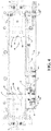
- FIG. 1 illustrates a schematic diagram of a single governor assembly 200 according to an embodiment of the present invention.
- the governor assembly 200 includes a main pulley 231 rotatably supported by a first axle 21, a first guide pulley 24, and a second guide pulley 25.
- FIG. 1 further illustrates an upper actuation part of a first safety device 50 related to the first axle 21 and an upper actuation part of a second safety device 60 moved jointly with the first safety device 50 by using a connecting rod system 70.
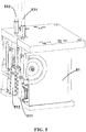
- FIG. 2 illustrates an application of the governor assembly 200 in FIG. 1 at the counterweight side.
- the governor assembly 200 may also be mounted at the bottom or in the middle of the counterweight rack 30 in an alternative embodiment.
- the counterweight side is also referred to as a balanced side, wherein a counterweight block is configured so as to keep balance with the car.
- a shaft at the counterweight side is designed to be relatively narrow; the top, the bottom, and the surrounding space of the counterweight side are all rather narrow. Therefore, to configure a follower-type governor at the counterweight side, challenges from the space and power supply need to be overcome.
- the counterweight side generally includes: a first guide rail 31 and a second guide rail 32 that are located in a same plane and define a guide rail plane; the counterweight rack 30 moving along the first guide rail 31 and the second guide rail 32 by using multiple guide boots, for example, guide boots 91 and 92 shown in FIG. 2 ; and multiple counterweight blocks 90 disposed in the counterweight rack 30.
- FIG. 2 illustrates the governor assembly 200, which is mounted on a support at the top of the counterweight rack 30.
- the support is a pair of opposite supports at the top of the counterweight rack 30, including a first support 33 and a second support 34.
- the first support 33 and the second support 34 substantially extend in a direction parallel to the guide rail plane where the first guide rail 31 and the second guide rail 32 are located, and the first support 33 and the second support 34 are substantially flush with a long side of the counterweight rack or the counterweight block.
- the first support 33 and the second support 34 are each in the form of a tablet, but in an alternative embodiment, the support is not limited to the form of a tablet, for example, the support may be a tripod, a rod support, a railing support, or a net support mounted at the top or the bottom of the counterweight rack 30. It should be understood that, persons skilled in the art may design various kinds of supports, provided that the support can support the multiple components.
- the governor assembly 200 further includes a housing 35, wherein the housing 35 is illustrated to be transparent so that internal components of the governor assembly 200 are visible.
- the housing 35 at least partially covers main components of the governor assembly 200, such as the main pulley and/or one or more guide pulleys.
- the governor assembly 200 includes a first axle 21, wherein the first axle 21 is supported by a support.
- the support is disposed to be a pair of opposite supports, including a first support 33 and a second support 34.
- the first support 33 and the second support 34 are substantially parallel to each other, are located opposite to each other at two sides of the first and second guide rails 31 and 32 or the guide rail plane, and both substantially extend in a direction parallel to the guide rail plane where the first guide rail 31 and the second guide rail 32 are located.
- the first axle 21 passes through holes in corresponding positions on the first support 33 and the second support 34 to be rotatably supported on the first support 33 and the second support 34, for example, the first axle is disposed at a side near the first guide rail 31.
- the first axle 21 has a middle portion located between the first support 33 and the second support 34, and at least one end portion extending to outer sides of the first support 33 and the second support 34.
- the end portion extends from the first support 33 to the outer side of the first support 33.
- the main pulley 231 is rotatably supported on the end portion of the first axle 21, for example, by using a bearing 234.
- the first guide pulley 24 is disposed near the main pulley 231, specifically, at a position on the right side of the main pulley 231 and slightly higher than the main pulley 231.
- the first guide pulley 24 (and the optional second guide pulley 25) and the main pulley 231 are substantially in the same plane; the plane in which the first guide pulley 24 (and the optional second guide pulley 25) and the main pulley 231 are located is parallel to the guide rail plane.
- the first guide pulley 24 is rotatably supported on a first guide pulley axle 241, for example, the first guide pulley 24 is supported on the first guide pulley axle 241 by using a bearing 242.
- the first guide pulley axle 241 is mounted only on the first support 33, and extends outwardly from the first support 33.
- the second guide pulley 25 is disposed near the second guide rail 32 on the other side of the shaft, and may be located at the same side of the main pulley 231 with the first guide pulley 24.
- the second guide pulley 25 may be rotatably supported by a second guide pulley axle 251 mounted on the first support 33, for example, the second guide pulley is supported by using a bearing 252.
- the second guide pulley axle 251 extends outwardly only from the first support 33.
- the second guide pulley 25 is used to guide a rope R to suspend near the second guide rail 32, so that the main pulley 231 and the first guide pulley 24 can be arranged in more optional positions.
- the third guide pulley 25 may be omitted.
- the main pulley 231, the first guide pulley 24, and the second guide pulley 25 are each provided with a rope groove on the periphery.
- the rope R is rolled over the main pulley 231, the first guide pulley 24, and the second guide pulley 25 successively along the rope grooves. It is known that, an upper end of the rope R is connected to the top of the shaft, and a lower end of the rope R is connected to the bottom of the shaft or is provided with a heavy object to tighten the rope R.
- the second guide pulley 25 guides the rope R to suspend near the second guide rail 32.
- the rope R drives, due to friction, the main pulley 231, the first guide pulley 24, and the second guide pulley 25 to rotate about respective support axles, wherein the rotation speeds of the main pulley 231 and the guide pulleys are directly associated with the moving speed of the counterweight rack, and therefore are associated with a moving speed of the car.
- a centrifugal tripping mechanism 26 is provided on the first axle 21, and between the main pulley 231 and the first axle 21, so that when a rotating speed of the main pulley 231 exceeds a preset value, the centrifugal tripping mechanism 26 enables the main pulley 231 and the first axle 21 to trip each other and rotate together. That is, when the counterweight rack, for example, is out of control and moves too fast, the main pulley 231 speeds up, and the centrifugal tripping mechanism 26 enables, due to its ever-increasing centrifugal force, the main pulley 231 and the first axle 21 to trip each other and rotate together. At this time, the main pulley 231 drives the first axle 21 to rotate together, so as to actuate a first safety device 50 related to the first axle 21 and further actuate a second safety device 60 optionally by using a connecting rod mechanism 70.
- the first safety device 50 includes one or two swing arms, such as a first swing arm 541 and a second swing arm 542, which are located between the first support 33 and the second support 34 and fixedly connected to the first axle 21.
- First ends of the first swing arm 541 and the second swing arm 542 are fixedly connected to the first axle 21, and second ends of the first swing arm 541 and the second swing arm 542 are connected to corresponding pull rods 531 and 532 respectively.
- the corresponding pull rods 531 and 532 suspend from two sides of the guide rail 31, and are provided with an engaging device 51 (shown in FIG. 5 ) at the bottoms thereof.
- the bottoms of the pull rods 531 and 532 are connected to engaging members 511 and 512 respectively, whereas the engaging members 511 and 512 are, for example, in the form of a wedge, and are located at a front side and a rear side of the first guide rail 31 (the first guide rail 31 is not drawn in FIG. 5 ) respectively.
- the first safety device 50 is actuated as the first axle 21 rotates; the first swing arm 541 and the second swing arm 542 rotate with the first axle 21 to pull the first pull rod 531 and the second pull rod 532, so that the engaging members 511 and 512 rub against the guide rail 31 to brake the counterweight rack 30.
- a safety device of another type may be selected, provided that the safety device can be actuated by the rotation of an axle.
- the governor assembly 200 further includes a second safety device 60, which includes a second axle 22. Similar to the first axle 21, the second axle 22 can also be rotatably supported by both the first support 33 and the second support 33.
- the second axle 22 includes a middle portion located between the first support 33 and the second support 34, and an end portion extending to an outer side of the first support 33.
- the end portions of the second axle 22 and the first axle 21 are coupled by using the connecting rod mechanism 70, so that by means of the connecting rod mechanism 70, the second axle 22 is driven to rotate by the rotation of the first axle 21.
- the connecting rod mechanism 70 may include a first arm 71, a connecting rod 72, and a second arm 73.
- the second safety device 60 includes one or two swing arms, such as a third swing arm 641 and a fourth swing arm 642, which are fixedly connected to the middle portions of the the first support 33 and the second support 34 of the second axle 22.
- First ends of the third swing arm 641 and the fourth swing arm 642 are fixedly connected to the second axle 22, and second ends of the third swing arm 641 and the fourth swing arm 642 are connected to corresponding third and fourth pull rods 631 and 632 respectively.
- the corresponding pull rods 631 and 632 suspend from two sides of the second guide rail 32, and are each provided with an engaging member at the bottom.
- the engaging members are, for example, in the form of a wedge, and are located at a front side and a rear side of the second guide rail 32 respectively.
- the second axle 22 is driven to rotate to actuate the second safety device 60; the third swing arm 641 and the fourth swing arm 642 rotate with the second axle 22 to pull the corresponding third and fourth pull rods 631 and 632, so that the engaging members rub against the second guide rail 32 to brake the counterweight rack 30.
- the centrifugal tripping mechanism 26 in an embodiment is described in detail below with reference to FIG. 6 .
- the centrifugal tripping mechanism 26 is disposed on a back side of the main pulley 231, that is, between the main pulley 231 and the first support 33.
- the centrifugal tripping mechanism 26 includes a core ring 262 which is fixedly connected to the first axle 21, for example, by using a key (not shown).
- the centrifugal tripping mechanism 26 further includes a centrifugal tripping member 261, wherein the centrifugal tripping member 261 rotates with the main pulley 231, enables the main pulley 231 and the core ring 262 to trip each other when a rotating speed of the main pulley 231 exceeds a preset value, and enables the main pulley 231, the core ring 262, and the first axle 21 coupled to the core ring 262 to rotate together.
- the centrifugal tripping member is known in the art. In some embodiments, the centrifugal tripping member 261 may use a type recorded in US patent No.
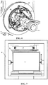
- FIG. 7 illustrates a sectional view of a shaft.
- the shaft is defined by a boundary 4, and is partitioned into a car side and a counterweight side by a partition plate 3.
- the shaft at the car side is larger so as to accommodate multiple types of governors.
- the counterweight side in which a counterweight block 2 is disposed has a small space, and especially, a distance from the counterweight block 2 to the partition plate 3 is generally less than 150 mm. As shown in FIG.
- the governor assembly 200 in the embodiment of the present invention may be compactly integrated with the counterweight side of the elevator, and merely the thickness and height of the top of the counterweight rack at the counterweight side are slightly increased, for example, the thickness is increased by about 100 mm and the height is increased by about 90 mm.
- a follower-type governor can be mounted at the counterweight side or the car side due to such a compact design.
Landscapes
- Engineering & Computer Science (AREA)
- Mechanical Engineering (AREA)
- Automation & Control Theory (AREA)
- Maintenance And Inspection Apparatuses For Elevators (AREA)
Applications Claiming Priority (1)
| Application Number | Priority Date | Filing Date | Title |
|---|---|---|---|
| CN201610620731.5A CN107673155B (zh) | 2016-08-02 | 2016-08-02 | 限速器组件以及电梯 |
Publications (2)
| Publication Number | Publication Date |
|---|---|
| EP3299328A1 true EP3299328A1 (de) | 2018-03-28 |
| EP3299328B1 EP3299328B1 (de) | 2020-03-25 |
Family
ID=59506154
Family Applications (1)
| Application Number | Title | Priority Date | Filing Date |
|---|---|---|---|
| EP17184215.6A Active EP3299328B1 (de) | 2016-08-02 | 2017-08-01 | Geschwindigkeitsbegrenzeranordnung und aufzug |
Country Status (3)
| Country | Link |
|---|---|
| US (1) | US10745245B2 (de) |
| EP (1) | EP3299328B1 (de) |
| CN (1) | CN107673155B (de) |
Families Citing this family (3)
| Publication number | Priority date | Publication date | Assignee | Title |
|---|---|---|---|---|
| CN108275534A (zh) * | 2018-03-28 | 2018-07-13 | 苏州尼隆电梯部件有限公司 | 一种电梯限速器 |
| CN111115406B (zh) * | 2020-01-17 | 2024-09-17 | 苏州普乐太自控技术有限公司 | 一种具有防溜车功能的电梯 |
| US12116242B2 (en) | 2022-10-25 | 2024-10-15 | Tk Elevator Innovation And Operations Gmbh | Elevator counterweight mounted governor assemblies |
Citations (7)
| Publication number | Priority date | Publication date | Assignee | Title |
|---|---|---|---|---|
| US375396A (en) * | 1887-12-27 | Ealph l | ||
| US5005681A (en) * | 1989-12-20 | 1991-04-09 | Eaton-Kenway, Inc. | Brake mechanism for a storage and retrieval machine |
| DE4336150A1 (de) * | 1992-10-23 | 1994-07-07 | Otis Elevator Co | Aufzugsführungsschienen-Greifvorrichtung |
| EP1182163A1 (de) * | 2000-08-18 | 2002-02-27 | Dynatech, Dynamics & Technology, S. L. | Geschwindigkeitsbegrenzer für Aufzüge |
| US20130098711A1 (en) | 2010-05-18 | 2013-04-25 | Otis Elevator Company | Integrated elevator safety system |
| US20150136544A1 (en) | 2012-05-31 | 2015-05-21 | Otis Elevator Company | Car mounted overspeed governor actuation device |
| CN204434018U (zh) * | 2015-02-03 | 2015-07-01 | 合肥工业大学 | 一种电梯限速器 |
Family Cites Families (17)
| Publication number | Priority date | Publication date | Assignee | Title |
|---|---|---|---|---|
| JPH04365771A (ja) | 1991-06-13 | 1992-12-17 | Toshiba Corp | エレベータ |
| JP3090809B2 (ja) | 1993-03-05 | 2000-09-25 | 株式会社東芝 | 自走式エレベータ |
| CN1167595C (zh) | 1998-02-26 | 2004-09-22 | 三菱电机株式会社 | 电梯调速器的检查与调节方法 |
| US6161653A (en) | 1998-12-22 | 2000-12-19 | Otis Elevator Company | Ropeless governor mechanism for an elevator car |
| WO2004022471A1 (ja) | 2002-09-03 | 2004-03-18 | Mitsubishi Denki Kabushiki Kaisha | エレベータ装置 |
| EP1598300A4 (de) | 2003-01-08 | 2011-05-25 | Mitsubishi Electric Corp | Regler für einen aufzug und aufzugseinrichtung |
| US7137484B2 (en) | 2003-05-27 | 2006-11-21 | Inventio Ag | Safety system for restraining movement of elevator car when car doors are open |
| JP4698191B2 (ja) * | 2004-09-22 | 2011-06-08 | 東芝エレベータ株式会社 | エレベータの調速機 |
| WO2006070436A1 (ja) | 2004-12-27 | 2006-07-06 | Mitsubishi Denki Kabushiki Kaisha | エレベータの調速機装置 |
| JP2006182483A (ja) | 2004-12-27 | 2006-07-13 | Mitsubishi Electric Corp | エレベータの調速機装置 |
| ES2264897B1 (es) | 2005-07-08 | 2007-11-01 | Orona, S. Coop. | Mecanismo detector de sobrevelocidad en aparatos elevadores, dispositivo de seguridad de actuacion contra sobrevelocidad y aparato elevador. |
| JP4802787B2 (ja) | 2006-03-20 | 2011-10-26 | 株式会社日立製作所 | エレベーターの安全装置 |
| CN100581971C (zh) * | 2006-10-31 | 2010-01-20 | 中山市南区机电产业技术中心 | 一种电梯的无绳限速系统 |
| CN103339053B (zh) | 2011-02-07 | 2016-02-10 | 奥的斯电梯公司 | 在单独的滑轮上具有两个释放机构的电梯限速器 |
| WO2013115827A1 (en) | 2012-02-03 | 2013-08-08 | Otis Elevator Company | System and method for reducing speed of an elevator car |
| US9708158B2 (en) * | 2012-04-16 | 2017-07-18 | Mitsubishi Electric Corporation | Multi-car elevator using an exclusion zone and preventing inter-car collision |
| CN107207201A (zh) | 2014-08-01 | 2017-09-26 | 奥的斯电梯公司 | 用于电梯系统的安装轿厢的调速器 |
-
2016
- 2016-08-02 CN CN201610620731.5A patent/CN107673155B/zh active Active
-
2017
- 2017-07-28 US US15/662,793 patent/US10745245B2/en active Active
- 2017-08-01 EP EP17184215.6A patent/EP3299328B1/de active Active
Patent Citations (7)
| Publication number | Priority date | Publication date | Assignee | Title |
|---|---|---|---|---|
| US375396A (en) * | 1887-12-27 | Ealph l | ||
| US5005681A (en) * | 1989-12-20 | 1991-04-09 | Eaton-Kenway, Inc. | Brake mechanism for a storage and retrieval machine |
| DE4336150A1 (de) * | 1992-10-23 | 1994-07-07 | Otis Elevator Co | Aufzugsführungsschienen-Greifvorrichtung |
| EP1182163A1 (de) * | 2000-08-18 | 2002-02-27 | Dynatech, Dynamics & Technology, S. L. | Geschwindigkeitsbegrenzer für Aufzüge |
| US20130098711A1 (en) | 2010-05-18 | 2013-04-25 | Otis Elevator Company | Integrated elevator safety system |
| US20150136544A1 (en) | 2012-05-31 | 2015-05-21 | Otis Elevator Company | Car mounted overspeed governor actuation device |
| CN204434018U (zh) * | 2015-02-03 | 2015-07-01 | 合肥工业大学 | 一种电梯限速器 |
Also Published As
| Publication number | Publication date |
|---|---|
| EP3299328B1 (de) | 2020-03-25 |
| US10745245B2 (en) | 2020-08-18 |
| CN107673155B (zh) | 2021-03-26 |
| CN107673155A (zh) | 2018-02-09 |
| US20180037438A1 (en) | 2018-02-08 |
Similar Documents
| Publication | Publication Date | Title |
|---|---|---|
| KR102094579B1 (ko) | 엘리베이터 시스템 | |
| EP3299328B1 (de) | Geschwindigkeitsbegrenzeranordnung und aufzug | |
| US9359173B2 (en) | Elevator governor having two tripping mechanisms on separate sheaves | |
| CN109717981B (zh) | 一种导轨式减速致伤试验装置 | |
| KR100430113B1 (ko) | 엘리베이터 장치 | |
| JP7001971B2 (ja) | エレベータ調速機及びエレベータ | |
| JP5468679B2 (ja) | エレベータの巻上装置 | |
| EP2862831B1 (de) | Aufzugshebemaschine und Aufzugsanlage | |
| CN204208282U (zh) | 一种高空飞翔游艺机 | |
| CN204873325U (zh) | 限速器 | |
| JP5135396B2 (ja) | エレベータ用調速機 | |
| US20040026179A1 (en) | Cable lift with in shaft machinery | |
| EP3640186B1 (de) | Fernauslösevorrichtung, überdrehzahlregleranordnung und aufzugsystem | |
| CN202558437U (zh) | 乘客输送机 | |
| CN204510073U (zh) | 一种摆闸机芯 | |
| CN115924684A (zh) | 一种隧道竖井施工用悬吊式安全隔离装置 | |
| CN208166277U (zh) | 一种具有减小蹲底冲击力的电梯防护装置 | |
| ES2294943B1 (es) | Aparato elevador sin sala de maquinas. | |
| JP7259911B1 (ja) | エレベータかご装置及びエレベータ | |
| JPWO2017009973A1 (ja) | エレベータ装置 | |
| JP7256970B1 (ja) | エレベータ | |
| CN104878573A (zh) | 一种带减速装置的自动晾衣架 | |
| JP7259910B1 (ja) | エレベータ | |
| JP2013100165A (ja) | エスカレータの駆動装置 | |
| EP1371600A2 (de) | Winde |
Legal Events
| Date | Code | Title | Description |
|---|---|---|---|
| PUAI | Public reference made under article 153(3) epc to a published international application that has entered the european phase |
Free format text: ORIGINAL CODE: 0009012 |
|
| STAA | Information on the status of an ep patent application or granted ep patent |
Free format text: STATUS: THE APPLICATION HAS BEEN PUBLISHED |
|
| AK | Designated contracting states |
Kind code of ref document: A1 Designated state(s): AL AT BE BG CH CY CZ DE DK EE ES FI FR GB GR HR HU IE IS IT LI LT LU LV MC MK MT NL NO PL PT RO RS SE SI SK SM TR |
|
| AX | Request for extension of the european patent |
Extension state: BA ME |
|
| STAA | Information on the status of an ep patent application or granted ep patent |
Free format text: STATUS: REQUEST FOR EXAMINATION WAS MADE |
|
| 17P | Request for examination filed |
Effective date: 20180912 |
|
| RBV | Designated contracting states (corrected) |
Designated state(s): AL AT BE BG CH CY CZ DE DK EE ES FI FR GB GR HR HU IE IS IT LI LT LU LV MC MK MT NL NO PL PT RO RS SE SI SK SM TR |
|
| RIC1 | Information provided on ipc code assigned before grant |
Ipc: B66B 5/18 20060101ALN20190923BHEP Ipc: B66B 5/04 20060101AFI20190923BHEP |
|
| RIC1 | Information provided on ipc code assigned before grant |
Ipc: B66B 5/04 20060101AFI20191003BHEP Ipc: B66B 5/18 20060101ALN20191003BHEP |
|
| GRAP | Despatch of communication of intention to grant a patent |
Free format text: ORIGINAL CODE: EPIDOSNIGR1 |
|
| STAA | Information on the status of an ep patent application or granted ep patent |
Free format text: STATUS: GRANT OF PATENT IS INTENDED |
|
| RIC1 | Information provided on ipc code assigned before grant |
Ipc: B66B 5/18 20060101ALN20191007BHEP Ipc: B66B 5/04 20060101AFI20191007BHEP |
|
| INTG | Intention to grant announced |
Effective date: 20191111 |
|
| GRAS | Grant fee paid |
Free format text: ORIGINAL CODE: EPIDOSNIGR3 |
|
| GRAA | (expected) grant |
Free format text: ORIGINAL CODE: 0009210 |
|
| STAA | Information on the status of an ep patent application or granted ep patent |
Free format text: STATUS: THE PATENT HAS BEEN GRANTED |
|
| AK | Designated contracting states |
Kind code of ref document: B1 Designated state(s): AL AT BE BG CH CY CZ DE DK EE ES FI FR GB GR HR HU IE IS IT LI LT LU LV MC MK MT NL NO PL PT RO RS SE SI SK SM TR |
|
| REG | Reference to a national code |
Ref country code: GB Ref legal event code: FG4D |
|
| REG | Reference to a national code |
Ref country code: AT Ref legal event code: REF Ref document number: 1248336 Country of ref document: AT Kind code of ref document: T Effective date: 20200415 Ref country code: IE Ref legal event code: FG4D |
|
| REG | Reference to a national code |
Ref country code: DE Ref legal event code: R096 Ref document number: 602017013499 Country of ref document: DE |
|
| PG25 | Lapsed in a contracting state [announced via postgrant information from national office to epo] |
Ref country code: NO Free format text: LAPSE BECAUSE OF FAILURE TO SUBMIT A TRANSLATION OF THE DESCRIPTION OR TO PAY THE FEE WITHIN THE PRESCRIBED TIME-LIMIT Effective date: 20200625 Ref country code: FI Free format text: LAPSE BECAUSE OF FAILURE TO SUBMIT A TRANSLATION OF THE DESCRIPTION OR TO PAY THE FEE WITHIN THE PRESCRIBED TIME-LIMIT Effective date: 20200325 Ref country code: RS Free format text: LAPSE BECAUSE OF FAILURE TO SUBMIT A TRANSLATION OF THE DESCRIPTION OR TO PAY THE FEE WITHIN THE PRESCRIBED TIME-LIMIT Effective date: 20200325 |
|
| PG25 | Lapsed in a contracting state [announced via postgrant information from national office to epo] |
Ref country code: HR Free format text: LAPSE BECAUSE OF FAILURE TO SUBMIT A TRANSLATION OF THE DESCRIPTION OR TO PAY THE FEE WITHIN THE PRESCRIBED TIME-LIMIT Effective date: 20200325 Ref country code: BG Free format text: LAPSE BECAUSE OF FAILURE TO SUBMIT A TRANSLATION OF THE DESCRIPTION OR TO PAY THE FEE WITHIN THE PRESCRIBED TIME-LIMIT Effective date: 20200625 Ref country code: LV Free format text: LAPSE BECAUSE OF FAILURE TO SUBMIT A TRANSLATION OF THE DESCRIPTION OR TO PAY THE FEE WITHIN THE PRESCRIBED TIME-LIMIT Effective date: 20200325 Ref country code: SE Free format text: LAPSE BECAUSE OF FAILURE TO SUBMIT A TRANSLATION OF THE DESCRIPTION OR TO PAY THE FEE WITHIN THE PRESCRIBED TIME-LIMIT Effective date: 20200325 Ref country code: GR Free format text: LAPSE BECAUSE OF FAILURE TO SUBMIT A TRANSLATION OF THE DESCRIPTION OR TO PAY THE FEE WITHIN THE PRESCRIBED TIME-LIMIT Effective date: 20200626 |
|
| REG | Reference to a national code |
Ref country code: NL Ref legal event code: MP Effective date: 20200325 |
|
| REG | Reference to a national code |
Ref country code: LT Ref legal event code: MG4D |
|
| PG25 | Lapsed in a contracting state [announced via postgrant information from national office to epo] |
Ref country code: NL Free format text: LAPSE BECAUSE OF FAILURE TO SUBMIT A TRANSLATION OF THE DESCRIPTION OR TO PAY THE FEE WITHIN THE PRESCRIBED TIME-LIMIT Effective date: 20200325 |
|
| PG25 | Lapsed in a contracting state [announced via postgrant information from national office to epo] |
Ref country code: CZ Free format text: LAPSE BECAUSE OF FAILURE TO SUBMIT A TRANSLATION OF THE DESCRIPTION OR TO PAY THE FEE WITHIN THE PRESCRIBED TIME-LIMIT Effective date: 20200325 Ref country code: RO Free format text: LAPSE BECAUSE OF FAILURE TO SUBMIT A TRANSLATION OF THE DESCRIPTION OR TO PAY THE FEE WITHIN THE PRESCRIBED TIME-LIMIT Effective date: 20200325 Ref country code: IS Free format text: LAPSE BECAUSE OF FAILURE TO SUBMIT A TRANSLATION OF THE DESCRIPTION OR TO PAY THE FEE WITHIN THE PRESCRIBED TIME-LIMIT Effective date: 20200725 Ref country code: SK Free format text: LAPSE BECAUSE OF FAILURE TO SUBMIT A TRANSLATION OF THE DESCRIPTION OR TO PAY THE FEE WITHIN THE PRESCRIBED TIME-LIMIT Effective date: 20200325 Ref country code: PT Free format text: LAPSE BECAUSE OF FAILURE TO SUBMIT A TRANSLATION OF THE DESCRIPTION OR TO PAY THE FEE WITHIN THE PRESCRIBED TIME-LIMIT Effective date: 20200818 Ref country code: EE Free format text: LAPSE BECAUSE OF FAILURE TO SUBMIT A TRANSLATION OF THE DESCRIPTION OR TO PAY THE FEE WITHIN THE PRESCRIBED TIME-LIMIT Effective date: 20200325 Ref country code: LT Free format text: LAPSE BECAUSE OF FAILURE TO SUBMIT A TRANSLATION OF THE DESCRIPTION OR TO PAY THE FEE WITHIN THE PRESCRIBED TIME-LIMIT Effective date: 20200325 Ref country code: SM Free format text: LAPSE BECAUSE OF FAILURE TO SUBMIT A TRANSLATION OF THE DESCRIPTION OR TO PAY THE FEE WITHIN THE PRESCRIBED TIME-LIMIT Effective date: 20200325 |
|
| REG | Reference to a national code |
Ref country code: AT Ref legal event code: MK05 Ref document number: 1248336 Country of ref document: AT Kind code of ref document: T Effective date: 20200325 |
|
| REG | Reference to a national code |
Ref country code: DE Ref legal event code: R097 Ref document number: 602017013499 Country of ref document: DE |
|
| PG25 | Lapsed in a contracting state [announced via postgrant information from national office to epo] |
Ref country code: ES Free format text: LAPSE BECAUSE OF FAILURE TO SUBMIT A TRANSLATION OF THE DESCRIPTION OR TO PAY THE FEE WITHIN THE PRESCRIBED TIME-LIMIT Effective date: 20200325 Ref country code: AT Free format text: LAPSE BECAUSE OF FAILURE TO SUBMIT A TRANSLATION OF THE DESCRIPTION OR TO PAY THE FEE WITHIN THE PRESCRIBED TIME-LIMIT Effective date: 20200325 Ref country code: DK Free format text: LAPSE BECAUSE OF FAILURE TO SUBMIT A TRANSLATION OF THE DESCRIPTION OR TO PAY THE FEE WITHIN THE PRESCRIBED TIME-LIMIT Effective date: 20200325 Ref country code: IT Free format text: LAPSE BECAUSE OF FAILURE TO SUBMIT A TRANSLATION OF THE DESCRIPTION OR TO PAY THE FEE WITHIN THE PRESCRIBED TIME-LIMIT Effective date: 20200325 |
|
| PLBE | No opposition filed within time limit |
Free format text: ORIGINAL CODE: 0009261 |
|
| STAA | Information on the status of an ep patent application or granted ep patent |
Free format text: STATUS: NO OPPOSITION FILED WITHIN TIME LIMIT |
|
| PG25 | Lapsed in a contracting state [announced via postgrant information from national office to epo] |
Ref country code: PL Free format text: LAPSE BECAUSE OF FAILURE TO SUBMIT A TRANSLATION OF THE DESCRIPTION OR TO PAY THE FEE WITHIN THE PRESCRIBED TIME-LIMIT Effective date: 20200325 |
|
| 26N | No opposition filed |
Effective date: 20210112 |
|
| PG25 | Lapsed in a contracting state [announced via postgrant information from national office to epo] |
Ref country code: MC Free format text: LAPSE BECAUSE OF FAILURE TO SUBMIT A TRANSLATION OF THE DESCRIPTION OR TO PAY THE FEE WITHIN THE PRESCRIBED TIME-LIMIT Effective date: 20200325 |
|
| REG | Reference to a national code |
Ref country code: CH Ref legal event code: PL |
|
| PG25 | Lapsed in a contracting state [announced via postgrant information from national office to epo] |
Ref country code: LI Free format text: LAPSE BECAUSE OF NON-PAYMENT OF DUE FEES Effective date: 20200831 Ref country code: LU Free format text: LAPSE BECAUSE OF NON-PAYMENT OF DUE FEES Effective date: 20200801 Ref country code: CH Free format text: LAPSE BECAUSE OF NON-PAYMENT OF DUE FEES Effective date: 20200831 |
|
| REG | Reference to a national code |
Ref country code: BE Ref legal event code: MM Effective date: 20200831 |
|
| PG25 | Lapsed in a contracting state [announced via postgrant information from national office to epo] |
Ref country code: SI Free format text: LAPSE BECAUSE OF FAILURE TO SUBMIT A TRANSLATION OF THE DESCRIPTION OR TO PAY THE FEE WITHIN THE PRESCRIBED TIME-LIMIT Effective date: 20200325 |
|
| PG25 | Lapsed in a contracting state [announced via postgrant information from national office to epo] |
Ref country code: BE Free format text: LAPSE BECAUSE OF NON-PAYMENT OF DUE FEES Effective date: 20200831 Ref country code: IE Free format text: LAPSE BECAUSE OF NON-PAYMENT OF DUE FEES Effective date: 20200801 |
|
| GBPC | Gb: european patent ceased through non-payment of renewal fee |
Effective date: 20210801 |
|
| PG25 | Lapsed in a contracting state [announced via postgrant information from national office to epo] |
Ref country code: TR Free format text: LAPSE BECAUSE OF FAILURE TO SUBMIT A TRANSLATION OF THE DESCRIPTION OR TO PAY THE FEE WITHIN THE PRESCRIBED TIME-LIMIT Effective date: 20200325 Ref country code: MT Free format text: LAPSE BECAUSE OF FAILURE TO SUBMIT A TRANSLATION OF THE DESCRIPTION OR TO PAY THE FEE WITHIN THE PRESCRIBED TIME-LIMIT Effective date: 20200325 Ref country code: CY Free format text: LAPSE BECAUSE OF FAILURE TO SUBMIT A TRANSLATION OF THE DESCRIPTION OR TO PAY THE FEE WITHIN THE PRESCRIBED TIME-LIMIT Effective date: 20200325 |
|
| PG25 | Lapsed in a contracting state [announced via postgrant information from national office to epo] |
Ref country code: MK Free format text: LAPSE BECAUSE OF FAILURE TO SUBMIT A TRANSLATION OF THE DESCRIPTION OR TO PAY THE FEE WITHIN THE PRESCRIBED TIME-LIMIT Effective date: 20200325 Ref country code: AL Free format text: LAPSE BECAUSE OF FAILURE TO SUBMIT A TRANSLATION OF THE DESCRIPTION OR TO PAY THE FEE WITHIN THE PRESCRIBED TIME-LIMIT Effective date: 20200325 |
|
| PG25 | Lapsed in a contracting state [announced via postgrant information from national office to epo] |
Ref country code: GB Free format text: LAPSE BECAUSE OF NON-PAYMENT OF DUE FEES Effective date: 20210801 |
|
| PGFP | Annual fee paid to national office [announced via postgrant information from national office to epo] |
Ref country code: DE Payment date: 20250724 Year of fee payment: 9 |
|
| PGFP | Annual fee paid to national office [announced via postgrant information from national office to epo] |
Ref country code: FR Payment date: 20250725 Year of fee payment: 9 |