EP3299548B1 - Verriegelungseinrichtung mit magnetischer riegelaufnahme und auslaufschräge - Google Patents
Verriegelungseinrichtung mit magnetischer riegelaufnahme und auslaufschräge Download PDFInfo
- Publication number
- EP3299548B1 EP3299548B1 EP17191026.8A EP17191026A EP3299548B1 EP 3299548 B1 EP3299548 B1 EP 3299548B1 EP 17191026 A EP17191026 A EP 17191026A EP 3299548 B1 EP3299548 B1 EP 3299548B1
- Authority
- EP
- European Patent Office
- Prior art keywords
- bolt
- locking
- bolt element
- locking element
- unlocking
- Prior art date
- Legal status (The legal status is an assumption and is not a legal conclusion. Google has not performed a legal analysis and makes no representation as to the accuracy of the status listed.)
- Not-in-force
Links
Images




Classifications
-
- E—FIXED CONSTRUCTIONS
- E05—LOCKS; KEYS; WINDOW OR DOOR FITTINGS; SAFES
- E05B—LOCKS; ACCESSORIES THEREFOR; HANDCUFFS
- E05B65/00—Locks or fastenings for special use
- E05B65/06—Locks or fastenings for special use for swing doors or windows, i.e. opening inwards and outwards
-
- E—FIXED CONSTRUCTIONS
- E05—LOCKS; KEYS; WINDOW OR DOOR FITTINGS; SAFES
- E05B—LOCKS; ACCESSORIES THEREFOR; HANDCUFFS
- E05B15/00—Other details of locks; Parts for engagement by bolts of fastening devices
- E05B15/10—Bolts of locks or night latches
- E05B15/101—Spring-retracted bolts
-
- E—FIXED CONSTRUCTIONS
- E05—LOCKS; KEYS; WINDOW OR DOOR FITTINGS; SAFES
- E05B—LOCKS; ACCESSORIES THEREFOR; HANDCUFFS
- E05B47/00—Operating or controlling locks or other fastening devices by electric or magnetic means
- E05B47/0038—Operating or controlling locks or other fastening devices by electric or magnetic means using permanent magnets
- E05B47/004—Operating or controlling locks or other fastening devices by electric or magnetic means using permanent magnets the magnets acting directly on the bolt
-
- E—FIXED CONSTRUCTIONS
- E05—LOCKS; KEYS; WINDOW OR DOOR FITTINGS; SAFES
- E05B—LOCKS; ACCESSORIES THEREFOR; HANDCUFFS
- E05B47/00—Operating or controlling locks or other fastening devices by electric or magnetic means
- E05B47/0046—Electric or magnetic means in the striker or on the frame; Operating or controlling the striker plate
- E05B47/0047—Striker rotating about an axis parallel to the wing edge
-
- E—FIXED CONSTRUCTIONS
- E05—LOCKS; KEYS; WINDOW OR DOOR FITTINGS; SAFES
- E05C—BOLTS OR FASTENING DEVICES FOR WINGS, SPECIALLY FOR DOORS OR WINDOWS
- E05C19/00—Other devices specially designed for securing wings, e.g. with suction cups
- E05C19/16—Devices holding the wing by magnetic or electromagnetic attraction
- E05C19/163—Devices holding the wing by magnetic or electromagnetic attraction a movable bolt being held in the striker by a permanent magnet
-
- E—FIXED CONSTRUCTIONS
- E05—LOCKS; KEYS; WINDOW OR DOOR FITTINGS; SAFES
- E05B—LOCKS; ACCESSORIES THEREFOR; HANDCUFFS
- E05B63/00—Locks or fastenings with special structural characteristics
- E05B63/0052—Locks mounted on the "frame" cooperating with means on the "wing"
Definitions
- the invention relates to a locking device with the features of the preamble of claim 1.
- a bolt assembly is known with a displaceable bolt which can be moved from an unlocking position into a locking position via an electric motor.
- the bolt is locked in the locked position by an electromagnet.
- the bolt is retracted by means of a return spring.
- a locking device of the type mentioned is known.
- the door can be opened and closed simply by pushing or pulling via an inlet and outlet slope.
- a locking device in which the bolt is always held in the retracted position by means of a spring, and is pulled into the locking position by a magnetic device when the door is closed.
- the bolt is fully conical around the circumference.
- the bevels are used to make it easier for the bolt to engage in the bolt receptacle.
- the object of the invention is to provide a locking device with a simple structure, in which it is ensured that the locking element can be brought out of engagement with the magnetic device in order to form the unlocking position of the locking element.
- the solution according to the invention is a locking device for a sash movably mounted in a frame, preferably a locking device for a door in a building.
- the locking device comprises a bolt assembly that can be mounted on the frame or on the sash and a bolt receiving device that can be mounted on the sash or on the frame, it being provided that the bolt assembly has a movably mounted bolt element designed as a latch or bolt. It is essential that the bolt receiving device has a bolt receiving the bolt element in the locking position and that the bolt receiving device and the locking element have a magnetic device.
- the locking receiving device and the locking assembly are assigned to one another in such a way that the locking element can be moved into the locking position by the action of magnetic force from the magnetic device and can be brought into engagement with the bolt receptacle.
- the locking element can be brought out of engagement of the magnetic device, in that the locking element and / or the locking receptacle has an outlet bevel and the locking element and the locking receptacle are assigned to one another in such a way that the locking element via the outlet bevel through the interaction of the locking receptacle and the locking element is acted upon in the unlocking direction during the opening process.
- the magnetic device of the bolt receiving device is designed as an electromagnet and the electromagnet can be reversed and the locking element has a permanent magnet.
- the electromagnet By reversing the polarity of the electromagnet, a locking element which is in the locking position can be transferred into the unlocking position in that the electromagnet repels the permanent magnet of the locking element.
- the locking receptacle device and the locking assembly are assigned to one another in such a way that the locking element can be moved into the locking position by the action of magnetic force and can be brought into engagement with the locking receptacle.
- the locking element is U-shaped and encompasses part of the door, whereby the locking receptacle is formed by the door engaging in the locking element.
- the term locking device is to be understood broadly, i.e. the locking element can be designed as a bolt or also as a latch, preferably a spring-loaded latch. In the locking position of the locking element, there can be a break-in-proof locking of the sash or just a locking of the sash.
- the locking device can be mounted so that the locking position is in the closed position of the sash. However, it may also be possible to mount the locking device in which the locking position of the locking element is in the open position of the sash.
- Preferred applications of the locking device are applications on doors, preferably building doors.
- the door can preferably be designed with a leaf pivotably mounted in a frame.
- the door can, however, also be designed as a sash mounted so as to be slidable for a frame.
- the bolt assembly is preferably arranged laterally on the frame or on the sash and the bolt receiving device is correspondingly opposite, preferably on the side of the sash or on the sash Frame. Versions are possible in which the bolt assembly is mounted in the area of the upper horizontal spar of the door frame or on the upper area of the sash and the bolt receiving device is accordingly mounted opposite on the upper area of the sash or in the area of the upper horizontal spar of the door frame.
- the locking device is a lock with a magnetic device in the bolt receptacle and an outlet slope on the bolt element or on the bolt receptacle. It can preferably be a lock for universal use on hinged doors, swing doors and sliding doors.
- the lock can be designed as a mechanical lock with a magnetic device, but also with additional electrical components.
- the locking element has an inlet slope.
- the locking element has a spring device which urges the locking element, which is disengaged from the magnetic device, into the unlocking position.
- the locking element and / or the magnetic device and / or the locking receptacle is or are resiliently mounted.
- the resilient mounting has a spring device through which the locking element and / or the magnetic device and / or the locking device is acted upon in the locking direction.
- the bolt receptacle has an outlet slope and / or an inlet slope.
- the locking element In the locking position, the locking element preferably engages in the locking receiving device.
- designs are also possible in which the locking element engages around part of the wing in the locking position.
- the electrically switchable locking holding device has an electromagnet.
- the electrically switchable unlocking holding device preferably has an electromagnet and / or an armature.
- the anchor can be designed in such a way that it engages around part of the locking element and thereby locks or releases the locking element in its unlocked position in a switchable manner.
- the locking element or at least a section of the locking element is made of magnetizable material or permanent magnetic material, or is preferably designed as an electromagnet.
- the bolt assembly is mounted in a lock case that can be mounted in or on the frame or in or on the sash.
- a lock mechanism is mounted in the lock case, the lock mechanism being designed to control a bolt and / or a latch.
- the bolt and / or the latch is / are designed as the bolt element that interacts with the magnetic device of the bolt receiving device.
- the outlet slope on the locking element and / or the locking receptacle is designed in such a way that the locking element can be brought into the unlocking position by the pivoting movement and / or opening movement and / or during the opening process of the sash when the locking element and the locking receptacle interact.
- the locking element for forming the unlocking position is designed in such a way that the locking element can be brought into the unlocking position through the run-out slope when the locking element and the locking receptacle interact without lifting the sash.
- the locking element interacts with the run-out slope when the door is moved in the door opening direction.
- the pivoting movement of the sash is the direction in which the door opens.
- the door opening direction is the sliding movement, preferably the horizontal sliding movement of the sash.
- the designs that provide that the locking element can be brought into the unlocking position without lifting the sash and / or the locking assembly and / or the locking receiving device are particularly advantageous. During a lifting movement, the locking element is not acted upon by the run-out bevel on the locking element and / or the locking receptacle in the unlocked position.
- Fig. 1 an embodiment of the locking device 1 according to the invention mounted on a hinged rotating door.
- Fig. 2 show the structure of the locking device 1 in an enlarged view.
- the stop revolving door comprises a frame 5 and a wing 6 which is mounted on hinges 2 so as to be rotatable about the vertical door axis.
- the locking device mounted on the frame 1 comprises a bolt assembly 3 and a bolt receiving device 4.
- the bolt assembly 3 is mounted on the side of the frame 5 in the illustrated case.
- the assembly is preferably carried out internally in the frame 5.
- the bolt receiving device 4 is mounted on the wing side opposite the bolt assembly 3, also preferably on the inside.
- the locking assembly 3 has a housing 31 with a locking element 32 which is mounted therein so as to be displaceable in the vertical direction and which is acted upon by a first spring 33 in the unlocking position.
- the first spring 33 is designed as a leg spring which is rotatably mounted on a bearing point 33d fixed to the housing and is supported with its first leg 33a on a housing stop and with its second leg 33b on a driver 32m of the locking element 32.
- An electrically switchable unlocking holding device 34 is arranged in the housing 31 as a further component.
- This has an electromagnet 34m which interacts with a pin 32s arranged on the locking element 32.
- the electromagnet 34m comprises a coil 34s which interacts with an armature 34a pivotably mounted in the housing 31.
- the armature 34a is mounted as a one-armed lever so that it can pivot about an axis of rotation 34d in such a way that it is in a release position ( Fig. 2 ) and a locking position, pivoted clockwise in the illustrated case ( Fig. 2a ) can take.
- a helical compression spring is arranged between the electromagnet 34m and the armature 34a, which moves the armature 34a into its blocking position ( Fig.
- the armature 34a has a projecting stop with which it is in the Locking position of the armature 34a engages behind the pin 32s and thus locks the locking element 32 in its unlocked position. In the release position of the armature 34a, the armature 34a is pivoted counterclockwise and thus out of engagement with the pin 32s.
- a locking holding device 35 is arranged in the housing 31 as a further component. It comprises a first one-armed lever 35h. This first lever 35h is pivotably mounted in a bearing 32d on the locking element 32 and has a retaining bolt 35n in the middle and a roller 35r at its free end ( Fig. 2 and 2a ). In the locking element, a second spring 35f is arranged, which is mounted in the bearing 32d, and is supported with its first bearing arm on the locking element 32 and with its second bearing arm is supported on the retaining bolt 35n of the first lever 35h.
- the locking holding device 35 comprises a second one-armed lever 35i, which is rotatably mounted in the housing 31 at the bearing point 33d.
- the second lever 35i has a notch 35k in the middle and a retaining plate 35p at its free end.
- the second lever 35i pivots counterclockwise to secure the first lever 35h ( Figure 2b ) and is held in this pivoted position by the second electromagnet 35m of the lock holding device 35 by acting on the holding plate 35p ( Figure 2c ).
- the retaining bolt 35n of the first lever 35h engages in the notch 35k of the second lever 35i.
- the locking holding device 35 can be designed in such a way that it can be operated in closed current or working current.
- the second electromagnet 35m is supplied with voltage in order to pivot the second lever 35i to secure the first lever 35h.
- the second electromagnet 35m moves the second lever 35i by energizing its coil in order to release the securing of the first lever 35h, the second lever 35i being designed in such a way in the working current mode that it permanently secures the first lever 35h by being acted upon by a spring .
- a profile cylinder can be arranged below the second electromagnet 35m in the housing 31 for emergency unlocking, which cylinder acts on the second lever 35i to release the first lever 35h via a slide or a linkage.
- the bolt receiving device 4 mounted on the sash has a bolt retainer 41 arranged in the stuffer plate, into which the bolt element engages in the locking position ( Figure 2b and 2c ).
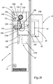
- a magnetic device 42 is arranged in the bolt holder ( Figures 2 to 2c ). In the case shown, this has a permanent magnet which is designed in such a way that, in the closed position of the door, it pulls the locking element 32 into the locking position as soon as the unlocking holding device 34 of the locking element 32 is unlocked and the locking element 32 can thus be released ( Figure 2b ).
- the locking holding device 35 arrests the locking element 32 in the locking position ( Figure 2c ).
- the locking holding device 35 is electrically switched accordingly.
- the prerequisite for the unlocking process is that the locking holding device 35 is first electrically activated.
- the unlocking stroke of the locking element 32 is shown in FIG Embodiment achieved by the fact that when the sash 6 is opened manually, the locking element 32 via an outlet bevel formed at the free end of the locking element 32 ( Figures 4 to 4d ), disengages. In the illustrated embodiment, it is the use on a hinged door.
- the first spring 33 acts on the locking element 32 in the unlocking direction. As soon as the locking element 32 is out of engagement of the magnetic device 42 due to the opening position of the sash 6, the complete retraction movement of the locking element 32 into its unlocking position takes place under the action of the first spring 33. In the unlocking position with the locking element 32 fully retracted, the locking element 32 comes into engagement with the pin 32s with the armature 34a of the unlocking holding device 34. The unlocking holding device 34 locks the locking element 32s in the locked position of the armature 34a ( Fig. 2a ).
- the locking device 1 can also be used on a swing door.
- the locking element 32 must also have an inlet bevel in addition to the run-out bevel ( Fig. 4 ).
- the locking element 32 then has a symmetrical design at its end, so that the door leaf 6, as a swing door leaf, can be rotated both to the left and to the right from the locking position.
- the unlocking holding device 34 is activated, the locking element 32 acts in the manner of a resilient latch which centers the door leaf 6 in the closed position, in that the locking element 32 is extended in the closed position by the magnetic device 42.
- a resilient latch can be provided in addition to the locking element 3, so that the swing door can be operated can without the unlocking holding device 34 acting on the locking element being released. The centering of the swing door in the zero position then takes place exclusively via the resilient latch when the locking element is held locked in the unlocked position.
- the bolt assembly 3 can also be mounted in the horizontal spar of the frame 5 and the bolt receiving device 4 can be mounted in a corresponding position on the sash side.
- the locking device 1 can be installed in reverse assembly, namely the bolt assembly 3 on the sash side and the bolt receiving device 4 on the frame side.
- the magnetic device 41 is designed as an electromagnetic device.
- the locking element 32 can also be formed without an outlet bevel or an inlet bevel.
- Fig. 3 shows other possible uses of modified designs.
- the locking element 32 is to be designed with an outlet bevel or inlet bevel arranged on the end face.
- the Figures 4b, 4c, 4d show such designs.
- the bolt assembly 3 can be arranged on the frame side on the upper spar, preferably in the running rail of the sliding sash and the bolt receiving device 4 on the sash side.
- the reverse assembly is also possible here.
- the direction of movement of the sliding door is in the Figure 3 represented by an arrow.
- Figure 4d shows an embodiment of a locking element 32, which can be used universally both for swing doors and for sliding doors by having an outlet bevel and / or an inlet bevel for a sliding door and an outlet bevel and / or an inlet bevel for a revolving door.
- the locking elements 32 shown with inlet slopes and outlet slopes can also be used with conventional locking devices and conventional electric door openers. This also applies in particular to the universal locking elements Figure 4d that can be used for both sliding and revolving doors. Furthermore, this also applies to modified locking elements that only have inlet bevels or only outlet bevels, specifically for revolving doors or for sliding doors.
- These conventional locking devices can have a lock case which can be mounted on or in the frame or on or in the wing and in which a preferably conventional lock mechanism is mounted. In such designs, the lock case can be designed as a lock case of a mortise lock for internal assembly.
- the lock mechanism can control a bolt and / or a latch in all of these different designs, the bolt and / or the latch being extendable and / or extended in the bolt receptacle in the closed position of the door and in the open position of the door the bolt and / or the latch are or is pulled into the lock case.
- Preferred embodiments provide that at least the bolt is retracted in the lock case.
- the bolt and / or the latch can interact with the magnetic device 42 arranged in the bolt receptacle 41.
- another locking device can be provided that the Bolt and / or the latch is moved into the locking position.
- This other locking device can be designed, for example, as an electric motor device or as a spring device or as a mechanical, manually operable handle device, preferably mounted in a lock socket of the lock mechanism.
- the lock mechanism can be equipped with an electrically switchable locking holding device 35 and / or an electrically switchable unlocking holding device 34, preferably arranged in the lock case.
- the electrically switchable locking retaining device 35 and / or the electrically switchable unlocking retaining device 34 can also be arranged outside the lock case in or adjacent to the bolt receiving device 4.
- designs with locking devices with preferably conventional lock mechanisms are provided which have no electrically switchable locking holding device 35 and no electrically switchable unlocking holding device 34.
- the locking element 32 is designed with an outlet slope and / or an inlet slope and, in the case of the outlet slope, the door can be opened by pushing open and / or pulling the door open, interacting with the locking mechanism, without this it is necessary to actively retract the locking element via a separate actuating device.
- locking holding device 35 In the exemplary embodiments according to the invention, the components described in the description of the figures for the exemplary embodiments shown in the figures are: locking holding device 35, unlocking holding device 34 and the run-in bevel of the locking element 32 are only optional. It is essential in the embodiments according to the invention that the locking device has an outlet slope and a magnetic device. It is essential here that, in order to establish the locking position of the locking element 32, the locking receptacle device 4 and the locking assembly 3 are assigned to one another in such a way that the locking element 32 can be moved into the locking position and brought into engagement with the locking receptacle 41 by the action of magnetic force by the magnetic device 42.
- the locking element 32 can be brought out of engagement of the magnetic device 42 in that the locking element 32 and / or the locking receptacle 41 has an outlet slope and the locking element 32 and the locking receptacle 41 are assigned to one another in such a way that the locking element 32 overlaps the run-out bevel is acted upon in the unlocking direction by the interaction of the bolt receptacle 41 and the bolt element 32 during the opening process of the door, ie when the sash is moved in the opening direction.
Landscapes
- Physics & Mathematics (AREA)
- Electromagnetism (AREA)
- Engineering & Computer Science (AREA)
- Mechanical Engineering (AREA)
- Lock And Its Accessories (AREA)
- Wing Frames And Configurations (AREA)
- Gates (AREA)
Description
- Die Erfindung betrifft eine Verriegelungseinrichtung mit den Merkmalen des Oberbegriffs des Patentanspruchs 1.
- Aus der
EP 2 594 713 A1 ist eine Riegelbaugruppe bekannt mit einem verschiebbaren Riegel, der über einen Elektromotor von einer Entriegelungsposition in eine Verriegelungsstellung bewegt werden kann. Durch einen Elektromagneten wird der Riegel in der Verriegelungsstellung arretiert. Das Einfahren des Riegels erfolgt mittels einer Rückstellfeder. - Aus der
US 2014/191515 A1 ist eine Verriegelungseinrichtung der eingangs genannten Art bekannt. Über eine Ein- und Auslaufschräge kann der Öffnungs- und Schließvorgang der Tür durch reines Drücken bzw. Ziehen erfolgen. - Aus der
US 2014/319850 A1 ist eine Verriegelungseinrichtung bekannt, bei der der Riegel über eine Feder immer in der eingezogenen Stellung gehalten wird, und bei geschlossener Tür durch eine Magneteinrichtung in die Verriegelungsstellung gezogen wird. Der Riegel ist voll umlaufend konisch ausgebildet. Die Schrägen dienen dazu, dass der Riegel leichter in die Riegelaufnahme eingreifen kann. - Aufgabe der Erfindung ist es, eine Verriegelungseinrichtung mit einem einfachen Aufbau zur Verfügung zu stellen, bei der sichergestellt ist, dass zur Ausbildung der Entriegelungsstellung des Riegelelements das Riegelelement aus dem Eingriff der Magneteinrichtung bringbar ist.
- Die Aufgabe wird mit dem Gegenstand des Anspruchs 1 gelöst. Bei der erfindungsgemäßen Lösung handelt es sich um eine Verriegelungseinrichtung für einen in einem Rahmen bewegbar gelagerten Flügel, vorzugsweise Verriegelungseinrichtung für eine Tür in einem Gebäude. Die Verriegelungseinrichtung umfasst eine am Rahmen oder am Flügel montierbare Riegelbaugruppe und eine am Flügel bzw. am Rahmen montierbare Riegelaufnahmeeinrichtung, wobei vorgesehen ist, dass die Riegelbaugruppe ein beweglich gelagertes, als Falle oder Riegel ausgebildetes Riegelelement aufweist. Wesentlich dabei ist, dass die Riegelaufnahmeeinrichtung eine das Riegelelement in der Verriegelungsstellung aufnehmende Riegelaufnahme aufweist und die Riegelaufnahmeeinrichtung und das Riegelelement eine Magneteinrichtung aufweist. Zur Ausbildung der Verriegelungsstellung des Riegelelements sind die Riegelaufnahmeeinrichtung und die Riegelbaugruppe derart einander zugeordnet, dass das Riegelelement durch magnetische Krafteinwirkung der Magneteinrichtung in die Verriegelungsstellung bewegbar und in einen Eingriff mit der Riegelaufnahme bringbar ist. Zur Ausbildung einer Entriegelungsstellung des Riegelelements ist das Riegelelement aus dem Eingriff der Magneteinrichtung bringbar, indem das Riegelelement und/oder die Riegelaufnahme eine Auslaufschräge aufweist und das Riegelelement und die Riegelaufnahme derart einander zugeordnet sind, dass das Riegelelement über die Auslaufschräge durch Zusammenwirken von Riegelaufnahme und Riegelelement beim Öffnungsvorgang in Entriegelungsrichtung beaufschlagt wird.
- Wesentlich ist, dass die Magneteinrichtung der Riegelaufnahmeeinrichtung als Elektromagnet ausgebildet ist und der Elektromagnet umpolbar und das Riegelelement einen Permanentmagnet aufweist. Durch das Umpolen des Elektromagneten kann ein Riegelelement, welches sich in Verriegelungsstellung befindet, in die Entriegelungsstellung überführt werden, indem der Elektromagnet den Permanentmanget des Riegelelements abstößt.
- Was den Verriegelungsvorgang betrifft, ist bei der erfindungsgemäßen Lösung wesentlich, dass zur Ausbildung der Verriegelungsstellung des Riegelelements die Riegelaufnahmeeinrichtung und die Riegelbaugruppe derart einander zugeordnet sind, dass das Riegelelement durch magnetische Krafteinwirkung in die Verriegelungsstellung bewegbar und in einen Eingriff mit der Riegelaufnahme bringbar ist. Es sind auch Ausführungen möglich, bei denen das Riegelelement U-förmig ausgebildet ist, und einen Teil der Türe umgreift, wodurch die Riegelaufnahme durch das Eingreifen der Tür in das Riegelelement ausgebildet wird.
- Der Begriff Verriegelungseinrichtung ist breit zu verstehen, d.h. das Riegelelement kann als Riegel oder auch als Falle, vorzugsweise federnd gelagerte Falle, ausgebildet sein. In der Verriegelungsstellung des Riegelelements kann eine einbruchsichere Verriegelung des Flügels vorliegen oder auch nur eine Arretierung des Flügels. Die Verriegelungseinrichtung kann so montiert werden, dass die Verriegelungsstellung in der Schließstellung des Flügels vorliegt. Es kann jedoch auch eine Montage der Verriegelungseinrichtung möglich sein, bei der die Verriegelungsstellung des Riegelelements in der Offenstellung des Flügels vorliegt.
- Bevorzugte Anwendungen der Verriegelungseinrichtung sind Anwendungen an Türen, vorzugsweise Gebäudetüren. Die Tür kann vorzugsweise mit einem in einem Rahmen schwenkbar gelagerten Flügel ausgebildet sein. Die Tür kann aber auch als ein für einen Rahmen schiebbar gelagerter Flügel ausgebildet sein.
- Es kann vorgesehen sein, dass die Riegelbaugruppe vorzugsweise seitlich am Rahmen oder am Flügel angeordnet ist und die Riegelaufnahmeeinrichtung entsprechend gegenüberliegend vorzugsweise seitlich am Flügel oder am Rahmen. Es sind Ausführungen möglich, bei denen die Riegelbaugruppe im Bereich des oberen horizontalen Holms des Türrahmens oder am oberen Bereich des Flügels montiert ist und die Riegelaufnahmeeinrichtung entsprechend gegenüberliegend am oberen Bereich des Flügels oder im Bereich des oberen horizontalen Holms des Türrahmens.
- Bei besonders bevorzugten Ausführungen der erfindungsgemäßen Verriegelungseinrichtung handelt es sich um ein Schloss mit Magneteinrichtung in der Riegelaufnahme und Auslaufschräge am Riegelelement oder an der Riegelaufnahme. Es kann sich vorzugsweise um ein Schloss zum universellen Einsatz an Anschlagtüren, Pendeltüren und Schiebetüren handeln. Das Schloss ist als ein mechanisches Schloss mit Magneteinrichtung ausführbar, jedoch auch mit elektrischen Zusatzkomponenten.
- Es kann vorgesehen sein, dass das Riegelelement eine Einlaufschräge aufweist.
- Es kann vorgesehen sein, dass das Riegelelement eine Federeinrichtung aufweist, die das in außer Eingriff der Magneteinrichtung stehendes Riegelelement in die Entriegelungsstellung beaufschlagt.
- Es kann vorgesehen sein, dass das Riegelelement oder/und die Magneteinrichtung und/oder die Riegelaufnahme federnd gelagert ist bzw. sind.
- Es kann vorgesehen sein, dass die federnde Lagerung eine Federeinrichtung aufweist, durch die Riegelelement oder/und die Magneteinrichtung und/oder die Riegelaufnahme in Verriegelungsrichtung beaufschlagt ist.
- In einer weiteren vorteilhaften Ausführung kann vorgesehen sein, dass die Riegelaufnahme eine Auslaufschräge und/oder eine Einlaufschräge aufweist.
- Es kann vorgesehen sein, dass zur Ausbildung und/oder Arretierung der Verriegelungsstellung die Riegelbaugruppe und/oder die Riegelaufnahmeeinrichtung eine elektrisch schaltbare Verriegelungs-Halteeinrichtung aufweist. Vorzugsweise greift in der Verriegelungsstellung das Riegelelement in die Riegelaufnahmeeinrichtung ein. Es sind aber auch Ausführungen möglich, bei denen das Riegelelement in ver Verriegelungsstellung einen Teil des Flügels umgreift.
- Es kann vorgesehen sein, dass die elektrisch schaltbare Verriegelungs-Halteeinrichtung einen Elektromagneten aufweist.
- Es kann vorgesehen sein, dass zur Ausbildung und/oder Arretierung der Entriegelungsstellung die Riegelbaugruppe eine elektrisch schaltbare Entriegelungs-Halteeinrichtung aufweist, die das Riegelelement in seiner Entriegelungsstellung arretiert. Vorzugsweise weist die elektrisch schaltbare Entriegelungs-Halteeinrichtung einen Elektromagneten und/oder einen Anker auf. Der Anker kann so ausgebildet sein, dass er einen Teil des Riegelelements umgreift, und das Riegelelement dadurch in seiner Entriegelungsstellung schaltbar arretiert oder freigibt.
- Es kann vorgesehen sein, dass das Riegelelement oder zumindest ein Abschnitt des Riegelelements aus magnetisierbarem Material oder permanentmagentischem Material ausgebildet ist, oder vorzugsweise als Elektromagnet ausgebildet ist.
- Es kann vorgesehen sein, dass die Riegelbaugruppe in einem Schlosskasten gelagert ist, der in oder auf dem Rahmen oder in oder auf dem Flügel montierbar ist.
- In einer weiteren vorteilhaften Ausführung kann vorgesehen sein, dass in dem Schlosskasten eine Schlossmechanik gelagert ist, wobei die Schlossmechanik zur Steuerung eines Riegels und/oder einer Falle ausgebildet ist.
- Es kann vorgesehen sein, dass der Riegel und/oder die Falle als das mit der Magneteinrichtung der Riegelaufnahmeeinrichtung zusammenwirkende Riegelelement ausgebildet ist/sind.
- Es kann vorzugsweise vorgesehen sein, dass die Auslaufschräge an dem Riegelelement und/oder der Riegelaufnahme derart ausgebildet ist, dass durch die Schwenkbewegung und/oder Öffnungsbewegung und/oder beim Öffnungsvorgang des Flügels beim Zusammenwirken von Riegelelement und Riegelaufnahme das Riegelelement in Entriegelungsstellung bringbar ist.
- Es kann vorgesehen sein, dass das Riegelelement zur Ausbildung der Entriegelungsstellung derart ausgebildet ist, dass das Riegelelement durch die Auslaufschräge beim Zusammenwirken von Riegelelement und Riegelaufnahme ohne Hub des Flügels in die Entriegelungsstellung bringbar ist.
- Es kann somit vorgesehen sein, dass zur Ausbildung der Entriegelungsstellung des Riegelelements das Riegelelement bei Bewegung der Tür in Türöffnungsrichtung mit der Auslaufschräge zusammenwirkt. Bei Anschlagtüren oder Pendeltüren ist die Schwenkbewegung des Flügels die Türöffnungsrichtung. Bei Schiebetüren ist die Türöffnungsrichtung die Schiebebewegung, vorzugsweise horizontale Schiebebewegung des Flügels.
- Besonders vorteilhaft sind die Ausführungen, die vorsehen, dass das Riegelelement zur Ausbildung der Entriegelungsstellung ohne Hub des Flügels und/oder der Riegelbaugruppe und/oder der Riegelaufnahmeeinrichtung in die Entriegelungsstellung bringbar ist. Dabei wird das Riegelelement bei einer Hubbewegung nicht durch die Auslaufschräge an dem Riegelelement und/oder der Riegelaufnahme in Entriegelungsstellung beaufschlagt.
- Weitere Vorteile und Merkmale der Erfindung ergeben sich aus der nachfolgenden Beschreibungen von Ausführungsbeispielen anhand der Zeichnungen. Die Zeichnungen zeigen:
- Fig. 1
- Anordnung der Verrieglungseinrichtung in einer Anschlag-Drehtür;
- Fig. 2
- Verrieglungseinrichtung in Entriegelungsstellung mit in der Entriegelungsstellung nicht arretiertem Riegelelement 32;
- Fig. 2a
- Verrieglungseinrichtung in Entriegelungsstellung mit in der Entriegelungsstellung arretiertem Riegelelement 32;
- Fig. 2b
- Verrieglungseinrichtung in Verriegelungsstellung mit in der Verriegelungsstellung nicht arretiertem Riegelelement 32;
- Fig. 2c
- Verrieglungseinrichtung in Verriegelungsstellung mit in der Verriegelungsstellung arretiertem Riegelelement 32;
- Fig. 3
- Anordnung der Verrieglungseinrichtung in einer Schiebetür;
- Fig. 4
- ein Riegelelement zum Einsatz in einer Pendeltür;
- Fig. 4a
- ein Riegelelement zum Einsatz in einer Anschlagdrucktür;
- Fig. 4b
- ein Riegelelement zum universellen Einsatz in einer linken und rechten Schiebetür;
- Fig. 4c
- ein Riegelelement zum Einsatz in einer linken oder rechten Schiebetür;
- Fig. 4d
- ein Riegelelement zum universellen Einsatz in einer Pendeltür und einer Schiebetür.
- Im Folgenden ist anhand von zeichnerischen Darstellungen die Erfindung näher erläutert. Dabei zeigt
Fig. 1 ein erfindungsgemäßes Ausführungsbeispiel der Verrieglungseinrichtung 1 montiert an einer Anschlag-Drehtür.Fig. 2 zeigen den Aufbau der Verrieglungseinrichtung 1 in vergrößerter Darstellung. - Bei dem Ausführungsbeispiel in
Fig. 1 umfasst die Anschlag-Drehtür einen Rahmen 5 und einen Flügel 6, der an Bändern 2 drehbar um die vertikale Türachse gelagert ist. Die am Rahmen montierte Verrieglungseinrichtung 1 umfasst eine Riegelbaugruppe 3 und eine Riegelaufnahmeeinrichtung 4. Die Riegelbaugruppe 3 ist im dargestellten Fall seitlich am Rahmen 5 montiert. Die Montage ist vorzugsweise im Rahmen 5 innenliegend ausgeführt. Die Riegelaufnahmeeinrichtung 4 ist flügelseitig der Riegelbaugruppe 3 gegenüberliegend montiert, ebenfalls vorzugsweise innenliegend. - Die Riegelbaugruppe 3 weist ein Gehäuse 31 auf mit einem darin in vertikaler Richtung verschiebbar gelagerten Riegelelement 32, das durch eine erste Feder 33 in Entriegelungsstellung beaufschlagt ist. In der Entriegelungsstellung ist der Riegelelement 32 in das Gehäuse 31 eingezogen und steht mit seinem freien Ende nicht über das Gehäuse 31 vor (
Fig. 2 und2a ). Die erste Feder 33 ist im dargestellten Fall als Schenkelfeder ausgebildet, die an einem gehäusefesten Lagerpunkt 33d drehbar gelagert ist und stützt sich mit ihrem ersten Schenkel 33a an einem Gehäuseanschlag und mit ihrem zweiten Schenkel 33b an einem Mitnehmer 32m des Riegelelements 32 ab. - In dem Gehäuse 31 ist als weitere Komponente eine elektrische schaltbare Entriegelungs-Halteeinrichtung 34 angeordnet. Diese weist einen Elektromagneten 34m auf, der mit einem am Riegelelement 32 angeordneten Stift 32s zusammenwirkt. Der Elektromagneten 34m umfasst eine Spule 34s die mit einem schwenkbar im Gehäuse 31 gelagerten Anker 34a zusammenwirkt. Der Anker 34a ist als einarmiger Hebel um eine Drehachse 34d derart schwenkbar gelagert, dass er eine am Elektromagneten 34m anliegende Freigabestellung (
Fig. 2 ) und eine, im dargestellten Fall im Uhrzeigersinn geschwenkte, Sperrstellung (Fig. 2a ) einnehmen kann. Zwischen dem Elektromagneten 34m und dem Anker 34a ist eine Schraubendruckfeder angeordnet, der den Anker 34a in seine Sperrstellung (Fig. 2a ) beaufschlagt. Der Anker 34a weist einen vorspringenden Anschlag auf, mit dem er in der Sperrstellung des Ankers 34a den Stift 32s hintergreift und damit das Riegelelement 32 in seiner Entriegelungsstellung arretiert. In der Freigabestellung des Ankers 34a ist der Anker 34a gegen Uhrzeigersinn geschwenkt und damit außer Eingriff mit dem Stift 32s. - Als weitere Komponente ist im Gehäuse 31 eine Verriegelungs-Halteeinrichtung 35 angeordnet. Sie umfasst einen ersten einarmigen Hebel 35h. Dieser erste Hebel 35h ist in einen Lager 32d am Riegelelement 32 schwenkbar gelagert und weist in der Mitte einen Haltebolzen 35n und an seinem freien Ende eine Rolle 35r auf (
Fig. 2 und2a ). In dem Riegelelement ist eine zweite Feder 35f angeordnet, die im Lager 32d gelagert ist, und sich mit ihrem ersten Lagerarm am Riegelelement 32 abstützt und mit ihrem zweiten Lagerarm am Haltebolzen 35n des ersten Hebels 35h abstützt. Der erste Hebel 35h wird beim Ausfahren des Riegelelements 32 durch die zweite Feder 35f derart beaufschlagt, dass die Rolle 35r des ersten Hebels 35h an einer Linearführung in der stulpabgewandten Innenseite des Gehäuses 31 entlangläuft (Fig. 2b und2c ), in der Darstellung inFig. 2 dreht sich der erste Hebel 35h in Uhrzeigersinn. Zusätzlich umfasst die Verriegelungs-Halteeinrichtung 35 einen zweiten einarmigen Hebel 35i, der im Gehäuse 31 im Lagerpunkt 33d drehbar gelagert ist. Der zweite Hebel 35i weist in der Mitte eine Einkerbung 35k und an seinem freien Ende eine Halteplatte 35p auf. Im dargestellten Fall schwenkt der zweite Hebel 35i zur Sicherung des ersten Hebels 35h gegen den Uhrzeigersinn (Fig. 2b ) und wird durch den zweiten Elektromagneten 35m der Verriegelungs-Halteeinrichtung 35 durch Einwirkung auf die Halteplatte 35p in dieser geschwenkten Position gehalten (Fig. 2c ). In dieser Position erfolgt der Eingriff des Haltebolzens 35n des ersten Hebels 35h in die Einkerbung 35k des zweiten Hebels 35i. Die Verriegelungs-Halteeinrichtung 35 kann so ausgebildet sein, dass sie im Ruhestrom oder Arbeitsstrom betrieben werden kann. Für den Betrieb im Ruhestrom wird der zweite Elektromagnet 35m mit Spannung versorgt, um den zweiten Hebel 35i zur Sicherung des ersten Hebels 35h zu verschwenken. Im Arbeitsstrom-Betrieb bewegt der zweite Elektromagnet 35m durch Bestromung seiner Spule den zweiten Hebel 35i, um die Sicherung des ersten Hebels 35h aufzuheben, wobei der zweite Hebel 35i im Arbeitsstrom-Betrieb so ausgebildet ist dass er durch eine Federbeaufschlagung den ersten Hebel 35h dauerhaft sichert. Im Arbeitsstrom-Betrieb kann für eine Notfallentriegelung z.B. ein Profilzylinder unterhalb des zweiten Elektromagneten 35m im Gehäuse 31 angeordnet sein, welcher über einen Schieber oder ein Gestänge auf den zweite Hebel 35i zur Freigabe des ersten Hebels 35h einwirkt. - Die am Flügel gelagerte Riegelaufnahmeeinrichtung 4 weist eine im Stuplblech angeordnete Riegelaufnahme 41 auf, in die das Riegelelement in die Verriegelungsstellung eingreift (
Fig. 2b und2c ). In der Riegelaufnahme ist eine Magneteinrichtung 42 angeordnet (Fig. 2 bis 2c ). Diese weist im dargestellten Fall einen Permanentmagneten auf, der derart ausgebildet ist, dass er in der Schließstellung der Tür das Riegelelement 32 in die Verriegelungsposition in Eingriff zieht, sobald die Entriegelungs-Halteeinrichtung 34 des Riegelelements 32 freigeschaltet ist, und damit das Riegelelement 32 freigebbar ist (Fig. 2b ). Um das Riegelelement 32 in der Verriegelungsstellung sicher zu halten arretiert die Verriegelungs-Halteeinrichtung 35 das Riegelelement 32 in der Verriegelungsstellung (Fig. 2c ). Hierfür wird die Verriegelungs-Halteeinrichtung 35 entsprechend elektrisch geschaltet. - Für den Entriegelungsvorgang ist die Voraussetzung, dass zunächst die Verriegelungs-Halteeinrichtung 35 elektrisch freigeschalten wird. Der Entriegelungshub des Riegelelements 32 wird im dargestellten Ausführungsbeispiel dadurch erreicht, dass beim manuellen Öffnen des Flügels 6 das Riegelelement 32 über eine am freien Ende des Riegelelements 32 ausgebildete Auslaufschräge (
Fig. 4 bis 4d ), außer Eingriff kommt. Bei dem dargestellten Ausführungsbeispiel handelt es sich um den Einsatz an einer Anschlag-Drehtür. - Die erste Feder 33 beaufschlagt das Riegelelement 32 in Entriegelungsrichtung. Sobald das Riegelelement 32 aufgrund der Öffnungsstellung des Flügels 6 außer Eingriff der Magneteinrichtung 42 ist, erfolgt unter Wirkung der ersten Feder 33 die vollständige Einfahrbewegung des Riegelelements 32 in seine Entriegelungsstellung. In der Entriegelungsstellung bei vollständig eingezogenem Riegelelements 32 kommt das Riegelelement 32 mit dem Stift 32s in Eingriff mit dem Anker 34a der Entriegelungs-Halteeinrichtung 34. Die Entriegelungs-Halteeinrichtung 34 arretiert in der Sperrstellung des Ankers 34a das Riegelelemente 32s (
Fig. 2a ). - Bei einem abgewandelten Ausführungsbespielt kann die Verriegelungseinrichtung 1 auch an einer Pendeltüre eingesetzte werden. In diesen Fall muss das Riegelelement 32 zusätzlich zu der Auslaufschräge auch eine Einlaufschräge aufweisen (
Fig. 4 ). Das Riegelelement 32 weist an seinem Ende dann eine symmetrische Gestaltung auf, so dass der Türflügel 6 als Pendeltürflügel aus der Verriegelungsstellung sowohl nach links als auch nach rechts gedreht werden kann. Das Riegelelement 32 wirkt bei freigeschalteter Entriegelungs-Halteeinrichtung 34 in Art einer federnden Falle, die den Türflügel 6 in der Schließlage zentriert, indem das Riegelelement 32 in der Schließlage durch die Magneteinrichtung 42 ausgefahren wird. Bei besonderen Ausführungen der Pendeltüranwendung kann zusätzlich zu dem Riegelelement 3 eine federnde Falle vorgesehen sein, so dass der Pendeltürbetrieb erfolgen kann, ohne dass die auf das Riegelelement einwirkende Entriegelungs-Halteeinrichtung 34 freigeben ist. Die Zentrierung der Pendeltür in der Nulllage erfolgt dann ausschließlich über die federnde Falle bei in Entriegelungsstellung arretiert gehaltenem Riegelelement. - Bei abgewandelten Ausführungen kann die Riegelbaugruppe 3 auch im horizontalen Holm des Rahmens 5 montiert sein und die Riegelaufnahmeeinrichtung 4 in entsprechender Position flügelseitig montiert sein.
- Ferner kann die Verriegelungseinrichtung 1 bei umgekehrter Montage eingebaut werden, nämlich die Riegelbaugruppe 3 flügelseitig und die Riegelaufnahmeeinrichtung 4 rahmenseitig.
- Ferner sind abgewandelte Ausführungen möglich, bei denen die Magneteinrichtung 41 als elektro-magnetische Einrichtung ausgebildet ist. Bei diesen Ausführungen kann das Riegelelement 32 auch ohne Auslaufschräge bzw. Einlaufschräge eingebildet sein.
- Weitere Anwendungsmöglichkeiten von abgewandelten Ausführungen sind an Schiebetüren mögliche wie in
Fig. 3 gezeigt. In diesen Fall ist das Riegelelement 32 mit stirnseitig angeordneter Auslaufschräge bzw. Einlaufschräge auszuführen. DieFiguren 4b, 4c, 4d zeigen solche Ausführungen. Auch in diesen Fall kann die Riegelbaugruppe 3 rahmenseitig am oberen Holm vorzugsweise in der Laufschiene des Schiebeflügels angeordnet sein und die Riegelaufnahmeeinrichtung 4 flügelseitig. Auch hier ist die umgekehrte Montage möglich. Die Bewegungsrichtung der Schiebetür ist in derFigur 3 durch einen Pfeil dargestellt. -
Fig. 4d zeigt ein Ausführungsbeispiel eines Riegelelements 32, welches universell sowohl für Schwenktüren als auch für Schiebetüren einsetzbar ist, indem es eine Auslaufschräge und/oder eine Einlaufschräge für eine Schiebetür und eine Auslaufschräge und/oder eine Einlaufschräge für eine Drehtür aufweist. - Die dargestellten Riegelelemente 32 mit Einlaufschrägen und Auslaufschrägen sind auch mit herkömmlichen Verriegelungseinrichtungen und herkömmlichen elektrischen Türöffnern einsetzbar. Dies gilt insbesondere auch für universelle Riegelelemente der
Fig. 4d , die sowohl für Schiebetüren als auch für Drehtüren einsetzbar sind. Ferner gilt dies auch für abgewandelte Riegelelemente, die lediglich Einlaufschrägen oder lediglich Auslaufschrägen aufweisen, und zwar jeweils für Drehtüren oder für Schiebetüren. Diese herkömmlichen Verriegelungseinrichtungen können einen auf oder in dem Rahmen oder auf oder in dem Flügel montierbaren Schlosskasten aufweisen, in welchem eine vorzugsweise herkömmliche Schlossmechanik gelagert ist. Der Schlosskasten kann bei solchen Ausführungen für innenliegende Montage als Schlosskasten eines Einsteckschlosses ausgebildet sein. Die Schlossmechanik kann bei all diesen verschiedenen Ausführungen einen Riegel und/oder eine Falle steuern, wobei der Riegel und/oder die Falle in der Schließstellung der Tür in die Riegelaufnahme ausfahrbar und/oder in dieser ausgefahren sind bzw. ist und in der Offenstellung der Tür der Riegel und/oder die Falle in den Schlosskasten eingezogen sind bzw. ist. Bevorzugte Ausführungen sehen vor, dass zumindest der Riegel im Schlosskasten eingezogen ist. Der Riegel und/oder die Falle können bzw. kann mit der in der Riegelaufnahme 41 angeordneten Magneteinrichtung 42 zusammenwirken. Anstelle der Magneteinrichtung 42 kann auch eine andere Verriegelungseinrichtung vorgesehen sein, die den Riegel und/oder die Falle in die Verriegelungsstellung bewegt. Diese andere Verriegelungseinrichtung kann z.B. als elektrische Motoreinrichtung oder als Federeinrichtung ausgebildet sein oder als mechanische, manuell betätigbare Handhabeeinrichtung, vorzugsweise in einer Schlossnuss der Schlossmechanik gelagert. - Im Falle von Ausführungen als herkömmliche Verrieglungseinrichtung mit Schlossmechanik in einem Schlosskasten kann die Schlossmechanik mit einer elektrisch schaltbaren Verriegelungs-Halteeinrichtung 35 und/oder einer elektrisch schaltbaren Entriegelungs-Halteeinrichtung 34 ausgestattet sein, vorzugsweise im Schlosskasten angeordnet. Bei abgewandelten Ausführungen können bzw. kann die elektrisch schaltbare Verriegelungs-Halteeinrichtung 35 und/oder die elektrisch schaltbaren Entriegelungs-Halteeinrichtung 34 auch außerhalb des Schlosskastens in oder angrenzend an die Riegelaufnahmeeinrichtung 4 angeordnet sein. Ferner sind Ausführungen mit Verriegelungseinrichtungen mit vorzugsweise herkömmlicher Schlossmechanik vorgesehen, die keine elektrisch schaltbare Verriegelungs-Halteeinrichtung 35 und keine elektrisch schaltbaren Entriegelungs-Halteeinrichtung 34 aufweisen. Besonders vorteilhaft ist bei den verschiedenen Ausführungen, dass das Riegelelement 32 mit einer Auslaufschräge und/oder einer Einlaufschräge ausgebildet ist und im Falle der Auslaufschräge ein Öffnen der Tür durch Aufdrücken und/oder Aufziehen der Tür unter Zusammenwirken mit der Riegelaufnahme möglich ist, ohne dass es erforderlich ist, das Riegelelement über eine separate Betätigungseinrichtung aktiv einzuziehen.
- Bei den erfindungsgemäßen Ausführungsbeispielen sind die in der Figurenbeschreibung zu den in den Figuren dargestellten Ausführungsbeispielen beschriebenen Komponenten: Verriegelungs-Halteeinrichtung 35, Entriegelungs-Halteeinrichtung 34 sowie die Einlaufschräge des Riegelelements 32 lediglich optional. Wesentlich bei den erfindungsgemäßen Ausführungen ist, dass die Verriegelungseinrichtung eine Auslaufschräge und eine Magneteinrichtung aufweist. Wesentlich ist hierbei, dass zum Ausbilden der Verriegelungsstellung des Riegelelements 32 die Riegelaufnahmeeinrichtung 4 und die Riegelbaugruppe 3 derart einander zugeordnet sind, dass das Riegelelement 32 durch magnetische Krafteinwirktun der Magneteinrichtung 42 in die Verriegelungsstellung bewegbar und in einen Eingriff mit der Riegelaufnahme 41 bringbar ist. Zum Ausbilden der Entriegelungsstellung des Riegelelements 32 ist das Riegelelement 32 aus dem Eingriff der Magneteinrichtung 42 bringbar, indem das Riegelelement 32 und/oder die Riegelaufnahme 41 eine Auslaufschräge aufweist und das Riegelelement 32 und die Riegelaufnahme 41 derart einander zugeordnet sind, dass das Riegelelement 32 über die Auslaufschräge durch Zusammenwirken von Riegelaufnahme 41 und Riegelelement 32 beim Öffnungsvorgang der Tür, d.h. wenn der Flügel in Öffnungsrichtung bewegt wird, in Entriegelungsrichtung beaufschlagt wird.
-
- 1
- Verriegelungseinrichtung
- 2
- Band
- 3
- Riegelbaugruppe
- 4
- Riegelaufnahmeeinrichtung
- 5
- Rahmen
- 6
- Flügel
- 31
- Gehäuse
- 32
- Riegelelement
- 32m
- Mitnehmer
- 32s
- Stift
- 32d
- Lager im Riegel
- 33
- erste Feder
- 33d
- Lagerpunkt
- 33a
- erster Schenkel
- 33b
- zweiter Schenkel
- 34
- Entriegelungs-Halteeinrichtung
- 34a
- Anker
- 34m
- Elektro-Magnet der Entriegelungs-Halteeinrichtung
- 34d
- Drehachse
- 34s
- Spule
- 35
- Verriegelungs-Halteeinrichtung
- 35h
- erster Hebel
- 35i
- zweiter Hebel
- 35r
- Rolle
- 35k
- Einkerbung
- 35n
- Haltebolzen
- 35f
- zweite Feder
- 35p
- Halteplatte
- 35m
- zweiter Elektromagnet
- 41
- Riegelaufnahme
- 42
- Magneteinrichtung
Claims (13)
- Verriegelungseinrichtung (1) für einen in einem Rahmen (5) bewegbar gelagerten Flügel (6), vorzugsweise Verriegelungseinrichtung (1) für eine Tür in einem Gebäude,umfassend eine am Rahmen (5) oder am Flügel (6) montierbare Riegelbaugruppe (3) und eine am Flügel (6) bzw. am Rahmen (5) montierbare Riegelaufnahmeeinrichtung (4),wobei vorgesehen ist,- dass die Riegelbaugruppe (3) ein beweglich gelagertes, als Falle oder Riegel ausgebildetes Riegelelement (32) aufweist, und- dass die Riegelaufnahmeeinrichtung (4) eine das Riegelelement (32) in der Verriegelungsstellung aufnehmende Riegelaufnahme (41) aufweist und die Riegelaufnahmeeinrichtung (4) und das Riegelelement (32)eine Magneteinrichtung (42) aufweist, und- dass zur Ausbildung der Verriegelungsstellung des Riegelelements (32) die Riegelaufnahmeeinrichtung (4) und die Riegelbaugruppe (3) derart einander zugeordnet sind, dass das Riegelelement (32) durch magnetische Krafteinwirkung der Magneteinrichtung (42) in die Verriegelungsstellung bewegbar und in einen Eingriff mit der Riegelaufnahme (41) bringbar ist,- dass zur Ausbildung einer Entriegelungsstellung des Riegelelements (32) das Riegelelement (32) aus dem Eingriff der Magneteinrichtung (42) bringbar ist, indem das Riegelelement (32) und/oder die Riegelaufnahme (41) eine Auslaufschräge aufweist und das Riegelelement (32) und die Riegelaufnahme (41) derart einander zugeordnet sind, dass das Riegelelement (32) über die Auslaufschräge durch Zusammenwirken von Riegelaufnahme (41) und Riegelelement (32) beim Öffnungsvorgang in Entriegelungsrichtung beaufschlagt wird, und- dass die Magneteinrichtung (41) der Riegelaufnahmeeinrichtung (4) als Elektromagnet ausgebildet ist bzw. sinddadurch gekennzeichnet,- dass der Elektromagnet umpolbar ausgebildet ist und das Riegelelement (32) einen Permanentmagnet aufweist.
- Verriegelungseinrichtung nach einem der vorangehenden Ansprüche, dadurch gekennzeichnet,
dass das Riegelelement (32) eine Einlaufschräge aufweist. - Verriegelungseinrichtung nach einem der vorangehenden Ansprüche, dadurch gekennzeichnet,
dass das Riegelelement (32) eine Federeinrichtung aufweist, die das in außer Eingriff der Magneteinrichtung (42) stehendes Riegelelement (32) in die Entriegelungsstellung beaufschlagt. - Verriegelungseinrichtung nach einem der Ansprüche 1 oder 2, dadurch gekennzeichnet,
dass das Riegelelement (32) oder/und die Magneteinrichtung (42) und/oder die Riegelaufnahme (41) federnd gelagert ist bzw. sind. - Verriegelungseinrichtung nach Anspruch 4,
dadurch gekennzeichnet,
dass die federnde Lagerung eine Federeinrichtung aufweist, durch die das Riegelelement (32) oder/und die Magneteinrichtung (42) und/oder die Riegelaufnahme (32) in Verriegelungsrichtung beaufschlagt ist. - Verriegelungseinrichtung nach einem der vorangehenden Ansprüche, dadurch gekennzeichnet,
dass zur Ausbildung und/oder Arretierung der Verriegelungsstellung die Riegelbaugruppe (3) und/oder die Riegelaufnahmeeinrichtung (4) eine elektrisch schaltbare Verriegelungs-Halteeinrichtung (35) aufweist. - Verriegelungseinrichtung nach Anspruch 6,
dadurch gekennzeichnet,
dass die elektrisch schaltbare Verriegelungs-Halteeinrichtung (35) einen Elektromagneten aufweist. - Verriegelungseinrichtung nach einem der vorangehenden Ansprüche, dadurch gekennzeichnet,
dass zur Ausbildung und/oder Arretierung der Entriegelungsstellung die Riegelbaugruppe eine elektrisch schaltbare Entriegelungs-Halteeinrichtung (34) aufweist, die das Riegelelement (32) in seiner Entriegelungsstellung arretiert. - Verriegelungseinrichtung nach Anspruch 8,
dadurch gekennzeichnet,
dass die elektrisch schaltbare Entriegelungs-Halteeinrichtung (34) einen Elektromagneten aufweist. - Verriegelungseinrichtung nach einem der vorangehenden Ansprüche,dadurch gekennzeichnet,dass die Riegelbaugruppe (3) in einem Schlosskasten gelagert ist, der in oder auf dem Rahmen (5) oder in oder auf dem Flügel (6) montierbar ist, wobei vorzugsweise vorgesehen ist,dass in dem Schlosskasten eine Schlossmechanik gelagert ist, wobei die Schlossmechanik zur Steuerung eines Riegels und/oder einer Falle ausgebildet ist, insbesonderedass der Riegel und/oder die Falle als das mit der Magneteinrichtung (42) der Riegelaufnahmeeinrichtung (4) zusammenwirkende Riegelelement (32) ausgebildet ist/sind.
- Verriegelungseinrichtung nach einem der vorangehenden Ansprüche, dadurch gekennzeichnet,
dass die Auslaufschräge an dem Riegelelement (32) und/oder der Riegelaufnahme (41) derart ausgebildet ist, dass durch die Schwenkbewegung und/oder Öffnungsbewegung und/oder beim Öffnungsvorgang des Flügels (6) beim Zusammenwirken von Riegelelement und Riegelaufnahme das Riegelelement (32) in Entriegelungsstellung bringbar ist. - Verriegelungseinrichtung nach einem der vorangehenden Ansprüche, dadurch gekennzeichnet,
dass das Riegelelement (32) zur Ausbildung der Entriegelungsstellung derart ausgebildet ist, dass das Riegelelement (32) durch die Auslaufschräge beim Zusammenwirken von Riegelelement und Riegelaufnahme ohne Hub des Flügels (6) in die Entriegelungsstellung bringbar ist. - Tür mit einem ortsfest anordenbaren Rahmen mit einem daran bewegbar gelagerten Flügel, wobei die Tür mit einer Verriegelungseinrichtung ausgestattet ist,
dadurch gekennzeichnet,
dass die Verriegelungseinrichtung nach einem der vorangehenden Ansprüche 1 bis 12 ausgebildet ist.
Applications Claiming Priority (7)
| Application Number | Priority Date | Filing Date | Title |
|---|---|---|---|
| DE102016117955 | 2016-09-23 | ||
| DE102016118258 | 2016-09-27 | ||
| DE102016123034.0A DE102016123034A1 (de) | 2016-09-23 | 2016-11-29 | Anschlagtür mit Auslaufschräge |
| DE102016123035.9A DE102016123035A1 (de) | 2016-09-23 | 2016-11-29 | Fluchttür mit Riegel mit Auslaufschräge |
| DE102016123032.4A DE102016123032A1 (de) | 2016-09-23 | 2016-11-29 | Verriegelungseinrichtung mit magnetischer Riegelaufnahme |
| DE102016123033.2A DE102016123033A1 (de) | 2016-09-23 | 2016-11-29 | Verriegelungseinrichtung mit magnetischer Riegelaufnahme und Auslaufschräge |
| DE102017100737.7A DE102017100737A1 (de) | 2017-01-16 | 2017-01-16 | Riegel für Drehtüren und/oder Flügeltüren |
Publications (2)
| Publication Number | Publication Date |
|---|---|
| EP3299548A1 EP3299548A1 (de) | 2018-03-28 |
| EP3299548B1 true EP3299548B1 (de) | 2021-12-01 |
Family
ID=59858960
Family Applications (6)
| Application Number | Title | Priority Date | Filing Date |
|---|---|---|---|
| EP17191017.7A Active EP3299547B1 (de) | 2016-09-23 | 2017-09-14 | Verriegelungseinrichtung mit magnetischer riegelaufnahme |
| EP17191044.1A Active EP3299550B1 (de) | 2016-09-23 | 2017-09-14 | Elektrischer türöffner für pendeltür mit magnetischem riegel |
| EP17191026.8A Not-in-force EP3299548B1 (de) | 2016-09-23 | 2017-09-14 | Verriegelungseinrichtung mit magnetischer riegelaufnahme und auslaufschräge |
| EP17191038.3A Active EP3299555B1 (de) | 2016-09-23 | 2017-09-14 | Riegel für drehtüren und/oder flügeltüren |
| EP17191036.7A Withdrawn EP3299560A1 (de) | 2016-09-23 | 2017-09-14 | Fluchttür mit riegel mit auslaufschräge |
| EP17191031.8A Withdrawn EP3299549A1 (de) | 2016-09-23 | 2017-09-14 | Anschlagtür mit auslaufschräge |
Family Applications Before (2)
| Application Number | Title | Priority Date | Filing Date |
|---|---|---|---|
| EP17191017.7A Active EP3299547B1 (de) | 2016-09-23 | 2017-09-14 | Verriegelungseinrichtung mit magnetischer riegelaufnahme |
| EP17191044.1A Active EP3299550B1 (de) | 2016-09-23 | 2017-09-14 | Elektrischer türöffner für pendeltür mit magnetischem riegel |
Family Applications After (3)
| Application Number | Title | Priority Date | Filing Date |
|---|---|---|---|
| EP17191038.3A Active EP3299555B1 (de) | 2016-09-23 | 2017-09-14 | Riegel für drehtüren und/oder flügeltüren |
| EP17191036.7A Withdrawn EP3299560A1 (de) | 2016-09-23 | 2017-09-14 | Fluchttür mit riegel mit auslaufschräge |
| EP17191031.8A Withdrawn EP3299549A1 (de) | 2016-09-23 | 2017-09-14 | Anschlagtür mit auslaufschräge |
Country Status (2)
| Country | Link |
|---|---|
| EP (6) | EP3299547B1 (de) |
| PL (3) | PL3299550T3 (de) |
Families Citing this family (6)
| Publication number | Priority date | Publication date | Assignee | Title |
|---|---|---|---|---|
| CN110439383A (zh) * | 2019-09-17 | 2019-11-12 | 电子科技大学中山学院 | 一种用于防盗门的智能锁具 |
| CN112824634A (zh) * | 2019-11-21 | 2021-05-21 | 林旭文 | 活调式挡门装置 |
| CN110984716B (zh) * | 2019-12-19 | 2021-06-11 | 广东电网有限责任公司 | 一种侧角开门的箱式变压站 |
| DE102020205868A1 (de) * | 2020-05-11 | 2021-11-11 | Lufthansa Technik Aktiengesellschaft | Möbelschloss |
| TWI741918B (zh) * | 2020-12-22 | 2021-10-01 | 一德金屬工業股份有限公司 | 鎖閂的電動控制設備 |
| CN119907877A (zh) * | 2022-07-18 | 2025-04-29 | D&D科技有限公司 | 用于可移动障碍物等的闩锁的改进 |
Family Cites Families (26)
| Publication number | Priority date | Publication date | Assignee | Title |
|---|---|---|---|---|
| US2117715A (en) * | 1936-06-17 | 1938-05-17 | Hiram J Godfried | Lock and latch |
| US2420743A (en) * | 1944-07-14 | 1947-05-20 | F P Smith Wire And Iron Works | Lock |
| US2586900A (en) * | 1949-11-02 | 1952-02-26 | Alderman Wayne | Magnetic door latch |
| US2695805A (en) * | 1951-07-27 | 1954-11-30 | Wheeling Steel Corp | Latch and latch bolt |
| US3057649A (en) * | 1961-03-07 | 1962-10-09 | Yale & Towne Mfg Co | Privacy latch |
| DE1270983B (de) * | 1962-11-14 | 1968-06-20 | Pres Pul Lock Company Ltd | Tuerverschluss mit verschiebbarer Handhabe und federbelastetem Schliessglied fuer rechts oder links aufgehende Tueren |
| BE667471A (de) * | 1964-07-29 | 1900-01-01 | ||
| US3594031A (en) * | 1967-11-30 | 1971-07-20 | Jerold R Ford | Universal partition-locking system |
| GB2160251B (en) * | 1984-05-11 | 1988-01-06 | John Badger Woodman | Lockable door fastener |
| FI82287C (fi) * | 1987-04-13 | 1991-02-11 | Waertsilae Oy Ab | Doerrlaos. |
| US4875725A (en) * | 1987-12-28 | 1989-10-24 | Marks George R | Woven-wire gate lock |
| DE10312269A1 (de) * | 2003-03-19 | 2004-09-30 | Drumm Gmbh | Magneto-mechanische Schließeinrichtung |
| DE102005021840B4 (de) * | 2004-05-17 | 2023-08-17 | Assa Abloy Sicherheitstechnik Gmbh | Türöffneranordnung |
| DE102006007691B3 (de) * | 2006-02-20 | 2007-06-14 | Jul. Niederdrenk Gmbh & Co. Kg | Kompaktverriegelungseinheit, zur Verwendung an oder in Wertbehältern, für Waren- und Dienstleistungsautomaten, für Möbel, für Schiebetüren |
| DE202008003477U1 (de) * | 2008-03-11 | 2009-07-30 | Kfv Karl Fliether Gmbh & Co. Kg | Schloss |
| US7836737B2 (en) * | 2008-03-31 | 2010-11-23 | I-Tek Metal Mfg. Co., Ltd. | Lock for pivotal doors and sliding doors |
| US7980603B2 (en) * | 2008-11-03 | 2011-07-19 | Hanchett Entry Systems, Inc. | Rotating latch for latching and unlatching a door |
| DE202010015979U1 (de) * | 2010-11-19 | 2011-04-14 | Michael Riesel Service Gmbh | Verriegelungsanordnung |
| DE102011107472B4 (de) * | 2011-07-08 | 2014-02-20 | Assa Abloy Sicherheitstechnik Gmbh | Türöffnereinrichtung mit Permanentmagnet |
| PL2594713T3 (pl) * | 2011-11-21 | 2019-11-29 | Assa Abloy Sicherheitstechnik Gmbh | Otwieracz do drzwi |
| FI124791B (fi) * | 2012-12-19 | 2015-01-30 | Abloy Oy | Ovenlukko |
| WO2014094071A1 (en) * | 2012-12-21 | 2014-06-26 | Centor Design Pty Ltd | Latch mechanism |
| US20140191515A1 (en) * | 2013-01-07 | 2014-07-10 | Edward Gorlewski | Magnetic-pin catch for cabinet or interior room door |
| US20140319850A1 (en) * | 2013-03-15 | 2014-10-30 | Securitech Group, Inc. | Magnetic door lock assembly |
| DE202014102708U1 (de) * | 2014-06-12 | 2015-09-15 | Baugruppentechnik Pollmeier Gmbh | Verriegelungssystem |
| DE202016101982U1 (de) * | 2016-04-14 | 2017-07-17 | Baugruppentechnik Pollmeier Gmbh | Schließvorrichtung |
-
2017
- 2017-09-14 EP EP17191017.7A patent/EP3299547B1/de active Active
- 2017-09-14 EP EP17191044.1A patent/EP3299550B1/de active Active
- 2017-09-14 PL PL17191044T patent/PL3299550T3/pl unknown
- 2017-09-14 PL PL17191017T patent/PL3299547T3/pl unknown
- 2017-09-14 EP EP17191026.8A patent/EP3299548B1/de not_active Not-in-force
- 2017-09-14 EP EP17191038.3A patent/EP3299555B1/de active Active
- 2017-09-14 EP EP17191036.7A patent/EP3299560A1/de not_active Withdrawn
- 2017-09-14 EP EP17191031.8A patent/EP3299549A1/de not_active Withdrawn
- 2017-09-14 PL PL17191038T patent/PL3299555T3/pl unknown
Non-Patent Citations (1)
| Title |
|---|
| None * |
Also Published As
| Publication number | Publication date |
|---|---|
| EP3299560A1 (de) | 2018-03-28 |
| PL3299547T3 (pl) | 2021-07-05 |
| EP3299549A1 (de) | 2018-03-28 |
| EP3299547B1 (de) | 2020-12-30 |
| EP3299550A1 (de) | 2018-03-28 |
| PL3299555T3 (pl) | 2021-01-25 |
| EP3299555A1 (de) | 2018-03-28 |
| PL3299550T3 (pl) | 2021-05-31 |
| EP3299550B1 (de) | 2020-10-28 |
| EP3299547A1 (de) | 2018-03-28 |
| EP3299555B1 (de) | 2020-09-02 |
| EP3299548A1 (de) | 2018-03-28 |
Similar Documents
| Publication | Publication Date | Title |
|---|---|---|
| EP3299548B1 (de) | Verriegelungseinrichtung mit magnetischer riegelaufnahme und auslaufschräge | |
| DE102012001787A1 (de) | Türöffner und Tür mit Türöffner | |
| EP2543797B1 (de) | Türöffnereinrichtung mit Permanentmagnet | |
| DE102011118892A1 (de) | Verriegelungsanordnung | |
| DE202009003976U1 (de) | Ver- und Entriegelung für eine einen Standflügel und einen Gangflügel aufweisende Tür | |
| DE102015211980B4 (de) | Verschlussvorrichtung für ein ein- oder mehrteiliges Tor | |
| EP1662076A2 (de) | Kupplungsvorrichtung für eine Verriegelungstechnik | |
| DE202019103639U1 (de) | Riegel für einen Türöffner mit schwimmendem Magneten | |
| EP3144455A1 (de) | Verriegelungseinrichtung | |
| EP2998475B1 (de) | Tageshebel für ein passivflügelschloss | |
| EP3208407B1 (de) | Schloss mit einer sicherheitsvorrichtung | |
| CH715020B1 (de) | Schloss, Beschlag, Schliessblech und Schliessvorrichtung für Schiebetüren sowie Schiebetüranlage. | |
| DE102016123033A1 (de) | Verriegelungseinrichtung mit magnetischer Riegelaufnahme und Auslaufschräge | |
| DE102015120954A1 (de) | Beschlaganordnung | |
| DE202019105897U1 (de) | Drückerlagerung mit einem Tür- oder Fensterdrücker | |
| DE102006035556A1 (de) | Verschluss für Fahrzeuge | |
| DE102015000604A1 (de) | Schlosseinrichtung für eine Tür oder ein Fenster | |
| DE202004001868U1 (de) | Rolljalousie-Einsteckschloss | |
| DE202008013553U1 (de) | Beschlag für einen Flügel von Fenstern oder Türen | |
| DE202009010514U1 (de) | Beschlag eines horizontalschiebbaren Fensters, einer Tür o.dgl. | |
| DE19641568A1 (de) | Sicherheitsschloß sowie Verfahren zu seiner Handhabung | |
| DE815755C (de) | Schloss fuer Tueren, Fenster o. dgl. | |
| DE102023122178A1 (de) | Automatisch verriegelndes Treibstangenschloss | |
| DE1201718B (de) | Schloss mit Steckschluessel | |
| DE29518464U1 (de) | Verriegelungsvorrichtung zum Einbau in Fenstern und Türen |
Legal Events
| Date | Code | Title | Description |
|---|---|---|---|
| PUAI | Public reference made under article 153(3) epc to a published international application that has entered the european phase |
Free format text: ORIGINAL CODE: 0009012 |
|
| STAA | Information on the status of an ep patent application or granted ep patent |
Free format text: STATUS: THE APPLICATION HAS BEEN PUBLISHED |
|
| AK | Designated contracting states |
Kind code of ref document: A1 Designated state(s): AL AT BE BG CH CY CZ DE DK EE ES FI FR GB GR HR HU IE IS IT LI LT LU LV MC MK MT NL NO PL PT RO RS SE SI SK SM TR |
|
| AX | Request for extension of the european patent |
Extension state: BA ME |
|
| STAA | Information on the status of an ep patent application or granted ep patent |
Free format text: STATUS: REQUEST FOR EXAMINATION WAS MADE |
|
| 17P | Request for examination filed |
Effective date: 20180830 |
|
| RBV | Designated contracting states (corrected) |
Designated state(s): AL AT BE BG CH CY CZ DE DK EE ES FI FR GB GR HR HU IE IS IT LI LT LU LV MC MK MT NL NO PL PT RO RS SE SI SK SM TR |
|
| STAA | Information on the status of an ep patent application or granted ep patent |
Free format text: STATUS: EXAMINATION IS IN PROGRESS |
|
| 17Q | First examination report despatched |
Effective date: 20181024 |
|
| GRAP | Despatch of communication of intention to grant a patent |
Free format text: ORIGINAL CODE: EPIDOSNIGR1 |
|
| STAA | Information on the status of an ep patent application or granted ep patent |
Free format text: STATUS: GRANT OF PATENT IS INTENDED |
|
| INTG | Intention to grant announced |
Effective date: 20210830 |
|
| GRAS | Grant fee paid |
Free format text: ORIGINAL CODE: EPIDOSNIGR3 |
|
| GRAA | (expected) grant |
Free format text: ORIGINAL CODE: 0009210 |
|
| STAA | Information on the status of an ep patent application or granted ep patent |
Free format text: STATUS: THE PATENT HAS BEEN GRANTED |
|
| AK | Designated contracting states |
Kind code of ref document: B1 Designated state(s): AL AT BE BG CH CY CZ DE DK EE ES FI FR GB GR HR HU IE IS IT LI LT LU LV MC MK MT NL NO PL PT RO RS SE SI SK SM TR |
|
| REG | Reference to a national code |
Ref country code: GB Ref legal event code: FG4D Free format text: NOT ENGLISH |
|
| REG | Reference to a national code |
Ref country code: AT Ref legal event code: REF Ref document number: 1451915 Country of ref document: AT Kind code of ref document: T Effective date: 20211215 Ref country code: CH Ref legal event code: EP |
|
| REG | Reference to a national code |
Ref country code: IE Ref legal event code: FG4D Free format text: LANGUAGE OF EP DOCUMENT: GERMAN |
|
| REG | Reference to a national code |
Ref country code: DE Ref legal event code: R096 Ref document number: 502017012127 Country of ref document: DE |
|
| REG | Reference to a national code |
Ref country code: LT Ref legal event code: MG9D |
|
| REG | Reference to a national code |
Ref country code: NL Ref legal event code: MP Effective date: 20211201 |
|
| PG25 | Lapsed in a contracting state [announced via postgrant information from national office to epo] |
Ref country code: RS Free format text: LAPSE BECAUSE OF FAILURE TO SUBMIT A TRANSLATION OF THE DESCRIPTION OR TO PAY THE FEE WITHIN THE PRESCRIBED TIME-LIMIT Effective date: 20211201 Ref country code: LT Free format text: LAPSE BECAUSE OF FAILURE TO SUBMIT A TRANSLATION OF THE DESCRIPTION OR TO PAY THE FEE WITHIN THE PRESCRIBED TIME-LIMIT Effective date: 20211201 Ref country code: FI Free format text: LAPSE BECAUSE OF FAILURE TO SUBMIT A TRANSLATION OF THE DESCRIPTION OR TO PAY THE FEE WITHIN THE PRESCRIBED TIME-LIMIT Effective date: 20211201 Ref country code: BG Free format text: LAPSE BECAUSE OF FAILURE TO SUBMIT A TRANSLATION OF THE DESCRIPTION OR TO PAY THE FEE WITHIN THE PRESCRIBED TIME-LIMIT Effective date: 20220301 |
|
| PG25 | Lapsed in a contracting state [announced via postgrant information from national office to epo] |
Ref country code: SE Free format text: LAPSE BECAUSE OF FAILURE TO SUBMIT A TRANSLATION OF THE DESCRIPTION OR TO PAY THE FEE WITHIN THE PRESCRIBED TIME-LIMIT Effective date: 20211201 Ref country code: PL Free format text: LAPSE BECAUSE OF FAILURE TO SUBMIT A TRANSLATION OF THE DESCRIPTION OR TO PAY THE FEE WITHIN THE PRESCRIBED TIME-LIMIT Effective date: 20211201 Ref country code: NO Free format text: LAPSE BECAUSE OF FAILURE TO SUBMIT A TRANSLATION OF THE DESCRIPTION OR TO PAY THE FEE WITHIN THE PRESCRIBED TIME-LIMIT Effective date: 20220301 Ref country code: LV Free format text: LAPSE BECAUSE OF FAILURE TO SUBMIT A TRANSLATION OF THE DESCRIPTION OR TO PAY THE FEE WITHIN THE PRESCRIBED TIME-LIMIT Effective date: 20211201 Ref country code: HR Free format text: LAPSE BECAUSE OF FAILURE TO SUBMIT A TRANSLATION OF THE DESCRIPTION OR TO PAY THE FEE WITHIN THE PRESCRIBED TIME-LIMIT Effective date: 20211201 Ref country code: GR Free format text: LAPSE BECAUSE OF FAILURE TO SUBMIT A TRANSLATION OF THE DESCRIPTION OR TO PAY THE FEE WITHIN THE PRESCRIBED TIME-LIMIT Effective date: 20220302 Ref country code: ES Free format text: LAPSE BECAUSE OF FAILURE TO SUBMIT A TRANSLATION OF THE DESCRIPTION OR TO PAY THE FEE WITHIN THE PRESCRIBED TIME-LIMIT Effective date: 20211201 |
|
| PG25 | Lapsed in a contracting state [announced via postgrant information from national office to epo] |
Ref country code: NL Free format text: LAPSE BECAUSE OF FAILURE TO SUBMIT A TRANSLATION OF THE DESCRIPTION OR TO PAY THE FEE WITHIN THE PRESCRIBED TIME-LIMIT Effective date: 20211201 |
|
| PG25 | Lapsed in a contracting state [announced via postgrant information from national office to epo] |
Ref country code: SM Free format text: LAPSE BECAUSE OF FAILURE TO SUBMIT A TRANSLATION OF THE DESCRIPTION OR TO PAY THE FEE WITHIN THE PRESCRIBED TIME-LIMIT Effective date: 20211201 Ref country code: SK Free format text: LAPSE BECAUSE OF FAILURE TO SUBMIT A TRANSLATION OF THE DESCRIPTION OR TO PAY THE FEE WITHIN THE PRESCRIBED TIME-LIMIT Effective date: 20211201 Ref country code: RO Free format text: LAPSE BECAUSE OF FAILURE TO SUBMIT A TRANSLATION OF THE DESCRIPTION OR TO PAY THE FEE WITHIN THE PRESCRIBED TIME-LIMIT Effective date: 20211201 Ref country code: PT Free format text: LAPSE BECAUSE OF FAILURE TO SUBMIT A TRANSLATION OF THE DESCRIPTION OR TO PAY THE FEE WITHIN THE PRESCRIBED TIME-LIMIT Effective date: 20220401 Ref country code: EE Free format text: LAPSE BECAUSE OF FAILURE TO SUBMIT A TRANSLATION OF THE DESCRIPTION OR TO PAY THE FEE WITHIN THE PRESCRIBED TIME-LIMIT Effective date: 20211201 Ref country code: CZ Free format text: LAPSE BECAUSE OF FAILURE TO SUBMIT A TRANSLATION OF THE DESCRIPTION OR TO PAY THE FEE WITHIN THE PRESCRIBED TIME-LIMIT Effective date: 20211201 |
|
| REG | Reference to a national code |
Ref country code: DE Ref legal event code: R097 Ref document number: 502017012127 Country of ref document: DE |
|
| PG25 | Lapsed in a contracting state [announced via postgrant information from national office to epo] |
Ref country code: IS Free format text: LAPSE BECAUSE OF FAILURE TO SUBMIT A TRANSLATION OF THE DESCRIPTION OR TO PAY THE FEE WITHIN THE PRESCRIBED TIME-LIMIT Effective date: 20220401 |
|
| PLBE | No opposition filed within time limit |
Free format text: ORIGINAL CODE: 0009261 |
|
| STAA | Information on the status of an ep patent application or granted ep patent |
Free format text: STATUS: NO OPPOSITION FILED WITHIN TIME LIMIT |
|
| PG25 | Lapsed in a contracting state [announced via postgrant information from national office to epo] |
Ref country code: DK Free format text: LAPSE BECAUSE OF FAILURE TO SUBMIT A TRANSLATION OF THE DESCRIPTION OR TO PAY THE FEE WITHIN THE PRESCRIBED TIME-LIMIT Effective date: 20211201 Ref country code: AL Free format text: LAPSE BECAUSE OF FAILURE TO SUBMIT A TRANSLATION OF THE DESCRIPTION OR TO PAY THE FEE WITHIN THE PRESCRIBED TIME-LIMIT Effective date: 20211201 |
|
| 26N | No opposition filed |
Effective date: 20220902 |
|
| PG25 | Lapsed in a contracting state [announced via postgrant information from national office to epo] |
Ref country code: SI Free format text: LAPSE BECAUSE OF FAILURE TO SUBMIT A TRANSLATION OF THE DESCRIPTION OR TO PAY THE FEE WITHIN THE PRESCRIBED TIME-LIMIT Effective date: 20211201 |
|
| REG | Reference to a national code |
Ref country code: DE Ref legal event code: R119 Ref document number: 502017012127 Country of ref document: DE |
|
| PG25 | Lapsed in a contracting state [announced via postgrant information from national office to epo] |
Ref country code: MC Free format text: LAPSE BECAUSE OF FAILURE TO SUBMIT A TRANSLATION OF THE DESCRIPTION OR TO PAY THE FEE WITHIN THE PRESCRIBED TIME-LIMIT Effective date: 20211201 |
|
| REG | Reference to a national code |
Ref country code: CH Ref legal event code: PL |
|
| GBPC | Gb: european patent ceased through non-payment of renewal fee |
Effective date: 20220914 |
|
| REG | Reference to a national code |
Ref country code: BE Ref legal event code: MM Effective date: 20220930 |
|
| PG25 | Lapsed in a contracting state [announced via postgrant information from national office to epo] |
Ref country code: IT Free format text: LAPSE BECAUSE OF FAILURE TO SUBMIT A TRANSLATION OF THE DESCRIPTION OR TO PAY THE FEE WITHIN THE PRESCRIBED TIME-LIMIT Effective date: 20211201 |
|
| PG25 | Lapsed in a contracting state [announced via postgrant information from national office to epo] |
Ref country code: LU Free format text: LAPSE BECAUSE OF NON-PAYMENT OF DUE FEES Effective date: 20220914 |
|
| PG25 | Lapsed in a contracting state [announced via postgrant information from national office to epo] |
Ref country code: LI Free format text: LAPSE BECAUSE OF NON-PAYMENT OF DUE FEES Effective date: 20220930 Ref country code: IE Free format text: LAPSE BECAUSE OF NON-PAYMENT OF DUE FEES Effective date: 20220914 Ref country code: FR Free format text: LAPSE BECAUSE OF NON-PAYMENT OF DUE FEES Effective date: 20220930 Ref country code: DE Free format text: LAPSE BECAUSE OF NON-PAYMENT OF DUE FEES Effective date: 20230401 Ref country code: CH Free format text: LAPSE BECAUSE OF NON-PAYMENT OF DUE FEES Effective date: 20220930 |
|
| PG25 | Lapsed in a contracting state [announced via postgrant information from national office to epo] |
Ref country code: BE Free format text: LAPSE BECAUSE OF NON-PAYMENT OF DUE FEES Effective date: 20220930 |
|
| PG25 | Lapsed in a contracting state [announced via postgrant information from national office to epo] |
Ref country code: GB Free format text: LAPSE BECAUSE OF NON-PAYMENT OF DUE FEES Effective date: 20220914 |
|
| REG | Reference to a national code |
Ref country code: AT Ref legal event code: MM01 Ref document number: 1451915 Country of ref document: AT Kind code of ref document: T Effective date: 20220914 |
|
| PG25 | Lapsed in a contracting state [announced via postgrant information from national office to epo] |
Ref country code: AT Free format text: LAPSE BECAUSE OF NON-PAYMENT OF DUE FEES Effective date: 20220914 |
|
| PG25 | Lapsed in a contracting state [announced via postgrant information from national office to epo] |
Ref country code: HU Free format text: LAPSE BECAUSE OF FAILURE TO SUBMIT A TRANSLATION OF THE DESCRIPTION OR TO PAY THE FEE WITHIN THE PRESCRIBED TIME-LIMIT; INVALID AB INITIO Effective date: 20170914 |
|
| PG25 | Lapsed in a contracting state [announced via postgrant information from national office to epo] |
Ref country code: CY Free format text: LAPSE BECAUSE OF FAILURE TO SUBMIT A TRANSLATION OF THE DESCRIPTION OR TO PAY THE FEE WITHIN THE PRESCRIBED TIME-LIMIT Effective date: 20211201 |
|
| PG25 | Lapsed in a contracting state [announced via postgrant information from national office to epo] |
Ref country code: MK Free format text: LAPSE BECAUSE OF FAILURE TO SUBMIT A TRANSLATION OF THE DESCRIPTION OR TO PAY THE FEE WITHIN THE PRESCRIBED TIME-LIMIT Effective date: 20211201 |
|
| PG25 | Lapsed in a contracting state [announced via postgrant information from national office to epo] |
Ref country code: MT Free format text: LAPSE BECAUSE OF FAILURE TO SUBMIT A TRANSLATION OF THE DESCRIPTION OR TO PAY THE FEE WITHIN THE PRESCRIBED TIME-LIMIT Effective date: 20211201 |
|
| PG25 | Lapsed in a contracting state [announced via postgrant information from national office to epo] |
Ref country code: TR Free format text: LAPSE BECAUSE OF FAILURE TO SUBMIT A TRANSLATION OF THE DESCRIPTION OR TO PAY THE FEE WITHIN THE PRESCRIBED TIME-LIMIT Effective date: 20211201 |