EP3299632B1 - Axiallüfter und ausseneinheit damit - Google Patents
Axiallüfter und ausseneinheit damit Download PDFInfo
- Publication number
- EP3299632B1 EP3299632B1 EP17176027.5A EP17176027A EP3299632B1 EP 3299632 B1 EP3299632 B1 EP 3299632B1 EP 17176027 A EP17176027 A EP 17176027A EP 3299632 B1 EP3299632 B1 EP 3299632B1
- Authority
- EP
- European Patent Office
- Prior art keywords
- thickness
- edge part
- rear edge
- blade
- reduced
- Prior art date
- Legal status (The legal status is an assumption and is not a legal conclusion. Google has not performed a legal analysis and makes no representation as to the accuracy of the status listed.)
- Active
Links
Images



Classifications
-
- F—MECHANICAL ENGINEERING; LIGHTING; HEATING; WEAPONS; BLASTING
- F24—HEATING; RANGES; VENTILATING
- F24F—AIR-CONDITIONING; AIR-HUMIDIFICATION; VENTILATION; USE OF AIR CURRENTS FOR SCREENING
- F24F1/00—Room units for air-conditioning, e.g. separate or self-contained units or units receiving primary air from a central station
- F24F1/06—Separate outdoor units, e.g. outdoor unit to be linked to a separate room comprising a compressor and a heat exchanger
-
- F—MECHANICAL ENGINEERING; LIGHTING; HEATING; WEAPONS; BLASTING
- F04—POSITIVE - DISPLACEMENT MACHINES FOR LIQUIDS; PUMPS FOR LIQUIDS OR ELASTIC FLUIDS
- F04D—NON-POSITIVE-DISPLACEMENT PUMPS
- F04D29/00—Details, component parts, or accessories
- F04D29/26—Rotors specially for elastic fluids
- F04D29/32—Rotors specially for elastic fluids for axial flow pumps
- F04D29/38—Blades
- F04D29/384—Blades characterised by form
-
- F—MECHANICAL ENGINEERING; LIGHTING; HEATING; WEAPONS; BLASTING
- F04—POSITIVE - DISPLACEMENT MACHINES FOR LIQUIDS; PUMPS FOR LIQUIDS OR ELASTIC FLUIDS
- F04D—NON-POSITIVE-DISPLACEMENT PUMPS
- F04D29/00—Details, component parts, or accessories
- F04D29/18—Rotors
- F04D29/181—Axial flow rotors
-
- F—MECHANICAL ENGINEERING; LIGHTING; HEATING; WEAPONS; BLASTING
- F04—POSITIVE - DISPLACEMENT MACHINES FOR LIQUIDS; PUMPS FOR LIQUIDS OR ELASTIC FLUIDS
- F04D—NON-POSITIVE-DISPLACEMENT PUMPS
- F04D29/00—Details, component parts, or accessories
- F04D29/26—Rotors specially for elastic fluids
- F04D29/32—Rotors specially for elastic fluids for axial flow pumps
- F04D29/325—Rotors specially for elastic fluids for axial flow pumps for axial flow fans
-
- F—MECHANICAL ENGINEERING; LIGHTING; HEATING; WEAPONS; BLASTING
- F04—POSITIVE - DISPLACEMENT MACHINES FOR LIQUIDS; PUMPS FOR LIQUIDS OR ELASTIC FLUIDS
- F04D—NON-POSITIVE-DISPLACEMENT PUMPS
- F04D29/00—Details, component parts, or accessories
- F04D29/26—Rotors specially for elastic fluids
- F04D29/32—Rotors specially for elastic fluids for axial flow pumps
- F04D29/38—Blades
-
- F—MECHANICAL ENGINEERING; LIGHTING; HEATING; WEAPONS; BLASTING
- F04—POSITIVE - DISPLACEMENT MACHINES FOR LIQUIDS; PUMPS FOR LIQUIDS OR ELASTIC FLUIDS
- F04D—NON-POSITIVE-DISPLACEMENT PUMPS
- F04D29/00—Details, component parts, or accessories
- F04D29/26—Rotors specially for elastic fluids
- F04D29/32—Rotors specially for elastic fluids for axial flow pumps
- F04D29/38—Blades
- F04D29/388—Blades characterised by construction
-
- F—MECHANICAL ENGINEERING; LIGHTING; HEATING; WEAPONS; BLASTING
- F04—POSITIVE - DISPLACEMENT MACHINES FOR LIQUIDS; PUMPS FOR LIQUIDS OR ELASTIC FLUIDS
- F04D—NON-POSITIVE-DISPLACEMENT PUMPS
- F04D29/00—Details, component parts, or accessories
- F04D29/40—Casings; Connections of working fluid
- F04D29/42—Casings; Connections of working fluid for radial or helico-centrifugal pumps
- F04D29/4206—Casings; Connections of working fluid for radial or helico-centrifugal pumps especially adapted for elastic fluid pumps
- F04D29/4226—Fan casings
-
- F—MECHANICAL ENGINEERING; LIGHTING; HEATING; WEAPONS; BLASTING
- F04—POSITIVE - DISPLACEMENT MACHINES FOR LIQUIDS; PUMPS FOR LIQUIDS OR ELASTIC FLUIDS
- F04D—NON-POSITIVE-DISPLACEMENT PUMPS
- F04D29/00—Details, component parts, or accessories
- F04D29/66—Combating cavitation, whirls, noise, vibration or the like; Balancing
- F04D29/68—Combating cavitation, whirls, noise, vibration or the like; Balancing by influencing boundary layers
- F04D29/681—Combating cavitation, whirls, noise, vibration or the like; Balancing by influencing boundary layers especially adapted for elastic fluid pumps
-
- F—MECHANICAL ENGINEERING; LIGHTING; HEATING; WEAPONS; BLASTING
- F24—HEATING; RANGES; VENTILATING
- F24F—AIR-CONDITIONING; AIR-HUMIDIFICATION; VENTILATION; USE OF AIR CURRENTS FOR SCREENING
- F24F7/00—Ventilation
- F24F7/007—Ventilation with forced flow
-
- F—MECHANICAL ENGINEERING; LIGHTING; HEATING; WEAPONS; BLASTING
- F05—INDEXING SCHEMES RELATING TO ENGINES OR PUMPS IN VARIOUS SUBCLASSES OF CLASSES F01-F04
- F05D—INDEXING SCHEME FOR ASPECTS RELATING TO NON-POSITIVE-DISPLACEMENT MACHINES OR ENGINES, GAS-TURBINES OR JET-PROPULSION PLANTS
- F05D2240/00—Components
- F05D2240/10—Stators
- F05D2240/12—Fluid guiding means, e.g. vanes
- F05D2240/126—Baffles or ribs
-
- F—MECHANICAL ENGINEERING; LIGHTING; HEATING; WEAPONS; BLASTING
- F05—INDEXING SCHEMES RELATING TO ENGINES OR PUMPS IN VARIOUS SUBCLASSES OF CLASSES F01-F04
- F05D—INDEXING SCHEME FOR ASPECTS RELATING TO NON-POSITIVE-DISPLACEMENT MACHINES OR ENGINES, GAS-TURBINES OR JET-PROPULSION PLANTS
- F05D2240/00—Components
- F05D2240/20—Rotors
- F05D2240/30—Characteristics of rotor blades, i.e. of any element transforming dynamic fluid energy to or from rotational energy and being attached to a rotor
- F05D2240/304—Characteristics of rotor blades, i.e. of any element transforming dynamic fluid energy to or from rotational energy and being attached to a rotor related to the trailing edge of a rotor blade
-
- F—MECHANICAL ENGINEERING; LIGHTING; HEATING; WEAPONS; BLASTING
- F05—INDEXING SCHEMES RELATING TO ENGINES OR PUMPS IN VARIOUS SUBCLASSES OF CLASSES F01-F04
- F05D—INDEXING SCHEME FOR ASPECTS RELATING TO NON-POSITIVE-DISPLACEMENT MACHINES OR ENGINES, GAS-TURBINES OR JET-PROPULSION PLANTS
- F05D2300/00—Materials; Properties thereof
- F05D2300/40—Organic materials
- F05D2300/43—Synthetic polymers, e.g. plastics; Rubber
Definitions
- the present disclosure relates to an axial fan and an outdoor unit.
- an axial fan that include, e.g., a hub having a plurality of blades integrally molded therewith in a circumferential direction of the hub, where the axial fan is formed by injection-molding of a molding material such as a resin or metal.
- This axial fan is formed in the following manner, for example. A molding material is injected into a molding die from a position of the die corresponding to a part of a hub. The molding material is then flown from an inner circumference side of the blades to an outer circumference side of the blades.
- the following technique is known. That is, according to the technique, in order to reduce a weight of the blades, a thickness-reduced part (cored-out part), which is a part having a thin thickness, is partially provided in a blade surface of each blade.
- axial fan including blades each having a rear edge part (in a rotational direction of the blade) having a cutout extending toward a front edge part of the blade.
- the rear edge part is divided by the cutout into an outer rear edge part (a rear edge part closer to an outer circumference of the blade) and an inner rear edge part (a rear edge part closer to an inner circumference of the blade).
- a vortex that has occurred in the front edge part of the blade is flown from the front edge part to the rear edge part along a blade surface of the blade, and is then caught and held by the cutout. This suppresses or reduces fluctuation and development of the vortex, thereby suppressing or reducing a noise caused by the flow of the air.
- JP 2011-074817 A shows an axial fan equipped with a hub having a rotation center and a plurality of forward swept wings installed at the periphery of the hub where a thick wall protruding toward a positive pressure surface formed at the front edge of each blade is formed by being thinned from the negative pressure surface side, and thereby a reinforcement is formed at the front edge of the blade.
- An axial flow fan of EP 2 784 328 A1 is integrally resin-molded with a hub and a plurality of blades formed so as to project from an outer perimeter edge of the hub wherein a first blade thinned-out part is formed in a joint of the blade with the hub so that a radial rib extending radially toward the outer perimeter side is left.
- the following case may occur.
- a flow resistance of a molding material is increased in a part of a molding die corresponding to the thickness-reduced part, which is thin.
- a molding material is hard to flow into a part of a die corresponding to the rear edge part, which has a complicated shape.
- An object of the technique according to the present disclosure is to provide an axial fan having a blade with a reduced weight and improved moldability and an outdoor unit including the axial fan.
- An axial fan according to the invention is defined in claim 1 and includes: a hub; a plurality of blades arranged in a circumferential direction of the hub; a cutout in a rear edge part of each of the plurality of blades, the rear edge part being opposite to a front edge part of the each of the plurality of blades in a rotational direction of the each of the plurality of blades, the cutout extending from the rear edge part toward the front edge part such that the cutout divides the rear edge part into an outer rear edge part and an inner rear edge part; a first thickness-increased part in a blade surface of the each of the plurality of blades, the first thickness-increased part being closer to the front edge part than a tangent line is, the tangent line extending through a rotational center of the hub and being in contact with a valley part of the cutout, the valley part being closer to the front edge part than any other parts of the cutout, the first thickness-increased part extending from an inner circumference of the each
- Fig. 1 is a diagram schematically illustrating an outdoor unit according to an embodiment of the present disclosure including an axial fan.
- an outdoor unit 1 of the embodiment is an outdoor unit for use in an air conditioner.
- the outdoor unit 1 includes a compressor 3 for compressing a refrigerant, a heat exchanger 4 which is connected to the compressor 3 and through which the refrigerant flows, an axial fan 5 for sending air to the heat exchanger 4, and a housing 6 for accommodating, in its inside, the compressor 3, the heat exchanger 4, and the axial fan 5.
- the housing 6 has inlets 7 for taking in ambient air and an outlet 8 for discharging air from the housing 6.
- the inlets 7 are provided in a side surface 6a and a back surface 6c of the housing 6.
- the outlet 8 is provided in a front surface 6b of the housing 6.
- the heat exchanger 4 is disposed over the side surface 6a and the back surface 6c, which faces the front surface 6b of the housing 6.
- the axial fan 5 is disposed so as to face the outlet 8, and is configured to be rotationally driven by a fan motor (not illustrated).
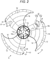
- Fig. 2 is a plane view of the axial fan 5 according to the embodiment, when viewed in a positive pressure surface side.
- Fig. 3 is a perspective view of the axial fan 5 according to the embodiment.
- the axial fan 5 includes a hub 11 having a substantially cylindrical shape and a plurality of blades 12 arranged in a circumferential direction of the hub 11.
- the axial fan 5 is made of a molding material, e.g., a resin material, and is formed as a single piece.
- the hub 11 is formed in a bicylindrical shape having an inner cylinder 11a and an outer cylinder 11b, which is disposed to face an outer circumferential surface of the inner cylinder 11a.
- the inner cylinder 11a has a shaft hole 11c into which a rotational shaft (not illustrated) of the fan motor is to be fitted.
- the outer circumferential surface of the inner cylinder 11a is formed integrally with an inner circumferential surface of the outer cylinder 11b such that a plurality of ribs 11d arranged radially is interposed between the outer circumferential surface of the inner cylinder 11a and the inner circumferential surface of the outer cylinder 11b.
- An outer circumferential surface of the outer cylinder 11b has three blades 12 formed integrally therewith and arranged at a certain distance along a circumferential direction of the outer cylinder 11b.
- Fig. 4 is a plane view of the axial fan according to the embodiment, when viewed in a negative pressure surface side.
- Fig. 5 is an enlarged plane view of the blade of the axial fan according to the embodiment, when viewed in the negative pressure surface side.
- each of the blades 12 is formed in a plate shape.
- the blade 12 is formed to have an inner circumferential edge 13, which is connected to the outer cylinder 11b of the hub 11, and an outer circumferential edge 14, which is on a line extended in a radial direction of the hub 11.
- the outer circumferential edge 14 is wider than the inner circumferential edge 13.
- the blade 12 has a front edge part 16, which is located in a front side in a rotational direction of the blade 12.
- the front edge part 16 is formed to be curved toward a rear edge part 17, which is located in an opposite side to the front edge part 16.
- the front edge part 16 is curved when viewed in a rotational axis direction X.
- a surface (blade surface) of the blade 12 is formed such that a line extending from the front edge part 16 to the rear edge part 17 along the circumferential direction of the hub 11 is gently curved from a negative pressure side of the axial fan 5 to a positive pressure side of the axial fan 5.
- a blade surface of each blade 12 on the negative pressure side is referred to as a "negative pressure surface 12a”
- a blade surface of each blade 12 on the positive pressure side is referred to as a "positive pressure surface 12b”.
- the rear edge part 17 of each blade 12 has a cutout 18 by which the rear edge part 17 is divided into an outer rear edge part 17A and an inner rear edge part 17B.
- the cutout 18 is formed so as to extend from the rear edge part 17 of the blade 12 toward the front edge part 16 of the blade 12.
- the cutout 18 has a substantial V-shape that is tapered toward the front edge part 16 when viewed in the rotational axis direction X.
- the inner rear edge part 17B has a protrusion 19 that protrudes toward the cutout 18 and is shaped in a substantial triangle.
- the protrusion 19 has a continuous surface extending along the positive pressure surface 12b of the blade 12.
- a surface of the protrusion 19 of the inner rear edge part 17B extends along the positive pressure surface 12b continuously. This reduces a flow rate of the centrifugal element of the air that flows toward the negative pressure surface 12a through the cutout 18.
- the centrifugal element of the air is effectively used, and thus an amount of air generated by the axial fan 5 is increased.
- a wind speed in the inner rear edge part 17B tends to be lower than a wind speed in the outer rear edge part 17A.
- an effect of a centrifugal force caused by the rotation of the blade 12 is more likely to occur.
- Due to the effect of the centrifugal force an airflow direction in the outer rear edge part 17A and an airflow direction in the inner rear edge part 17B become different from each other.
- the airflow direction in the inner rear edge part 17B is inclined toward the outer circumference more, as compared to the airflow direction in the outer rear edge part 17A.
- the outer rear edge part 17A has a part which is adjacent to the cutout 18 and in which a first groove part 21 including a plurality of grooves is provided along the outer rear edge part 17A.
- the plurality of grooves of the first groove part 21 penetrates through the blade 12 in a thickness direction of the blade 12, and extends toward the front edge part 16.
- the inner rear edge part 17B has a part which is adjacent to the cutout 18 and in which a second groove part 22 including a plurality of grooves is provided along the inner rear edge part 17B.
- the plurality of grooves of the second groove part 22 penetrates through the blade 12 in the thickness direction of the blade 12, and extends toward the front edge part 16.
- the second groove part 22 is disposed in the protrusion 19, which is included in the inner rear edge part 17B.
- the second groove part 22 is disposed along an outer edge of the protrusion 19, which is located in an opened part of the substantially V-shaped cutout 18.
- the first groove part 21 and the second groove part 22 have different shapes when viewed in the rotational axis direction X of the hub 11. Note that there are differences between the first groove part 21 and the second groove part 22 other than the shape viewed in the rotational axis direction X.
- the first groove part 21 and the second groove part 22 have different shapes when viewed in the positive pressure surface 12b, too.
- the first groove part 21 and the second groove part 22 have respective shapes having different depths, different pitches, and/or the like according to the wind speeds in the respective positions where they are provided (the outer rear edge part 17A and the inner rear edge part 17B). This makes it possible to appropriately suppress or reduce a noise caused by the flow of the air.
- An angle of the second groove part 22 made by a direction (depth direction) of the second groove part 22, the direction extending from the rear edge part 17 toward the front edge part 16, and the radial direction of the hub 11 of the second groove part 22 is smaller than an angle of the first groove part 21 made by the depth direction of the first groove part 21 and the radial direction of the hub 11 of the first groove part 21.
- These angles are set based on the airflow direction in the outer rear edge part 17A and the airflow direction in the inner rear edge part 17B. Namely, the first groove part 21 extends along the airflow direction in the outer rear edge part 17A. Similarly, the second groove part 22 extends along the airflow direction in the inner rear edge part 17B.
- the first groove part 21 and the second groove part 22 are formed in suitable shapes according to the airflow directions in respective positions of the rear edge part 17 where the first groove part 21 and the second groove part 22 are provided.
- the first groove part 21 and the second groove part 22 finely divide a vortex occurring in the rear edge part 17 in an effective manner. This enhances the effect of reducing a noise caused by the flow of the air.
- each of the first thickness-reduced part 31 and the second thickness-reduced part 32 is a recess that is formed in a part of the negative pressure surface 12a of the blade 12 and has a predetermined shape, and is a cored-out part formed in the thickness direction of the blade 12.
- the negative pressure surface 12a of the blade 12 has a first rib 30a and a second rib 30b each extending from the hub 11 toward an outer circumference of the blade 12 along the front edge part 16.
- the negative pressure surface 12a has the first thickness-reduced part 31 adjacent to ends of the first rib 30a and the second rib 30b, the ends are closer to the outer circumference.
- the first thickness-reduced part 31 is formed on the negative pressure surface 12a so as to be shaped in a substantial triangle.
- the first thickness-reduced part 31 has two side surfaces 31a and 31b arranged such that a distance between the side surfaces 31a and 31b becomes larger as parts of the side surfaces 31a and 31b where the distance is measured are closer to the outer circumferential edge 14 of the blade 12.
- the first rib 30a and the second rib 30b extend so as to be substantially parallel to each other along a first tangent line L1 from the inner circumferential edge 13 of the blade 12 toward the outer circumferential edge 14 of the blade 12.
- the first tangent line L1 is a straight line that extends through a rotational center O of the hub 11 and is in contact with, at a first tangent point S1, an outer edge of the front edge part 16, which is curved.
- the first rib 30a and the second rib 30b have respective ends connected to the outer circumferential surface of the outer cylinder 11b of the hub 11.
- the first rib 30a and the second rib 30b are connected via a connecting member 30c, which extends in the circumferential direction of the hub 11.
- the first rib 30a, the second rib 30b, and the connecting member 30c make the blade 12 partially thicker, and thus have a function of reinforcing the inner circumferential edge 13 of the blade 12.
- the first rib 30a and the second rib 30b respectively have recesses surrounding the first rib 30a and the second rib 30b, and these recesses also serve as the thickness-reduced parts. Note that, in a molding die at the time of molding of the axial fan 5, a molding material flows from a part of the die corresponding to the inner circumferential edge 13 of the blade 12 toward a part of the die corresponding to the outer circumferential edge 14.
- the molding material flows through parts of the die corresponding to the first rib 30a and the second rib 30b at a higher speed than those in other parts of the die, since the first rib 30a and the second rib 30b are thick.
- the embodiment includes the two first rib 30a and second rib 30b.
- the number of ribs is not limited to this. Depending on a condition for the molding, one rib or three or more ribs may be provided.
- the negative pressure surface 12a of the blade 12 has the second thickness-reduced part 32.
- the second thickness-increased part 34 has a flow-speed increasing part 34a.
- the flow-speed increasing part 34a has a predetermined width W2.
- the second thickness-reduced part 32 is shaped in a substantial trapezoid, and has side surfaces 32a and 32b.
- a distance W1 between the side surface 32a and the side surface 32b is reduced as parts of the side surface 32a and the side surface 32b where the distance W1 is measured are located closer to the outer circumferential edge 14 than the inner circumferential edge 13.
- the second thickness-reduced part 32 is positioned so as to be adjacent to the outer circumferential surface of the outer cylinder 11b of the hub 11 and to overlap a second tangent line L2 (described later).
- the second thickness-increased part 34 is thicker than the second thickness-reduced part 32, which is adjacent thereto.
- a part of the die corresponding to the second thickness-increased part 34 is a portion where a flow resistance of the molding material during the molding is low and the molding material is easy to flow.
- the second thickness-increased part 34 is configured to have a small width. This allows the molding material to flow at a higher speed during the molding. Since the molding material flows at a higher speed, the molding material that has passed through the part of the die corresponding to the second thickness-increased part 34 easily spreads to parts of the die corresponding to the cutout 18, the protrusion 19, and the second groove part 22.
- the predetermined width W2 of the flow-speed increasing part 34a is set so as to allow the molding material that has passed through the part of the die corresponding to the second thickness-increased part 34 to achieve a flow speed with which the molding material easily spreads to the parts of the die corresponding to the cutout 18, the protrusion 19, and the second groove part 22.
- the following state occurs in the blade 12 due to the flow-speed increasing part 34a (the part having the width W2). That is, inside the molding die, a speed of the molding material flowing from the part of the die corresponding to the inner circumferential edge 13 toward a part of the die corresponding to the inner rear edge part 17B is higher than a speed of the molding material flowing through a part of the die corresponding to the second thickness-reduced part 32, which is adjacent to the inner rear edge part 17B. Thanks to the small width W2 of the flow-speed increasing part 34a, the flow speed of the molding material during the molding of the axial fan 5 is increased.
- the width W2 is set according to an external shape of the rear edge part 17 of the blade 12.
- the width W2 is set depending on a molding condition determined according to the shapes of the second groove part 22 of the inner rear edge part 17B and the protrusion 19.
- a distance between the side surface 32b of the second thickness-reduced part 32 and the inner rear edge part 17B is minimum at the width W2 in the flow-speed increasing part 34a, and the distance increases as it gets closer to the outer circumferential edge 14 than the inner circumferential edge 13. This properly determines flow of the molding material during the molding, thereby allowing the molding material to spread to the parts of the die corresponding to the cutout 18, the protrusion 19, and the second groove part 22.
- the negative pressure surface 12a of the blade 12 has a first thickness-increased part 33 positioned so as to be closer to the front edge part 16 than the second tangent line L2 is and to extend from the inner circumferential edge 13 of the blade 12 toward the outer circumferential edge 14 of the blade 12.
- the second tangent line L2 is a straight line that extends in the radial direction of the hub 11 so as to extend through the rotational center O of the hub 11 and be in contact with a valley part 18a at a second tangent point S2.
- the valley part 18a is a part of an outer edge of the cutout 18, the part being closer to the front edge part 16 than any other parts of the cutout 18.
- the first thickness-increased part 33 is interposed between the first thickness-reduced part 31 and the second thickness-reduced part 32 on the negative pressure surface 12a.
- the second thickness-reduced part 32 is formed so as to be close to the inner rear edge part 17B.
- the first thickness-reduced part 31 and the second thickness-reduced part 32 respectively have the side surfaces 31a and 32a, which are substantially parallel to each other.
- the first thickness-increased part 33 is formed in a substantial belt-shape extending from the hub 11 toward the outer circumferential edge 14.
- the first thickness-increased part 33 has an end that is closer to the inner circumferential edge 13.
- the end of the first thickness-increased part 33 is partially connected to the outer circumferential surface of the outer cylinder 11b of the hub 11, and is partially adjacent to a region including the first rib 30a and the second rib 30b.
- the first thickness-increased part 33 is a region which is included in the negative pressure surface 12a of the blade 12 and which does not have a thickness-reduced part or a recess.
- the first thickness-increased part 33 is thicker than the first thickness-reduced part 31 and the second thickness-reduced part 32, which are adjacent to the first thickness-increased part 33.
- a flow resistance of the molding material during the molding of the axial fan 5 is low in a part of the die corresponding to the first thickness-increased part 33. Therefore, the part of the die corresponding to the first thickness-increased part 33 is a portion through which the molding material is easy to flow.
- each of the dimples 36 is a recess having a cross-section of an arc-shape.
- the dimples 36 are arranged at a predetermined distance in the radial direction and the circumferential direction of the hub 11. When the blade 12 is rotated, the dimples 36 cause a secondary flow of the air inside the dimples 36. With this, the dimples 36 suppress or reduce development of a boundary layer of the airflow, and accordingly suppress or reduce a noise occurring due to a pressure fluctuation caused by separation of the boundary layer.
- the dimples 36 have a function of suppressing or reducing occurrence of a noise by suppressing or reducing occurrence of the boundary layer separation on the negative pressure surface 12a, and a function as the thickness-reduced part similar to those of the first and second thickness-reduced parts 31 and 32.
- the side surface 31a of the first thickness-reduced part 31, which is located closer to the front edge part 16, and the side surface 32a of the second thickness-reduced part 32, which is located closer to the rear edge part 17, are formed so as to be substantially parallel to each other when viewed in a direction orthogonal to the negative pressure surface 12a.
- the shape of the first thickness-increased part 33 is not limited to this.
- the first thickness-increased part 33 may have a shape whose distance between the side surface 31a of the first thickness-reduced part 31 and the side surface 32a of the second thickness-reduced part 32 is increased as parts of the side surface 31a and the side surface 32a where the distance is measured are located closer to the outer circumferential edge 14 or reduced as these parts are located closer to the outer circumferential edge 14.
- the shape of the first thickness-increased part 33 is set, for example, depending on a condition for flowing the molding material from the part of the die corresponding to the inner circumferential edge 13 of the blade 12 toward the part of the die corresponding to the outer circumferential edge 14 of the blade 12, where the condition is set according to the external shape of the blade 12.
- the molding die (not illustrated) for the above-described axial fan 5 has a gate 28 located in a position corresponding to an end surface of the outer cylinder 11b of the hub 11 (see Fig. 5 ).
- the gate 28 is used to inject a molten molding material therethrough into a cavity for molding the axial fan 5.
- the gate 28 is disposed in the rotational axis direction X (see Fig. 3 ) toward the hub 11.
- the axial fan 5 is formed by (i) injecting the molding material into the molding die through the gate 28 such that the molding material flows from the part of the die corresponding to the inner circumferential edge 13 of the blade 12 toward the part of the die corresponding to the outer circumferential edge 14 of the blade 12 through a part of the die corresponding to the hub 11 and (ii) filling the cavity with the molding material.
- the molding material flows along the parts of the die corresponding to the first rib 30a and the second rib 30b, which serve as flow passages in the molding die, such that the molding material flows from a part of the die corresponding to a part of the inner circumferential edge 13 being closer to the front edge part 16 toward the part of the die corresponding to the outer circumferential edge 14. Thanks to a part of the die corresponding to the first thickness-reduced part 31, in which the flow resistance in the molding die becomes higher, the molding material that has flowed along the parts of the die corresponding to the first rib 30a and the second rib 30b is properly dispersed to a portion having a relatively low flow resistance.
- the molding material that has passed through the parts of the die corresponding to the first rib 30a and the second rib 30b flows through a part of the die corresponding to the front edge part 16, which is shaped in an arc, and then appropriately flows into the part of the die corresponding to the outer circumferential edge 14, which extends forward.
- the first thickness-reduced part 31 is adjacent to the ends of the first rib 30a and the second rib 30b, the ends being closer to the outer circumference.
- the molding material is properly dispersed to the portion having a relatively lower flow resistance compared to the part of the die corresponding to the first thickness-reduced part 31. This properly adjusts a balance in the flow of the molding material in the part of the die corresponding to the front edge part 16.
- the molding material flows through a part of the die corresponding to the part having the width W2 (flow-speed increasing part 34a), which is adjacent to the second thickness-reduced part 32, such that the molding material flows from a part of the die corresponding to a part of the inner circumferential edge 13 being closer to the inner rear edge part 17B toward the part of the die corresponding to the outer circumferential edge 14.
- the molding material flows through the part of the die corresponding to the part having the width W2, which is narrowed by the second thickness-reduced part 32 adjacent thereto. This increases a flow speed of the molding material, thereby facilitating the flow of the molding material into a part of the die corresponding to an outer edge of the inner rear edge part 17B.
- the molding material flows properly especially into parts of the die corresponding to the cutout 18, the protrusion 19, and the second groove part 22.
- the second thickness-reduced part 32 which has the predetermined distance W1 is positioned in the blade 12. This properly adjusts the manner in which the molding material flows in a roundabout manner to a part of the die corresponding to the cutout 18 of the inner rear edge part 17B and the vicinity of the cutout 18.
- the molding material flows along the part of the die corresponding to the first thickness-increased part 33 such that the molding material flows from the part of the die corresponding to the inner circumferential edge 13 toward the part of the die corresponding to the outer circumferential edge 14.
- the first thickness-increased part 33 is positioned so as to be closer to the front edge part 16 than the second tangent line L2 is.
- the molding material properly flows into a part of the die corresponding to the outer rear edge part 17A, while avoiding the part of the die corresponding to the cutout 18, which is a projection that hinders the flow.
- the first thickness-increased part 33 is formed between the side surfaces 31a and 32a, which are substantially parallel to each other.
- the above-described second thickness-reduced part 32 is formed in a position that does not hinder the flow of the molding material from the part of the die corresponding to the hub 11 toward the part of the die corresponding to the outer rear edge part 17A. Due to the side surface 32a included in the second thickness-reduced part 32, the second thickness-reduced part 32 also has a function of adjusting the flow of the molding material passing through the part of the die corresponding to the first thickness-increased part 33. In addition, the first thickness-increased part 33 has the end that is closer to the inner circumferential edge 13 and is adjacent to the first rib 30a and the second rib 30b.
- a relatively large amount of molding material flows into the parts of the die corresponding to the first rib 30a and the second rib 30b.
- the molding material flowing through the parts of the die corresponding to the first rib 30a and the second rib 30b smoothly flows into the part of the die corresponding to the first thickness-increased part 33. Consequently, a flow rate of the molding material flowing into the part of the die corresponding to the outer rear edge part 17A through the part of the die corresponding to the first thickness-increased part 33 is regulated appropriately.
- the negative pressure surface 12a of each blade 12 of the axial fan 5 has the first rib 30a and the second rib 30b, which extend from the hub 11 toward an outer circumference of the front edge part 16.
- the first thickness-reduced part 31 is formed so as to be adjacent to the ends of the first rib 30a and the second rib 30b, the ends being closer to the outer circumference. Consequently, during molding of the axial fan 5, the flow of the molding material passing through the parts of the die corresponding to the first rib 30a and the second rib 30b is regulated appropriately. Thus, it is possible to accurately form the external shape of the front edge part 16. Therefore, thanks to the first thickness-reduced part 31, the embodiment is able to reduce a weight of the blade 12 and to enhance moldability of the blade 12.
- the negative pressure surface 12a of each blade 12 of the axial fan 5 has the second thickness-reduced part 32.
- the second thickness-reduced part 32 extends from the hub 11 toward the outer circumferential edge 14 while retaining the predetermined distance W2 from the inner rear edge part 17B. Consequently, during molding of the axial fan 5, the molding material flows through the part of the die corresponding to the part having the width W2 (flow-speed increasing part 34a), which is narrowed by the second thickness-reduced part 32 adjacent thereto. This facilitates the flow of the molding material into the part of the die corresponding to the inner rear edge part 17B.
- the molding material flows properly especially into the parts of the die corresponding to the cutout 18, the protrusion 19, and the second groove part 22. Consequently, it is possible to accurately form the external shape of the inner rear edge part 17B. Therefore, thanks to the second thickness-reduced part 32, the embodiment is able to reduce a weight of the blade 12 and to enhance moldability of the blade 12 having the cutout 18.
- the negative pressure surface 12a of each blade 12 of the axial fan 5 has the first thickness-increased part 33.
- the first thickness-increased part 33 is interposed between the first thickness-reduced part 31 and the second thickness-reduced part 32, and is positioned so as to be closer to the front edge part 16 than the second tangent line L2 is.
- the first thickness-reduced part 31 and the second thickness-reduced part 32 are formed on both sides of the first thickness-increased part 33. Namely, the first thickness-reduced part 31 is formed so as to be adjacent to a part of the first thickness-increased part 33, the part being closer to the front edge part 16.
- the second thickness-reduced part 32 is formed so as to be adjacent to a part of the first thickness-increased part 33, the part being closer to the rear edge part 17. Consequently, during molding of the axial fan 5, the molding material flows as follows. That is, while avoiding the part of the die corresponding to the cutout 18, which hinders the flow in the molding die, the molding material appropriately flows into the part of the die corresponding to the outer rear edge part 17A through a part of the die corresponding to a part of the first thickness-increased part 33 being closer to the front edge part 16 than the second tangent line L2 is. Thus, it is possible to accurately form the external shape of the inner rear edge part 17B. Therefore, thanks to the first thickness-increased part 33, the embodiment is able to reduce a weight of the blade 12 and to enhance moldability of the blade 12 having the cutout 18.
- the first thickness-reduced part 31 and the second thickness-reduced part 32 of the axial fan 5 respectively have the side surfaces 31a and 32a, which are substantially parallel to each other. Thanks to this, the flow direction of the molding material passing through the part of the die corresponding to the first thickness-increased part 33 is regulated properly. Thus, the molding material properly flows to the part of the die corresponding to the outer rear edge part 17A in a roundabout manner through the part of the die corresponding to the part closer to the front edge part 16 than the cutout 18. This makes it possible to more accurately form the external shape of the inner rear edge part 17B. Therefore, thanks to the side surfaces 31a and 32a, the embodiment is able to reduce a weight of the blade 12 and to further enhance moldability of the blade 12.
- the embodiment includes the first thickness-reduced part 31, which is adjacent to the first rib 30a and the second rib 30b, the second thickness-reduced part 32, which has the distance W2 from the inner rear edge part 17B, and the first thickness-increased part 33, which is interposed between the first thickness-reduced part 31 and the second thickness-reduced part 32.
- the configuration of the axial fan according to the embodiment is not limited to this. It is only necessary for the axial fan of the embodiment to include at least one of the first thickness-reduced part 31, the second thickness-reduced part 32, and the first thickness-increased part 33 described above. This brings about an effect of appropriately regulating the flow of the molding material so as to enhance moldability of the blade 12.
- both of the first thickness-reduced part 31 and the second thickness-reduced part 32 are provided on the negative pressure surface 12a.
- both of the first thickness-reduced part 31 and the second thickness-reduced part 32 may be provided on the positive pressure surface 12b.
- the first thickness-reduced part 31 and the second thickness-reduced part 32 may be provided separately such that the first thickness-reduced part 31 is provided on the negative pressure surface 12a and the second thickness-reduced part 32 is provided on the positive pressure surface 12b, or vice versa.
- An air conditioner according to an embodiment of the present disclosure may be any one of first to sixth axial fans below or a first outdoor unit below.
- the first axial fan includes: a hub; and a plurality of blades arranged in a circumferential direction of the hub, wherein each of the plurality of blades has a cutout in a rear edge part of the blade, the rear edge part being opposite to a front edge part of the blade in a rotational direction of the blade, the cutout extending from the rear edge part toward the front edge part such that the cutout divides the rear edge part into an outer rear edge part and an inner rear edge part, wherein the blade has a blade surface having a rib extending from the hub toward an outer circumference along the front edge part, and wherein a first thickness-reduced part, in which the blade is thinned, is formed so as to be adjacent to an end of the rib, the end being closer to the outer circumference.
- the second axial fan is the first axial fan configured such that: the inner rear edge part has a part which is adjacent to the cutout and in which a plurality of grooves is provided along the inner rear edge part, the plurality of grooves penetrating through the blade in a thickness direction of the blade, the plurality of grooves extending toward the front edge part; and the blade surface of the blade has a second thickness-reduced part, in which the blade is thinned, the second thickness-reduced part being extending from the hub toward the outer circumference of the blade while retaining a predetermined distance from the inner rear edge part.
- the third axial fan is the second axial fan configured such that the blade surface of the blade has a thickness-increased part being located between the first thickness-reduced part and the second thickness-reduced part such that the thickness-increased part is closer to the front edge part relative to a tangent line extending through a rotational center of the hub and being in contact with a valley part of the cutout, the valley part being closer to the front edge part than any other parts of the cutout, the thickness-increased part extending from an inner circumference of the blade toward the outer circumference of the blade.
- the fourth axial fan includes: a hub; and a plurality of blades arranged in a circumferential direction of the hub, wherein each of the plurality of blades has a cutout in a rear edge part of the blade, the rear edge part being opposite to a front edge part of the blade in a rotational direction of the blade, the cutout extending from the rear edge part toward the front edge part such that the cutout divides the rear edge part into an outer rear edge part and an inner rear edge part, wherein the blade has a blade surface having a thickness-increased part being located closer to the front edge part relative to a tangent line extending through a rotational center of the hub and being in contact with a valley part of the cutout, the valley part being closer to the front edge part than any other parts of the cutout, the thickness-increased part extending from an inner circumference of the blade toward an outer circumference of the blade, wherein a first thickness-reduced part and a second thickness-reduced part, in each of which the blade is
- the fifth axial fan is the fourth axial fan configured such that: a plurality of grooves is provided in a part of the inner rear edge part, the part being adjacent to the cutout, the plurality of grooves being arranged along the inner rear edge part, the plurality of grooves penetrating the blade in a thickness direction of the blade, the plurality of grooves extending toward the front edge part; and the second thickness-reduced part is formed to extend from the hub toward the outer circumference of the blade while retaining a predetermined distance from the inner rear edge part.
- the sixth axial fan includes: a hub; and a plurality of blades arranged in a circumferential direction of the hub, wherein each of the plurality of blades has a cutout in a rear edge part of the blade, the rear edge part being opposite to a front edge part of the blade in a rotational direction of the blade, the cutout extending from the rear edge part toward the front edge part such that the cutout divides the rear edge part into an outer rear edge part and an inner rear edge part, wherein the inner rear edge part has a part which is adjacent to the cutout and in which a plurality of grooves is provided along the inner rear edge part, the plurality of grooves penetrating through the blade in a thickness direction of the blade, the plurality of grooves extending toward the front edge part, and wherein the blade surface of the blade has a thickness-reduced part, in which the blade is thinned, the thickness-reduced part extending from the hub toward an outer circumference of the blade while retaining a predetermined distance from the inner
- the first outdoor unit includes: a compressor for compressing a refrigerant; a heat exchanger which is connected to the compressor and through which the refrigerant flows; and any of the first to sixth axial fans for sending air to the heat exchanger.
Landscapes
- Engineering & Computer Science (AREA)
- Mechanical Engineering (AREA)
- General Engineering & Computer Science (AREA)
- Chemical & Material Sciences (AREA)
- Combustion & Propulsion (AREA)
- Structures Of Non-Positive Displacement Pumps (AREA)
Claims (5)
- Axiallüfterrad, umfassend:- eine Nabe (11),- mehrere Flügel (12), die in einer Umfangsrichtung der Nabe angeordnet sind,- eine Aussparung (18) in einem Hinterkantenabschnitt eines jeden der mehreren Flügel, wobei der Hinterkantenabschnitt einem Vorderkantenabschnitt (16) eines jeden der mehreren Flügel in einer Drehrichtung eines jeden der mehreren Flügel gegenüberliegt, wobei sich die Aussparung von dem Hinterkantenabschnitt zu dem Vorderkantenabschnitt (16) erstreckt, dergestalt, dass die Aussparung den Hinterkantenabschnitt in einen äußeren Hinterkantenabschnitt (17A) und einen inneren Hinterkantenabschnitt (17B) unterteilt,- einen ersten Abschnitt mit erhöhter Dicke (33) in einer Flügeloberfläche eines jeden der mehreren Flügel, wobei der erste Abschnitt mit erhöhter Dicke (33) näher an dem Vorderkantenabschnitt (16) liegt als eine Tangentenlinie (L2), wobei sich die Tangentenlinie (L2) durch einen Drehmittelpunkt (O) der Nabe (11) erstreckt und in Kontakt mit einem Vertiefungsabschnitt (18a) der Aussparung (18) ist, wobei der Vertiefungsabschnitt näher an dem Vorderkantenabschnitt (16) liegt als alle anderen Teile der Aussparung, wobei sich der erste Abschnitt mit erhöhter Dicke (33) von einem inneren Umfang eines jeden der mehreren Flügel zu einem äußeren Umfang eines jeden der mehreren Flügel erstreckt,- einen ersten Abschnitt mit verringerter Dicke (31), der benachbart zu einem Abschnitt des ersten Abschnitts mit erhöhter Dicke (33) ist, wobei der Abschnitt näher an dem Vorderkantenabschnitt (16) liegt, wobei jeder der mehreren Flügel in dem ersten Abschnitt mit verringerter Dicke (31) verdünnt ist, und- einen zweiten Abschnitt mit verringerter Dicke (32), der dergestalt angeordnet ist, dass er die Tangentenlinie (L2) überlappt und benachbart zu einem Abschnitt des ersten Abschnitts mit erhöhter Dicke (33) ist, wobei der Abschnitt näher an dem Hinterkantenabschnitt (17) liegt, wobei jeder der mehreren Flügel in dem zweiten Abschnitt mit verringerter Dicke (32) verdünnt ist.
- Axiallüfterrad nach Anspruch 1, ferner umfassend:mehrere Nuten in einem Abschnitt des inneren Hinterkantenabschnitts (17B), wobei der Abschnitt des inneren Hinterkantenabschnitts benachbart zu der Aussparung (18) ist, wobei die mehreren Nuten entlang des inneren Hinterkantenabschnitts angeordnet sind, jeden der mehreren Flügel in einer Dickenrichtung eines jeden der mehreren Flügel durchdringen und sich zu dem Vorderkantenabschnitt hin erstrecken,wobei sich der zweite Abschnitt mit verringerter Dicke (32) unter Beibehaltung eines vorgegebenen Abstands (W2) zu dem inneren Hinterkantenabschnitt (17B) von der Nabe zu dem äußeren Umfang eines jeden der mehreren Flügel erstreckt.
- Axiallüfterrad nach Anspruch 2, ferner umfassend:
einen zweiten Abschnitt mit erhöhter Dicke (34), der zwischen dem zweiten Abschnitt mit verringerter Dicke (32) und dem inneren Hinterkantenabschnitt (17B) angeordnet ist. - Axiallüfterrad nach einem der vorhergehenden Ansprüche, wobei der erste Abschnitt mit erhöhter Dicke (33) zwischen dem ersten Abschnitt mit verringerter Dicke (31) und dem zweiten Abschnitt mit verringerter Dicke (32) angeordnet ist.
- Außeneinheit (1), umfassend:- einen Verdichter (3), der ein Kühlmittel verdichtet,- einen Wärmetauscher (4), der mit dem Verdichter verbunden ist und durch den das Kühlmittel fließt, und- ein Axiallüfterrad (5) nach einem der Ansprüche 1 bis 4, das Luft zu dem Wärmetauscher befördert.
Applications Claiming Priority (1)
| Application Number | Priority Date | Filing Date | Title |
|---|---|---|---|
| JP2016188109A JP6926428B2 (ja) | 2016-09-27 | 2016-09-27 | 軸流ファン及びそれを用いた室外機 |
Publications (2)
| Publication Number | Publication Date |
|---|---|
| EP3299632A1 EP3299632A1 (de) | 2018-03-28 |
| EP3299632B1 true EP3299632B1 (de) | 2021-12-22 |
Family
ID=59061919
Family Applications (1)
| Application Number | Title | Priority Date | Filing Date |
|---|---|---|---|
| EP17176027.5A Active EP3299632B1 (de) | 2016-09-27 | 2017-06-14 | Axiallüfter und ausseneinheit damit |
Country Status (5)
| Country | Link |
|---|---|
| US (1) | US10578320B2 (de) |
| EP (1) | EP3299632B1 (de) |
| JP (1) | JP6926428B2 (de) |
| CN (1) | CN107869483B (de) |
| AU (1) | AU2017203413B2 (de) |
Families Citing this family (23)
| Publication number | Priority date | Publication date | Assignee | Title |
|---|---|---|---|---|
| US10400783B1 (en) * | 2015-07-01 | 2019-09-03 | Dometic Sweden Ab | Compact fan for a recreational vehicle |
| KR102479815B1 (ko) * | 2015-11-30 | 2022-12-23 | 삼성전자주식회사 | 송풍팬 및 이를 구비하는 공기 조화기 |
| ES2767806T3 (es) * | 2016-07-01 | 2020-06-18 | Mitsubishi Electric Corp | Ventilador de hélice |
| USD870254S1 (en) * | 2017-08-09 | 2019-12-17 | Mitsubishi Electric Corporation | Propeller fan |
| WO2019030868A1 (ja) * | 2017-08-09 | 2019-02-14 | 三菱電機株式会社 | プロペラファン、送風装置及び冷凍サイクル装置 |
| CN110945250B (zh) * | 2017-08-09 | 2021-09-28 | 三菱电机株式会社 | 螺旋桨风扇、送风装置及制冷循环装置 |
| JP1600724S (de) * | 2017-08-09 | 2018-04-02 | ||
| JP1600722S (de) * | 2017-08-09 | 2018-04-02 | ||
| WO2020028010A1 (en) | 2018-08-02 | 2020-02-06 | Horton, Inc. | Low solidity vehicle cooling fan |
| WO2020103400A1 (zh) * | 2018-11-22 | 2020-05-28 | 广东美的制冷设备有限公司 | 轴流风轮及具有其的空调器 |
| EP3889440B1 (de) * | 2018-11-30 | 2023-08-23 | Fujitsu General Limited | Propellerlüfter |
| JP7088307B2 (ja) | 2018-11-30 | 2022-06-21 | 株式会社富士通ゼネラル | プロペラファン |
| CN113167291B (zh) * | 2018-11-30 | 2023-05-09 | 富士通将军股份有限公司 | 螺旋桨式风扇 |
| EP3992468B1 (de) * | 2019-06-25 | 2024-07-10 | Mitsubishi Electric Corporation | Axiallüfter, gebläsevorrichtung und kältekreislaufvorrichtung |
| JP7014972B2 (ja) * | 2019-08-09 | 2022-02-02 | ダイキン工業株式会社 | 軸流ファン及び冷凍サイクル装置 |
| CN211259119U (zh) * | 2019-12-27 | 2020-08-14 | 依必安派特风机(上海)有限公司 | 轴流叶轮 |
| CN112049819A (zh) * | 2020-08-31 | 2020-12-08 | 青岛海尔空调电子有限公司 | 风轮、风扇及空调器室外机 |
| JP7093042B1 (ja) | 2021-01-21 | 2022-06-29 | ダイキン工業株式会社 | プロペラファン、及び空気調和機 |
| CN114876828B (zh) * | 2021-02-05 | 2024-09-03 | 全亿大科技(佛山)有限公司 | 风扇 |
| CN115126708A (zh) * | 2021-03-26 | 2022-09-30 | 全亿大科技(佛山)有限公司 | 叶轮及散热风扇 |
| CN115717605B (zh) * | 2021-08-24 | 2026-01-23 | 宁波奥克斯电气有限公司 | 一种轴流风轮以及空调器 |
| TWI774623B (zh) * | 2021-12-14 | 2022-08-11 | 技嘉科技股份有限公司 | 風扇裝置 |
| JP7393682B2 (ja) * | 2022-03-31 | 2023-12-07 | ダイキン工業株式会社 | 軸流ファン |
Family Cites Families (8)
| Publication number | Priority date | Publication date | Assignee | Title |
|---|---|---|---|---|
| JP2613272B2 (ja) * | 1988-08-29 | 1997-05-21 | 株式会社日立製作所 | 軸流ファン |
| JP3448136B2 (ja) | 1994-11-08 | 2003-09-16 | 三菱重工業株式会社 | プロペラファン |
| JP3365374B2 (ja) * | 1999-10-20 | 2003-01-08 | ダイキン工業株式会社 | 軸流ファン用羽根車 |
| JP2011074817A (ja) * | 2009-09-30 | 2011-04-14 | Sanyo Electric Co Ltd | 軸流ファン |
| JP5353994B2 (ja) * | 2011-11-21 | 2013-11-27 | ダイキン工業株式会社 | 軸流ファン |
| CN102588339B (zh) * | 2012-03-01 | 2016-02-03 | Tcl空调器(中山)有限公司 | 风扇结构及轴流风扇 |
| JP6097127B2 (ja) * | 2013-04-10 | 2017-03-15 | ジョンソンコントロールズ ヒタチ エア コンディショニング テクノロジー(ホンコン)リミテッド | 空気調和装置 |
| CN104061187A (zh) * | 2014-06-30 | 2014-09-24 | 珠海格力电器股份有限公司 | 一种轴流风叶、轴流风机及空调机 |
-
2016
- 2016-09-27 JP JP2016188109A patent/JP6926428B2/ja active Active
-
2017
- 2017-05-22 AU AU2017203413A patent/AU2017203413B2/en active Active
- 2017-05-30 US US15/607,828 patent/US10578320B2/en active Active
- 2017-06-12 CN CN201710436950.2A patent/CN107869483B/zh active Active
- 2017-06-14 EP EP17176027.5A patent/EP3299632B1/de active Active
Also Published As
| Publication number | Publication date |
|---|---|
| AU2017203413B2 (en) | 2023-07-27 |
| US20180087784A1 (en) | 2018-03-29 |
| JP2018053749A (ja) | 2018-04-05 |
| CN107869483B (zh) | 2021-06-11 |
| CN107869483A (zh) | 2018-04-03 |
| AU2017203413A1 (en) | 2018-04-12 |
| EP3299632A1 (de) | 2018-03-28 |
| JP6926428B2 (ja) | 2021-08-25 |
| US10578320B2 (en) | 2020-03-03 |
Similar Documents
| Publication | Publication Date | Title |
|---|---|---|
| EP3299632B1 (de) | Axiallüfter und ausseneinheit damit | |
| EP3290715B1 (de) | Axiallüfter und ausseneinheit | |
| EP2264321B1 (de) | Propellerlüfter aus kunststoff | |
| US9556881B2 (en) | Propeller fan | |
| EP2902639B1 (de) | Propellerlüfter und klimaanlage damit | |
| US9404511B2 (en) | Free-tipped axial fan assembly with a thicker blade tip | |
| US8926286B2 (en) | Propeller fan, molding die, and fluid feeder | |
| KR101981922B1 (ko) | 프리-팁형 축류 팬 조립체 | |
| JP6583770B2 (ja) | 遠心式送風機 | |
| JP6066691B2 (ja) | プロペラファン及び前記プロペラファンを用いた空気調和装置 | |
| KR20140039976A (ko) | 프로펠러 팬 및 이 프로펠러 팬을 사용한 공기조화장치 | |
| EP2149713B1 (de) | Axialstromventilator | |
| JP6971960B2 (ja) | プロペラファン | |
| JP6794725B2 (ja) | 軸流ファン及び室外機 | |
| JP6876146B2 (ja) | 遠心圧縮機及びこの遠心圧縮機を備えたターボチャージャ | |
| CN110873073B (zh) | 散热风扇 | |
| JP6776739B2 (ja) | 軸流ファン及び室外機 | |
| WO2020110969A1 (ja) | プロペラファン | |
| JP6084368B2 (ja) | プロペラファンおよびこれを備えた流体送り装置、扇風機ならびにプロペラファンの成形用金型 | |
| US20240084813A1 (en) | Fan | |
| JPS6165097A (ja) | 軸流フアン | |
| WO2019111973A1 (ja) | プロペラファン |
Legal Events
| Date | Code | Title | Description |
|---|---|---|---|
| PUAI | Public reference made under article 153(3) epc to a published international application that has entered the european phase |
Free format text: ORIGINAL CODE: 0009012 |
|
| STAA | Information on the status of an ep patent application or granted ep patent |
Free format text: STATUS: THE APPLICATION HAS BEEN PUBLISHED |
|
| AK | Designated contracting states |
Kind code of ref document: A1 Designated state(s): AL AT BE BG CH CY CZ DE DK EE ES FI FR GB GR HR HU IE IS IT LI LT LU LV MC MK MT NL NO PL PT RO RS SE SI SK SM TR |
|
| AX | Request for extension of the european patent |
Extension state: BA ME |
|
| STAA | Information on the status of an ep patent application or granted ep patent |
Free format text: STATUS: REQUEST FOR EXAMINATION WAS MADE |
|
| 17P | Request for examination filed |
Effective date: 20180907 |
|
| RBV | Designated contracting states (corrected) |
Designated state(s): AL AT BE BG CH CY CZ DE DK EE ES FI FR GB GR HR HU IE IS IT LI LT LU LV MC MK MT NL NO PL PT RO RS SE SI SK SM TR |
|
| GRAP | Despatch of communication of intention to grant a patent |
Free format text: ORIGINAL CODE: EPIDOSNIGR1 |
|
| STAA | Information on the status of an ep patent application or granted ep patent |
Free format text: STATUS: GRANT OF PATENT IS INTENDED |
|
| INTG | Intention to grant announced |
Effective date: 20210709 |
|
| GRAS | Grant fee paid |
Free format text: ORIGINAL CODE: EPIDOSNIGR3 |
|
| GRAA | (expected) grant |
Free format text: ORIGINAL CODE: 0009210 |
|
| STAA | Information on the status of an ep patent application or granted ep patent |
Free format text: STATUS: THE PATENT HAS BEEN GRANTED |
|
| AK | Designated contracting states |
Kind code of ref document: B1 Designated state(s): AL AT BE BG CH CY CZ DE DK EE ES FI FR GB GR HR HU IE IS IT LI LT LU LV MC MK MT NL NO PL PT RO RS SE SI SK SM TR |
|
| REG | Reference to a national code |
Ref country code: GB Ref legal event code: FG4D |
|
| REG | Reference to a national code |
Ref country code: CH Ref legal event code: EP |
|
| REG | Reference to a national code |
Ref country code: DE Ref legal event code: R096 Ref document number: 602017051162 Country of ref document: DE |
|
| REG | Reference to a national code |
Ref country code: AT Ref legal event code: REF Ref document number: 1457260 Country of ref document: AT Kind code of ref document: T Effective date: 20220115 |
|
| REG | Reference to a national code |
Ref country code: IE Ref legal event code: FG4D |
|
| REG | Reference to a national code |
Ref country code: LT Ref legal event code: MG9D |
|
| PG25 | Lapsed in a contracting state [announced via postgrant information from national office to epo] |
Ref country code: RS Free format text: LAPSE BECAUSE OF FAILURE TO SUBMIT A TRANSLATION OF THE DESCRIPTION OR TO PAY THE FEE WITHIN THE PRESCRIBED TIME-LIMIT Effective date: 20211222 Ref country code: LT Free format text: LAPSE BECAUSE OF FAILURE TO SUBMIT A TRANSLATION OF THE DESCRIPTION OR TO PAY THE FEE WITHIN THE PRESCRIBED TIME-LIMIT Effective date: 20211222 Ref country code: FI Free format text: LAPSE BECAUSE OF FAILURE TO SUBMIT A TRANSLATION OF THE DESCRIPTION OR TO PAY THE FEE WITHIN THE PRESCRIBED TIME-LIMIT Effective date: 20211222 Ref country code: BG Free format text: LAPSE BECAUSE OF FAILURE TO SUBMIT A TRANSLATION OF THE DESCRIPTION OR TO PAY THE FEE WITHIN THE PRESCRIBED TIME-LIMIT Effective date: 20220322 |
|
| REG | Reference to a national code |
Ref country code: NL Ref legal event code: MP Effective date: 20211222 |
|
| REG | Reference to a national code |
Ref country code: AT Ref legal event code: MK05 Ref document number: 1457260 Country of ref document: AT Kind code of ref document: T Effective date: 20211222 |
|
| PG25 | Lapsed in a contracting state [announced via postgrant information from national office to epo] |
Ref country code: SE Free format text: LAPSE BECAUSE OF FAILURE TO SUBMIT A TRANSLATION OF THE DESCRIPTION OR TO PAY THE FEE WITHIN THE PRESCRIBED TIME-LIMIT Effective date: 20211222 Ref country code: NO Free format text: LAPSE BECAUSE OF FAILURE TO SUBMIT A TRANSLATION OF THE DESCRIPTION OR TO PAY THE FEE WITHIN THE PRESCRIBED TIME-LIMIT Effective date: 20220322 Ref country code: LV Free format text: LAPSE BECAUSE OF FAILURE TO SUBMIT A TRANSLATION OF THE DESCRIPTION OR TO PAY THE FEE WITHIN THE PRESCRIBED TIME-LIMIT Effective date: 20211222 Ref country code: HR Free format text: LAPSE BECAUSE OF FAILURE TO SUBMIT A TRANSLATION OF THE DESCRIPTION OR TO PAY THE FEE WITHIN THE PRESCRIBED TIME-LIMIT Effective date: 20211222 Ref country code: GR Free format text: LAPSE BECAUSE OF FAILURE TO SUBMIT A TRANSLATION OF THE DESCRIPTION OR TO PAY THE FEE WITHIN THE PRESCRIBED TIME-LIMIT Effective date: 20220323 |
|
| PG25 | Lapsed in a contracting state [announced via postgrant information from national office to epo] |
Ref country code: NL Free format text: LAPSE BECAUSE OF FAILURE TO SUBMIT A TRANSLATION OF THE DESCRIPTION OR TO PAY THE FEE WITHIN THE PRESCRIBED TIME-LIMIT Effective date: 20211222 |
|
| PG25 | Lapsed in a contracting state [announced via postgrant information from national office to epo] |
Ref country code: SM Free format text: LAPSE BECAUSE OF FAILURE TO SUBMIT A TRANSLATION OF THE DESCRIPTION OR TO PAY THE FEE WITHIN THE PRESCRIBED TIME-LIMIT Effective date: 20211222 Ref country code: SK Free format text: LAPSE BECAUSE OF FAILURE TO SUBMIT A TRANSLATION OF THE DESCRIPTION OR TO PAY THE FEE WITHIN THE PRESCRIBED TIME-LIMIT Effective date: 20211222 Ref country code: RO Free format text: LAPSE BECAUSE OF FAILURE TO SUBMIT A TRANSLATION OF THE DESCRIPTION OR TO PAY THE FEE WITHIN THE PRESCRIBED TIME-LIMIT Effective date: 20211222 Ref country code: PT Free format text: LAPSE BECAUSE OF FAILURE TO SUBMIT A TRANSLATION OF THE DESCRIPTION OR TO PAY THE FEE WITHIN THE PRESCRIBED TIME-LIMIT Effective date: 20220422 Ref country code: ES Free format text: LAPSE BECAUSE OF FAILURE TO SUBMIT A TRANSLATION OF THE DESCRIPTION OR TO PAY THE FEE WITHIN THE PRESCRIBED TIME-LIMIT Effective date: 20211222 Ref country code: EE Free format text: LAPSE BECAUSE OF FAILURE TO SUBMIT A TRANSLATION OF THE DESCRIPTION OR TO PAY THE FEE WITHIN THE PRESCRIBED TIME-LIMIT Effective date: 20211222 Ref country code: CZ Free format text: LAPSE BECAUSE OF FAILURE TO SUBMIT A TRANSLATION OF THE DESCRIPTION OR TO PAY THE FEE WITHIN THE PRESCRIBED TIME-LIMIT Effective date: 20211222 |
|
| PG25 | Lapsed in a contracting state [announced via postgrant information from national office to epo] |
Ref country code: PL Free format text: LAPSE BECAUSE OF FAILURE TO SUBMIT A TRANSLATION OF THE DESCRIPTION OR TO PAY THE FEE WITHIN THE PRESCRIBED TIME-LIMIT Effective date: 20211222 Ref country code: AT Free format text: LAPSE BECAUSE OF FAILURE TO SUBMIT A TRANSLATION OF THE DESCRIPTION OR TO PAY THE FEE WITHIN THE PRESCRIBED TIME-LIMIT Effective date: 20211222 |
|
| REG | Reference to a national code |
Ref country code: DE Ref legal event code: R097 Ref document number: 602017051162 Country of ref document: DE |
|
| PG25 | Lapsed in a contracting state [announced via postgrant information from national office to epo] |
Ref country code: IS Free format text: LAPSE BECAUSE OF FAILURE TO SUBMIT A TRANSLATION OF THE DESCRIPTION OR TO PAY THE FEE WITHIN THE PRESCRIBED TIME-LIMIT Effective date: 20220422 |
|
| PLBE | No opposition filed within time limit |
Free format text: ORIGINAL CODE: 0009261 |
|
| STAA | Information on the status of an ep patent application or granted ep patent |
Free format text: STATUS: NO OPPOSITION FILED WITHIN TIME LIMIT |
|
| PG25 | Lapsed in a contracting state [announced via postgrant information from national office to epo] |
Ref country code: DK Free format text: LAPSE BECAUSE OF FAILURE TO SUBMIT A TRANSLATION OF THE DESCRIPTION OR TO PAY THE FEE WITHIN THE PRESCRIBED TIME-LIMIT Effective date: 20211222 Ref country code: AL Free format text: LAPSE BECAUSE OF FAILURE TO SUBMIT A TRANSLATION OF THE DESCRIPTION OR TO PAY THE FEE WITHIN THE PRESCRIBED TIME-LIMIT Effective date: 20211222 |
|
| 26N | No opposition filed |
Effective date: 20220923 |
|
| PG25 | Lapsed in a contracting state [announced via postgrant information from national office to epo] |
Ref country code: MC Free format text: LAPSE BECAUSE OF FAILURE TO SUBMIT A TRANSLATION OF THE DESCRIPTION OR TO PAY THE FEE WITHIN THE PRESCRIBED TIME-LIMIT Effective date: 20211222 |
|
| REG | Reference to a national code |
Ref country code: CH Ref legal event code: PL |
|
| REG | Reference to a national code |
Ref country code: BE Ref legal event code: MM Effective date: 20220630 |
|
| PG25 | Lapsed in a contracting state [announced via postgrant information from national office to epo] |
Ref country code: SI Free format text: LAPSE BECAUSE OF FAILURE TO SUBMIT A TRANSLATION OF THE DESCRIPTION OR TO PAY THE FEE WITHIN THE PRESCRIBED TIME-LIMIT Effective date: 20211222 |
|
| PG25 | Lapsed in a contracting state [announced via postgrant information from national office to epo] |
Ref country code: LU Free format text: LAPSE BECAUSE OF NON-PAYMENT OF DUE FEES Effective date: 20220614 Ref country code: LI Free format text: LAPSE BECAUSE OF NON-PAYMENT OF DUE FEES Effective date: 20220630 Ref country code: IE Free format text: LAPSE BECAUSE OF NON-PAYMENT OF DUE FEES Effective date: 20220614 Ref country code: CH Free format text: LAPSE BECAUSE OF NON-PAYMENT OF DUE FEES Effective date: 20220630 |
|
| PG25 | Lapsed in a contracting state [announced via postgrant information from national office to epo] |
Ref country code: IT Free format text: LAPSE BECAUSE OF FAILURE TO SUBMIT A TRANSLATION OF THE DESCRIPTION OR TO PAY THE FEE WITHIN THE PRESCRIBED TIME-LIMIT Effective date: 20211222 Ref country code: BE Free format text: LAPSE BECAUSE OF NON-PAYMENT OF DUE FEES Effective date: 20220630 |
|
| PG25 | Lapsed in a contracting state [announced via postgrant information from national office to epo] |
Ref country code: HU Free format text: LAPSE BECAUSE OF FAILURE TO SUBMIT A TRANSLATION OF THE DESCRIPTION OR TO PAY THE FEE WITHIN THE PRESCRIBED TIME-LIMIT; INVALID AB INITIO Effective date: 20170614 |
|
| PG25 | Lapsed in a contracting state [announced via postgrant information from national office to epo] |
Ref country code: MK Free format text: LAPSE BECAUSE OF FAILURE TO SUBMIT A TRANSLATION OF THE DESCRIPTION OR TO PAY THE FEE WITHIN THE PRESCRIBED TIME-LIMIT Effective date: 20211222 Ref country code: CY Free format text: LAPSE BECAUSE OF FAILURE TO SUBMIT A TRANSLATION OF THE DESCRIPTION OR TO PAY THE FEE WITHIN THE PRESCRIBED TIME-LIMIT Effective date: 20211222 |
|
| PG25 | Lapsed in a contracting state [announced via postgrant information from national office to epo] |
Ref country code: TR Free format text: LAPSE BECAUSE OF FAILURE TO SUBMIT A TRANSLATION OF THE DESCRIPTION OR TO PAY THE FEE WITHIN THE PRESCRIBED TIME-LIMIT Effective date: 20211222 |
|
| PG25 | Lapsed in a contracting state [announced via postgrant information from national office to epo] |
Ref country code: MT Free format text: LAPSE BECAUSE OF FAILURE TO SUBMIT A TRANSLATION OF THE DESCRIPTION OR TO PAY THE FEE WITHIN THE PRESCRIBED TIME-LIMIT Effective date: 20211222 |
|
| PGFP | Annual fee paid to national office [announced via postgrant information from national office to epo] |
Ref country code: DE Payment date: 20250429 Year of fee payment: 9 |
|
| PGFP | Annual fee paid to national office [announced via postgrant information from national office to epo] |
Ref country code: GB Payment date: 20250501 Year of fee payment: 9 |
|
| PGFP | Annual fee paid to national office [announced via postgrant information from national office to epo] |
Ref country code: FR Payment date: 20250508 Year of fee payment: 9 |