EP3299663A1 - Hydraulikdämpfer mit einer x-fluss-kolbenanordnung - Google Patents
Hydraulikdämpfer mit einer x-fluss-kolbenanordnung Download PDFInfo
- Publication number
- EP3299663A1 EP3299663A1 EP17001576.2A EP17001576A EP3299663A1 EP 3299663 A1 EP3299663 A1 EP 3299663A1 EP 17001576 A EP17001576 A EP 17001576A EP 3299663 A1 EP3299663 A1 EP 3299663A1
- Authority
- EP
- European Patent Office
- Prior art keywords
- rebound
- supplementary
- compression
- channels
- disc
- Prior art date
- Legal status (The legal status is an assumption and is not a legal conclusion. Google has not performed a legal analysis and makes no representation as to the accuracy of the status listed.)
- Granted
Links
Images


Classifications
-
- B—PERFORMING OPERATIONS; TRANSPORTING
- B60—VEHICLES IN GENERAL
- B60G—VEHICLE SUSPENSION ARRANGEMENTS
- B60G13/00—Resilient suspensions characterised by arrangement, location or type of vibration dampers
- B60G13/02—Resilient suspensions characterised by arrangement, location or type of vibration dampers having dampers dissipating energy, e.g. frictionally
- B60G13/06—Resilient suspensions characterised by arrangement, location or type of vibration dampers having dampers dissipating energy, e.g. frictionally of fluid type
- B60G13/08—Resilient suspensions characterised by arrangement, location or type of vibration dampers having dampers dissipating energy, e.g. frictionally of fluid type hydraulic
-
- F—MECHANICAL ENGINEERING; LIGHTING; HEATING; WEAPONS; BLASTING
- F16—ENGINEERING ELEMENTS AND UNITS; GENERAL MEASURES FOR PRODUCING AND MAINTAINING EFFECTIVE FUNCTIONING OF MACHINES OR INSTALLATIONS; THERMAL INSULATION IN GENERAL
- F16F—SPRINGS; SHOCK-ABSORBERS; MEANS FOR DAMPING VIBRATION
- F16F9/00—Springs, vibration-dampers, shock-absorbers, or similarly-constructed movement-dampers using a fluid or the equivalent as damping medium
- F16F9/10—Springs, vibration-dampers, shock-absorbers, or similarly-constructed movement-dampers using a fluid or the equivalent as damping medium using liquid only; using a fluid of which the nature is immaterial
- F16F9/14—Devices with one or more members, e.g. pistons, vanes, moving to and fro in chambers and using throttling effect
- F16F9/16—Devices with one or more members, e.g. pistons, vanes, moving to and fro in chambers and using throttling effect involving only straight-line movement of the effective parts
- F16F9/18—Devices with one or more members, e.g. pistons, vanes, moving to and fro in chambers and using throttling effect involving only straight-line movement of the effective parts with a closed cylinder and a piston separating two or more working spaces therein
-
- F—MECHANICAL ENGINEERING; LIGHTING; HEATING; WEAPONS; BLASTING
- F16—ENGINEERING ELEMENTS AND UNITS; GENERAL MEASURES FOR PRODUCING AND MAINTAINING EFFECTIVE FUNCTIONING OF MACHINES OR INSTALLATIONS; THERMAL INSULATION IN GENERAL
- F16F—SPRINGS; SHOCK-ABSORBERS; MEANS FOR DAMPING VIBRATION
- F16F9/00—Springs, vibration-dampers, shock-absorbers, or similarly-constructed movement-dampers using a fluid or the equivalent as damping medium
- F16F9/32—Details
- F16F9/3207—Constructional features
- F16F9/3214—Constructional features of pistons
-
- F—MECHANICAL ENGINEERING; LIGHTING; HEATING; WEAPONS; BLASTING
- F16—ENGINEERING ELEMENTS AND UNITS; GENERAL MEASURES FOR PRODUCING AND MAINTAINING EFFECTIVE FUNCTIONING OF MACHINES OR INSTALLATIONS; THERMAL INSULATION IN GENERAL
- F16F—SPRINGS; SHOCK-ABSORBERS; MEANS FOR DAMPING VIBRATION
- F16F9/00—Springs, vibration-dampers, shock-absorbers, or similarly-constructed movement-dampers using a fluid or the equivalent as damping medium
- F16F9/32—Details
- F16F9/34—Special valve constructions; Shape or construction of throttling passages
- F16F9/348—Throttling passages in the form of annular discs or other plate-like elements which may or may not have a spring action, operating in opposite directions or singly, e.g. annular discs positioned on top of the valve or piston body
- F16F9/3481—Throttling passages in the form of annular discs or other plate-like elements which may or may not have a spring action, operating in opposite directions or singly, e.g. annular discs positioned on top of the valve or piston body characterised by shape or construction of throttling passages in piston
-
- B—PERFORMING OPERATIONS; TRANSPORTING
- B60—VEHICLES IN GENERAL
- B60G—VEHICLE SUSPENSION ARRANGEMENTS
- B60G17/00—Resilient suspensions having means for adjusting the spring or vibration-damper characteristics, for regulating the distance between a supporting surface and a sprung part of vehicle or for locking suspension during use to meet varying vehicular or surface conditions, e.g. due to speed or load
- B60G17/06—Characteristics of dampers, e.g. mechanical dampers
- B60G17/08—Characteristics of fluid dampers
-
- B—PERFORMING OPERATIONS; TRANSPORTING
- B60—VEHICLES IN GENERAL
- B60G—VEHICLE SUSPENSION ARRANGEMENTS
- B60G2202/00—Indexing codes relating to the type of spring, damper or actuator
- B60G2202/20—Type of damper
- B60G2202/24—Fluid damper
-
- B—PERFORMING OPERATIONS; TRANSPORTING
- B60—VEHICLES IN GENERAL
- B60G—VEHICLE SUSPENSION ARRANGEMENTS
- B60G2206/00—Indexing codes related to the manufacturing of suspensions: constructional features, the materials used, procedures or tools
- B60G2206/01—Constructional features of suspension elements, e.g. arms, dampers, springs
- B60G2206/40—Constructional features of dampers and/or springs
- B60G2206/41—Dampers
-
- B—PERFORMING OPERATIONS; TRANSPORTING
- B60—VEHICLES IN GENERAL
- B60G—VEHICLE SUSPENSION ARRANGEMENTS
- B60G2500/00—Indexing codes relating to the regulated action or device
- B60G2500/10—Damping action or damper
- B60G2500/11—Damping valves
-
- B—PERFORMING OPERATIONS; TRANSPORTING
- B60—VEHICLES IN GENERAL
- B60G—VEHICLE SUSPENSION ARRANGEMENTS
- B60G2800/00—Indexing codes relating to the type of movement or to the condition of the vehicle and to the end result to be achieved by the control action
- B60G2800/16—Running
- B60G2800/162—Reducing road induced vibrations
-
- F—MECHANICAL ENGINEERING; LIGHTING; HEATING; WEAPONS; BLASTING
- F16—ENGINEERING ELEMENTS AND UNITS; GENERAL MEASURES FOR PRODUCING AND MAINTAINING EFFECTIVE FUNCTIONING OF MACHINES OR INSTALLATIONS; THERMAL INSULATION IN GENERAL
- F16F—SPRINGS; SHOCK-ABSORBERS; MEANS FOR DAMPING VIBRATION
- F16F2228/00—Functional characteristics, e.g. variability, frequency-dependence
- F16F2228/06—Stiffness
- F16F2228/066—Variable stiffness
-
- F—MECHANICAL ENGINEERING; LIGHTING; HEATING; WEAPONS; BLASTING
- F16—ENGINEERING ELEMENTS AND UNITS; GENERAL MEASURES FOR PRODUCING AND MAINTAINING EFFECTIVE FUNCTIONING OF MACHINES OR INSTALLATIONS; THERMAL INSULATION IN GENERAL
- F16F—SPRINGS; SHOCK-ABSORBERS; MEANS FOR DAMPING VIBRATION
- F16F9/00—Springs, vibration-dampers, shock-absorbers, or similarly-constructed movement-dampers using a fluid or the equivalent as damping medium
- F16F9/10—Springs, vibration-dampers, shock-absorbers, or similarly-constructed movement-dampers using a fluid or the equivalent as damping medium using liquid only; using a fluid of which the nature is immaterial
- F16F9/14—Devices with one or more members, e.g. pistons, vanes, moving to and fro in chambers and using throttling effect
- F16F9/16—Devices with one or more members, e.g. pistons, vanes, moving to and fro in chambers and using throttling effect involving only straight-line movement of the effective parts
- F16F9/18—Devices with one or more members, e.g. pistons, vanes, moving to and fro in chambers and using throttling effect involving only straight-line movement of the effective parts with a closed cylinder and a piston separating two or more working spaces therein
- F16F9/185—Bitubular units
-
- F—MECHANICAL ENGINEERING; LIGHTING; HEATING; WEAPONS; BLASTING
- F16—ENGINEERING ELEMENTS AND UNITS; GENERAL MEASURES FOR PRODUCING AND MAINTAINING EFFECTIVE FUNCTIONING OF MACHINES OR INSTALLATIONS; THERMAL INSULATION IN GENERAL
- F16F—SPRINGS; SHOCK-ABSORBERS; MEANS FOR DAMPING VIBRATION
- F16F9/00—Springs, vibration-dampers, shock-absorbers, or similarly-constructed movement-dampers using a fluid or the equivalent as damping medium
- F16F9/32—Details
- F16F9/50—Special means providing automatic damping adjustment, i.e. self-adjustment of damping by particular sliding movements of a valve element, other than flexions or displacement of valve discs; Special means providing self-adjustment of spring characteristics
- F16F9/512—Means responsive to load action, i.e. static load on the damper or dynamic fluid pressure changes in the damper, e.g. due to changes in velocity
- F16F9/5126—Piston, or piston-like valve elements
Definitions
- the invention relates to a hydraulic damper, in particular a motor vehicle hydraulic suspension damper.
- a piston assembly is a key component of a hydraulic damper, and its construction and configuration has a major influence on a damper force vs. piston velocity characteristic during compression and rebound strokes of the damper. It is therefore desirable to enable for shaping and tuning of this force-velocity relation for each piston velocity range (low speed, medium speed, high speed) independently for each range and independently for the compression stroke and for the rebound stroke, in order to improve safety and vehicle handling properties, reduce unwanted vibrations, improve passengers comfort, etc.
- U.S. patent no. 5,148,897 discloses a pressure-operated valving arrangement for a shock absorber piston assembly provided with bidirectional primary and secondary flow paths for regulating the damping forces generated during both rebound and compression strokes.
- a pressure differential is generated across a moveable valve disc which operates to regulate fluid flow from an upper portion to a lower portion of the shock absorber's working chamber.
- a pilot orifice in the valve disc and a bleed slot associated with a rebound blow-off assembly are sized to generate the desired pressure differential across the valve disc.
- Manipulation of the size ratio permits universality of design, providing economic manufacturing of the shock absorber.
- U.S. patent application publication no. US 2010/294604 discloses a damping mechanism having a piston body provided with channels allowing for an "N-shaped" flow of working liquid through the piston and check valves that may open after the piston rod reaches a predetermined velocity threshold, thus enabling a flow of working liquid directly through the piston.
- a hydraulic damper includes a tube that extends along an axis and is filled with a working liquid.
- a piston assembly is slidably disposed inside the tube and divides the tube into a rebound chamber and a compression chamber.
- the piston assembly is attached to a piston rod that extends outside of the tube.
- the piston assembly includes a piston body including at least two first channels sloped with respect to the axis and extending between a compression side and a rebound side, and at least two second channels sloped with respect to the axis and extending between a rebound side and a compression side.
- the compression side of each of the first channels is positioned radially outward relative to the rebound side of each of the first channels.
- each of the second channels is positioned radially outward relative to the compression side of each of the second channels, thus forming a cross-flow arrangement through the piston body.
- At least one main disc at least partially covers the rebound side of each of the first channels, and at least one main disc at least partially covers the compression side of each of the second channels.
- the piston body further defines at least one supplementary channel provided with a compression side and a rebound side.
- the supplementary channel is positioned radially inward with respect to the first sloped channels and the second sloped channels.
- At least one supplementary disc at least partially covers at least one of the rebound side and the compression side of the at least one supplementary channel.
- the at least one supplementary channel is apt to be fluidly connected with the rebound chamber and the compression chamber during compression and/or rebound strokes of the damper.
- At least one of the rebound side of the first channels, the compression side of the second channels, the compression side of the supplementary channels, and the rebound side of the supplementary channels is shaped as an annular recessed seat, thus enabling fluid communication with the respective entries of the channels.
- At least one of the at least one main rebound side disc, the at least one main compression side disc, the at least one supplementary rebound side disc, and the at least one supplementary compression side disc is provided with at least one notch at an outer edge thereof.
- the at least one notch of the at least one main rebound side disc, the at least one main compression side disc, the at least one supplementary rebound side disc, or the compression side disc is axially covered by another of the discs.
- At least one of the at least one main rebound side disc, the at least one main compression side disc, the at least one supplementary rebound side disc, and the at least one supplementary compression side disc is deflective and axially fixed at an inner edge thereof.
- At least one of the at least one main rebound side disc, the at least one main compression side disc, the at least one supplementary rebound side disc, and the at least one supplementary compression side disc is axially displaceable and preloaded with at least one spring.
- At least one of the at least one rebound side supplementary disc and the at least one compression side supplementary disc is configured to provide flow of working liquid through the supplementary channels respectively after reaching a predefined supplementary rebound velocity threshold and/or a predefined supplementary compression velocity threshold.
- the piston body includes a compression side member and a rebound side member stacked together.
- One of the compression side and rebound side members includes an axial protrusion extending axially therefrom.
- the other of the compression side and rebound side members is provided with an axial recess extending axially therein and matching the shape of the axial protrusion and forming a lock preventing mutual rotation of the compression member with respect to the rebound member after the piston body is stacked together.
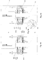
- Fig. 1 presents an embodiment of a twin-tube damper 1 according to the present invention that may be employed in a typical motor vehicle suspension.
- the damper 1 comprises an external tube 2 and a main tube 3 filled with viscous working liquid inside of which a movable piston assembly 4 attached to a piston rod 5 led outside the damper 1 through a sealed piston rod guide 6 is disposed.
- the damper 1 is also provided with a base valve assembly 7 fixed at the other end of the main tube 3.
- the piston assembly 4 makes a sliding fit with the inner surface of the main tube 3 and divides the tube 3 into a rebound chamber 11 (between the piston rod guide 6 and the piston assembly 4) and a compression chamber 12 (between the piston assembly 4 and the base valve assembly 7).
- An additional compensation chamber 13 is located at the other side of the base valve assembly 7.
- compression refers to these elements or parts of elements which are adjacent to the compression chamber 12 or, in a case of working liquid flow direction, it refers to this flow direction that takes place during the compression stroke of the damper.
- rebound refers to these elements or these parts of particular elements which are adjacent to the rebound chamber 11 or, in a case of working liquid flow direction, it refers to this flow direction that takes place during the rebound stroke of the damper.
- the piston assembly 4 is provided with valve assemblies to control the flow of working liquid passing between the rebound chamber 11 and the compression chamber 12 while the piston assembly 4 is in motion.
- the base valve assembly 7 is provided with valve assemblies to control the flow of working liquid passing between the compression chamber 12 and the compensation chamber 13 while the piston assembly 4 is in motion. Nonetheless, as shall be recognised by those skilled in the art from the following description, the invention is also applicable to other damper constructions, including mono-tube dampers provided with a gas compensation chamber separated with a slidable diaphragm from the compression chamber 12.
- the piston assembly 4 comprises a shaped piston body 41 which in this embodiment is composed of a compression member 411 and a rebound member 412 stacked together and surrounded by an annular Teflon sealing 413.
- the compression member 411 of the piston body 41 is provided with a shaped axial protrusion 4111 and the rebound member 412 of the piston body 41 is provided with a corresponding shaped axial recess 4121.
- the shape of the protrusion 4111 matches the shape of the recess 4121, thus forming a kind of a lock preventing mutual rotation of the compression member 411 with respect to the rebound member 412 after the piston body 41 is stacked and assembled together (cf. Fig. 2b ).
- the compression member 411 is also provided at its external rim with a set of equiangularly spaced marking protrusions 418 that visually and tactilely mark the compression side of the piston body 41 enabling for its correct positioning during assembly of the damper.
- the piston body 41 is provided with a first set of five equiangularly spaced sloped channels 414 separated by ten bridges 417 (cf. Fig. 2c ) with a second set of five equiangularly spaced sloped channels 415 enabling for a flow of working liquid while the piston assembly 4 is in motion.
- a first set of five equiangularly spaced sloped channels 414 separated by ten bridges 417 (cf. Fig. 2c ) with a second set of five equiangularly spaced sloped channels 415 enabling for a flow of working liquid while the piston assembly 4 is in motion.
- At the rebound side 4142 of the first sloped channels 414 their entries are connected with each other forming an annular recessed seat enabling for a fluid communication of these entries of the channels 414 with each other at the rebound side of the piston body 41.
- Channels 414 and 415 are sloped with respect to the damper axis, so that the outer compression side 4141 of the channels 414 is radially outer with respect to the inner rebound side annular seat 4142. Likewise the outer rebound side 4152 of the channels 415 is radially outer with respect to the inner compression side annular seat 4151.
- the piston body 41 is further provided with five equiangularly spaced supplementary axial channels 416 which are radially inner both with respect to the first and the second sloped channels 414 and 415. Both compression and rebound sides 4161, 4162 of the supplementary channels 416 also have forms of annular recessed seats enabling for a fluid communication of the respective entries of the channels 416.
- the piston assembly 4 is provided with a rebound side valve assembly 42 formed by a stack of discs comprising two supplementary deflective discs 421, 422 of a similar diameter, a retaining disc 423, four main deflective discs 424, 425 of a similar diameter, a clamp disc 426, and a retainer 427 distancing the rebound side assembly 42 from the piston rod 5.
- the first supplementary disc 421 covers or engages the rebound side annular seat 4162 of the supplementary channels 416 and is covered at the rebound side by the supplementary disc 422 that additionally stiffens the engaging disc 421.
- the engaging supplementary disc 421 is further provided with four equiangularly formed radial recesses or notches 4211 on the outer edge thereof so that a limited flow of working liquid is still possible through the channels 416 and the radial notches 4211 even in a flat, undeflected position of the supplementary discs 421 and 422.
- the inner edges of the supplementary discs 421 and 422 are axially pressed to the piston body 41 by the retaining disc 423 of a smaller diameter that enables their deflection to the rebound side of the piston body 41 after a certain supplementary rebound velocity threshold is reached in order to enable for a more unrestricted flow of working liquid.
- the first main disc 424 abuts the retaining disc 423 and covers or engages the inner rebound side annular seat 4142 of the first sloped channels 414.
- the disc 424 is covered at the rebound side by the stack of three main discs 425 that additionally stiffens the engaging disc 424.
- the engaging main disc 424 is also provided with four equiangularly formed radial recesses or notches 4241 on the outer edge thereof so that a limited flow of working liquid is still possible through the channels 414 and the radial notches 4241 even in a flat, undeflected position of the main discs 424 and 425.
- the main discs 424 and 425 may also deflect to the rebound side of the piston body 41 after a certain main compression velocity threshold is reached in order to enable for a more unrestricted flow of working liquid.
- the piston assembly is provided with a compression side valve assembly 43 having construction similar to the rebound side valve assembly 42 and formed by a stack of discs comprising a supplementary deflective disc 432, a retaining disc 433, six main deflective discs 434, 435 of a similar diameter, a clamp disc 436, and a retainer 437.
- the first supplementary disc 432 covers or engages the compression side annular seat 4161 of the supplementary channels 416 and is axially pressed to the piston body 41 by the retaining disc 433 of a smaller diameter that enables the engaging disc 432 to deflect to the compression side of the piston body 41 after a certain supplementary compression velocity threshold is reached in order to enable for a flow of working liquid.
- the first main disc 434 abuts the retaining disc 433 and covers or engages the inner compression side annular seat 4151 of the second sloped channels 415.
- the disc 434 is covered at the compression side by the stack of five main discs 435 that additionally stiffen engaging disc 434.
- the engaging main disc 434 is also provided with four equiangularly formed radial recesses or notches 4341 on the outer edge thereof so that a limited flow of working liquid is still possible through the channels 415 and the radial notches 4341 even in a flat, undeflected position of the main discs 434 and 435.
- the main discs 434 and 435 may also deflect to the compression side of the piston body 41 after a certain main rebound velocity threshold is reached in order to enable for a more unrestricted flow of working liquid.
- All the components of the piston assembly 4 are fixed on an axial protrusion 51 of the piston rod 5 by means of a nut 44 screwed on an internal thread of the protrusion 51 so that the inner edges of all the discs 421, 422, 424, 425, 432, 434 and 435 are axially fixed which enables for their deflection.
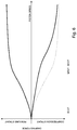
- Figs. 4a-4d illustrates the functionality of the piston assembly during a compression stroke.
- Fig. 4a illustrates a situation that takes place when the velocity of the piston rod 5 is low.
- working liquid flows from the compression chamber 12 to the rebound chamber 11 via pathways A and B.
- Flowing through the pathway A working liquid enters the first sloped channels 414 through their open entries and flows out through the inner rebound side annular seat 4142 and the notches 4241 of the main deflective notched disc 424.
- its pressure remains below the main compression velocity threshold and is insufficient to deflect the main discs 424 and 425.
- working liquid flows through the notches 4341 of the main deflective notched disc 434 to the inner compression side annular seat 4151 and through the second sloped channels 415 flows out at their outer rebound side 4152.
- working liquid flows through the notches 4211 of the supplementary deflective notched disc 421 and fills the supplementary channels 416, but in this velocity range its pressure remains below the supplementary compression velocity threshold and is insufficient to deflect the supplementary deflective disc 432.
- Some embodiments of the invention might also enable for a flow of working liquid through the notches 4211 of the engaging supplementary disc 421 and supplementary channels 416, in order to eventually deflect the disc 432. Nonetheless, this would require for a provision of certain restrictions in the first sloped channels 414.
- the rebound side 42 and the compression side 43 valve assemblies are not symmetrical: there are four main discs 424, 425 and two supplementary disc 421, 422 on the rebound side 42 as compared to six main discs 434, 435 and one supplementary disc 432 on the compression side 43, and no notched supplementary disc is present on the compression side 43.
- the construction and shaping of the piston body 41 is highly symmetrical and the discs on both sides are unified that is the disc 424 is the same as the disc 434, etc.
- Fig. 6 shows a damping force characteristics of the damper shown in Figs. 1-5 and described above during compression and rebound strokes (solid line) and, as an illustration, a characteristic of the damper devoid of the notched supplementary disc 421, that is a situation in which a fluid communication of the supplementary channels 416 with the rebound chamber 11 and the compression chamber 12 is suppressed, during compression stroke (dashed line).
- the damping force is generated solely by the frictional resistance of the notches 4241.
- the engaging supplementary disc 432 of the compression side valve assembly 43 deflects enabling for a smoother increase of the damping force.
- the main compression velocity threshold (MVCT) triggers deflection of the main discs 424 and 454.
- the number, thickness and/or material of the deflective discs 424 and 425 or the discs 434 and 435, the number and the area of the optional notches 4211, 4241, the number and the cross-flow area of the channels 414, 415 and 416 provide excellent capabilities for setting various pressure thresholds and flow restrictions to be generated for working liquid passing between the rebound chamber 11 and the compression chamber 12 along the various flow pathways within the piston body 41, while the piston assembly 4 is in motion.
- This in turn provides virtually unlimited capabilities for shaping and tuning a preferable damping force characteristics of the damper independently for the compression and the rebound stroke and for various ranges of the piston velocity.
- discs 421, 422, 424, 425, 432, 434 and 435 disclosed in the preferred embodiment described above are deflective (i.e. their inner edges are axially fixed) it may appear advantageous to employ all or some discs featuring other functionality such as stiff axially displaceable or floating discs or discs biased with spring or springs.
Landscapes
- Engineering & Computer Science (AREA)
- General Engineering & Computer Science (AREA)
- Mechanical Engineering (AREA)
- Fluid-Damping Devices (AREA)
Priority Applications (1)
| Application Number | Priority Date | Filing Date | Title |
|---|---|---|---|
| PL17001576T PL3299663T3 (pl) | 2016-09-22 | 2017-09-22 | Amortyzator hydrauliczny zawierający zespół tłokowy o krzyżowym układzie przepływu |
Applications Claiming Priority (2)
| Application Number | Priority Date | Filing Date | Title |
|---|---|---|---|
| US201662398038P | 2016-09-22 | 2016-09-22 | |
| US15/681,287 US10239376B2 (en) | 2016-09-22 | 2017-08-18 | Hydraulic damper with an x-flow piston assembly |
Publications (2)
| Publication Number | Publication Date |
|---|---|
| EP3299663A1 true EP3299663A1 (de) | 2018-03-28 |
| EP3299663B1 EP3299663B1 (de) | 2019-11-06 |
Family
ID=59966545
Family Applications (1)
| Application Number | Title | Priority Date | Filing Date |
|---|---|---|---|
| EP17001576.2A Active EP3299663B1 (de) | 2016-09-22 | 2017-09-22 | Hydraulikdämpfer mit einer x-fluss-kolbenanordnung |
Country Status (5)
| Country | Link |
|---|---|
| US (1) | US10239376B2 (de) |
| EP (1) | EP3299663B1 (de) |
| CN (1) | CN107606031B (de) |
| ES (1) | ES2770432T3 (de) |
| PL (1) | PL3299663T3 (de) |
Families Citing this family (2)
| Publication number | Priority date | Publication date | Assignee | Title |
|---|---|---|---|---|
| CN114934968B (zh) * | 2022-03-23 | 2024-08-16 | 武汉鑫拓力工程技术有限公司 | 一种低指数粘滞阻尼器 |
| CN119802132B (zh) * | 2024-03-20 | 2025-12-05 | 北京京西重工有限公司 | 阻尼器组件及用于阻尼器组件的活塞 |
Citations (11)
| Publication number | Priority date | Publication date | Assignee | Title |
|---|---|---|---|---|
| US5148897A (en) | 1991-07-18 | 1992-09-22 | Monroe Auto Equipment Company | Piston valving for shock absorbers |
| JPH11153173A (ja) * | 1997-11-21 | 1999-06-08 | Kayaba Ind Co Ltd | 減衰バルブ構造 |
| JP2000055103A (ja) | 1998-08-06 | 2000-02-22 | Yamaha Motor Co Ltd | 油圧緩衝器 |
| US20010009214A1 (en) * | 2000-01-21 | 2001-07-26 | Akira Tanaka | Hydraulic damper for suspension systems |
| US20050056505A1 (en) * | 2003-09-15 | 2005-03-17 | Stefan Deferme | Monotube piston valving system with selective bleed |
| US20060283676A1 (en) * | 2005-06-21 | 2006-12-21 | Stefan Deferme | Four-piece piston |
| US20090000891A1 (en) * | 2007-06-29 | 2009-01-01 | Masaru Kouyama | Shock absorber |
| US20100163355A1 (en) | 2008-12-25 | 2010-07-01 | Hiroyuki Yamaguchi | Shock absorber |
| US20100294604A1 (en) | 2009-05-20 | 2010-11-25 | Kayaba Industry Co., Ltd. | Damping mechanism |
| US20140262655A1 (en) * | 2013-03-15 | 2014-09-18 | Tenneco Automotive Operating Company Inc. | Piston assembly with open bleed |
| WO2014156445A1 (ja) | 2013-03-25 | 2014-10-02 | カヤバ工業株式会社 | 減衰バルブ |
Family Cites Families (20)
| Publication number | Priority date | Publication date | Assignee | Title |
|---|---|---|---|---|
| US374080A (en) | 1887-11-29 | Speed-governor for elevators | ||
| DE4110023A1 (de) | 1991-03-27 | 1992-10-01 | Ringsdorff Werke Gmbh | Stossdaempferkolben aus ungleichen, gefuegten teilen |
| US4615420A (en) * | 1984-01-23 | 1986-10-07 | Ford Motor Company | Piston assembly for shock absorber |
| DE3832625C2 (de) | 1987-10-13 | 1999-06-24 | Hauni Werke Koerber & Co Kg | Schwingungsdämpfer mit veränderbarer Dämpfungscharakteristik |
| JPH0292154U (de) * | 1989-01-10 | 1990-07-23 | ||
| JPH0369836A (ja) * | 1989-08-09 | 1991-03-26 | Kayaba Ind Co Ltd | 油圧緩衝器のバルブ装置 |
| JP2937580B2 (ja) | 1991-10-16 | 1999-08-23 | 功二 橋本 | 高耐食アモルファス合金 |
| JP4844945B2 (ja) | 1999-06-09 | 2011-12-28 | 日立オートモティブシステムズ株式会社 | 油圧ダンパ |
| DE10013638C1 (de) * | 2000-03-18 | 2001-09-20 | Krupp Bilstein Gmbh | Stoßdämpferkolben, bestehend aus zwei Kolbenhälften |
| KR100505122B1 (ko) | 2000-11-24 | 2005-08-03 | 주식회사 만도 | 쇽 업소버의 피스톤 밸브 |
| DE10245404A1 (de) | 2002-09-28 | 2004-04-08 | Gkn Sinter Metals Gmbh | Pulvermetallurgisch hergestellter Kolbenkörper mit Stützstegen und Verfahren zu seiner Herstellung |
| JP2007120726A (ja) | 2005-10-31 | 2007-05-17 | Hitachi Ltd | 油圧緩衝器 |
| KR100773363B1 (ko) | 2006-01-23 | 2007-11-05 | 주식회사 만도 | 선형의 감쇠력 특성 구현을 위한 쇽업소버 |
| US20080185246A1 (en) | 2007-02-02 | 2008-08-07 | Mando Corporation | Damping force variable shock absorber |
| US8069964B2 (en) | 2007-06-21 | 2011-12-06 | Tenneco Automotive Operating Company Inc. | Junction bleed |
| SE0702798L (sv) | 2007-12-14 | 2009-04-28 | Oehlins Racing Ab | Stötdämpare med ökande dämpkraft |
| JP5115814B2 (ja) | 2008-05-30 | 2013-01-09 | 日立オートモティブシステムズ株式会社 | 緩衝器 |
| JP5695507B2 (ja) | 2011-06-08 | 2015-04-08 | カヤバ工業株式会社 | バルブ構造 |
| WO2013159276A1 (en) | 2012-04-23 | 2013-10-31 | Beijingwest Industries Co., Ltd. | A hydraulic suspension damper with a floating disc valve |
| JP2017044240A (ja) * | 2015-08-25 | 2017-03-02 | 株式会社ショーワ | 圧力緩衝装置 |
-
2017
- 2017-08-18 US US15/681,287 patent/US10239376B2/en active Active
- 2017-08-29 CN CN201710754819.0A patent/CN107606031B/zh active Active
- 2017-09-22 ES ES17001576T patent/ES2770432T3/es active Active
- 2017-09-22 EP EP17001576.2A patent/EP3299663B1/de active Active
- 2017-09-22 PL PL17001576T patent/PL3299663T3/pl unknown
Patent Citations (11)
| Publication number | Priority date | Publication date | Assignee | Title |
|---|---|---|---|---|
| US5148897A (en) | 1991-07-18 | 1992-09-22 | Monroe Auto Equipment Company | Piston valving for shock absorbers |
| JPH11153173A (ja) * | 1997-11-21 | 1999-06-08 | Kayaba Ind Co Ltd | 減衰バルブ構造 |
| JP2000055103A (ja) | 1998-08-06 | 2000-02-22 | Yamaha Motor Co Ltd | 油圧緩衝器 |
| US20010009214A1 (en) * | 2000-01-21 | 2001-07-26 | Akira Tanaka | Hydraulic damper for suspension systems |
| US20050056505A1 (en) * | 2003-09-15 | 2005-03-17 | Stefan Deferme | Monotube piston valving system with selective bleed |
| US20060283676A1 (en) * | 2005-06-21 | 2006-12-21 | Stefan Deferme | Four-piece piston |
| US20090000891A1 (en) * | 2007-06-29 | 2009-01-01 | Masaru Kouyama | Shock absorber |
| US20100163355A1 (en) | 2008-12-25 | 2010-07-01 | Hiroyuki Yamaguchi | Shock absorber |
| US20100294604A1 (en) | 2009-05-20 | 2010-11-25 | Kayaba Industry Co., Ltd. | Damping mechanism |
| US20140262655A1 (en) * | 2013-03-15 | 2014-09-18 | Tenneco Automotive Operating Company Inc. | Piston assembly with open bleed |
| WO2014156445A1 (ja) | 2013-03-25 | 2014-10-02 | カヤバ工業株式会社 | 減衰バルブ |
Also Published As
| Publication number | Publication date |
|---|---|
| CN107606031A (zh) | 2018-01-19 |
| ES2770432T3 (es) | 2020-07-01 |
| PL3299663T3 (pl) | 2020-05-18 |
| EP3299663B1 (de) | 2019-11-06 |
| CN107606031B (zh) | 2019-11-29 |
| US10239376B2 (en) | 2019-03-26 |
| US20180079270A1 (en) | 2018-03-22 |
Similar Documents
| Publication | Publication Date | Title |
|---|---|---|
| US9182005B2 (en) | Hydraulic suspension damper with a floating disc valve | |
| EP3239556B1 (de) | Hydraulischer dämpfer mit einer hydraulischen stoppanordnung | |
| JP7224383B2 (ja) | 緩衝器 | |
| EP2828546B1 (de) | Hydraulischer dämpfer mit verstellbarer rückschlagventilanordnung | |
| EP3489540B1 (de) | Stossdämpfer mit hydraulischem kompressionsabsperrventil | |
| KR102523320B1 (ko) | 완충기 | |
| EP3739234B1 (de) | Dämpferanordnung und kolben für eine dämpferanordnung | |
| CN108050195A (zh) | 具有液压止动装置的液压阻尼器 | |
| CN112360913A (zh) | 液压阻尼器和用于液压阻尼器组件的活塞 | |
| US10830304B2 (en) | Frequency-selective damper valve, and shock absorber and piston having such valve | |
| US12410847B2 (en) | Shock absorber | |
| EP3299663B1 (de) | Hydraulikdämpfer mit einer x-fluss-kolbenanordnung | |
| US12578003B2 (en) | Hydraulic compression stop with closable windows | |
| JP6800056B2 (ja) | 緩衝器 | |
| US10690211B2 (en) | Shock absorber with improved piston architecture | |
| JP7154166B2 (ja) | 緩衝器 | |
| JP7154167B2 (ja) | 緩衝器 | |
| US20240151290A1 (en) | Shock absorber and frequency sensitive mechanism | |
| JP2025076640A (ja) | 緩衝器 |
Legal Events
| Date | Code | Title | Description |
|---|---|---|---|
| PUAI | Public reference made under article 153(3) epc to a published international application that has entered the european phase |
Free format text: ORIGINAL CODE: 0009012 |
|
| STAA | Information on the status of an ep patent application or granted ep patent |
Free format text: STATUS: THE APPLICATION HAS BEEN PUBLISHED |
|
| AK | Designated contracting states |
Kind code of ref document: A1 Designated state(s): AL AT BE BG CH CY CZ DE DK EE ES FI FR GB GR HR HU IE IS IT LI LT LU LV MC MK MT NL NO PL PT RO RS SE SI SK SM TR |
|
| AX | Request for extension of the european patent |
Extension state: BA ME |
|
| STAA | Information on the status of an ep patent application or granted ep patent |
Free format text: STATUS: REQUEST FOR EXAMINATION WAS MADE |
|
| 17P | Request for examination filed |
Effective date: 20180928 |
|
| RBV | Designated contracting states (corrected) |
Designated state(s): AL AT BE BG CH CY CZ DE DK EE ES FI FR GB GR HR HU IE IS IT LI LT LU LV MC MK MT NL NO PL PT RO RS SE SI SK SM TR |
|
| GRAP | Despatch of communication of intention to grant a patent |
Free format text: ORIGINAL CODE: EPIDOSNIGR1 |
|
| STAA | Information on the status of an ep patent application or granted ep patent |
Free format text: STATUS: GRANT OF PATENT IS INTENDED |
|
| INTG | Intention to grant announced |
Effective date: 20190403 |
|
| RAP1 | Party data changed (applicant data changed or rights of an application transferred) |
Owner name: BEIJINGWEST INDUSTRIES CO., LTD. |
|
| GRAS | Grant fee paid |
Free format text: ORIGINAL CODE: EPIDOSNIGR3 |
|
| GRAA | (expected) grant |
Free format text: ORIGINAL CODE: 0009210 |
|
| STAA | Information on the status of an ep patent application or granted ep patent |
Free format text: STATUS: THE PATENT HAS BEEN GRANTED |
|
| AK | Designated contracting states |
Kind code of ref document: B1 Designated state(s): AL AT BE BG CH CY CZ DE DK EE ES FI FR GB GR HR HU IE IS IT LI LT LU LV MC MK MT NL NO PL PT RO RS SE SI SK SM TR |
|
| REG | Reference to a national code |
Ref country code: GB Ref legal event code: FG4D |
|
| REG | Reference to a national code |
Ref country code: CH Ref legal event code: EP Ref country code: AT Ref legal event code: REF Ref document number: 1199132 Country of ref document: AT Kind code of ref document: T Effective date: 20191115 |
|
| REG | Reference to a national code |
Ref country code: IE Ref legal event code: FG4D |
|
| REG | Reference to a national code |
Ref country code: DE Ref legal event code: R096 Ref document number: 602017008295 Country of ref document: DE |
|
| REG | Reference to a national code |
Ref country code: RO Ref legal event code: EPE |
|
| REG | Reference to a national code |
Ref country code: NL Ref legal event code: MP Effective date: 20191106 |
|
| REG | Reference to a national code |
Ref country code: LT Ref legal event code: MG4D |
|
| PG25 | Lapsed in a contracting state [announced via postgrant information from national office to epo] |
Ref country code: FI Free format text: LAPSE BECAUSE OF FAILURE TO SUBMIT A TRANSLATION OF THE DESCRIPTION OR TO PAY THE FEE WITHIN THE PRESCRIBED TIME-LIMIT Effective date: 20191106 Ref country code: BG Free format text: LAPSE BECAUSE OF FAILURE TO SUBMIT A TRANSLATION OF THE DESCRIPTION OR TO PAY THE FEE WITHIN THE PRESCRIBED TIME-LIMIT Effective date: 20200206 Ref country code: SE Free format text: LAPSE BECAUSE OF FAILURE TO SUBMIT A TRANSLATION OF THE DESCRIPTION OR TO PAY THE FEE WITHIN THE PRESCRIBED TIME-LIMIT Effective date: 20191106 Ref country code: LV Free format text: LAPSE BECAUSE OF FAILURE TO SUBMIT A TRANSLATION OF THE DESCRIPTION OR TO PAY THE FEE WITHIN THE PRESCRIBED TIME-LIMIT Effective date: 20191106 Ref country code: NL Free format text: LAPSE BECAUSE OF FAILURE TO SUBMIT A TRANSLATION OF THE DESCRIPTION OR TO PAY THE FEE WITHIN THE PRESCRIBED TIME-LIMIT Effective date: 20191106 Ref country code: LT Free format text: LAPSE BECAUSE OF FAILURE TO SUBMIT A TRANSLATION OF THE DESCRIPTION OR TO PAY THE FEE WITHIN THE PRESCRIBED TIME-LIMIT Effective date: 20191106 Ref country code: GR Free format text: LAPSE BECAUSE OF FAILURE TO SUBMIT A TRANSLATION OF THE DESCRIPTION OR TO PAY THE FEE WITHIN THE PRESCRIBED TIME-LIMIT Effective date: 20200207 Ref country code: PT Free format text: LAPSE BECAUSE OF FAILURE TO SUBMIT A TRANSLATION OF THE DESCRIPTION OR TO PAY THE FEE WITHIN THE PRESCRIBED TIME-LIMIT Effective date: 20200306 Ref country code: NO Free format text: LAPSE BECAUSE OF FAILURE TO SUBMIT A TRANSLATION OF THE DESCRIPTION OR TO PAY THE FEE WITHIN THE PRESCRIBED TIME-LIMIT Effective date: 20200206 |
|
| PG25 | Lapsed in a contracting state [announced via postgrant information from national office to epo] |
Ref country code: HR Free format text: LAPSE BECAUSE OF FAILURE TO SUBMIT A TRANSLATION OF THE DESCRIPTION OR TO PAY THE FEE WITHIN THE PRESCRIBED TIME-LIMIT Effective date: 20191106 Ref country code: IS Free format text: LAPSE BECAUSE OF FAILURE TO SUBMIT A TRANSLATION OF THE DESCRIPTION OR TO PAY THE FEE WITHIN THE PRESCRIBED TIME-LIMIT Effective date: 20200306 Ref country code: RS Free format text: LAPSE BECAUSE OF FAILURE TO SUBMIT A TRANSLATION OF THE DESCRIPTION OR TO PAY THE FEE WITHIN THE PRESCRIBED TIME-LIMIT Effective date: 20191106 |
|
| PG25 | Lapsed in a contracting state [announced via postgrant information from national office to epo] |
Ref country code: AL Free format text: LAPSE BECAUSE OF FAILURE TO SUBMIT A TRANSLATION OF THE DESCRIPTION OR TO PAY THE FEE WITHIN THE PRESCRIBED TIME-LIMIT Effective date: 20191106 |
|
| REG | Reference to a national code |
Ref country code: ES Ref legal event code: FG2A Ref document number: 2770432 Country of ref document: ES Kind code of ref document: T3 Effective date: 20200701 |
|
| PG25 | Lapsed in a contracting state [announced via postgrant information from national office to epo] |
Ref country code: EE Free format text: LAPSE BECAUSE OF FAILURE TO SUBMIT A TRANSLATION OF THE DESCRIPTION OR TO PAY THE FEE WITHIN THE PRESCRIBED TIME-LIMIT Effective date: 20191106 Ref country code: DK Free format text: LAPSE BECAUSE OF FAILURE TO SUBMIT A TRANSLATION OF THE DESCRIPTION OR TO PAY THE FEE WITHIN THE PRESCRIBED TIME-LIMIT Effective date: 20191106 |
|
| REG | Reference to a national code |
Ref country code: DE Ref legal event code: R097 Ref document number: 602017008295 Country of ref document: DE |
|
| REG | Reference to a national code |
Ref country code: AT Ref legal event code: MK05 Ref document number: 1199132 Country of ref document: AT Kind code of ref document: T Effective date: 20191106 |
|
| PG25 | Lapsed in a contracting state [announced via postgrant information from national office to epo] |
Ref country code: SM Free format text: LAPSE BECAUSE OF FAILURE TO SUBMIT A TRANSLATION OF THE DESCRIPTION OR TO PAY THE FEE WITHIN THE PRESCRIBED TIME-LIMIT Effective date: 20191106 Ref country code: SK Free format text: LAPSE BECAUSE OF FAILURE TO SUBMIT A TRANSLATION OF THE DESCRIPTION OR TO PAY THE FEE WITHIN THE PRESCRIBED TIME-LIMIT Effective date: 20191106 |
|
| PLBE | No opposition filed within time limit |
Free format text: ORIGINAL CODE: 0009261 |
|
| STAA | Information on the status of an ep patent application or granted ep patent |
Free format text: STATUS: NO OPPOSITION FILED WITHIN TIME LIMIT |
|
| 26N | No opposition filed |
Effective date: 20200807 |
|
| PG25 | Lapsed in a contracting state [announced via postgrant information from national office to epo] |
Ref country code: AT Free format text: LAPSE BECAUSE OF FAILURE TO SUBMIT A TRANSLATION OF THE DESCRIPTION OR TO PAY THE FEE WITHIN THE PRESCRIBED TIME-LIMIT Effective date: 20191106 Ref country code: SI Free format text: LAPSE BECAUSE OF FAILURE TO SUBMIT A TRANSLATION OF THE DESCRIPTION OR TO PAY THE FEE WITHIN THE PRESCRIBED TIME-LIMIT Effective date: 20191106 |
|
| REG | Reference to a national code |
Ref country code: CH Ref legal event code: PL |
|
| REG | Reference to a national code |
Ref country code: BE Ref legal event code: MM Effective date: 20200930 |
|
| PG25 | Lapsed in a contracting state [announced via postgrant information from national office to epo] |
Ref country code: LU Free format text: LAPSE BECAUSE OF NON-PAYMENT OF DUE FEES Effective date: 20200922 |
|
| PG25 | Lapsed in a contracting state [announced via postgrant information from national office to epo] |
Ref country code: BE Free format text: LAPSE BECAUSE OF NON-PAYMENT OF DUE FEES Effective date: 20200930 Ref country code: CH Free format text: LAPSE BECAUSE OF NON-PAYMENT OF DUE FEES Effective date: 20200930 Ref country code: LI Free format text: LAPSE BECAUSE OF NON-PAYMENT OF DUE FEES Effective date: 20200930 Ref country code: IE Free format text: LAPSE BECAUSE OF NON-PAYMENT OF DUE FEES Effective date: 20200922 |
|
| PG25 | Lapsed in a contracting state [announced via postgrant information from national office to epo] |
Ref country code: TR Free format text: LAPSE BECAUSE OF FAILURE TO SUBMIT A TRANSLATION OF THE DESCRIPTION OR TO PAY THE FEE WITHIN THE PRESCRIBED TIME-LIMIT Effective date: 20191106 Ref country code: MT Free format text: LAPSE BECAUSE OF FAILURE TO SUBMIT A TRANSLATION OF THE DESCRIPTION OR TO PAY THE FEE WITHIN THE PRESCRIBED TIME-LIMIT Effective date: 20191106 Ref country code: CY Free format text: LAPSE BECAUSE OF FAILURE TO SUBMIT A TRANSLATION OF THE DESCRIPTION OR TO PAY THE FEE WITHIN THE PRESCRIBED TIME-LIMIT Effective date: 20191106 |
|
| PG25 | Lapsed in a contracting state [announced via postgrant information from national office to epo] |
Ref country code: MK Free format text: LAPSE BECAUSE OF FAILURE TO SUBMIT A TRANSLATION OF THE DESCRIPTION OR TO PAY THE FEE WITHIN THE PRESCRIBED TIME-LIMIT Effective date: 20191106 Ref country code: MC Free format text: LAPSE BECAUSE OF FAILURE TO SUBMIT A TRANSLATION OF THE DESCRIPTION OR TO PAY THE FEE WITHIN THE PRESCRIBED TIME-LIMIT Effective date: 20191106 |
|
| PGFP | Annual fee paid to national office [announced via postgrant information from national office to epo] |
Ref country code: DE Payment date: 20250730 Year of fee payment: 9 |
|
| PGFP | Annual fee paid to national office [announced via postgrant information from national office to epo] |
Ref country code: PL Payment date: 20250805 Year of fee payment: 9 Ref country code: IT Payment date: 20250825 Year of fee payment: 9 |
|
| PGFP | Annual fee paid to national office [announced via postgrant information from national office to epo] |
Ref country code: GB Payment date: 20250731 Year of fee payment: 9 |
|
| PGFP | Annual fee paid to national office [announced via postgrant information from national office to epo] |
Ref country code: FR Payment date: 20250808 Year of fee payment: 9 |
|
| PGFP | Annual fee paid to national office [announced via postgrant information from national office to epo] |
Ref country code: CZ Payment date: 20250905 Year of fee payment: 9 |
|
| PGFP | Annual fee paid to national office [announced via postgrant information from national office to epo] |
Ref country code: RO Payment date: 20250828 Year of fee payment: 9 |
|
| PGFP | Annual fee paid to national office [announced via postgrant information from national office to epo] |
Ref country code: ES Payment date: 20251015 Year of fee payment: 9 |