EP3299770B1 - Induktive sensorvorrichtung - Google Patents
Induktive sensorvorrichtung Download PDFInfo
- Publication number
- EP3299770B1 EP3299770B1 EP16190081.6A EP16190081A EP3299770B1 EP 3299770 B1 EP3299770 B1 EP 3299770B1 EP 16190081 A EP16190081 A EP 16190081A EP 3299770 B1 EP3299770 B1 EP 3299770B1
- Authority
- EP
- European Patent Office
- Prior art keywords
- receive coil
- scale
- measuring direction
- receive
- coil set
- Prior art date
- Legal status (The legal status is an assumption and is not a legal conclusion. Google has not performed a legal analysis and makes no representation as to the accuracy of the status listed.)
- Active
Links
Images


Classifications
-
- G—PHYSICS
- G01—MEASURING; TESTING
- G01D—MEASURING NOT SPECIALLY ADAPTED FOR A SPECIFIC VARIABLE; ARRANGEMENTS FOR MEASURING TWO OR MORE VARIABLES NOT COVERED IN A SINGLE OTHER SUBCLASS; TARIFF METERING APPARATUS; MEASURING OR TESTING NOT OTHERWISE PROVIDED FOR
- G01D5/00—Mechanical means for transferring the output of a sensing member; Means for converting the output of a sensing member to another variable where the form or nature of the sensing member does not constrain the means for converting; Transducers not specially adapted for a specific variable
- G01D5/12—Mechanical means for transferring the output of a sensing member; Means for converting the output of a sensing member to another variable where the form or nature of the sensing member does not constrain the means for converting; Transducers not specially adapted for a specific variable using electric or magnetic means
- G01D5/14—Mechanical means for transferring the output of a sensing member; Means for converting the output of a sensing member to another variable where the form or nature of the sensing member does not constrain the means for converting; Transducers not specially adapted for a specific variable using electric or magnetic means influencing the magnitude of a current or voltage
- G01D5/20—Mechanical means for transferring the output of a sensing member; Means for converting the output of a sensing member to another variable where the form or nature of the sensing member does not constrain the means for converting; Transducers not specially adapted for a specific variable using electric or magnetic means influencing the magnitude of a current or voltage by varying inductance, e.g. by a movable armature
- G01D5/204—Mechanical means for transferring the output of a sensing member; Means for converting the output of a sensing member to another variable where the form or nature of the sensing member does not constrain the means for converting; Transducers not specially adapted for a specific variable using electric or magnetic means influencing the magnitude of a current or voltage by varying inductance, e.g. by a movable armature by influencing the mutual induction between two or more coils
- G01D5/2053—Mechanical means for transferring the output of a sensing member; Means for converting the output of a sensing member to another variable where the form or nature of the sensing member does not constrain the means for converting; Transducers not specially adapted for a specific variable using electric or magnetic means influencing the magnitude of a current or voltage by varying inductance, e.g. by a movable armature by influencing the mutual induction between two or more coils by a movable non-ferromagnetic conductive element
-
- G—PHYSICS
- G01—MEASURING; TESTING
- G01B—MEASURING LENGTH, THICKNESS OR SIMILAR LINEAR DIMENSIONS; MEASURING ANGLES; MEASURING AREAS; MEASURING IRREGULARITIES OF SURFACES OR CONTOURS
- G01B3/00—Measuring instruments characterised by the use of mechanical techniques
- G01B3/20—Slide gauges
- G01B3/205—Slide gauges provided with a counter for digital indication of the measured dimension
-
- G—PHYSICS
- G01—MEASURING; TESTING
- G01B—MEASURING LENGTH, THICKNESS OR SIMILAR LINEAR DIMENSIONS; MEASURING ANGLES; MEASURING AREAS; MEASURING IRREGULARITIES OF SURFACES OR CONTOURS
- G01B7/00—Measuring arrangements characterised by the use of electric or magnetic techniques
- G01B7/003—Measuring arrangements characterised by the use of electric or magnetic techniques for measuring position, not involving coordinate determination
-
- G—PHYSICS
- G01—MEASURING; TESTING
- G01D—MEASURING NOT SPECIALLY ADAPTED FOR A SPECIFIC VARIABLE; ARRANGEMENTS FOR MEASURING TWO OR MORE VARIABLES NOT COVERED IN A SINGLE OTHER SUBCLASS; TARIFF METERING APPARATUS; MEASURING OR TESTING NOT OTHERWISE PROVIDED FOR
- G01D5/00—Mechanical means for transferring the output of a sensing member; Means for converting the output of a sensing member to another variable where the form or nature of the sensing member does not constrain the means for converting; Transducers not specially adapted for a specific variable
- G01D5/12—Mechanical means for transferring the output of a sensing member; Means for converting the output of a sensing member to another variable where the form or nature of the sensing member does not constrain the means for converting; Transducers not specially adapted for a specific variable using electric or magnetic means
- G01D5/244—Mechanical means for transferring the output of a sensing member; Means for converting the output of a sensing member to another variable where the form or nature of the sensing member does not constrain the means for converting; Transducers not specially adapted for a specific variable using electric or magnetic means influencing characteristics of pulses or pulse trains; generating pulses or pulse trains
- G01D5/248—Mechanical means for transferring the output of a sensing member; Means for converting the output of a sensing member to another variable where the form or nature of the sensing member does not constrain the means for converting; Transducers not specially adapted for a specific variable using electric or magnetic means influencing characteristics of pulses or pulse trains; generating pulses or pulse trains by varying pulse repetition frequency
-
- G—PHYSICS
- G01—MEASURING; TESTING
- G01D—MEASURING NOT SPECIALLY ADAPTED FOR A SPECIFIC VARIABLE; ARRANGEMENTS FOR MEASURING TWO OR MORE VARIABLES NOT COVERED IN A SINGLE OTHER SUBCLASS; TARIFF METERING APPARATUS; MEASURING OR TESTING NOT OTHERWISE PROVIDED FOR
- G01D5/00—Mechanical means for transferring the output of a sensing member; Means for converting the output of a sensing member to another variable where the form or nature of the sensing member does not constrain the means for converting; Transducers not specially adapted for a specific variable
- G01D5/12—Mechanical means for transferring the output of a sensing member; Means for converting the output of a sensing member to another variable where the form or nature of the sensing member does not constrain the means for converting; Transducers not specially adapted for a specific variable using electric or magnetic means
- G01D5/244—Mechanical means for transferring the output of a sensing member; Means for converting the output of a sensing member to another variable where the form or nature of the sensing member does not constrain the means for converting; Transducers not specially adapted for a specific variable using electric or magnetic means influencing characteristics of pulses or pulse trains; generating pulses or pulse trains
- G01D5/249—Mechanical means for transferring the output of a sensing member; Means for converting the output of a sensing member to another variable where the form or nature of the sensing member does not constrain the means for converting; Transducers not specially adapted for a specific variable using electric or magnetic means influencing characteristics of pulses or pulse trains; generating pulses or pulse trains using pulse code
- G01D5/2497—Absolute encoders
Definitions
- the present invention refers to the technical field of inductive sensor devices.
- inductive sensor devices can be used for determination of a relative position between two parts that are moveable relative to each other in a linear and/or circular direction.
- Such inductive sensor devices can be used for measuring instruments like calipers, micrometer gauges, test indicators, touch probes and other measuring instruments.
- An inductive sensor device is for example disclosed in US 5,886,519 .
- a scale unit is provided with a number of scale elements, arranged in at least one line in a measuring direction.
- the scale elements of one common line have the same scale pitch.
- a sensor unit containing a transmit coil and at least one receive coil is provided for each line of scale elements .
- the transmit coil creates a magnetic field, that is varied by means of the scale elements.
- a field pattern is thus created that is detectable by means of the respective receive coil.
- a receive signal provided by each receive coil can be used to determine a relative position between the sensor unit and the scale. It is proposed that receive coils assigned to different lines of scale elements are provided with different wavelengths respectively. In so doing an absolute position sensor device is obtained.
- the inductive sensor device disclosed in US 6,335,618 B1 provides scale elements that extend in a plane spanned by the measuring direction and a height direction perpendicular to the measurement direction.
- the scale elements have varying dimensions in the height direction depending on their position in measuring direction. In so doing the amplitude of the receive signal is modulated.
- Such an inductive sensor is more sensitive to displacements in the height direction.
- US 7,705,585 B2 shows an inductive sensor device having a scale element with holes.
- the dimension of the holes can vary in measuring direction in order to create an aperiodic pattern for absolute position measurement. Due to the variation of the dimension of the scale element, the sensor device is also sensitive to a displacement in height direction perpendicular to the measurement direction. Moreover, the varying area amount of the holes could lead to reduced signal amplitudes and could make the device sensitive to noise.
- the absolute position sensor device disclosed in EP 2 581 711 A2 proposes to have two lines of scale elements with different pitches for absolute position determination.
- US 9,217,628 proposes an inductive sensor device with one single line of scale elements.
- the at least one receive coil of the sensor unit has along its extension in measuring direction a varying wavelength.
- the receive winding and a transmit winding extend along a scale unit over the entire measurement path.
- Moveable relative to the sensor unit is a target unit that contains two resonant circuits, each having a capacitor and a laminar winding that forms the inductance.
- the resonant circuits have different resonant frequencies.
- the transmit coil of the scale unit is energized by means of two different AC frequencies.
- the target unit position along the scale unit can be determined depending on the two signals received in the receive coil based on the two transmit AC frequencies. This device uses different frequencies for obtaining two receive signals that allow absolute position detection. Such a device is complex and costly.
- US 6 054 851 discloses an inductive sensor device comprising a first coded track used to determine a rough absolute position and a second periodical track used in addition to determine a precise position.
- Document US 2010/0141244 discloses a magnetic position sensor using a single track, wherein the scale period varies along the measurement direction.
- an object of the present invention is to provide a simple inductive sensor device that allows absolute position measurement with high accuracy and requires little space.
- the inductive sensor device comprises, amongst other features, a scale unit having scale elements that are arranged in at least one line extending in a measuring direction.
- the scale elements are adapted to create a field pattern in measuring direction.
- a sensor unit is provided that comprises a receive circuit.
- the receive circuit has at least a first receive coil set and a second receive coil set to detect the field pattern.
- the first and second receive coil sets are displaced relative to each other in measuring direction.
- the sensor unit and the scale unit are moveable relative to each other in measuring direction.
- Each receive coil set includes at least two receive coils.
- One line of scale elements is sufficient but not covered by the invention.
- An additional line of scale elements is used in the invention.
- the scale elements of one common line all have the same dimensions in measuring direction and preferably also in a height direction that extends perpendicular to the measuring direction.
- At least one of the lines of scale elements has a varying pitch or spacing between the scale elements in measuring direction.
- the pitch is equal to the dimension of one scale element in measuring direction plus the spacing in between two directly adjacent scale elements. Since the dimension in measuring direction of the scale elements in one line is constant, the pitch is varied by means of a variation of the spacing between two directly adjacent scale elements. Preferably this spacing is defined by means of a non-linear function depending on a position variable that characterizes the position between the scale unit and the sensor unit in measuring direction.
- the receive coil sets each create a respective receive signal that can be used for absolute position detection.
- the function that defines the spacing between the scale elements can be determined in order to provide for a sufficient long range in which absolute position determination is possible and in order to make the sensor device less sensitive to noise.
- the receive circuit is adapted to determine a first spatial phase of a first receive signal provided by the first receive coil set and a second spatial phase of a second receive signal provided by the second receive coil set.
- the spatial phases of the two receive coil sets have different gradients at one location in measuring direction. Therefore, the phase detection allows for absolute position determination.
- the position determination can be made by using a look-up table or by calculation based on the respective first and second phases.
- the first receive coil set and the second receive coil set are displaced at a coil distance in measuring direction and preferably extend along a common longitudinal axis in measuring direction.
- the coil distance is large enough, so that the first and second receive coil set do not overlap, but a gap exists in between.
- the first receive coil set and the second receive coil set have the same length in measuring direction. More preferably the two receive coil sets can be identical. This means that if one of the receive coil sets is shifted in measuring direction until it covers the respective other receive coil set, the two receive coil sets coincide.
- the dimension of the first and second receive coil set in height direction can for example substantially correspond to the height of the scale elements.
- the scale unit also comprises an additional line of scale elements that preferably all have the same dimension in measuring direction and optionally also in height direction.
- this additional or second line of scale elements can have a constant spacing and thus a constant pitch that does not vary along the measuring direction.
- this additional or second line can have a varying spacing, wherein the variation of the spacing of the second line differs from the variation of the spacing of the first line of scale elements.
- the first line of scale elements can have a first spacing defined by a non-linear first function and the second line of scale elements can have a second spacing defined by a preferably linear second function.
- Such additional lines allow a coarse and at least one finer resolution for the position determination and therefore an extended measurement range in measuring direction can be achieved without decrease of the accuracy.
- the sensor unit contains a third receive coil set having at least one receive coil assigned to the additional line of scale elements.
- the third receive coil set is preferably arranged adjacent to the first and/or second receive coil set in height direction.
- the third receive coil set has a length larger than the length of the first and/or second receive coil sets in measuring direction.
- the length of the third receive coil set is for example 1.5 times to 2.5 times longer than the first and/or second receive coil set.
- Each scale element has two opposite sides in measuring direction, wherein one side forms a loop front and the other side forms a loop back.
- the loop front and the loop back can have identical shapes. In other words, if the loop front would be shifted in measuring direction onto the loop back, the loop front and the loop back would completely coincide.
- the scale element can surround a substantially rectangular area.
- the scale elements contain or are formed by scale loops that are arranged adjacent to each other in measuring direction.
- Each scale element can be formed by one single scale loop.
- Each scale loop can completely surround a loop area and forms a closed loop.
- the scale elements are passive field-influencing elements.
- a transmit circuit is present that comprises at least one transmit coil adapted to create a magnetic field.
- the scale elements vary the magnetic field in order to create the field pattern in measuring direction.
- the transmit circuit is part of the sensor unit.
- a separate transmit coil can be assigned to each of the receive coil sets.
- the transmit coil surrounds the assigned receive coil set. It is also possible that one transmit coil is provided for each separate line of scale elements, so that one single transmit coil is assigned to the first and second receive coil set.
- All of the coils and/or loops can be laminar.
- the receive coils and optionally also the at least one transmit coil is provided on a circuit board.
- the circuit board can have different layers.
- Each of the receive coils can be formed by a first conductor and/or a second conductor arranged on different layers of the circuit board.
- all of the receive coil sets extend along a respective axis parallel to the measuring direction and that each receive coil has a mirror symmetric contour with regard to this axis.
- FIG. 1 shows a schematic illustration of an exemplary measuring instrument 20 in form of a caliper.
- the caliper is realized as digital caliper for measuring a distance between inside jaws 21 and/or outside jaws 22 of an object.
- a distance is measured by means of an inductive sensor device 23.
- the inductive sensor device 23 includes a scale unit 24 and a sensor unit 25 that are moveable relative to each other in a measuring direction M.
- the scale unit 24 contains a number of scale elements 26 that are arranged in at least one line 27 extending in measuring direction M.
- the scale elements 26 are adapted to create a field pattern P(x) in measuring direction M (compare figure 8 ), wherein x is a position variable that describes the relative position between the sensor unit 25 and the scale unit 24 in measuring direction M and in the present example the position of the sensor unit 25 along the scale unit 24..
- the scale elements 26 contain electrically conductive material.
- the scale elements 26 are not connected with each other, but are separate non-connected elements.
- each scale element 26 is formed by a scale loop 28 and particularly by one single scale loop 28.
- the scale elements 26 or scale loops 28 respectively are in the present example passive field-influencing elements and create the field pattern P(x) by varying or modifying a magnetic field B.
- the inductive sensor device 23 and preferably the sensor unit 25 contains a transmit circuit 32 having at least one transmit coil 33 and an AC voltage source 34 that is connected to the at least one transmit coil 33. Due to the alternating current, the transmit coil 33 creates a magnetic field B having circular field lines around a conductor or loop of the transmit coil 33. Preferably each transmit coil 33 is formed by one single loop.
- the first receive coil set 36 and the second receive coil set 37 extend preferably along a common first longitudinal axis L1 that extends in measuring direction M ( figure 7 ).
- Each receive coil of each receive coil set 36, 37 has a mirror symmetric shape or contour with regard to the first longitudinal axis L1.
- the first and the second receive coil set 36, 37 are identical.
- the first receive coil set 36 can be moved in measuring direction onto the second receive coil set 37, so that both receive coil sets coincide.
- the receive coil sets 36, 37 and optionally also the at least one transmit coil 33 can be arranged on a common circuit board 40.
- a separate transmit coil 33 is assigned to the first receive coil set 36 and the second receive coil set 37.
- the respective transmit coil 33 can surround the associated receive coil set 36, 37 respectively.
- the transmit coils 33 are arranged on one common layer 40a of the circuit board 40. The connection to the AC voltage source 34 is not shown.
- the conductors 41 and 42 have a continuous run between the ends of a respective receive coil in one layer.
- the conductors 41, 42 are short-circuited on one end of the respective receive coil opposite to the terminals 38.
- the distance between crossing locations 43 that are directly adjacent to each other in measuring direction M corresponds to a half wavelength.
- the wavelength w of each receive coil 45 is constant.
- the receive coils 45 first receive coil set 36 and the second receive coil set 37 can have the same wavelength w (compare figure 7 ).
- the length of the first and second receive coil set 36, 37 is equal.
- the first receive coil set 36 and the second receive coil set 37 are offset by a coil distance d from each other along the first longitudinal axis L1.
- the coil distance d is longer than the length of the first receive coil set 36 and the second receive coil set 37 in measuring direction M. Accordingly, a gap is present at the first longitudinal axis L1 between one end of the first receive coil set 36 and the respective adjacent end of the second receive coil set 37.
- the two receive coil sets 36, 37 do not overlap.
- the basic principle of an inductive sensor is shown in figure 4 .
- the at least one transmit coil 33 creates a magnetic field B.
- the magnetic flux through the coil loops 44 of the respective receive coil sets 36, 37 depends on the relative position between the sensor unit 25 and the scale unit 24 in measuring direction M.
- the induced voltages of each receive coil 45 provide a spatial or position phase.
- the two spatial phases are used for an absolute position determination in the receive circuit 35.
- the scale elements 26 are preferably rectangular. They have in measuring direction M a loop front and a loop back at opposite sides that correspond to each other. This means that the loop front can be shifted onto the loop back in measuring direction M so that loop front and loop back coincide completely.
- the loop front and the loop back extend linear in height direction H.
- the second phase ⁇ 2 (x) ramps more quickly than the first phase ⁇ 1 (x). From these two phases the position x can be unambiguously determined.
- the advantage of the present invention is, that both phases are measured from one single track or line 27, so that the required space for the inductive sensor device 23 can be reduced particularly in height direction H.
- Figure 10 shows the range over which the position x can be determined unambiguously by illustrating the locus of the points ( ⁇ 1 (x), ⁇ 2 (x)) by means of increments in the position x, for example increments of 0.02.
- the points in the illustration of figure 10 continue from the right-hand edge at the left-hand edge and from the top edge at the bottom edge.
- the line of locus points thus continuously winds around a torus. In a range where it never crosses itself, each locus point can be unambiguously associated with one specific position value x.
- figure 10 it is schematically shown that, due to noise or other disturbances, a measured point (cross in figure 10 in the right picture) can be offset from the possible locus points.
- the position can then be estimated by using a mathematical function - like the least squares method - in order to find the locus point that is closest to the measured point shown by the cross in figure 10 .
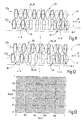
- the invention uses a first line 27a and a second line 27b of scale elements 26 as shown in figures 11 and 12 .
- the first line 27a corresponds to the single line 27 described above to which the first receive coil set 36 and the second receive coil set 37 are assigned.
- the additional second line 27b can have a constant pitch or spacing s of the scale elements in the second line 27b, as shown in figure 11 .
- the spacing in the second line 27b can vary depending on the position x, as schematically illustrated in figure 12 .
- a third receive coil set 50 of the sensor unit 25 is assigned to the second line 27b of scale elements 26. In the present embodiment the length of the third receive coil set 50 is longer than the length of the first and second receive coil sets 36, 37.
- the wavelength w of the receive coils 45 of the third receive coil set 50 is identical to the wavelength w of the receive coils 45 of the first and second receive coil sets 36, 37.
- the third receive coil set 50 can be provided on the circuit board 40.
- An additional third transmit coil 33 can be assigned to the third receive coil set 50 in a similar way,
- the third receive coil set 50 extends in measuring direction M along a second longitudinal axis L2 and is mirror symmetric with regard to this second longitudinal axis L2.
- the second longitudinal axis L2 extends parallel to the first longitudinal axis L1.
- any of the three phases can be used for the most precise resolution for the position determination, preferably the third phase ⁇ 3 (x) having a constant spacing between the scale elements 26.
- both lines 27a and 27b contain a spacing (s(x)) varying in measuring direction M.
- a fine resolution can be obtained in a third step by using one of the individual phases, e.g. the third phase ⁇ 3 (x) to determine the position value x.
- the parameter values of k i in all of the above-mentioned phase functions can be selected in order to reduce the sensitivity against noise.
- the difference in the values of ⁇ 2 (x) should be some multiple of the root mean square noise (RMS noise) on ⁇ 2 (x).
- the difference in the values of ⁇ 1 (x) should be some multiple of the root mean square noise (RMS noise) on ⁇ 1 (x).
- Figure 13 shows an example of locus points for the position x using three phases and the respective phase comparing functions ⁇ 1 (x) and ⁇ 2 (x).
- a low sample rate can be used that reduces power consumption, which is important for measuring instruments that are energized by means of batteries or accumulators or the like. Only phase measurements are necessary that can be implemented by using simple electronic circuits in the evaluation unit 39.
- the coupling C 1 and C 2 can be mixed either with a sinusoidal signal or also with a square wave and the zero crossing timing can be used to determine the phase.
- a lowpass or bandpass filtering can be provided to remove harmonics in the square waves.
- the zero crossing detection can be obtained by using a comparator.
- the scale unit can be positioned so that the end having lower spacing or pitch between the scale elements is assigned to the specific end position of the machine part that is to be measured.
- the present invention relates to an inductive sensor device 23 having a scale unit 24 and a sensor unit 25 that can be moved relative to each other in a measuring direction M.
- the scale unit contains scale elements 26 that are adapted to create a field pattern P(x) in measuring direction M that is detected by means of a receive circuit 35 of the sensor unit 25.
- the receive circuit 35 contains at least a first receive coil set 36 and a second receive coil set 37 that are offset in measuring direction M. In so doing a first spatial phase and a second spatial phase is provided by these receive coil sets 36, 37 respectively. These spatial phases can be used for absolute position determination.
Landscapes
- Physics & Mathematics (AREA)
- General Physics & Mathematics (AREA)
- Transmission And Conversion Of Sensor Element Output (AREA)
- Measurement Of Length, Angles, Or The Like Using Electric Or Magnetic Means (AREA)
Claims (15)
- Induktive Sensoreinrichtung (23) aufweisend:eine Skaleneinheit (24) mit Skalenelementen (26), die in einer ersten Linie (27a) angeordnet sind, die sich in Messrichtung (M) erstreckt, und die dazu eingerichtet sind, ein Feldmuster P(x) in Messrichtung (M) zu erzeugen, wobei die Skalenelemente (26) in der ersten Linie (27a) mit einer Teilung s(x) zwischen zwei unmittelbar benachbarten Skalenelementen (26) angeordnet sind, die entlang der Messrichtung (M) variiert,wobei die Skaleneinheit (24) eine zweite Linie (27b) von Skalenelementen aufweist,eine Sensoreinheit (25) aufweisend einen Empfängerschaltkreis (35) mit wenigstens einem ersten Empfängerspulensatz (36) und einem zweiten Empfängerspulensatz (37), die der ersten Linie (27a) von Skalenelementen (26) zugeordnet und relativ zueinander in Messrichtung (M) versetzt sind, und einem dritten Empfängerspulensatz (50) mit wenigstens einer Empfängerspule, der der zweiten Linie von Skalenelementen (27b) zugeordnet ist,wobei die Sensoreinheit (25) und die Skaleneinheit (24) relativ zueinander in Messrichtung (M) beweglich sind,dadurch gekennzeichnet, dass zwischen dem ersten Empfängerspulensatz (36) und dem zweiten Empfängerspulensatz (37) ein Zwischenraum in Messrichtung (M) vorhanden ist, wobei der Empfängerschaltkreis (35) dazu eingerichtet ist, die räumlichen Phasen ϕ1, ϕ2, ϕ3 der Empfängerspulensätze (36, 37, 50) zu bestimmen und eine grobe Bestimmung der Relativposition x zwischen der Sensoreinheit (25) und der Skaleneinheit (24) unter Verwendung der Differenz zwischen der ersten räumlichen Phase ϕ1 des ersten Empfängerspulensatzes (36) und der zweiten räumlichen Phase ϕ2 des zweiten Empfängerspulensatzes (37) durchzuführen und eine genauere Bestimmung der Relativposition x durchzuführen durch das Vergleichen von zumindest einer der ersten oder der zweiten räumlichen Phase ϕ1, ϕ2 mit der dritten räumlichen Phase ϕ3.
- Induktive Sensoreinrichtung nach Anspruch 1, wobei die Teilung s(x) zwischen den Skalenelementen (26) der ersten Linie (27a) definiert ist durch eine nicht-lineare Funktion, die von einer Position x in Messrichtung (M) abhängt.
- Induktive Sensoreinrichtung nach Anspruch 1 oder 2, wobei der Empfängerschaltkreis (35) dazu eingerichtet ist, die räumlichen Phasen ϕ1, ϕ2, ϕ3 der Empfängerspulensätze (36, 37, 15) wie folgt zu ermitteln:


- Induktive Sensoreinrichtung nach Anspruch 3, wobei die Phasenfunktionen Φ a und Φ b wie folgt definiert sind:

- Induktive Sensoreinrichtung nach Anspruch 3 oder 4, wobei die grobe Bestimmung der Relativposition x erhalten wird, durch das Verwenden einer Phasenvergleichsfunktion θ 1(x) ≡ ϕ 2(x) - ϕ 1(x) und die genauere Bestimmung der Relativposition x erhalten wird durch die Verwendung einer anderen Phasenvergleichsfunktion

- Induktive Sensoreinrichtung nach irgendeinem der vorhergehenden Ansprüche, wobei der Empfängerschaltkreis (35) dazu eingerichtet ist, irgendeine der drei räumlichen Phasen ϕ1, ϕ2, ϕ3 der Empfängerspulensätze (36, 37, 50) in einem zusätzlichen Berechnungs- oder Schätzschritt für die genauest mögliche Auflösung für die Bestimmung der Relativposition (x) zu verwenden.
- Induktive Sensoreinrichtung nach irgendeinem der vorhergehenden Ansprüche, wobei der dritte Empfängerspulensatz (50) eine Länge in der Messrichtung (M) aufweist, die größer ist als die Länge des ersten und/oder zweiten Empfängerspulensatzes (36, 37) in Messrichtung (M).
- Induktive Sensoreinrichtung nach Anspruch 7, wobei die Länge des dritten Empfängerspulensatzes (50) in Messrichtung (M) 1,5-mal bis 2,5-mal länger ist als die Länge des ersten und/oder zweiten Empfängerspulensatzes (36, 37) in Messrichtung (M).
- Induktive Sensoreinrichtung nach irgendeinem der vorhergehenden Ansprüche, wobei der erste Empfängerspulensatz (36) und der zweite Empfängerspulensatz (37) in Messrichtung (M) dieselbe Länge haben.
- Induktive Sensoreinrichtung nach irgendeinem der vorhergehenden Ansprüche, wobei die zusätzliche Linie (27b) der Skalenelemente (26) eine konstante Teilung aufweist.
- Induktive Sensoreinrichtung nach irgendeinem der Ansprüche 1 bis 9, wobei die erste Linie (27a) der Skalenelemente (26) eine erste Teilung aufweist, die durch eine nicht-lineare erste Funktion definiert ist und die zweite Linie (27b) der Skalenelemente (26) eine zweite Teilung aufweist, die durch eine zweite Funktion definiert ist.
- Induktive Sensoreinrichtung nach irgendeinem der vorhergehenden Ansprüche, wobei jedes Skalenelement (26) an einer Seite in Messrichtung (M) eine Schleifenvorderseite und auf der entgegengesetzten Seite in Messrichtung (M) eine Schleifenrückseite aufweist, die identische Formen haben.
- Induktive Sensoreinrichtung nach irgendeinem der vorhergehenden Ansprüche, wobei die Skalenelemente (26) durch Skalenschleifen (28) gebildet sind oder Skalenschleifen (28) aufweisen, die benachbart zueinander in Messrichtung (M) angeordnet sind.
- Induktive Messeinrichtung nach irgendeinem der vorhergehenden Ansprüche, wobei jeder Empfängerspulensatz (36, 37, 50) wenigstens zwei Empfängerspulen (45) aufweist.
- Induktive Messeinrichtung nach irgendeinem der vorhergehenden Ansprüche, wobei ein wenigstens eine Senderspule (33) aufweisender Senderschaltkreis (32) vorhanden ist, der dazu eingerichtet ist, ein Magnetfeld (B) zu erzeugen, und wobei die Skalenelemente (26) passive feldbeeinflussende Elemente sind, die bereitgestellt sind, um das Magnetfeld (B) der wenigstens einen Senderspule (33) zu beeinflussen, um das Feldmuster P(x) zu erzeugen.
Priority Applications (4)
| Application Number | Priority Date | Filing Date | Title |
|---|---|---|---|
| EP16190081.6A EP3299770B1 (de) | 2016-09-22 | 2016-09-22 | Induktive sensorvorrichtung |
| CN201780058566.1A CN109716072B (zh) | 2016-09-22 | 2017-09-07 | 电感式传感器设备 |
| US16/335,617 US10928223B2 (en) | 2016-09-22 | 2017-09-07 | Inductive sensor device |
| PCT/EP2017/072526 WO2018054697A1 (en) | 2016-09-22 | 2017-09-07 | Inductive sensor device |
Applications Claiming Priority (1)
| Application Number | Priority Date | Filing Date | Title |
|---|---|---|---|
| EP16190081.6A EP3299770B1 (de) | 2016-09-22 | 2016-09-22 | Induktive sensorvorrichtung |
Publications (2)
| Publication Number | Publication Date |
|---|---|
| EP3299770A1 EP3299770A1 (de) | 2018-03-28 |
| EP3299770B1 true EP3299770B1 (de) | 2020-06-03 |
Family
ID=56985519
Family Applications (1)
| Application Number | Title | Priority Date | Filing Date |
|---|---|---|---|
| EP16190081.6A Active EP3299770B1 (de) | 2016-09-22 | 2016-09-22 | Induktive sensorvorrichtung |
Country Status (4)
| Country | Link |
|---|---|
| US (1) | US10928223B2 (de) |
| EP (1) | EP3299770B1 (de) |
| CN (1) | CN109716072B (de) |
| WO (1) | WO2018054697A1 (de) |
Families Citing this family (6)
| Publication number | Priority date | Publication date | Assignee | Title |
|---|---|---|---|---|
| EP3594629B1 (de) * | 2018-07-10 | 2021-02-24 | Sagentia Limited | Induktive sensorvorrichtung mit kreuzgekoppelten spuren |
| CN209605843U (zh) * | 2019-04-11 | 2019-11-08 | 郝佳 | 感应式位置测量传感器 |
| US20220205815A1 (en) * | 2020-12-31 | 2022-06-30 | Mitutoyo Corporation | Sensing winding configuration for inductive position encoder |
| DE102024103963A1 (de) * | 2024-02-13 | 2025-08-14 | Carl Mahr Holding Gmbh | Induktive Sensorvorrichtung |
| WO2026068987A1 (en) * | 2024-09-24 | 2026-04-02 | Bosch Car Multimedia Portugal, S.A | Linear position sensor with multiple in-series windings |
| CN120027682B (zh) * | 2025-04-23 | 2025-07-18 | 浙江锐鹰传感技术股份有限公司 | 一种电感式直线绝对位置测量装置 |
Family Cites Families (22)
| Publication number | Priority date | Publication date | Assignee | Title |
|---|---|---|---|---|
| US5973494A (en) * | 1996-05-13 | 1999-10-26 | Mitutoyo Corporation | Electronic caliper using a self-contained, low power inductive position transducer |
| US5841274A (en) * | 1997-01-29 | 1998-11-24 | Mitutoyo Corporation | Induced current absolute position transducer using a code-track-type scale and read head |
| US5886519A (en) | 1997-01-29 | 1999-03-23 | Mitutoyo Corporation | Multi-scale induced current absolute position transducer |
| DE19910636A1 (de) * | 1999-03-10 | 2000-09-14 | Inst Mikrostrukturtechnologie | Längenmeßsystem, bestehend aus einem oder mehreren magnetischen Maßstäben |
| US6335618B1 (en) | 1999-10-05 | 2002-01-01 | Mitutoyo Corporation | Position transducer having position-dependent amplitude encoding applying first and second modulations |
| DE20011223U1 (de) * | 2000-06-26 | 2000-10-05 | Kindler, Ulrich, Prof. Dr.-Ing., 22143 Hamburg | Vorrichtung zur berührungslosen Wegmessung, insbesondere zur Stellungs- und Bewegungserfassung |
| CN1431457A (zh) | 2002-01-09 | 2003-07-23 | 时代集团公司 | 智能型电子卡规 |
| GB0501803D0 (en) | 2005-01-28 | 2005-03-09 | Howard Mark A | Position encoder |
| US7449878B2 (en) * | 2005-06-27 | 2008-11-11 | Ksr Technologies Co. | Linear and rotational inductive position sensor |
| US7521922B2 (en) | 2006-11-07 | 2009-04-21 | Key Safety Systems, Inc. | Linear position sensor |
| DE102007008870A1 (de) * | 2007-02-21 | 2008-09-04 | Hl-Planar Technik Gmbh | Anordnung und Verfahren zur Absolutbestimmung der Linearposition oder der durch einen Winkel ausgedrückten Drehposition |
| DE102007015524A1 (de) | 2007-03-30 | 2008-10-09 | Cherry Gmbh | Verfahren zum Herstellen eines induktiven Bedämpfungselements und induktives Wirbelstrombetätigungselement |
| CN102223046B (zh) * | 2010-04-19 | 2013-10-09 | 爱三工业株式会社 | 位置传感器 |
| CN201787917U (zh) | 2010-06-09 | 2011-04-06 | 李新华 | 高精度磁性位移传感器 |
| DE102010027017A1 (de) | 2010-07-08 | 2012-01-12 | Siemens Aktiengesellschaft | Induktive Sensoreinrichtung sowie induktiver Näherungssensor mit einer induktiven Sensoreinrichtung |
| GB201117201D0 (en) | 2011-10-04 | 2011-11-16 | Howard Mark A | Detector |
| EP2581711A2 (de) | 2011-10-10 | 2013-04-17 | Advanced Sensor Technology Limited | Absolutpositionsmessvorrichtung und -verfahren |
| FR2998364B1 (fr) * | 2012-11-19 | 2015-01-02 | Continental Automotive France | Capteur inductif de vehicule automobile comportant des oscillateurs electriques adaptes a former par phenomene de resonance electrique une tension alternative aux bornes d'une bobine d'excitation |
| US9417094B2 (en) | 2014-02-28 | 2016-08-16 | Mitutoyo Corporation | Displacement sensor for force indicating caliper |
| DE102014220458A1 (de) | 2014-10-09 | 2016-04-14 | Robert Bosch Gmbh | Sensoranordnung zur berührungslosen Erfassung von Drehwinkeln an einem rotierenden Bauteil |
| JP6258880B2 (ja) | 2015-01-28 | 2018-01-10 | 三菱重工工作機械株式会社 | ロータリスケール |
| US9612136B1 (en) * | 2015-09-30 | 2017-04-04 | Mitutoyo Corporation | Absolute position encoder including a redundant spatial phase signal |
-
2016
- 2016-09-22 EP EP16190081.6A patent/EP3299770B1/de active Active
-
2017
- 2017-09-07 WO PCT/EP2017/072526 patent/WO2018054697A1/en not_active Ceased
- 2017-09-07 CN CN201780058566.1A patent/CN109716072B/zh active Active
- 2017-09-07 US US16/335,617 patent/US10928223B2/en active Active
Non-Patent Citations (1)
| Title |
|---|
| None * |
Also Published As
| Publication number | Publication date |
|---|---|
| CN109716072A (zh) | 2019-05-03 |
| WO2018054697A1 (en) | 2018-03-29 |
| US10928223B2 (en) | 2021-02-23 |
| CN109716072B (zh) | 2021-11-02 |
| US20190301896A1 (en) | 2019-10-03 |
| EP3299770A1 (de) | 2018-03-28 |
Similar Documents
| Publication | Publication Date | Title |
|---|---|---|
| US10928223B2 (en) | Inductive sensor device | |
| CN107560642B (zh) | 组合两个很宽地分离的波长的信号的绝对位置编码器 | |
| US9927261B1 (en) | Inductive sensor device for use with a distance measurement device | |
| US11204264B2 (en) | Inductive sensor arrangement | |
| US9683869B1 (en) | Electronic absolute position encoder | |
| US9435663B2 (en) | Absolute position encoder scale having layers in a stacked configuration | |
| EP3594629B1 (de) | Induktive sensorvorrichtung mit kreuzgekoppelten spuren | |
| EP2203719B1 (de) | Detektor | |
| AU2016236809A1 (en) | Lock or window or door fitting | |
| US9291510B2 (en) | Measuring apparatus | |
| US20170074682A1 (en) | Position measuring apparatus and method for operating the position measuring apparatus | |
| US7576532B2 (en) | Motion transducer for motion related to the direction of the axis of an eddy-current displacement sensor | |
| JP3197515U (ja) | 液面レベルセンサ | |
| JP2001041703A (ja) | 距離計及び厚み計 | |
| CN113614492A (zh) | 磁式线性传感器 | |
| JPS61292014A (ja) | 位置検出器 | |
| RU180909U1 (ru) | Датчик электромагнитного излучения | |
| JP2007108027A (ja) | 電磁誘導式変位センサ | |
| CN118225137A (zh) | 角度传感器、激光雷达 | |
| WO2019224586A1 (en) | Linear position sensor |
Legal Events
| Date | Code | Title | Description |
|---|---|---|---|
| PUAI | Public reference made under article 153(3) epc to a published international application that has entered the european phase |
Free format text: ORIGINAL CODE: 0009012 |
|
| STAA | Information on the status of an ep patent application or granted ep patent |
Free format text: STATUS: THE APPLICATION HAS BEEN PUBLISHED |
|
| AK | Designated contracting states |
Kind code of ref document: A1 Designated state(s): AL AT BE BG CH CY CZ DE DK EE ES FI FR GB GR HR HU IE IS IT LI LT LU LV MC MK MT NL NO PL PT RO RS SE SI SK SM TR |
|
| AX | Request for extension of the european patent |
Extension state: BA ME |
|
| STAA | Information on the status of an ep patent application or granted ep patent |
Free format text: STATUS: REQUEST FOR EXAMINATION WAS MADE |
|
| 17P | Request for examination filed |
Effective date: 20180809 |
|
| RBV | Designated contracting states (corrected) |
Designated state(s): AL AT BE BG CH CY CZ DE DK EE ES FI FR GB GR HR HU IE IS IT LI LT LU LV MC MK MT NL NO PL PT RO RS SE SI SK SM TR |
|
| GRAP | Despatch of communication of intention to grant a patent |
Free format text: ORIGINAL CODE: EPIDOSNIGR1 |
|
| STAA | Information on the status of an ep patent application or granted ep patent |
Free format text: STATUS: GRANT OF PATENT IS INTENDED |
|
| RIC1 | Information provided on ipc code assigned before grant |
Ipc: G01D 5/249 20060101ALI20191204BHEP Ipc: G01D 5/20 20060101AFI20191204BHEP Ipc: G01B 3/20 20060101ALI20191204BHEP Ipc: G01D 5/248 20060101ALI20191204BHEP |
|
| INTG | Intention to grant announced |
Effective date: 20200103 |
|
| GRAJ | Information related to disapproval of communication of intention to grant by the applicant or resumption of examination proceedings by the epo deleted |
Free format text: ORIGINAL CODE: EPIDOSDIGR1 |
|
| STAA | Information on the status of an ep patent application or granted ep patent |
Free format text: STATUS: REQUEST FOR EXAMINATION WAS MADE |
|
| INTC | Intention to grant announced (deleted) | ||
| GRAR | Information related to intention to grant a patent recorded |
Free format text: ORIGINAL CODE: EPIDOSNIGR71 |
|
| GRAS | Grant fee paid |
Free format text: ORIGINAL CODE: EPIDOSNIGR3 |
|
| STAA | Information on the status of an ep patent application or granted ep patent |
Free format text: STATUS: GRANT OF PATENT IS INTENDED |
|
| GRAA | (expected) grant |
Free format text: ORIGINAL CODE: 0009210 |
|
| STAA | Information on the status of an ep patent application or granted ep patent |
Free format text: STATUS: THE PATENT HAS BEEN GRANTED |
|
| INTG | Intention to grant announced |
Effective date: 20200423 |
|
| AK | Designated contracting states |
Kind code of ref document: B1 Designated state(s): AL AT BE BG CH CY CZ DE DK EE ES FI FR GB GR HR HU IE IS IT LI LT LU LV MC MK MT NL NO PL PT RO RS SE SI SK SM TR |
|
| REG | Reference to a national code |
Ref country code: GB Ref legal event code: FG4D |
|
| REG | Reference to a national code |
Ref country code: CH Ref legal event code: EP Ref country code: AT Ref legal event code: REF Ref document number: 1277472 Country of ref document: AT Kind code of ref document: T Effective date: 20200615 |
|
| REG | Reference to a national code |
Ref country code: DE Ref legal event code: R096 Ref document number: 602016037387 Country of ref document: DE |
|
| REG | Reference to a national code |
Ref country code: LT Ref legal event code: MG4D |
|
| PG25 | Lapsed in a contracting state [announced via postgrant information from national office to epo] |
Ref country code: FI Free format text: LAPSE BECAUSE OF FAILURE TO SUBMIT A TRANSLATION OF THE DESCRIPTION OR TO PAY THE FEE WITHIN THE PRESCRIBED TIME-LIMIT Effective date: 20200603 Ref country code: LT Free format text: LAPSE BECAUSE OF FAILURE TO SUBMIT A TRANSLATION OF THE DESCRIPTION OR TO PAY THE FEE WITHIN THE PRESCRIBED TIME-LIMIT Effective date: 20200603 Ref country code: SE Free format text: LAPSE BECAUSE OF FAILURE TO SUBMIT A TRANSLATION OF THE DESCRIPTION OR TO PAY THE FEE WITHIN THE PRESCRIBED TIME-LIMIT Effective date: 20200603 Ref country code: NO Free format text: LAPSE BECAUSE OF FAILURE TO SUBMIT A TRANSLATION OF THE DESCRIPTION OR TO PAY THE FEE WITHIN THE PRESCRIBED TIME-LIMIT Effective date: 20200903 Ref country code: GR Free format text: LAPSE BECAUSE OF FAILURE TO SUBMIT A TRANSLATION OF THE DESCRIPTION OR TO PAY THE FEE WITHIN THE PRESCRIBED TIME-LIMIT Effective date: 20200904 |
|
| REG | Reference to a national code |
Ref country code: NL Ref legal event code: MP Effective date: 20200603 |
|
| PG25 | Lapsed in a contracting state [announced via postgrant information from national office to epo] |
Ref country code: BG Free format text: LAPSE BECAUSE OF FAILURE TO SUBMIT A TRANSLATION OF THE DESCRIPTION OR TO PAY THE FEE WITHIN THE PRESCRIBED TIME-LIMIT Effective date: 20200903 Ref country code: HR Free format text: LAPSE BECAUSE OF FAILURE TO SUBMIT A TRANSLATION OF THE DESCRIPTION OR TO PAY THE FEE WITHIN THE PRESCRIBED TIME-LIMIT Effective date: 20200603 Ref country code: RS Free format text: LAPSE BECAUSE OF FAILURE TO SUBMIT A TRANSLATION OF THE DESCRIPTION OR TO PAY THE FEE WITHIN THE PRESCRIBED TIME-LIMIT Effective date: 20200603 Ref country code: LV Free format text: LAPSE BECAUSE OF FAILURE TO SUBMIT A TRANSLATION OF THE DESCRIPTION OR TO PAY THE FEE WITHIN THE PRESCRIBED TIME-LIMIT Effective date: 20200603 |
|
| REG | Reference to a national code |
Ref country code: AT Ref legal event code: MK05 Ref document number: 1277472 Country of ref document: AT Kind code of ref document: T Effective date: 20200603 |
|
| PG25 | Lapsed in a contracting state [announced via postgrant information from national office to epo] |
Ref country code: NL Free format text: LAPSE BECAUSE OF FAILURE TO SUBMIT A TRANSLATION OF THE DESCRIPTION OR TO PAY THE FEE WITHIN THE PRESCRIBED TIME-LIMIT Effective date: 20200603 Ref country code: AL Free format text: LAPSE BECAUSE OF FAILURE TO SUBMIT A TRANSLATION OF THE DESCRIPTION OR TO PAY THE FEE WITHIN THE PRESCRIBED TIME-LIMIT Effective date: 20200603 |
|
| PG25 | Lapsed in a contracting state [announced via postgrant information from national office to epo] |
Ref country code: SM Free format text: LAPSE BECAUSE OF FAILURE TO SUBMIT A TRANSLATION OF THE DESCRIPTION OR TO PAY THE FEE WITHIN THE PRESCRIBED TIME-LIMIT Effective date: 20200603 Ref country code: EE Free format text: LAPSE BECAUSE OF FAILURE TO SUBMIT A TRANSLATION OF THE DESCRIPTION OR TO PAY THE FEE WITHIN THE PRESCRIBED TIME-LIMIT Effective date: 20200603 Ref country code: IT Free format text: LAPSE BECAUSE OF FAILURE TO SUBMIT A TRANSLATION OF THE DESCRIPTION OR TO PAY THE FEE WITHIN THE PRESCRIBED TIME-LIMIT Effective date: 20200603 Ref country code: RO Free format text: LAPSE BECAUSE OF FAILURE TO SUBMIT A TRANSLATION OF THE DESCRIPTION OR TO PAY THE FEE WITHIN THE PRESCRIBED TIME-LIMIT Effective date: 20200603 Ref country code: CZ Free format text: LAPSE BECAUSE OF FAILURE TO SUBMIT A TRANSLATION OF THE DESCRIPTION OR TO PAY THE FEE WITHIN THE PRESCRIBED TIME-LIMIT Effective date: 20200603 Ref country code: AT Free format text: LAPSE BECAUSE OF FAILURE TO SUBMIT A TRANSLATION OF THE DESCRIPTION OR TO PAY THE FEE WITHIN THE PRESCRIBED TIME-LIMIT Effective date: 20200603 Ref country code: ES Free format text: LAPSE BECAUSE OF FAILURE TO SUBMIT A TRANSLATION OF THE DESCRIPTION OR TO PAY THE FEE WITHIN THE PRESCRIBED TIME-LIMIT Effective date: 20200603 Ref country code: PT Free format text: LAPSE BECAUSE OF FAILURE TO SUBMIT A TRANSLATION OF THE DESCRIPTION OR TO PAY THE FEE WITHIN THE PRESCRIBED TIME-LIMIT Effective date: 20201006 |
|
| PG25 | Lapsed in a contracting state [announced via postgrant information from national office to epo] |
Ref country code: PL Free format text: LAPSE BECAUSE OF FAILURE TO SUBMIT A TRANSLATION OF THE DESCRIPTION OR TO PAY THE FEE WITHIN THE PRESCRIBED TIME-LIMIT Effective date: 20200603 Ref country code: SK Free format text: LAPSE BECAUSE OF FAILURE TO SUBMIT A TRANSLATION OF THE DESCRIPTION OR TO PAY THE FEE WITHIN THE PRESCRIBED TIME-LIMIT Effective date: 20200603 Ref country code: IS Free format text: LAPSE BECAUSE OF FAILURE TO SUBMIT A TRANSLATION OF THE DESCRIPTION OR TO PAY THE FEE WITHIN THE PRESCRIBED TIME-LIMIT Effective date: 20201003 |
|
| REG | Reference to a national code |
Ref country code: DE Ref legal event code: R097 Ref document number: 602016037387 Country of ref document: DE |
|
| PLBE | No opposition filed within time limit |
Free format text: ORIGINAL CODE: 0009261 |
|
| STAA | Information on the status of an ep patent application or granted ep patent |
Free format text: STATUS: NO OPPOSITION FILED WITHIN TIME LIMIT |
|
| PG25 | Lapsed in a contracting state [announced via postgrant information from national office to epo] |
Ref country code: DK Free format text: LAPSE BECAUSE OF FAILURE TO SUBMIT A TRANSLATION OF THE DESCRIPTION OR TO PAY THE FEE WITHIN THE PRESCRIBED TIME-LIMIT Effective date: 20200603 |
|
| REG | Reference to a national code |
Ref country code: CH Ref legal event code: PL |
|
| 26N | No opposition filed |
Effective date: 20210304 |
|
| GBPC | Gb: european patent ceased through non-payment of renewal fee |
Effective date: 20200922 |
|
| PG25 | Lapsed in a contracting state [announced via postgrant information from national office to epo] |
Ref country code: SI Free format text: LAPSE BECAUSE OF FAILURE TO SUBMIT A TRANSLATION OF THE DESCRIPTION OR TO PAY THE FEE WITHIN THE PRESCRIBED TIME-LIMIT Effective date: 20200603 |
|
| REG | Reference to a national code |
Ref country code: BE Ref legal event code: MM Effective date: 20200930 |
|
| PG25 | Lapsed in a contracting state [announced via postgrant information from national office to epo] |
Ref country code: LU Free format text: LAPSE BECAUSE OF NON-PAYMENT OF DUE FEES Effective date: 20200922 |
|
| PG25 | Lapsed in a contracting state [announced via postgrant information from national office to epo] |
Ref country code: FR Free format text: LAPSE BECAUSE OF NON-PAYMENT OF DUE FEES Effective date: 20200930 |
|
| PG25 | Lapsed in a contracting state [announced via postgrant information from national office to epo] |
Ref country code: BE Free format text: LAPSE BECAUSE OF NON-PAYMENT OF DUE FEES Effective date: 20200930 Ref country code: CH Free format text: LAPSE BECAUSE OF NON-PAYMENT OF DUE FEES Effective date: 20200930 Ref country code: GB Free format text: LAPSE BECAUSE OF NON-PAYMENT OF DUE FEES Effective date: 20200922 Ref country code: IE Free format text: LAPSE BECAUSE OF NON-PAYMENT OF DUE FEES Effective date: 20200922 Ref country code: LI Free format text: LAPSE BECAUSE OF NON-PAYMENT OF DUE FEES Effective date: 20200930 |
|
| PG25 | Lapsed in a contracting state [announced via postgrant information from national office to epo] |
Ref country code: TR Free format text: LAPSE BECAUSE OF FAILURE TO SUBMIT A TRANSLATION OF THE DESCRIPTION OR TO PAY THE FEE WITHIN THE PRESCRIBED TIME-LIMIT Effective date: 20200603 Ref country code: MT Free format text: LAPSE BECAUSE OF FAILURE TO SUBMIT A TRANSLATION OF THE DESCRIPTION OR TO PAY THE FEE WITHIN THE PRESCRIBED TIME-LIMIT Effective date: 20200603 Ref country code: CY Free format text: LAPSE BECAUSE OF FAILURE TO SUBMIT A TRANSLATION OF THE DESCRIPTION OR TO PAY THE FEE WITHIN THE PRESCRIBED TIME-LIMIT Effective date: 20200603 |
|
| PG25 | Lapsed in a contracting state [announced via postgrant information from national office to epo] |
Ref country code: MK Free format text: LAPSE BECAUSE OF FAILURE TO SUBMIT A TRANSLATION OF THE DESCRIPTION OR TO PAY THE FEE WITHIN THE PRESCRIBED TIME-LIMIT Effective date: 20200603 Ref country code: MC Free format text: LAPSE BECAUSE OF FAILURE TO SUBMIT A TRANSLATION OF THE DESCRIPTION OR TO PAY THE FEE WITHIN THE PRESCRIBED TIME-LIMIT Effective date: 20200603 |
|
| PGFP | Annual fee paid to national office [announced via postgrant information from national office to epo] |
Ref country code: DE Payment date: 20250630 Year of fee payment: 10 |