EP3299823A1 - Collecteur d'injecteur - Google Patents
Collecteur d'injecteur Download PDFInfo
- Publication number
- EP3299823A1 EP3299823A1 EP17192199.2A EP17192199A EP3299823A1 EP 3299823 A1 EP3299823 A1 EP 3299823A1 EP 17192199 A EP17192199 A EP 17192199A EP 3299823 A1 EP3299823 A1 EP 3299823A1
- Authority
- EP
- European Patent Office
- Prior art keywords
- layer
- aspiration
- buffer
- rinsing
- multilayer unit
- Prior art date
- Legal status (The legal status is an assumption and is not a legal conclusion. Google has not performed a legal analysis and makes no representation as to the accuracy of the status listed.)
- Withdrawn
Links
Images



Classifications
-
- B—PERFORMING OPERATIONS; TRANSPORTING
- B01—PHYSICAL OR CHEMICAL PROCESSES OR APPARATUS IN GENERAL
- B01L—CHEMICAL OR PHYSICAL LABORATORY APPARATUS FOR GENERAL USE
- B01L3/00—Containers or dishes for laboratory use, e.g. laboratory glassware; Droppers
- B01L3/02—Burettes; Pipettes
- B01L3/0289—Apparatus for withdrawing or distributing predetermined quantities of fluid
-
- B—PERFORMING OPERATIONS; TRANSPORTING
- B01—PHYSICAL OR CHEMICAL PROCESSES OR APPARATUS IN GENERAL
- B01L—CHEMICAL OR PHYSICAL LABORATORY APPARATUS FOR GENERAL USE
- B01L13/00—Cleaning or rinsing apparatus
- B01L13/02—Cleaning or rinsing apparatus for receptacle or instruments
-
- B—PERFORMING OPERATIONS; TRANSPORTING
- B01—PHYSICAL OR CHEMICAL PROCESSES OR APPARATUS IN GENERAL
- B01L—CHEMICAL OR PHYSICAL LABORATORY APPARATUS FOR GENERAL USE
- B01L3/00—Containers or dishes for laboratory use, e.g. laboratory glassware; Droppers
- B01L3/02—Burettes; Pipettes
- B01L3/0289—Apparatus for withdrawing or distributing predetermined quantities of fluid
- B01L3/0293—Apparatus for withdrawing or distributing predetermined quantities of fluid for liquids
-
- G—PHYSICS
- G01—MEASURING; TESTING
- G01N—INVESTIGATING OR ANALYSING MATERIALS BY DETERMINING THEIR CHEMICAL OR PHYSICAL PROPERTIES
- G01N35/00—Automatic analysis not limited to methods or materials provided for in any single one of groups G01N1/00 - G01N33/00; Handling materials therefor
- G01N35/10—Devices for transferring samples or any liquids to, in, or from, the analysis apparatus, e.g. suction devices, injection devices
- G01N35/1002—Reagent dispensers
-
- G—PHYSICS
- G01—MEASURING; TESTING
- G01N—INVESTIGATING OR ANALYSING MATERIALS BY DETERMINING THEIR CHEMICAL OR PHYSICAL PROPERTIES
- G01N35/00—Automatic analysis not limited to methods or materials provided for in any single one of groups G01N1/00 - G01N33/00; Handling materials therefor
- G01N35/10—Devices for transferring samples or any liquids to, in, or from, the analysis apparatus, e.g. suction devices, injection devices
- G01N35/1004—Cleaning sample transfer devices
-
- G—PHYSICS
- G01—MEASURING; TESTING
- G01N—INVESTIGATING OR ANALYSING MATERIALS BY DETERMINING THEIR CHEMICAL OR PHYSICAL PROPERTIES
- G01N35/00—Automatic analysis not limited to methods or materials provided for in any single one of groups G01N1/00 - G01N33/00; Handling materials therefor
- G01N35/10—Devices for transferring samples or any liquids to, in, or from, the analysis apparatus, e.g. suction devices, injection devices
- G01N35/1009—Characterised by arrangements for controlling the aspiration or dispense of liquids
-
- G—PHYSICS
- G01—MEASURING; TESTING
- G01N—INVESTIGATING OR ANALYSING MATERIALS BY DETERMINING THEIR CHEMICAL OR PHYSICAL PROPERTIES
- G01N35/00—Automatic analysis not limited to methods or materials provided for in any single one of groups G01N1/00 - G01N33/00; Handling materials therefor
- G01N35/10—Devices for transferring samples or any liquids to, in, or from, the analysis apparatus, e.g. suction devices, injection devices
- G01N35/1065—Multiple transfer devices
-
- B—PERFORMING OPERATIONS; TRANSPORTING
- B01—PHYSICAL OR CHEMICAL PROCESSES OR APPARATUS IN GENERAL
- B01L—CHEMICAL OR PHYSICAL LABORATORY APPARATUS FOR GENERAL USE
- B01L2300/00—Additional constructional details
- B01L2300/08—Geometry, shape and general structure
- B01L2300/0861—Configuration of multiple channels and/or chambers in a single devices
- B01L2300/0874—Three dimensional network
-
- B—PERFORMING OPERATIONS; TRANSPORTING
- B01—PHYSICAL OR CHEMICAL PROCESSES OR APPARATUS IN GENERAL
- B01L—CHEMICAL OR PHYSICAL LABORATORY APPARATUS FOR GENERAL USE
- B01L2300/00—Additional constructional details
- B01L2300/08—Geometry, shape and general structure
- B01L2300/0887—Laminated structure
-
- B—PERFORMING OPERATIONS; TRANSPORTING
- B01—PHYSICAL OR CHEMICAL PROCESSES OR APPARATUS IN GENERAL
- B01L—CHEMICAL OR PHYSICAL LABORATORY APPARATUS FOR GENERAL USE
- B01L3/00—Containers or dishes for laboratory use, e.g. laboratory glassware; Droppers
- B01L3/02—Burettes; Pipettes
- B01L3/021—Pipettes, i.e. with only one conduit for withdrawing and redistributing liquids
-
- G—PHYSICS
- G01—MEASURING; TESTING
- G01N—INVESTIGATING OR ANALYSING MATERIALS BY DETERMINING THEIR CHEMICAL OR PHYSICAL PROPERTIES
- G01N35/00—Automatic analysis not limited to methods or materials provided for in any single one of groups G01N1/00 - G01N33/00; Handling materials therefor
- G01N35/10—Devices for transferring samples or any liquids to, in, or from, the analysis apparatus, e.g. suction devices, injection devices
- G01N2035/1027—General features of the devices
- G01N2035/1048—General features of the devices using the transfer device for another function
Definitions
- the field of the invention relates to a device and method for purification of information or particles from a sample.
- Automated analyser systems for use in clinical diagnostics and life sciences are produced by a number of companies.
- the Stratec Biomedical AG, Birkenfeld, Germany produces a number of devices for specimen handling and detection for use in automated analyser systems and other laboratory instrumentation.
- the analytical process in automated analyzer systems usually comprises steps of isolating, washing, purifying and evaluating information of or from a sample.
- Automated processing is based on using a vessel for storing, transporting and processing the samples inside the analyzer system. Such a vessel is usually called cuvette.
- Cuvettes allow processing all necessary steps within their cavity. These steps comprise adding primer and reagents. The cuvettes may furthermore be used for washing steps to purify and isolate the necessary information to get reliable results in the following measuring process.
- markers can be small particles with a structure that is able to dock on the molecular geometry of the component of interest within the sample.
- the other side of this marker has a magnetic component for binding the marker to a magnet. Arranging a magnet on the outside of the cuvette - preferably on one side of the cuvette - the bound or attached molecules will be moved in direction of the magnet, immobilized and kept in position.
- a washing buffer has to be applied into and aspirated out of the cuvette during the washing process of a probe. After aspiration the bound magnetic beads form a small spot of particles called bead pellet. This bead pellet that is kept in position by the magnet has to be washed to get rid of waste or residuals.
- a liquid jet of washing buffer coming out of the injector is injected next to the bead pellet to wash out waste and residuals. The resulting liquid of washing buffer with waste and residuals has to be be aspirated from the cuvette. This washing step will be repeated several times to purify the bead pellet and to prepare them for following processing steps like measuring the number or amount of target molecules.
- the efficacy of the washing steps influence the subsequent measuring process and the test results.
- flow rate and the presence of washing buffer have to be determined. It can also be of interest to monitor physical data of the fluid like temperature or conductivity.
- the single components monitoring a washing step are usually locally separated:
- the pump is located in a pump unit. This unit has tubing connecting it to the valve block. Tubing also connects the valve block with an injector.
- a bypass might be located between valve block and injector comprising sensors, which also means additional tubing.
- the present invention provides a device for performing washing steps in automated analyzer systems, the device comprising a multilayer unit with at least one layer with liquid channel and valves, wherein the at least one layer of the multilayer unit comprises channel for washing buffer separated from channel for rinsing buffer for cleaning aspiration probes that were in contact with liquids from a cuvette or vessel, wherein the aspiration probes are movable arranged within bores of the at least one layer, wherein the aspiration probes are movable along their longitudinal axis so that the rinsing buffer flushes around the aspiration probes for cleaning their parts that were in contact with washing buffer or a sample.
- the multilayer unit may comprise three layer, an upper layer, a middle layer and a lower layer.
- the at least one layer or the upper layer of the multilayer unit may comprise tubing sockets, at least one inlet and outlet port for at least one valves and at least one bore for guiding aspiration probes.
- the at least one layer or the middle layer of the multilayer unit may comprise bores for guiding aspiration probes and a channel for a rinsing buffer connecting inlet and outlet of the rinsing buffer as well as a surrounding for the at least one bore for guiding aspiration probes.
- the at least one layer or the middle layer of the multilayer unit may additionally comprise at least one inlet for washing buffer and at least one liquid channel connecting the at least one inlet for washing buffer to the at least one valve and at least one injector bore connecting the at least one valve outlet with the at least one injector.
- the at least one layer or the lower layer of the multilayer unit may comprise at least one bore for connecting the at least one valve outlet with the at least one injector.
- At least one layer or the middle and lower layers may comprise at least one acceptance for sensors adjacent to the at least one injector bore.
- the at least one layer or the upper layer of the multilayer unit may serve for fixing at least one valve and may comprise aspiration probe guiding and glue in sockets for tubing for washing buffer and in- and outlet of rinsing solution.
- the device may further comprise at least one sensor for measuring liquid amounts, flow rates, pressure, conductivity or temperature, wherein it is obvious for a person having ordinary skill in the art that the sensors may apply for measuring further physical properties.
- the at least one sensor is integrated directly in the channel between valve and injector.
- Another object of the instant invention is a method for performing washing steps in an automated analyzer system, comprising the steps of
- the method may additionally comprise the step of detecting liquid amounts, flow rates, pressure, conductivity or temperature.
- the instant invention refers to a device and method for purification of information or particles from a sample.
- unit of the automated analyser system refers to a component, module or apparatus of the automated analyser system that is connected to or an integral part of the system. Such a unit may have its own central processing unit for operating and connection to the system.
- unit or module are both used synonymously within the instant disclosure.
- Information of a sample summarizes any information that can be received from a sample like a patient sample by purification and washing steps which can be combined with the use of specific binding components.
- the presence or absence of components like nucleotides (RNA, DNA), peptides (antibodies), sugars, salts or any other natural or synthetic component may represent such an information.
- the absence or presence of a pharmaceutical or a component which may cause or be the product of an endocrine reaction is also an information that may be detected using the device or method of the present invention.
- the fluidic system comprises liquid/gas channels, flow control means, separators, buffer/intermediate volumes and injectors.
- the mechanical components comprise guiding and hinges.
- the actuators comprise valves and drives like motors.
- the electronic components comprise flow sensors, temperature sensors, pressure sensors and switches as well as conductivity sensors.
- a device of the instant invention comprises basically a multilayer unit with liquid channel, a rinsing device for aspiration means, glue in sockets for supply tubing and a guiding for aspiration means as well as an injector unit with switching valves.
- the device may have interfaces to all necessary electronics including printed circuit boards (PCB), sensors and all necessary electronic interfaces like cables and connectors.
- PCB printed circuit boards
- the unit has a guiding for aspiration means, which are basically a bore providing a very small gap between aspiration means like a probe or needle and the walls of the bore.
- the small gap avoids spilling and dripping of washing buffer during the cleaning process of the aspiration means. Sealing may also prevent leakage of washing buffer.
- the aspiration probe or needle can be moved along its longitudinal axis so that its complete exterior surface that may have been in contact with the probe or washing buffer, can be flushed with rinsing solution for cleaning it.
- the multilayer unit has an interface to a supply line to provide the injector with the necessary buffer or liquid, e.g. deionized water, acidic solutions, base solutions, buffers based on sodium chloride or other ions and hydroxide solutions.
- the multilayer unit provides further interfaces to a supply line for rinsing solution for cleaning the aspiration means, e.g. deionized water to avoid contamination of probes and prevent the formation of crystals caused by the use of highly concentrated salt or sugar comprising solutions.
- An interface to connect the multilayer to a waste drain is also provided so that rinsing solution can flow to a waste container for instance.
- the valves are mounted onto a ground plate of the multilayer unit.
- Figure 1 shows exemplary an embodiment of multilayer unit. Valves are mounted to the upper layer.
- the multilayer unit comprises the upper, middle and lower layer (50, 60, 70). It is obvious for a person having ordinary skill in the art that the multilayer unit can comprise more or less than three layers.
- the upper layer 50 is connected to the inlet for the cleaning solution 5 as well as to the inlet for the rinsing solution 20 and the outlet for the rinsing solution 21.
- the aspiration probe 30 goes across all three layers through the aspiration probe guiding.
- the valves 80 are arranged next to each other so that they can be placed above the cuvettes or reaction vessels 100 for controlling inlet of cleaning solution into the cuvettes 100.
- the aspiration probe 30 is responsible for aspirating the cleaning solution when the washing step is finished.
- Sensors 90 are used to control the inlet of cleaning solution in a sense that they measure the amount of liquid flowing through the injectors 91.
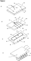
- Figure 2 depicts in an exploded view of the three layers of the embodiment shown in figure 1 .
- Figure 2A shows the upper layer 50 with tubing sockets 51 and aspiration probe guiding 52. Bores for the inlet ports of valves 53 and for the outlet port of valves 54 are also shown.
- Figure 2B shows a top view on the middle layer 60 and figure 2C a bottom view onto the middle layer as shown in figure 1 .
- the middle layer comprises a rinsing solution channel 63, which encloses the aspiration probe guiding 67 so that the part of the aspiration probe (not shown) which is present in the aspiration probe guiding of this layer will get in contact with rinsing solution flowing in the rinsing solution channel from the rinsing solution inlet 61 to the rinsing solution outlet 62.
- Figure 2B shows the cleaning solution channel 64 on top of the middle layer, which is connected to the inlet port of valves 53 of the upper layer 50 (comp. fig. 2A ).
- the sensor bores 65 for arranging sensors directly next to the injector bores 66 are also depicted.
- Figure 2D shows the bottom layer 70 of the embodiment of figure 1 together with cuvettes being arranged directly below injector bores 73 for the injectors.
- This layer comprises sensor bores 72 for measuring liquid flow or flow rates.
- the aspiration probe guiding 71 crosses this layer too.
- Figure 3B shows a top view on the middle layer 60 of the embodiment of figure 1 .
- figure 3A shows on bottom of middle layer 60 the rinsing solution inlet 61, where rinsing solution enters the rinsing solution channel 63 ( fig. 3A ) so that the rinsing solution can flush the aspiration probe that goes through aspiration probe guiding 67.
- the rinsing solution leaves the multilayer unit through rinsing solution outlet 62.
- the embodiment in figure 3B also shows the cleaning solution channel 64, which is arranged below the rinsing solution channel 63.
- Figure 3C depicts in more detail how the rinsing solution flowing in the rinsing solution channel 63 of a middle plate 60 flushes the aspiration probe 30.
- the arrow indicates the flow direction of the rinsing solution and shows that the rinsing solution flows around the aspiration probe30 so that its outer surface will be cleaned.
- Figure 4 shows an upper layer 50 with four valves 80 fixed to it.
- the upper layer 50 is curved and thus adapted for washing probes being arranged in a round carousel for moving cuvettes or reaction vessels.
- valve cables 81 On top of the valves 80 are valve cables 81 arranged for providing power or connection the valves to the automated analyser system for actuating them.
- the aspiration probe guiding 84 goes also through the upper layer 50.
- Glue in sockets 40 are provided to take up supply lines for cleaning or rinsing solution.
- Figure 5 shows a bottom view onto a lower layer 70 with valves 80 being connected via valve cables 81 to the automated analyser system. Cable guiding 83 of the upper layer 50 are also provided.
- the bottom of the lower layer 70 has four injector nozzles 41 for providing cleaning solution to the cuvettes (not shown).
- Figure 6 shows a middle layer 60 connected to an upper layer 50 or more precise an embodiment where upper and middle layer are formed in one part of a multilayer unit.
- Lower layer 70 is not connected to the upper/middle layer 60.
- cable guiding 83 as well as valves 80 with valve cables 81 is shown.
- Rinsing solution channel 63 surrounds the injector nozzles 41.
Landscapes
- Chemical & Material Sciences (AREA)
- Health & Medical Sciences (AREA)
- Analytical Chemistry (AREA)
- General Health & Medical Sciences (AREA)
- Life Sciences & Earth Sciences (AREA)
- Biochemistry (AREA)
- Physics & Mathematics (AREA)
- General Physics & Mathematics (AREA)
- Immunology (AREA)
- Pathology (AREA)
- Clinical Laboratory Science (AREA)
- Chemical Kinetics & Catalysis (AREA)
- Automatic Analysis And Handling Materials Therefor (AREA)
Applications Claiming Priority (1)
| Application Number | Priority Date | Filing Date | Title |
|---|---|---|---|
| GB1616034.3A GB2554352A (en) | 2016-09-26 | 2016-09-26 | Injector manifold |
Publications (1)
| Publication Number | Publication Date |
|---|---|
| EP3299823A1 true EP3299823A1 (fr) | 2018-03-28 |
Family
ID=57288794
Family Applications (1)
| Application Number | Title | Priority Date | Filing Date |
|---|---|---|---|
| EP17192199.2A Withdrawn EP3299823A1 (fr) | 2016-09-26 | 2017-09-20 | Collecteur d'injecteur |
Country Status (3)
| Country | Link |
|---|---|
| US (1) | US11243220B2 (fr) |
| EP (1) | EP3299823A1 (fr) |
| GB (1) | GB2554352A (fr) |
Families Citing this family (1)
| Publication number | Priority date | Publication date | Assignee | Title |
|---|---|---|---|---|
| LU103124B1 (en) * | 2023-05-11 | 2024-11-12 | Stratec Se | Method for the cleaning of fluidic systems |
Citations (6)
| Publication number | Priority date | Publication date | Assignee | Title |
|---|---|---|---|---|
| WO1999004271A1 (fr) * | 1997-07-18 | 1999-01-28 | Sanko Junyaku Co., Ltd. | Appareil de lavage de busettes |
| JP2003156503A (ja) * | 2001-11-20 | 2003-05-30 | Sysmex Corp | 試料分析装置とその装置に用いるピペット洗浄装置 |
| US20080302393A1 (en) * | 2007-05-11 | 2008-12-11 | Bio-Rad Laboratories, Inc. | Wash ring assembly and method of use |
| GB2530340A (en) * | 2014-09-22 | 2016-03-23 | Stratec Biomedical Ag | Liquid injector |
| US20160101423A1 (en) * | 2013-05-01 | 2016-04-14 | Douglas Scientific, LLC | Pipette wash |
| EP3056911A1 (fr) * | 2013-09-12 | 2016-08-17 | Hitachi High-Technologies Corporation | Procédé de nettoyage de buse et analyseur automatisé |
Family Cites Families (9)
| Publication number | Priority date | Publication date | Assignee | Title |
|---|---|---|---|---|
| DE3773562D1 (de) * | 1986-07-11 | 1991-11-14 | Beckman Instruments Inc | Probenhandhabungsvorrichtung. |
| JPH07103986A (ja) * | 1993-09-30 | 1995-04-21 | Kayagaki Irika Kogyo Kk | 検査用ノズルの洗浄方法と検査用稀釈・分注装置 |
| US5897837A (en) * | 1997-02-06 | 1999-04-27 | Toa Medical Electronics Co., Ltd. | Dispensing device and Immunoassay apparatus using the same |
| US6485690B1 (en) * | 1999-05-27 | 2002-11-26 | Orchid Biosciences, Inc. | Multiple fluid sample processor and system |
| AU2001284700B2 (en) * | 2000-08-03 | 2005-12-08 | Caliper Life Sciences, Inc. | Methods and devices for high throughput fluid delivery |
| US7270789B1 (en) * | 2004-03-15 | 2007-09-18 | Astle Thomas W | Pipettor head having standpipes open at their tops to a pressure/vacuum chamber and method |
| US8986614B2 (en) * | 2010-02-23 | 2015-03-24 | Rheonix, Inc. | Self-contained biological assay apparatus, methods, and applications |
| JP4929333B2 (ja) * | 2009-09-30 | 2012-05-09 | 日立オートモティブシステムズ株式会社 | センサの構造 |
| CN203941178U (zh) * | 2011-05-20 | 2014-11-12 | 珀金埃尔默保健科学公司 | 实验室部件和液体装卸系统及辅助性可流动材料装卸系统 |
-
2016
- 2016-09-26 GB GB1616034.3A patent/GB2554352A/en not_active Withdrawn
-
2017
- 2017-09-20 US US15/710,268 patent/US11243220B2/en active Active
- 2017-09-20 EP EP17192199.2A patent/EP3299823A1/fr not_active Withdrawn
Patent Citations (6)
| Publication number | Priority date | Publication date | Assignee | Title |
|---|---|---|---|---|
| WO1999004271A1 (fr) * | 1997-07-18 | 1999-01-28 | Sanko Junyaku Co., Ltd. | Appareil de lavage de busettes |
| JP2003156503A (ja) * | 2001-11-20 | 2003-05-30 | Sysmex Corp | 試料分析装置とその装置に用いるピペット洗浄装置 |
| US20080302393A1 (en) * | 2007-05-11 | 2008-12-11 | Bio-Rad Laboratories, Inc. | Wash ring assembly and method of use |
| US20160101423A1 (en) * | 2013-05-01 | 2016-04-14 | Douglas Scientific, LLC | Pipette wash |
| EP3056911A1 (fr) * | 2013-09-12 | 2016-08-17 | Hitachi High-Technologies Corporation | Procédé de nettoyage de buse et analyseur automatisé |
| GB2530340A (en) * | 2014-09-22 | 2016-03-23 | Stratec Biomedical Ag | Liquid injector |
Also Published As
| Publication number | Publication date |
|---|---|
| GB2554352A (en) | 2018-04-04 |
| GB201616034D0 (en) | 2016-11-02 |
| US11243220B2 (en) | 2022-02-08 |
| US20180080951A1 (en) | 2018-03-22 |
Similar Documents
| Publication | Publication Date | Title |
|---|---|---|
| US8900878B2 (en) | Pipetting device, modular pipetting unit, pipetting system and method for pipetting of fluid samples | |
| US9459186B2 (en) | Sample preparation and loading module | |
| EP1399724B1 (fr) | Systeme et procede pour le traitement automatique de fluide | |
| US20200070167A1 (en) | Processing systems for isolating and enumerating cells or particles | |
| CN101334420B (zh) | 化学分析装置及分析设备 | |
| CN102171551B (zh) | 检体识别分取装置及检体识别分取方法 | |
| US20060245978A1 (en) | Fluid partitioning in multiple microchannels | |
| US9132422B2 (en) | Fluidic interfacing system and assembly | |
| US20070128644A1 (en) | Fluid control method and fluid control apparatus | |
| US10456777B2 (en) | Pressure transmission liquid for cellular analyzer, cellular analyzer and method for analyzing a liquid cellular sample | |
| GB2560014A (en) | Pipetting system | |
| CN111912998A (zh) | 用于化学发光分析仪的液路系统 | |
| EP3732491B1 (fr) | Systeme d'analyse d'echantillon comprenant un agencement de lavage de sonde et son procede d'utilisation | |
| US11243220B2 (en) | Injector manifold | |
| JP4217739B2 (ja) | 再使用のためにマイクロスケールデバイスを処理する方法およびシステム | |
| US20040253821A1 (en) | Method for producing a 3-D microscope flow-through cell | |
| KR20210104091A (ko) | 진단 검출 칩 장치, 그 제조 및 조립 방법 | |
| EP2556887A1 (fr) | Dispositifs microfluidiques améliorés utiles pour l'exposition sélective d'un ou plusieurs échantillons liquides sur une ou plusieurs régions d'échantillon | |
| CN107966522B (zh) | 生物芯片的滴定模块及其滴定测试设备 | |
| GB2530340A (en) | Liquid injector | |
| JPWO2020137226A1 (ja) | 流体計量装置およびそれを有する試料分析装置 | |
| CN210953900U (zh) | 管路堵塞检测件及具有其的样本分析仪 | |
| WO2011012619A1 (fr) | Élément de chargement | |
| CN108828032B (zh) | 一种在线电化学检测装置、方法及电化学免疫分析仪 | |
| TWI650555B (zh) | 微量取樣裝置 |
Legal Events
| Date | Code | Title | Description |
|---|---|---|---|
| PUAI | Public reference made under article 153(3) epc to a published international application that has entered the european phase |
Free format text: ORIGINAL CODE: 0009012 |
|
| STAA | Information on the status of an ep patent application or granted ep patent |
Free format text: STATUS: THE APPLICATION HAS BEEN PUBLISHED |
|
| AK | Designated contracting states |
Kind code of ref document: A1 Designated state(s): AL AT BE BG CH CY CZ DE DK EE ES FI FR GB GR HR HU IE IS IT LI LT LU LV MC MK MT NL NO PL PT RO RS SE SI SK SM TR |
|
| AX | Request for extension of the european patent |
Extension state: BA ME |
|
| STAA | Information on the status of an ep patent application or granted ep patent |
Free format text: STATUS: REQUEST FOR EXAMINATION WAS MADE |
|
| 17P | Request for examination filed |
Effective date: 20180711 |
|
| RBV | Designated contracting states (corrected) |
Designated state(s): AL AT BE BG CH CY CZ DE DK EE ES FI FR GB GR HR HU IE IS IT LI LT LU LV MC MK MT NL NO PL PT RO RS SE SI SK SM TR |
|
| RAP1 | Party data changed (applicant data changed or rights of an application transferred) |
Owner name: STRATEC SE |
|
| STAA | Information on the status of an ep patent application or granted ep patent |
Free format text: STATUS: EXAMINATION IS IN PROGRESS |
|
| 17Q | First examination report despatched |
Effective date: 20210614 |
|
| P01 | Opt-out of the competence of the unified patent court (upc) registered |
Effective date: 20230710 |
|
| STAA | Information on the status of an ep patent application or granted ep patent |
Free format text: STATUS: THE APPLICATION IS DEEMED TO BE WITHDRAWN |
|
| 18D | Application deemed to be withdrawn |
Effective date: 20250114 |