EP3299923B1 - Verfahren zur steuerung der gehhaltung eines zweifüssigen roboters und vorrichtung - Google Patents
Verfahren zur steuerung der gehhaltung eines zweifüssigen roboters und vorrichtung Download PDFInfo
- Publication number
- EP3299923B1 EP3299923B1 EP16869774.6A EP16869774A EP3299923B1 EP 3299923 B1 EP3299923 B1 EP 3299923B1 EP 16869774 A EP16869774 A EP 16869774A EP 3299923 B1 EP3299923 B1 EP 3299923B1
- Authority
- EP
- European Patent Office
- Prior art keywords
- value
- parameter
- phase
- mass
- equal
- Prior art date
- Legal status (The legal status is an assumption and is not a legal conclusion. Google has not performed a legal analysis and makes no representation as to the accuracy of the status listed.)
- Active
Links
Images


Classifications
-
- G—PHYSICS
- G05—CONTROLLING; REGULATING
- G05D—SYSTEMS FOR CONTROLLING OR REGULATING NON-ELECTRIC VARIABLES
- G05D1/00—Control of position, course, altitude or attitude of land, water, air or space vehicles, e.g. using automatic pilots
- G05D1/02—Control of position or course in two dimensions
-
- B—PERFORMING OPERATIONS; TRANSPORTING
- B25—HAND TOOLS; PORTABLE POWER-DRIVEN TOOLS; MANIPULATORS
- B25J—MANIPULATORS; CHAMBERS PROVIDED WITH MANIPULATION DEVICES
- B25J9/00—Program-controlled manipulators
- B25J9/16—Program controls
-
- B—PERFORMING OPERATIONS; TRANSPORTING
- B25—HAND TOOLS; PORTABLE POWER-DRIVEN TOOLS; MANIPULATORS
- B25J—MANIPULATORS; CHAMBERS PROVIDED WITH MANIPULATION DEVICES
- B25J9/00—Program-controlled manipulators
- B25J9/16—Program controls
- B25J9/1656—Program controls characterised by programming, planning systems for manipulators
- B25J9/1664—Program controls characterised by programming, planning systems for manipulators characterised by motion, path, trajectory planning
-
- B—PERFORMING OPERATIONS; TRANSPORTING
- B25—HAND TOOLS; PORTABLE POWER-DRIVEN TOOLS; MANIPULATORS
- B25J—MANIPULATORS; CHAMBERS PROVIDED WITH MANIPULATION DEVICES
- B25J5/00—Manipulators mounted on wheels or on carriages
-
- B—PERFORMING OPERATIONS; TRANSPORTING
- B25—HAND TOOLS; PORTABLE POWER-DRIVEN TOOLS; MANIPULATORS
- B25J—MANIPULATORS; CHAMBERS PROVIDED WITH MANIPULATION DEVICES
- B25J9/00—Program-controlled manipulators
- B25J9/16—Program controls
- B25J9/1602—Program controls characterised by the control system, structure, architecture
-
- B—PERFORMING OPERATIONS; TRANSPORTING
- B62—LAND VEHICLES FOR TRAVELLING OTHERWISE THAN ON RAILS
- B62D—MOTOR VEHICLES; TRAILERS
- B62D57/00—Vehicles characterised by having other propulsion or other ground- engaging means than wheels or endless track, alone or in addition to wheels or endless track
- B62D57/02—Vehicles characterised by having other propulsion or other ground- engaging means than wheels or endless track, alone or in addition to wheels or endless track with ground-engaging propulsion means, e.g. walking members
- B62D57/032—Vehicles characterised by having other propulsion or other ground- engaging means than wheels or endless track, alone or in addition to wheels or endless track with ground-engaging propulsion means, e.g. walking members with alternately or sequentially lifted supporting base and legs; with alternately or sequentially lifted feet or skid
-
- G—PHYSICS
- G05—CONTROLLING; REGULATING
- G05B—CONTROL OR REGULATING SYSTEMS IN GENERAL; FUNCTIONAL ELEMENTS OF SUCH SYSTEMS; MONITORING OR TESTING ARRANGEMENTS FOR SUCH SYSTEMS OR ELEMENTS
- G05B2219/00—Program-control systems
- G05B2219/30—Nc systems
- G05B2219/39—Robotics, robotics to robotics hand
- G05B2219/39208—Robot is active, realizes planned trajectory by itself
Definitions
- the present disclosure relates to the technical field of robot, and particularly to a method and a device for controlling a gait of a biped robot.
- Biped robots are robot systems that simulate the structure and mode of movement of human legs. It has the movement characteristic of human legs, and has complex interaction with the ground during the walking process. Biped robots need high degree of stability controlling when walking. Therefore, reasonable gait controlling is the precondition for realizing the human-simulating steady dynamic walking of biped robots.
- One complete gait of biped robots comprises a step starting phase, a mid-step phase and a step ending phase.
- the step starting phase and the step ending phase are very critical parts of gait controlling, and influence whether the robot can successfully enter the walking state and end the walking state.
- the research on biped robots mainly focuses on the controlling on the gait in the mid-step phase, and the research on the controlling on the gait in the step starting phase and the step ending phase is little. For example,
- US20090271037A1 provides a method of generating a walking pattern for a humanoid robot.
- the method of generating the walking pattern for the humanoid includes determining a position of a next Zero Moment Point (ZMP) along a moving direction of the humanoid robot, obtaining a first condition for generating a walking pattern based on the determined ZMP by using a periodic step module, generating trajectories of a ZMP and a Center of Mass (CoM) in an initial step based on the first condition and an initial value obtained from an initial state of the humanoid robot by using a transient step module, generating trajectories of a ZMP and a CoM in a steady step based on the ZMP of two steps by using a steady step module, and generating trajectories of a ZMP and a CoM in a final step by using the transient step module.
- ZMP Zero Moment Point
- EP1084943A2 provides a robot ambulation control apparatus and a method.
- the apparatus and the method obtain the pattern of movement of the entire body for walking by deriving the pattern of movement of the loins from an arbitrarily selected pattern of movement of the feet, the trajectory of the ZMP, the pattern of movement of the trunk and that of the upper limbs.
- a robot can determine the gait of the lower limbs so as to realize a stable walk regardless if the robot is standing upright or walking.
- ALEXANDER WERNER et al. (“Optimization-based generation and experimental validation of optimal walking trajectories for biped robots ”) studied optimization-based generation and experimental validation of optimal walking trajectories for biped robots, and put forward an efficient formulation, which only requires parameterizing the joint states and does not require to integrate the equations of motion. The results of the optimization are applied to a real robot, with the aid of a suitable stabilizing controller.
- the step starting phase and the step ending phase have poor walking stability, and cannot steadily enter the walking state and steadily end the walking state.
- the present disclosure provides a method and a device for controlling a gait of a biped robot, to solve the problem in the conventional solutions for controlling a gait of a biped robot that the step starting phase and the step ending phase have poor walking stability and cannot steadily enter the walking state and steadily end the walking state.
- a device for controlling a gait of a biped robot according to claim 10.
- the advantageous effects of the present disclosure are: the solution of controlling a gait of a biped robot of the embodiments of the present disclosure firstly selects gait controlling parameters of the biped robot, acquires a movement trajectory of a center of mass in the mid-step phase when a zero moment point ZMP of the biped robot is located within a steady area and first numerical values and second numerical values that are corresponding to each of the gait controlling parameters, determines the movement trajectory of the center of mass in the step starting phase according to the first numerical values, and calculates the movement trajectory of the center of mass in the step ending phase by using the second numerical values, thereby realizing keeping the continuous linking of the step starting phase and the step ending phase with the mid-step phase by the gait controlling parameters.
- each of the phases satisfies the steady walking condition, which ensures the steady walking of the biped robot in the whole movement.
- the technical solutions on the basis of ensuring that the center of mass of the robot satisfies steady walking, provide on the basis of the movement trajectory of the center of mass a new solution of controlling the walking gaits of each of the joints of the legs, and such a controlling solution can further improve the stability of the walking process, increase the efficiency of the whole walking process, and realize the steady starting and ending of the walking process.
- the technical solutions of the embodiments of the present disclosure propose solutions of controlling the complete gait of the steady walking of a biped robot, which can more effectively realize steady step starting and steady step ending.
- the technical solutions by obtaining the movement trajectory in the mid-step phase on the precondition that the zero moment point is always located in the steady area, reasonably link the movement trajectories of the step starting phase, the step ending phase and the mid-step phase in terms of position, speed and/or acceleration, to ensure that the step starting phase and the step ending phase can both satisfy the stability condition.
- the solutions by using the conversion between potential energy and kinetic energy when the robot is moving, can start and end the normal walking process rapidly in one step, which avoids the problem in the prior art that several phases are required to reach and end the normal walking state, and realizes the steady and fast walking of the biped robot.
- Fig. 1 is the schematic flow chart of a method for controlling a gait of a biped robot according to an embodiment of the present disclosure.
- the method for controlling a gait of a biped robot comprises the following steps:
- the gait controlling parameters comprise three parameters of position, speed and acceleration, or the gait controlling parameters comprise two parameters of position and speed. Further, each parameter of the gait controlling parameters comprises three direction components of a forward direction, a lateral direction and a vertical direction when the biped robot is walking.
- the method for controlling a gait of a biped robot of the present embodiment controls both the movement trajectories of the center of mass of the biped robot in the step starting phase and the step ending phase, and by the controlling, when the biped robot is walking, the movement trajectory of the center of mass satisfies each of the movement trajectories of the center of mass in the step starting phase, the mid-step phase and the step ending phase, to realize a steady walking of the biped robot.
- the stability can also be ensured by controlling the movement trajectories of the center of mass in the step starting phase and the step ending phase by using the corresponding numerical values of the gait controlling parameters that are determined by the movement trajectory of the center of mass in the mid-step phase. That is, compared with the prior art, the method of the present embodiment can ensure the stability in the step starting phase and the step ending phase, and meanwhile achieves better linkings between the step starting phase and the mid-step phase and between the mid-step phase and the step ending phase, which realizes that the biped robot can steadily walk throughout a complete walking process.
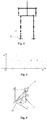
- Fig. 2 is the forward direction view of a nine-link model of a biped robot according to an embodiment of the present disclosure.
- Fig. 3 is the lateral direction view of a nine-link model of a biped robot according to an embodiment of the present disclosure.
- Fig. 4 is the projection schematic representation of the walking position of a biped robot according to an embodiment of the present disclosure.
- P1-P9 individually represent different parts of the biped robot; for example, P8 and P9 represent the left arm and the right arm of the biped robot, and m1-m7 individually represent the masses of the links.
- a Cartesian coordinate system is constructed. As shown in Fig. 2 and Fig.
- FIG. 3 they show the forward direction view (that is, the xoz plane) and the lateral direction view (that is, the yoz plane) of a simplified model of the biped robot that is constructed by nine homogeneous-material links and joints, in which a single shoulder joint of the biped robot has one degree of freedom of front-and-back swinging, a single ankle joint has two degrees of freedom of front-and-back swinging and left-and-right swinging, a single knee joint has one degree of freedom of front-and-back swinging, and a hip joint has three degrees of freedom of left-and-right swinging, front-and-back swinging and rotation.
- a single shoulder joint of the biped robot has one degree of freedom of front-and-back swinging
- a single ankle joint has two degrees of freedom of front-and-back swinging and left-and-right swinging
- a single knee joint has one degree of freedom of front-and-back swinging
- a hip joint has three degrees of freedom of left-and-right swing
- the planar rectangular coordinate system (XOY) of the biped robot itself is constructed.
- the center of mass of the biped robot has a new supporting point.
- the planar rectangular coordinate system (XOY) of the biped robot itself is constructed.
- the terminating state of the previous supporting point is taken as the initial state, so that the robot starts again a new single step, and by linking those single steps the continuous walking mode of the robot is constructed. As shown in Fig.
- the projection on the ground of the ankle joint of the right supporting leg is taken as the origin of coordinate (that is, the point O represents the projection in the planar rectangular coordinate system of the right leg of the biped robot, and the point that has a predetermined distance from the point O in the Y-axis direction represents the projection in the planar rectangular coordinate system of the left leg of the biped robot).
- the points in the X-axis represent the movement trajectory of the right supporting leg when the biped robot is walking, and the points that are on the left of the X-axis and have a predetermined distance from the X-axis represent the movement trajectory of the left supporting leg.
- the method is illustratively described by taking the example that the gait controlling parameters are position, speed and acceleration.
- a solution of controlling a gait of a biped robot must be evaluated in terms of stability, and the present embodiment takes zero moment point (for short, ZMP) as an important base of the stability of the dynamic walking of the biped robot.
- ZMP is the point of action of the accumulated force exerted on the sole of the supporting leg of the robot, and at that point the moment of the accumulated force is zero in the horizontal direction.
- the steady area refers to the projection on the horizontal plane of the convex-shaped area that is formed by the supporting foot.
- the mid-step phase is the phase of the smooth periodic walking of the biped robot.
- a complete single step consists of a one-leg-supporting period (the duration is set as T 1 ) and a two-leg-supporting period (the duration is set as T 2 ), and the whole mid-step phase has a plurality of one-leg-supporting periods and two-leg-supporting periods that appear periodically.
- the present embodiment in both the one-leg-supporting periods and the two-leg-supporting periods, employs a linear inverted pendulum model to control the trajectory of the center of mass, to ensure that the walking of the robot satisfies the stability condition (that is, the zero moment point ZMP is always located within the steady area).
- the present disclosure is not limited to the linear inverted pendulum model, and other models can be employed to calculate the movement trajectory of the center of mass.
- the method after acquiring the movement trajectory of the center of mass of the biped robot in the mid-step phase, by using the movement trajectory, obtains the numerical values of each of the gait controlling parameters of the center of mass when the mid-step phase starts as first numerical values, and obtains the numerical values of each of the gait controlling parameters of the center of mass when the mid-step phase ends as second numerical values.
- the method is to obtain the following information of the biped robot: when the mid-step phase starts, the position X d (0), speed ⁇ d (0) and acceleration ⁇ d (0) in the x-axis direction and the position Y d (0), speed ⁇ d (0) and acceleration ⁇ d (0) in the y-axis direction of the coordinate system of the center of mass; and when the mid-step phase ends, the position X s (0), speed ⁇ s (0) and acceleration ⁇ s (0) in the x-axis direction and the position Y s (0), speed ⁇ s (0) and acceleration ⁇ s (0) in the y-axis direction of the coordinate system of the center of mass.
- the walking stability is to be kept throughout the whole mid-step phase, it is set that the height of the center of mass of the biped robot is not changed, that is, the position of the center of mass in the z-axis direction is not changed, and the speed and the acceleration are both equal to 0, so the movement trajectory in the Z-axis direction can be known in advance.
- the height of the center of mass changes in the mid-step phase it is required to acquire the heights of the center of mass when the mid-step phase starts and when the mid-step phase ends (that is, the special numerical values in the z-axis direction).
- the above first numerical values and second numerical values are acquired from the calculation results of the linear inverted pendulum model.
- the constructing of the linear inverted pendulum model and the calculating by using the linear inverted pendulum model are not the key of the embodiments of the present disclosure, and can be implemented by using the prior art, and the detailed calculating method will not be in detail described and will only be described briefly as follows.
- the method simplifies the robot in the two-leg-supporting periods as a virtual linear inverted pendulum model.
- Fig. 5 is the schematic representation of the principle of the linear inverted pendulum model that the present embodiment employs. As shown in Fig.
- the model takes the ZMP of the movement of the robot as a virtual supporting point and the center of mass 51 of the robot as the mass point of the linear inverted pendulum model
- the supporting foot 52 and the supporting foot 53 are the two supporting feet of the robot in the two-leg-supporting periods
- the ZMP is the virtual supporting point of the inverted pendulum and is located between the two supporting feet.
- the characteristic of the inverted pendulum model is that the height of the center of mass remains unchanged, and the bottom end of the swinging rod does not provide moment of force. That is, in the mid-step phase, the height of the center of mass of the biped robot in the vertical direction is not changed and is a predetermined value Hz .
- the present embodiment firstly designs the movement trajectory of the ZMP in the two-leg-supporting period, and then solves the movement trajectory of the center of mass.
- Such a solution can not only ensure that the ZMP smoothly moves from the previous supporting foot to the subsequent supporting foot, but also can ensure the continuity of the change of the speed of the center of mass, thereby enhancing the stability of the walking movement of the robot.
- the positions x ZMP and y ZMP of the ZMP are required to be in advance reasonably designed within the supporting area that is formed by the two feet of the robot, so that they can smoothly move within the supporting area.
- the a constraint relation of the boundary condition between the two-leg-supporting period and the one-leg-supporting period is well handled, that is, the boundaries between Formulas (1), (2) and Formulas (3),(4) maintain continuous, to ensure that they can smoothly transit.
- the method can solve the trajectory of the center of mass in the x-axis direction and the y-axis direction at the starting time moment in the two-leg-supporting period in the mid-step phase, and can solve first numerical values X d (0), ⁇ d (0), ⁇ d (0), Y d (0), ⁇ d (0) and ⁇ d (0) respectively corresponding to each of the gait controlling parameters, namely position, speed and acceleration, at the starting time moment in the two-leg-supporting period and can solve second numerical values X s (0), ⁇ s (0), ⁇ s (0), Y s (0), ⁇ s (0) and ⁇ s (0) respectively corresponding to each of the gait controlling parameters, namely position, speed and acceleration, at the starting time moment in the one-leg-supporting period and then uses the acquired first numerical values and the second numerical values for the controlling of the movement trajectory of the center of mass in the step starting phase and the step ending
- the step starting phase is the transition phase between the static standing state when the two feet of the robot are parallel and close and the mid-step gait that has a steady periodicity.
- the duration of this phase is set as T 1 .
- a first constraint condition that the center of mass satisfies when the step starting phase ends comprises: a first forward direction constraint condition (that is, the constraint condition in the x-axis direction), a first lateral direction constraint condition (that is, the constraint condition in the y-axis direction) and a first vertical direction constraint condition (that is, the constraint condition in the z-axis direction).
- the embodiment of the present disclosure converts potential energy into kinetic energy as far as possible by lowering the center of gravity of the robot, so that the robot can enter the mid-step phase faster (that is, realizing the advantageous effect of starting in one step).
- the method calculate a height Hz of the center of mass in the vertical direction of the biped robot when the step starting phase ends.
- the method firstly estimates by the following Formula (5) the approximate distance ⁇ z by which the center of gravity is to descend.
- m ⁇ g ⁇ ⁇ ⁇ z 1 2 m v 1 2 ⁇ v 0 2
- the initial speed v 0 0 of the center of mass in the step starting phase
- v 1 is the final speed of the center of mass in the step starting phase
- m is the mass of the robot
- g gravitational acceleration.
- the height of the center of mass is required to be maintained unchanged, that is, equal to the height Hz of the center of mass at the ending time moment in the step starting phase.
- the first vertical direction constraint condition of the center of mass comprises: when the step starting phase starts, the value of the position parameter is equal to the initial height of the center of mass of the biped robot, the value of the speed parameter is equal to 0, and the value of the acceleration parameter is equal to 0; and when the step starting phase ends, the value of the position parameter is equal to the height Hz of the center of mass in the vertical direction when the step starting phase ends, the value of the speed parameter is equal to 0, and the value of the acceleration parameter is equal to 0.
- the height Hz of the center of mass at the ending time moment in the step starting phase can be determined from a difference value between the initial height Hz 0 of the center of mass and a descending distance ⁇ z , and can also be a value whose difference from the difference value is no greater than a predetermined value. That is, the specific numerical value of the Hz can be equal to the difference value that is obtained by subtracting the ⁇ z from the Hz 0 , and can also be equal to a value that is near the difference value, which is not limited, provided that a preferred value can be acquired to ensure the stability of the walking. It can be understood that, the first numerical value of each of the gait controlling parameters can take other numerical values that are near the numerical value on the right side of each of the equations in Formula (6) and do not have too large deviations.
- the first forward direction constraint condition that the center of mass satisfies comprises: when the step starting phase starts, the value of the position parameter, the value of the speed parameter and the value of the acceleration parameter are all equal to 0; and when the step starting phase ends, the value of the position parameter is equal to a first position parameter forward direction numerical value, the value of the speed parameter is equal to a first speed parameter forward direction numerical value, and the value of the acceleration parameter is equal to a first acceleration parameter forward direction numerical value. That is, the position, speed and acceleration of the center of mass at the initial time moment are all equal to 0.
- the embodiment of the present disclosure sets that the position, speed and acceleration at the ending time moment in the step starting phase are the same as the initial position, speed and acceleration in the two-leg-supporting period in the mid-step phase, to ensure the smooth transition between the gait in the step starting phase and the gait of the mid-step phase.
- the distance between the two feet of the robot is set as W.
- the first lateral direction constraint condition that the center of mass satisfies comprises: when the step starting phase starts, the value of the position parameter is equal to a half of a distance between the two feet of the biped robot, the value of the speed parameter is equal to 0, and the value of the acceleration parameter is equal to 0; and when the step starting phase ends, the value of the position parameter is equal to a first position parameter lateral direction numerical value, the value of the speed parameter is equal to a first speed parameter lateral direction numerical value, and the value of the acceleration parameter is equal to a first acceleration parameter lateral direction numerical value.
- the center of mass is in an intermediate position of the distance between the two feet, and the speed and the acceleration are both equal to 0.
- the center of mass is farthest deviated from the supporting point, and the embodiment of the present disclosure sets that the position, speed and acceleration in the y-axis direction at this time are the same as the position, speed and acceleration when the two-leg-supporting period in the mid-step phase starts, to ensure their smooth transition, and to ensure that the step starting phase also satisfies the stability condition.
- the step ending phase refers to the process during which the robot, from the mid-step gait that has a steady periodicity, gradually reduces the speed, till the robot returns the steady static standing state.
- the duration of the phase is set as T 1 .
- the second constraint condition that the center of mass is required to satisfy comprises: a second forward direction constraint condition (that is, the constraint condition in the x-axis direction), a second lateral direction constraint condition (that is, the constraint condition in the y-axis direction) and a second vertical direction constraint condition (that is, the constraint condition in the z-axis direction).
- the second vertical direction constraint condition of the center of mass comprises: when the step ending phase starts, the value of the position parameter is equal to the height Hz in the vertical direction when the step starting phase ends, the value of the speed parameter is equal to 0, and the value of the acceleration parameter is equal to 0; and when the step ending phase ends, the value of the position parameter is equal to the initial height of the center of mass of the biped robot, the value of the speed parameter is equal to 0, and the value of the acceleration parameter is equal to 0.
- the embodiment of the present disclosure by lifting the center of gravity of the robot, that is, lifting from the height Hz of the center of mass in the mid-step phase to the height Hz 0 when the step starting phase starts, converts kinetic energy into potential energy as far as possible, so that the robot enters the steady static state faster (that is, realizing the advantageous effect of ending steps in one step).
- the embodiment of the present disclosure sets that the position, speed and acceleration at the initial time moment in the step ending phase are the same as the position, speed and acceleration of the center of mass at the ending time moment (that is, when the one-leg-supporting period starts) in the mid-step phase.
- the second numerical value of each of the gait controlling parameters can take other numerical values that are near the numerical value on the right side of each of the equations in Formula (12) and do not have too large deviations, and are not limited to the numerical values that are exemplified on the right side of each of the equations in Formula (12).
- the second forward direction constraint condition of the center of mass comprises: when the step ending phase starts, the value of the position parameter is equal to a second position parameter forward direction numerical value, the value of the speed parameter is equal to a second speed parameter forward direction numerical value, and the value of the acceleration parameter is equal to a second acceleration parameter forward direction numerical value; and when the step ending phase ends, the value of the position parameter, the value of the speed parameter and the value of the acceleration parameter are all equal to 0.
- the embodiment of the present disclosure sets that the position, speed and acceleration of the center of mass at the initial time moment in the step ending phase are respectively the same as the position, speed and acceleration at the ending time moment in the two-leg-supporting period in the mid-step phase, and according to symmetry and continuity, that is, they are respectively the same as the position, speed and acceleration at the starting time moment in the one-leg-supporting period in the mid-step phase, to ensure their smooth transition, and to ensure that the step ending phase also satisfies the stability condition.
- the position, speed and acceleration of the center of mass at the ending time moment in the step ending phase are all equal to 0, to return the steady static standing state.
- the position X ( T 1 ) of the center of mass is equal to 0
- the speed ⁇ ( T 1 ) is equal to 0 and
- the second lateral direction constraint condition of the center of mass comprises: when the step ending phase starts, the value of the position parameter is equal to a second position parameter lateral direction numerical value, the value of the speed parameter is equal to a second speed parameter lateral direction numerical value, and the value of the acceleration parameter is equal to a second acceleration parameter lateral direction numerical value; and when the step ending phase ends, the value of the position parameter is equal to a half of a distance between the two feet of the biped robot, and the value of the speed parameter and the value of the acceleration parameter are both equal to 0.
- the present embodiment sets that the position, speed and acceleration of the center of mass at the starting time moment in the step ending phase are respectively the same as the position, speed and acceleration at the ending time moment in the two-leg-supporting period in the mid-step phase, and according to symmetry and continuity, that is, they are respectively the same as the position, speed and acceleration at the starting time moment in the one-leg-supporting period in the mid-step phase, to ensure their smooth transition, and to ensure that the step ending phase also satisfies the stability condition.
- the center of mass is located in the intermediate position of the distance between the two feet, and the speed and the acceleration are both equal to 0, to return the steady static standing state.
- the method is illustratively described by taking the example that the gait controlling parameters comprise position, speed and acceleration; however, in other embodiments of the present disclosure, the gait controlling parameters can comprise position and speed, and when the gait controlling parameters are position and speed, the position parameter and the speed parameter both comprise three direction components of a forward direction, a lateral direction and a vertical direction when the biped robot is walking.
- the gait controlling parameters can comprise position and speed
- the position parameter and the speed parameter both comprise three direction components of a forward direction, a lateral direction and a vertical direction when the biped robot is walking.
- the method further comprises: calculating, according to an expected movement height of ankle joints of the biped robot, the movement trajectories of the ankle joints of the two legs in the step starting phase, the mid-step phase and the step ending phase; by using the movement trajectories of the ankle joints, calculating the expected angular trajectories of the ankle joints in each of the phases; according to the structural position relations between the center of mass, the knee joints and the ankle joints of the biped robot in each of the phases and the movement trajectories of the center of mass and the ankle joints in each of the phases in walking, obtaining the movement trajectories of the knee joints in each of the phases by calculating; and by using the movement trajectories of the knee joints in the step starting phase, the mid-step phase and the step ending phase, calculating the expected angular trajecto
- the ankle joint of the swinging leg must pass through three key points, namely, a starting point, a highest point and a terminating point.
- the method can solve the movement trajectory of the ankle joint of the swinging leg by using polynomial interpolation.
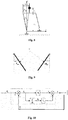
- Fig. 6 is the forward direction schematic representation of the supporting leg of a biped robot according to an embodiment of the present disclosure.
- Fig. 7 is the forward direction schematic representation of the swinging leg of a biped robot according to an embodiment of the present disclosure.
- L c represents the distance between the center of mass of the biped robot and the hip joint
- L k represents the distance between the hip joint and the knee joint
- L a represents the distance between the knee joint and the ankle joint
- the H h in Fig. 6 and the H h 1 in Fig. 7 represent the distance between the hip joint and the ankle joint.
- the method obtains the joint angles of the supporting leg: a joint angle ⁇ a of the ankle joint, a joint angle ⁇ k of the knee joint and a joint angle ⁇ h of the hip joint, and the trajectories of the varying with time of the angles.
- the ⁇ (that is, the angle between the connecting line connecting a hip joint and an ankle joint and the y-axis), ⁇ a , ⁇ h , ⁇ k and ⁇ a1 , ⁇ h1 , ⁇ k1 in Fig. 6 and Fig. 7 are calculation-assisting angles that are used in the intermediate calculating processes.
- Fig. 8 is the lateral direction schematic representation of the two legs of a biped robot according to an embodiment of the present disclosure.
- the center of mass in the lateral direction plane (that is, the projection of the robot in the yoz plane in moving), is at a half of the distance between the two feet of the biped robot W/2, the distance between the center of mass and the hip joint is z ch , the distance between the hip joint and the ankle joint is z ce , and the y-coordinate of the hip joint relative to the supporting foot is y ce .
- the upper part of the body should be kept vertical and the soles should be kept horizontal, so the above walking in a plane can be simplified as an issue of one degree of freedom.
- the angles that are relevant to the gaits are the rotational freedom (turning around the x-axis) of the ankle joints and the rotational freedom of the hip joints.
- the two ankle joints have the same angles and directions, and the two hip joints have the same angles themselves and the opposite directions to the ankle joints.
- the method can obtain the joint angles of the swinging leg: a joint angle ⁇ a1 of the ankle joint, a joint angle ⁇ k1 of the knee joint and a joint angle ⁇ h1 of the hip joint, and the trajectories of the varying with time of the angles.
- the angles ⁇ and ⁇ ce in Fig. 8 are the left and right angles between the connecting line connecting a hip joint and an ankle joint and the vertical direction when the robot is walking, and are calculation-assisting angles.
- the calculating process of calculating, according to an expected movement height of the ankle joint of the biped robot, the movement trajectory of the ankle joint in the step starting phase, the mid-step phase and the step ending phase is: presetting the expected movement height of the ankle joint (for example, H h ), wherein the height is the highest point of the moving of the ankle joint, and the position, speed and acceleration of the starting point of the ankle joint are all equal to 0, the position, speed and acceleration of the terminating point are all equal to 0, and the position of the highest point is H h and its speed and acceleration are equal to 0; calculating according to those numerical values the constraint condition that the ankle joint satisfies; and according to the constraint condition, by using polynomial interpolation, obtaining the movement trajectory of the ankle joint from the starting point to the highest point and the movement trajectory from the highest point to the terminating point by calculating.
- H h expected movement height of the ankle joint
- the method further comprises, according to the movement trajectories of the center of mass and the ankle joint in each of the phases in walking, obtaining the spatial positions where the center of mass and the ankle joint locate at each of the time moments; according to the geometric position relation of the center of mass and the hip joint of the robot, obtaining the spatial position of the hip joint; according to the structural position relations between the hip joint, the knee joint and the ankle joint of the biped robot, referring to structural parameters such as the lengths of the thighs and the shanks and by using triangular geometrical relations, calculating and obtaining the position and angle of the knee joint, further obtaining the movement trajectories of the knee joint in the step starting phase, the mid-step phase and the step ending phase, and meanwhile obtaining the expected angular trajectories of the knee joint in each of the phases.
- the joint angles of the ankle joint, the knee joint and the hip joint of the leg of the biped robot are calculated by triangular geometrical relations, but in other embodiments of the present disclosure the above calculating process can also be completed by using other calculating methods, provided that the methods can calculate the expected angles of the leg joints and the hip joints of the biped robot.
- Other calculating methods comprise, for example, inverse kinematics analysis. Inverse kinematics is solving corresponding joint variables according to known location and position of an end actuator.
- the prior art provides various calculating solutions (for example, analytic method, geometric method, geometric analytic method and numerical method), and the prior art solutions can realize obtaining the expected angular trajectory of the hip joint (that is, the trajectory that varies with time of the joint angle of the hip joint) according to the movement trajectory of the hip joint.
- the embodiment of the present disclosure exerts no limit to the inverse kinematics analysis methods.
- how to solve the expected angular trajectory is not the keynote of the embodiment of the present disclosure, and the specific implementation can employ any solution of inverse kinematics analysis, which will not be in detail described here.
- the present embodiment calculates the movement trajectory of the center of mass and the respective movement trajectory of the hip joint and the ankle joint by using polynomial interpolation, but in the technical solutions of the present disclosure the calculating of the movement trajectories of the center of mass, the hip joint and the ankle joint is not limited to polynomial interpolation as in the present embodiment. Other calculating methods that can be implemented can also be employed.
- the method after obtaining the expected angular trajectories of the ankle joints, the knee joints and the hip joints of the two legs of the biped robot by calculating, selects one or more of the hip joints, the ankle joints and the knee joints as a controlling point; when the biped robot is walking, detects in real time the turning angle of the controlling point (for example the ankle joint, the knee joint and the hip joint), and performs self-adaptive tracking controlling on the detected turning angles of the hip joints and the ankle joints by using the expected angular trajectories of the ankle joints, the knee joints and the hip joints in each of the phases respectively, to realize a steady walking of the biped robot.
- the controlling point for example the ankle joint, the knee joint and the hip joint
- Fig. 10 is the schematic representation of a structure for controlling the angles of the joints of a biped robot according to an embodiment of the present disclosure.
- ⁇ d is the expected joint angle
- ⁇ r is the joint angle that is actually detected
- k p is a proportionality factor
- k d is a differential coefficient
- ⁇ is the moment of rotation.
- the method is illustratively described by taking the example of the hip joints.
- the method after obtaining the expected angles of the hip joints in each of the phases of the walking of the robot, by using moment of force controlling, by directly taking the detected turning angles of the hip joints as the feedback, obtains the difference between that feedback and the joint turning angles (the expected angles) that are required by the gaits in each of the above phases, controls by using a proportion integration differentiation PID controller or a proportion differentiation PD controller, and outputs the input torque of the hip joints of the biped robot, to thereby drive the movement of the hip joints of the robot, to achieve the aim of steady walking.
- the solution of the embodiment of the present disclosure simplifies the nonlinear coupling system of the biped robot into a linear multivariable decoupling system by moment of force controlling.
- each of the joints of the biped robot can be controlled by an individual PID or PD controller, to realize the follow-up controlling on the expected angles of each of the joints, to finally realize the steady operation of the robot following the preset gaits.
- the two arms of the robot are required to cooperate with the legs by front-and-back swinging, and the swinging is required to be symmetrical to the alternate swinging of the two legs.
- the gait controlling method further comprises: selecting angle controlling parameters of swingings of shoulder joints of the biped robot: angular displacement, angular speed and angular acceleration; according to angular displacement values, angular speed values and angular acceleration values that a shoulder joint corresponding to the swinging leg is expected to reach at a starting time moment and an terminating time moment of the swinging of a swinging leg of the biped robot in the mid-step phase respectively, setting an angular constraint condition that the shoulder joint corresponding to the swinging leg is required to satisfy; according to the angular constraint condition and by using polynomial interpolation, calculating expected angular trajectory of the swinging of the shoulder joint in the mid-step phase; by using an angular displacement value, an angular speed value and an angular acceleration value that a shoulder joint corresponding to the swinging leg is expected to reach at a starting time moment of the swinging of a swinging leg of the biped robot in the mid-step phase, and, setting a first angular constraint
- Fig. 9 is the schematic representation of the swinging angles of the shoulder joints of a biped robot according to an embodiment of the present disclosure.
- T T 1 + T 2 of the mid-step phase
- the right shoulder joint 91 reaches the maximum value and the minimum value of the swinging angle respectively at the starting time moment and the terminating time moment of the single step period
- ⁇ (0) is the angular displacement of the swinging of the right shoulder joint at the starting time moment in the single step period in the mid-step phase
- ⁇ (0) represents the angular speed
- ⁇ (0) represents the angular acceleration
- ⁇ ( T ) is the angular displacement of the swing
- angles of the swinging of the left shoulder joint are symmetrical with those in the front-and-back direction.
- the initial values of the swinging angles of the shoulder joints are equal to 0, and regarding the step ending phase, the end values of the swinging angles of the shoulder joints are equal to 0; further, they are required to link with the swinging angles in the mid-step gait.
- the method after obtaining the first angular constraint condition and the second angular constraint condition, similarly can obtain the expected angular trajectories of the swinging angles of the shoulder joints in the step starting phase and the step ending phase.
- angles of the swinging of the left shoulder joint are symmetrical with those in the front-and-back direction.
- the specific calculating process can be seen in the above description on the trajectory of the angle in the single step period in the mid-step phase, and will not be in detail described here.
- the embodiments of the present disclosure after the biped robot enters the mid-step gait, control the position of the center of mass of the robot by using the linear inverted pendulum model (that is, solves the first numerical values and the second numerical values of each of the gait controlling parameters), to increase the walking stability and prevent the instability and the impact on the robot that are caused by the instant switching of the supporting leg in the mid-step phase of the periodical walking.
- the embodiments of the present disclosure by using polynomial interpolation, determine the first constraint condition that the center of mass satisfies in the step starting phase and the second constraint condition that the center of mass satisfies in the step ending phase respectively according to the first numerical values and the second numerical values corresponding to each of the gait controlling parameters, thereby controlling both the moving trajectories of the center of mass of the biped robot in the step starting phase and the step ending phase, and controlling the walking of the biped robot, so that when the biped robot is walking the movement trajectory of the center of mass satisfies each of the movement trajectories of the center of mass in the step starting phase, the mid-step phase and the step ending phase, to realize a steady walking of the biped robot.
- the solutions by using the kinetic energy that is converted from the potential energy of the robot, realize entering the normal mid-step walking state in one step in the step starting phase, and, by converting kinetic energy into potential energy, complete the step ending process in one step in the step ending phase, and cause the step starting phase and the step ending phase to continuously link with the mid-step gait, to satisfy the steady walking condition, and to realize the high-efficiency and steady starting and ending of the walking process.
- the solutions after obtaining the trajectories of the center of mass in the step starting phase, the mid-step phase and the step ending phase, calculate the joint turning angles of the hip joints, the knee joints and the ankle joints of the two legs by the structural features of the robot and inverse kinematics analysis. Finally, the solutions, by the controlling on each of the joint turning angles of the biped robot, further ensure the stability of the center of mass in walking, and realize the walking stability of the biped robot.
- a device for controlling a gait of a biped robot comprising: a center of mass mid-step phase trajectory acquiring unit, for selecting gait controlling parameters of the biped robot in a step starting phase, a mid-step phase and a step ending phase, and acquiring a movement trajectory of a center of mass of the biped robot in the mid-step phase when a zero moment point of the biped robot is located within a steady area; a parameter value acquiring unit, for obtaining, according to the movement trajectory of the center of mass in the mid-step phase, first numerical values of each of the gait controlling parameters of the center of mass when the mid-step phase starts and second numerical values of each of the gait controlling parameters of the center of mass when the mid-step phase ends; a constraint condition setting unit, for setting a first constraint condition that the center of mass is required to satisfy when the step starting phase ends by using the first numerical values, and setting a second constraint condition that the center of mass is required to satisfy when the
- the center of mass trajectory controlling unit comprises: an ankle joint trajectory calculating unit, a hip joint trajectory calculating unit, a joint angle calculating unit and a joint angle controlling unit;
- the ankle joint trajectory calculating unit is for calculating, according to an expected movement height of ankle joints of the biped robot, the movement trajectories of the ankle joints of the two legs in the step starting phase, the mid-step phase and the step ending phase;
- the hip joint trajectory calculating unit is for calculating, according to the movement trajectories of the center of mass in each of the phases, the movement trajectories of hip joints of the biped robot in the step starting phase, the mid-step phase and the step ending phase;
- the joint angle calculating unit is for, by using the movement trajectories of the hip joints and the ankle joints in each of the phases, the structural position relations of the legs of the biped robot and a leg length numerical value, obtaining expected angular trajectories of the hip joints, the ankle joints and knee joints in each of the phases by calculating;
- each parameter of the gait controlling parameters comprises three direction components of a forward direction, a lateral direction and a vertical direction when the biped robot is walking; wherein, the gait controlling parameters comprise position and speed, or the gait controlling parameters comprise position, speed and acceleration.
- the center of mass mid-step phase trajectory acquiring unit is specifically for that each parameter of the acquired gait controlling parameters comprises three direction components of a forward direction, a lateral direction and a vertical direction when the biped robot is walking; wherein, the gait controlling parameters comprise position and speed, or the gait controlling parameters comprise position, speed and acceleration.
- the center of mass step starting and step ending phase trajectory calculating unit is further for, according to an initial speed of the center of mass when the mid-step phase starts that is expected to reach and a conversion relation between kinetic energy and potential energy, calculating a height Hz of the center of mass in the vertical direction of the biped robot when the step starting phase ends;
- the movement trajectory of the center of mass of the biped robot in the mid-step phase acquired by the center of mass mid-step phase trajectory acquiring unit satisfies the following condition: the heights of the center of mass in the vertical direction when the mid-step phase starts and when the mid-step phase ends are both Hz.
- the parameter value acquiring module is further for selecting angle controlling parameters of swingings of shoulder joints of the biped robot: angular displacement, angular speed and angular acceleration;
- the constraint condition setting unit is further for, according to angular displacement values, angular speed values and angular acceleration values that a shoulder joint corresponding to the swinging leg is expected to reach at a starting time moment and an terminating time moment of the swinging of a swinging leg of the biped robot in the mid-step phase, setting an angular constraint condition that the shoulder joint corresponding to the swinging leg is required to satisfy;
- the center of mass step starting and step ending phase trajectory calculating unit is further for, according to the angular constraint condition and by using polynomial interpolation, calculating expected angular trajectory of the swinging of the shoulder joint in the mid-step phase;
- the constraint condition setting unit is further for, by using an angular displacement value, an angular speed value and an angular acceleration value that a shoulder joint corresponding to the swinging
- the position parameter and the speed parameter both comprise three direction components of a forward direction, a lateral direction and a vertical direction when the biped robot is walking;
- the first constraint condition that the center of mass satisfies when the step starting phase ends comprises: a first forward direction constraint condition, a first lateral direction constraint condition and a first vertical direction constraint condition;
- the first forward direction constraint condition comprises: when the step starting phase starts, the value of the position parameter and the value of the speed parameter are both equal to 0; and when the step starting phase ends, the value of the position parameter is equal to a first position parameter forward direction numerical value, and the value of the speed parameter is equal to a first speed parameter forward direction numerical value;
- the first lateral direction constraint condition comprises: when the step starting phase starts, the value of the position parameter is equal to a half of a distance between the two feet of the biped robot, and the value of the speed parameter is
- the device for controlling a gait of a biped robot of the present embodiment is corresponding to the above method for controlling a gait of a biped robot. Therefore, the working process of the gait controlling device of the present embodiment can be seen in the corresponding descriptions of the above method, and will not be in detail described here.
- the embodiments of the present disclosure propose a method for controlling the step starting phase and the step ending phase that is more effective, can start and end the normal walking process rapidly in one step, which avoids the problem in the prior art that several phases are required to reach and end the normal walking state.
- the step starting phase and the step ending phase are both also ensured to satisfy the stability condition.
- the embodiments of the present disclosure by designing by the linear inverted pendulum model in the one-leg-supporting period and the two-leg-supporting period, ensure that the robot satisfies the stability condition in the two phases, and reduce the impact on the robot during the switching of the supporting leg.
Landscapes
- Engineering & Computer Science (AREA)
- Mechanical Engineering (AREA)
- Robotics (AREA)
- Chemical & Material Sciences (AREA)
- Combustion & Propulsion (AREA)
- Transportation (AREA)
- Automation & Control Theory (AREA)
- Physics & Mathematics (AREA)
- General Physics & Mathematics (AREA)
- Radar, Positioning & Navigation (AREA)
- Remote Sensing (AREA)
- Aviation & Aerospace Engineering (AREA)
- Manipulator (AREA)
- Control Of Position, Course, Altitude, Or Attitude Of Moving Bodies (AREA)
- Human Computer Interaction (AREA)
- Manufacturing & Machinery (AREA)
Claims (15)
- Verfahren zur Steuerung eines Gangs eines zweibeinigen Roboters, wobei das Verfahren Folgendes umfasst:Auswählen von Gangsteuerungsparametern des zweibeinigen Roboters in einer Schrittbeginnphase, einer Schrittmittelphase und einer Schrittbeendigungsphase und Erfassen einer Bewegungstrajektorie eines Masseschwerpunktes des zweibeinigen Roboters in der Schrittmittelphase, wenn sich ein Nullmomentpunkt des zweibeinigen Roboters innerhalb eines stabilen Bereichs befindet (Schritt S11);Erhalten, gemäß der Bewegungstrajektorie des Masseschwerpunktes in der Schrittmittelphase, erster Zahlenwerte eines jeden der Gangsteuerungsparameter des Masseschwerpunktes, wenn die Schrittmittelphase beginnt, und zweiter Zahlenwerte eines jeden der Gangsteuerungsparameter des Masseschwerpunktes, wenn die Schrittmittelphase endet (Schritt S12);Einstellen einer ersten Zwangsbedingung, die der Masseschwerpunkt erfüllen muss, wenn die Schrittbeginnphase endet, unter Verwendung der ersten Zahlenwerte, und Einstellen einer zweiten Zwangsbedingung, die der Masseschwerpunkt erfüllen muss, wenn die Schrittbeendigungsphase beginnt, unter Verwendung der zweiten Zahlenwerte (Schritt S13);Berechnen der Bewegungstrajektorien des Masseschwerpunktes in der Schrittbeginnphase und der Schrittbeendigungsphase auf der Grundlage der ersten Zwangsbedingung bzw. der zweiten Zwangsbedingung (Schritt S14); undSteuern des Laufens des zweibeinigen Roboters dergestalt, dass, wenn der zweibeinige Roboter läuft, die Bewegungstrajektorie des Masseschwerpunktes jede der Bewegungstrajektorien des Masseschwerpunktes in der Schrittbeginnphase, der Schrittmittelphase und der Schrittbeendigungsphase erfüllt, um ein stabiles Laufen des zweibeinigen Roboters zu realisieren (Schritt S15);dadurch gekennzeichnet, dassin der Schrittmittelphase die Höhe des Masseschwerpunktes des zweibeinigen Roboters in der vertikalen Richtung nicht verändert wird, in der Schrittbeginnphase die Höhe des Masseschwerpunktes des zweibeinigen Roboters in der vertikalen Richtung von einer größeren Höhe auf eine niedrigere Höhe gesenkt wird und in der Schrittbeendigungsphase die Höhe des Masseschwerpunktes des zweibeinigen Roboters in der vertikalen Richtung von der niedrigeren Höhe auf eine größere Höhe angehoben wird.
- Verfahren nach Anspruch 1, dadurch gekennzeichnet, dass beim Steuern des Laufens des zweibeinigen Roboters das Steuern so ausgeführt wird, dass, wenn der zweibeinige Roboter läuft, die Bewegungstrajektorie des Masseschwerpunktes jede der Bewegungstrajektorien des Masseschwerpunktes in der Schrittbeginnphase, der Schrittmittelphase und der Schrittbeendigungsphase erfüllt, und das Steuern Folgendes umfasst:Berechnen, gemäß den Bewegungstrajektorien des Masseschwerpunktes in jeder der Phasen, der Bewegungstrajektorien von Hüftgelenken des zweibeinigen Roboters in der Schrittbeginnphase, der Schrittmittelphase und der Schrittbeendigungsphase;Berechnen, gemäß einer erwarteten Bewegungshöhe von Knöchelgelenken des zweibeinigen Roboters, der Bewegungstrajektorien der Knöchelgelenke der beiden Beine in der Schrittbeginnphase, der Schrittmittelphase und der Schrittbeendigungsphase;unter Verwendung der Bewegungstrajektorien der Hüftgelenke und der Knöchelgelenke in jeder der Phasen, der strukturellen Positionsbeziehungen der Beine des zweibeinigen Roboters und eines Zahlenwertes für die Beinlänge, Erhalten erwarteter Winkeltrajektorien entsprechend den Hüftgelenken, den Knöchelgelenken und den Kniegelenken in jeder der Phasen durch Berechnen;Auswählen eines oder mehrerer der Hüftgelenke, der Knöchelgelenke und der Kniegelenke als einen oder mehrere Steuerungspunkte; undwenn der zweibeinige Roboter läuft, Detektieren, in Echtzeit, eines Drehwinkels des Steuerungspunktes und Ausführen einer selbstadaptiven Verfolgungssteuerung an dem detektierten Drehwinkel des Steuerungspunktes unter Verwendung der erwarteten Winkeltrajektorien des Steuerungspunktes in jeder der Phasen, dergestalt, dass, wenn der zweibeinige Roboter läuft, die Bewegungstrajektorie des Masseschwerpunktes jede der Bewegungstrajektorien des Masseschwerpunktes in der Schrittbeginnphase, der Schrittmittelphase und der Schrittbeendigungsphase erfüllt.
- Verfahren nach Anspruch 1, dadurch gekennzeichnet, dass jeder Parameter der Gangsteuerungsparameter drei Richtungskomponenten einer Vorwärtsrichtung, einer seitlichen Richtung und einer vertikalen Richtung umfasst, wenn der zweibeinige Roboter läuft; und
wobei die Gangsteuerungsparameter Position und Geschwindigkeit umfassen oder die Gangsteuerungsparameter Position, Geschwindigkeit und Beschleunigung umfassen. - Verfahren nach Anspruch 3, dadurch gekennzeichnet, dass das Verfahren des Weiteren Folgendes umfasst:
gemäß einer Anfangsgeschwindigkeit des Masseschwerpunktes am Beginn der Schrittmittelphase, deren Erreichung erwartet wird, und einer Umwandlungsbeziehung zwischen kinetischer Energie und potentieller Energie, Berechnen einer Höhe Hz des Masseschwerpunktes in der vertikalen Richtung des zweibeinigen Roboters, wenn die Schrittbeginnphase endet; wobei die erfasste Bewegungstrajektorie des Masseschwerpunktes des zweibeinigen Roboters in der Schrittmittelphase die folgende Bedingung erfüllt: die Höhen des Masseschwerpunktes in der vertikalen Richtung, wenn die Schrittmittelphase beginnt und wenn die Schrittmittelphase endet, sind beide Hz. - Verfahren nach Anspruch 4, dadurch gekennzeichnet, dass das Berechnen einer Höhe Hz des Masseschwerpunktes in der vertikalen Richtung des zweibeinigen Roboters, wenn die Schrittbeginnphase endet, gemäß einer Anfangsgeschwindigkeit des Masseschwerpunktes bei Beginn der Schrittmittelphase, deren Erreichung erwartet wird, und einer Umwandlungsbeziehung zwischen kinetischer Energie und potentieller Energie Folgendes umfasst:Berechnen einer Distanz Δz, um die sich der Masseschwerpunkt am Ende der Schrittbeginnphase abgesenkt hat, durch die folgende Formel:
 worin v1 die Anfangsgeschwindigkeit des Masseschwerpunktes am Beginn der Schrittmittelphase ist, deren Erreichung erwartet wird, v0 die Geschwindigkeit zu einem Anfangszeitpunkt in der Schrittbeginnphase ist, m eine Masse des zweibeinigen Roboters ist und g die Erdbeschleunigung ist; undErhalten der Höhe Hz des Masseschwerpunktes in der vertikalen Richtung am Ende der Schrittbeginnphase anhand des Differenzwertes zwischen der Anfangshöhe des Masseschwerpunktes in der vertikalen Richtung und Δz.
 - Verfahren nach Anspruch 4, dadurch gekennzeichnet, dass:wenn die Gangsteuerungsparameter Position und Geschwindigkeit sind, der Positionsparameter und der Geschwindigkeitsparameter beide drei Richtungskomponenten einer Vorwärtsrichtung, einer seitlichen Richtung und einer vertikalen Richtung umfassen, wenn der zweibeinige Roboter läuft;die erste Zwangsbedingung, die der Masseschwerpunkt erfüllt, wenn die Schrittbeginnphase endet, Folgendes umfasst: eine erste Vorwärtsrichtungszwangsbedingung, eine erste Seitenrichtungszwangsbedingung und eine erste Vertikalrichtungszwangsbedingung;die erste Vorwärtsrichtungszwangsbedingung Folgendes umfasst: wenn die Schrittbeginnphase beginnt, sind der Wert des Positionsparameters und der Wert des Geschwindigkeitsparameters beide gleich 0; und wenn die Schrittbeginnphase endet, ist der Wert des Positionsparameters gleich einem ersten Positionsparameter-Vorwärtsrichtungszahlenwert und der Wert des Geschwindigkeitsparameters ist gleich einem ersten Geschwindigkeitsparameter-Vorwärtsrichtungszahlenwert;die erste Seitenrichtungszwangsbedingung Folgendes umfasst: wenn die Schrittbeginnphase beginnt, ist der Wert des Positionsparameters gleich einer halben Distanz zwischen den beiden Füßen des zweibeinigen Roboters und der Wert des Geschwindigkeitsparameters ist gleich 0; und wenn die Schrittbeginnphase endet, ist der Wert des Positionsparameters gleich einem ersten Positionsparameter-Seitenrichtungszahlenwert und der Wert des Geschwindigkeitsparameters ist gleich einem ersten Geschwindigkeitsparameter-Seitenrichtungszahlenwert;die erste Zwangsbedingung für die vertikale Richtung Folgendes umfasst: wenn die Schrittbeginnphase beginnt, ist der Wert des Positionsparameters gleich der Anfangshöhe des Masseschwerpunktes des zweibeinigen Roboters und der Wert des Geschwindigkeitsparameters ist gleich 0; und wenn die Schrittbeginnphase endet, ist der Wert des Positionsparameters gleich der Höhe Hz des Masseschwerpunktes in der vertikalen Richtung, wenn die Schrittbeginnphase endet, und der Wert des Geschwindigkeitsparameters ist gleich 0;die zweite Zwangsbedingung Folgendes umfasst: eine zweite Vorwärtsrichtungszwangsbedingung, eine zweite Seitenrichtungszwangsbedingung und eine zweite Vertikalrichtungszwangsbedingung;die zweite Vorwärtsrichtungszwangsbedingung Folgendes umfasst: wenn die Schrittbeendigungsphase beginnt, ist der Wert des Positionsparameters gleich einem zweiten Positionsparameter-Vorwärtsrichtungszahlenwert und der Wert des Geschwindigkeitsparameters ist gleich einem zweiten Geschwindigkeitsparameter-Vorwärtsrichtungszahlenwert; und wenn die Schrittbeendigungsphase endet, sind der Wert des Positionsparameters und der Wert des Geschwindigkeitsparameters beide gleich 0;die zweite Seitenrichtungszwangsbedingung Folgendes umfasst: wenn die Schrittbeendigungsphase beginnt, ist der Wert des Positionsparameters gleich einem zweiten Positionsparameter-Seitenrichtungszahlenwert und der Wert des Geschwindigkeitsparameters ist gleich einem zweiten Geschwindigkeitsparameter-Seitenrichtungszahlenwert; und wenn die Schrittbeendigungsphase endet, ist der Wert des Positionsparameters gleich einer halben Distanz zwischen den beiden Füßen des zweibeinigen Roboters und der Wert des Geschwindigkeitsparameters ist gleich 0;die zweite Zwangsbedingung für die vertikale Richtung Folgendes umfasst: wenn die Schrittbeendigungsphase beginnt, ist der Wert des Positionsparameters gleich der Höhe Hz in der vertikalen Richtung, wenn die Schrittbeginnphase endet, und der Wert des Geschwindigkeitsparameters ist gleich 0; und wenn die Schrittbeendigungsphase endet, ist der Wert des Positionsparameters gleich der Anfangshöhe des Masseschwerpunktes des zweibeinigen Roboters und der Wert des Geschwindigkeitsparameters ist gleich 0;wenn die Gangsteuerungsparameter Position, Geschwindigkeit und Beschleunigung umfassen, umfassen der Positionsparameter, der Geschwindigkeitsparameter und der Beschleunigungsparameter allesamt drei Richtungskomponenten einer Vorwärtsrichtung, einer seitlichen Richtung und einer vertikalen Richtung, wenn der zweibeinige Roboter läuft;die erste Vorwärtsrichtungszwangsbedingung Folgendes umfasst: wenn die Schrittbeginnphase beginnt, sind der Wert des Positionsparameters, der Wert des Geschwindigkeitsparameters und der Wert des Beschleunigungsparameters alle gleich 0; und wenn die Schrittbeginnphase endet, ist der Wert des Positionsparameters gleich einem ersten Positionsparameter-Vorwärtsrichtungszahlenwert, der Wert des Geschwindigkeitsparameters ist gleich einem ersten Geschwindigkeitsparameter-Vorwärtsrichtungszahlenwert und der Wert des Beschleunigungsparameters ist gleich einem ersten Beschleunigungsparameter-Vorwärtsrichtungszahlenwert; die erste Seitenrichtungszwangsbedingung Folgendes umfasst: wenn die Schrittbeginnphase beginnt, ist der Wert des Positionsparameters eine halbe Distanz zwischen den beiden Füßen des zweibeinigen Roboters und der Wert des Geschwindigkeitsparameters und der Wert des Beschleunigungsparameters sind beide gleich 0; und wenn die Schrittbeginnphase endet, ist der Wert des Positionsparameters gleich einem ersten Positionsparameter-Seitenrichtungszahlenwert, der Wert des Geschwindigkeitsparameters ist gleich einem ersten Geschwindigkeitsparameter-Seitenrichtungszahlenwert und der Wert des Beschleunigungsparameters ist gleich einem ersten Beschleunigungsparameter-Seitenrichtungszahlenwert;die erste Vertikalrichtungszwangsbedingung Folgendes umfasst: wenn die Schrittbeginnphase beginnt, ist der Wert des Positionsparameters gleich der Anfangshöhe des Masseschwerpunktes des zweibeinigen Roboters und der Wert des Geschwindigkeitsparameters und der Wert des Beschleunigungsparameters sind beide gleich 0; und wenn die Schrittbeginnphase endet, ist der Wert des Positionsparameters gleich der Höhe Hz des Masseschwerpunktes in der vertikalen Richtung, wenn die Schrittbeginnphase endet, und der Wert des Geschwindigkeitsparameters und der Wert des Beschleunigungsparameters sind beide gleich 0;die zweite Vorwärtsrichtungszwangsbedingung Folgendes umfasst: wenn die Schrittbeendigungsphase beginnt, ist der Wert des Positionsparameters gleich einem zweiten Positionsparameter-Vorwärtsrichtungszahlenwert, der Wert des Geschwindigkeitsparameters ist gleich einem zweiten Geschwindigkeitsparameter-Vorwärtsrichtungszahlenwert und der Wert des Beschleunigungsparameters ist gleich einem zweiten Beschleunigungsparameter-Vorwärtsrichtungszahlenwert; und wenn die Schrittbeendigungsphase endet, sind der Wert des Positionsparameters, der Wert des Geschwindigkeitsparameters und der Wert des Beschleunigungsparameters alle gleich 0;die zweite Seitenrichtungszwangsbedingung Folgendes umfasst: wenn die Schrittbeendigungsphase beginnt, ist der Wert des Positionsparameters gleich einem zweiten Positionsparameter-Seitenrichtungszahlenwert, der Wert des Geschwindigkeitsparameters ist gleich einem zweiten Geschwindigkeitsparameter-Seitenrichtungszahlenwert und der Wert des Beschleunigungsparameters ist gleich einem zweiten Beschleunigungsparameter-Seitenrichtungszahlenwert; und wenn die Schrittbeendigungsphase endet, ist der Wert des Positionsparameters gleich einer halben Distanz zwischen den beiden Füßen des zweibeinigen Roboters und der Wert des Geschwindigkeitsparameters und der Wert des Beschleunigungsparameters sind beide gleich 0; unddie zweite Vertikalrichtungszwangsbedingung Folgendes umfasst: wenn die Schrittbeendigungsphase beginnt, ist der Wert des Positionsparameters gleich der Höhe Hz des Masseschwerpunktes in der vertikalen Richtung, wenn die Schrittbeginnphase endet, und der Wert des Geschwindigkeitsparameters und der Wert des Beschleunigungsparameters sind beide gleich 0; und wenn die Schrittbeendigungsphase endet, ist der Wert des Positionsparameters gleich der Anfangshöhe des Masseschwerpunktes des zweibeinigen Roboters und der Wert des Geschwindigkeitsparameters und der Wert des Beschleunigungsparameters sind beide gleich 0.
- Verfahren nach Anspruch 1, dadurch gekennzeichnet, dass das Berechnen der Bewegungstrajektorien des Masseschwerpunktes in der Schrittbeginnphase und der Schrittbeendigungsphase auf der Basis der ersten Zwangsbedingung bzw. der zweiten Zwangsbedingung jeweils Folgendes umfasst: gemäß der ersten Zwangsbedingung, die der Masseschwerpunkt am Ende der Schrittbeginnphase erfüllt, Berechnen der Bewegungstrajektorie des Masseschwerpunktes in der Schrittbeginnphase unter Verwendung von Polynominterpolation; und
gemäß der zweiten Zwangsbedingung, die der Masseschwerpunkt zu Beginn der Schrittbeendigungsphase erfüllt, Berechnen der Bewegungstrajektorie des Masseschwerpunktes in der Schrittbeendigungsphase unter Verwendung von Polynominterpolation. - Verfahren nach Anspruch 2, dadurch gekennzeichnet, dass das Verfahren des Weiteren Folgendes umfasst: Auswählen von Winkelsteuerungsparametern von Schwingbewegungen der Schultergelenke des zweibeinigen Roboters: Winkelverschiebung, Winkelgeschwindigkeit und Winkelbeschleunigung;
gemäß Winkelverschiebungswerten, Winkelgeschwindigkeitswerten und Winkelbeschleunigungswerten, von denen erwartet wird, dass ein Schultergelenk, das dem schwingenden Bein entspricht, sie zu einem Beginnzeitmoment bzw. einem Endzeitmoment des Schwingens eines schwingenden Beins des zweibeinigen Roboters in der Schrittmittelphase erreicht, Einstellen einer Winkelzwangsbedingung, die das Schultergelenk, das dem schwingenden Bein entspricht, erfüllen muss;
gemäß der Winkelzwangsbedingung und unter Verwendung von Polynominterpolation, Berechnen der erwarteten Winkeltrajektorie des Schwingens des Schultergelenks in der Schrittmittelphase;
unter Verwendung eines Winkelverschiebungswertes, eines Winkelgeschwindigkeitswertes und eines Winkelbeschleunigungswertes, von denen erwartet wird, dass ein Schultergelenk, das dem schwingenden Bein entspricht, sie zu einem Beginnzeitmoment des Schwingens eines schwingenden Beins des zweibeinigen Roboters in der Schrittmittelphase erreicht, Einstellen einer ersten Winkelzwangsbedingung, die das Schultergelenk in der Schrittbeginnphase erfüllen muss, und einer zweiten Winkelzwangsbedingung, die das Schultergelenk in der Schrittbeendigungsphase erfüllen muss;
gemäß der ersten Winkelzwangsbedingung und der zweiten Winkelzwangsbedingung und unter Verwendung von Polynominterpolation, Berechnen der erwarteten Winkeltrajektorie des Schwingens des Schultergelenks in der Schrittbeginnphase und der erwarteten Winkeltrajektorie des Schwingens des Schultergelenks in der Schrittbeendigungsphase; und
wenn der zweibeinige Roboter läuft, Detektieren, in Echtzeit, eines Drehwinkels des Schultergelenks und Ausführen einer selbstadaptiven Verfolgungssteuerung an dem detektierten Drehwinkel des Schultergelenks unter Verwendung der erwarteten Winkeltrajektorien des Schultergelenks in jeder der Phasen, um ein stabiles Laufen des zweibeinigen Roboters zu realisieren. - Verfahren nach Anspruch 2, dadurch gekennzeichnet, dass das Ausführen einer selbstadaptiven Verfolgungssteuerung an dem detektierten Drehwinkel des Steuerungspunktes unter Verwendung der erwarteten Winkeltrajektorien des Steuerungspunktes in jeder der Phasen Folgendes umfasst: Erhalten eines Differenzwertes zwischen dem Drehwinkel jedes Steuerungspunktes, der tatsächlich beim Laufen des Roboters detektiert wird, und einem erwarteten Winkel, der dem Gelenk entspricht, Eingeben des Differenzwertes in einen "Proportion Integration Differentiation"-Winkelcontroller oder einen "Proportion Differentiation"-Winkelcontroller, um eine selbstadaptive Verfolgungssteuerung auszuführen, und Erhalten eines Eingabedrehmoments eines jeden der Gelenke, um die Bewegungen eines jeden der Gelenke des Roboters unter Verwendung des Eingabedrehmoments anzutreiben.
- Vorrichtung zur Steuerung eines Gangs eines zweibeinigen Roboters, umfassend:
eine Masseschwerpunkt-Schrittmittelphasentrajektorie-Erfassungseinheit zum Auswählen von Gangsteuerungsparametern des zweibeinigen Roboters in einer Schrittbeginnphase, einer Schrittmittelphase und einer Schrittbeendigungsphase, und Erfassen einer Bewegungstrajektorie eines Masseschwerpunktes des zweibeinigen Roboters in der Schrittmittelphase, wenn sich ein Nullmomentpunkt des zweibeinigen Roboters innerhalb eines stabilen Bereichs befindet;
eine Parameterwert-Erfassungseinheit zum Erhalten, gemäß der Bewegungstrajektorie des Masseschwerpunktes in der Schrittmittelphase, erster Zahlenwerte eines jeden der Gangsteuerungsparameter des Masseschwerpunktes am Beginn der Schrittmittelphase und zweiter Zahlenwerte eines jeden der Gangsteuerungsparameter des Masseschwerpunktes am Ende der Schrittmittelphase;
eine Zwangsbedingungseinstelleinheit zum Einstellen einer ersten Zwangsbedingung, die der Masseschwerpunkt am Ende der Schrittbeginnphase erfüllen muss, unter Verwendung der ersten Zahlenwerte, und Einstellen einer zweiten Zwangsbedingung, die der Masseschwerpunkt am Beginn der Schrittbeendigungsphase erfüllen muss, unter Verwendung der zweiten Zahlenwerte;
eine Masseschwerpunkt-Schrittbeginn- und -Schrittbeendigungsphasentrajektorie-Berechnungseinheit zum Berechnen der Bewegungstrajektorien des Masseschwerpunktes in der Schrittbeginnphase und der Schrittbeendigungsphase auf der Grundlage der ersten Zwangsbedingung bzw. der zweiten Zwangsbedingung; und
eine Masseschwerpunktrajektorie-Steuereinheit zum Steuern eines Laufens des zweibeinigen Roboters, dergestalt, dass, wenn der zweibeinige Roboter läuft, die Bewegungstrajektorie des Masseschwerpunktes jede der Bewegungstrajektorien des Masseschwerpunktes in der Schrittbeginnphase, der Schrittmittelphase und der Schrittbeendigungsphase erfüllt, um ein stabiles Laufen des zweibeinigen Roboters zu realisieren;
dadurch gekennzeichnet, dass
in der Schrittmittelphase die Höhe des Masseschwerpunktes des zweibeinigen Roboters in der vertikalen Richtung nicht verändert wird, in der Schrittbeginnphase die Höhe des Masseschwerpunktes des zweibeinigen Roboters in der vertikalen Richtung von einer größeren Höhe auf eine niedrigere Höhe gesenkt wird, und in der Schrittbeendigungsphase die Höhe des Masseschwerpunktes des zweibeinigen Roboters in der vertikalen Richtung von der niedrigeren Höhe auf eine größere Höhe angehoben wird. - Vorrichtung nach Anspruch 10, dadurch gekennzeichnet, dass die Masseschwerpunktrajektorie-Steuereinheit Folgendes umfasst: ein Knöchelgelenktrajektorie-Berechnungsmodul, ein Hüftgelenktrajektorie-Berechnungsmodul, ein Gelenkwinkel-Berechnungsmodul und ein Gelenkwinkel-Steuerungsmodul;
das Knöchelgelenktrajektorie-Berechnungsmodul zum Berechnen der Bewegungstrajektorien der Knöchelgelenke der beiden Beine in der Schrittbeginnphase, der Schrittmittelphase und der Schrittbeendigungsphase gemäß einer erwarteten Bewegungshöhe von Knöchelgelenken des zweibeinigen Roboters dient; das Hüftgelenktrajektorie-Berechnungsmodul zum Berechnen der Bewegungstrajektorien der Hüftgelenke des zweibeinigen Roboters in der Schrittbeginnphase, der Schrittmittelphase und der Schrittbeendigungsphase gemäß den Bewegungstrajektorien des Masseschwerpunktes in jeder der Phasen dient; das Gelenkwinkel-Berechnungsmodul dazu dient, unter Verwendung der Bewegungstrajektorien der Hüftgelenke und der Knöchelgelenke in jeder der Phasen, der strukturellen Positionsbeziehungen der Beine des zweibeinigen Roboters und eines Beinlänge-Zahlenwertes erwartete Winkeltrajektorien der Hüftgelenke, der Knöchelgelenke und der Kniegelenke in jeder der Phasen durch Berechnung zu erhalten; und das Gelenkwinkel-Steuerungsmodul dazu dient, eines oder mehrere der Hüftgelenke, der Knöchelgelenke und der Kniegelenke als einen oder mehrere Steuerungspunkte auszuwählen; und wenn der zweibeinige Roboter läuft, Detektieren, in Echtzeit, eines Drehwinkels des Steuerungspunktes und Ausführen einer selbstadaptiven Verfolgungssteuerung des detektierten Drehwinkels des Steuerungspunktes unter Verwendung der erwarteten Winkeltrajektorien des Steuerungspunktes in jeder der Phasen, dergestalt, dass, wenn der zweibeinige Roboter läuft, die Bewegungstrajektorie des Masseschwerpunktes jede der Bewegungstrajektorien des Masseschwerpunktes in der Schrittbeginnphase, der Schrittmittelphase und der Schrittbeendigungsphase erfüllt. - Vorrichtung nach Anspruch 10, dadurch gekennzeichnet, dass die Masseschwerpunkt-Schrittmittelphasentrajektorie-Erfassungseinheit dazu dient, dass jeder Parameter der erfassten Gangsteuerungsparameter drei Richtungskomponenten einer Vorwärtsrichtung, einer seitlichen Richtung und einer vertikalen Richtung umfasst, wenn der zweibeinige Roboter läuft; wobei die Gangsteuerungsparameter Position und Geschwindigkeit umfassen oder die Gangsteuerungsparameter Position, Geschwindigkeit und Beschleunigung umfassen.
- Vorrichtung nach Anspruch 12, dadurch gekennzeichnet, dass die Masseschwerpunkt-Schrittbeginn- und -Schrittbeendigungsphasentrajektorie-Berechnungseinheit des Weiteren dazu dient, gemäß einer Anfangsgeschwindigkeit des Masseschwerpunktes am Beginn der Schrittmittelphase, deren Erreichung erwartet wird, und einer Umwandlungsbeziehung zwischen kinetischer Energie und potentieller Energie eine Höhe Hz des Masseschwerpunktes in der vertikalen Richtung des zweibeinigen Roboters zu berechnen, wenn die Schrittbeginnphase endet; und die Bewegungstrajektorie des Masseschwerpunktes des zweibeinigen Roboters in der Schrittmittelphase, die durch die Masseschwerpunkt-Schrittmittelphasentrajektorie-Erfassungseinheit erfasst wird, die folgende Bedingung erfüllt: die Höhen des Masseschwerpunktes in der vertikalen Richtung, wenn die Schrittmittelphase beginnt und wenn die Schrittmittelphase endet, sind beide Hz.
- Vorrichtung nach Anspruch 11, dadurch gekennzeichnet, dass das Parameterwert-Erfassungsmodul des Weiteren zu Folgendem dient: Auswählen von Winkelsteuerungsparametern von Schwingbewegungen der Schultergelenke des zweibeinigen Roboters: Winkelverschiebung, Winkelgeschwindigkeit und Winkelbeschleunigung;
die Zwangsbedingungs-Einstelleinheit des Weiteren zu Folgendem dient: gemäß Winkelverschiebungswerten, Winkelgeschwindigkeitswerten und Winkelbeschleunigungswerten, von denen erwartet wird, dass ein Schultergelenk, das dem schwingenden Bein entspricht, sie zu einem Beginnzeitmoment und einem Endzeitmoment des Schwingens eines schwingenden Beins des zweibeinigen Roboters in der Schrittmittelphase erreicht, Einstellen einer Winkelzwangsbedingung, die das Schultergelenk, das dem schwingenden Bein entspricht, erfüllen muss;
die Masseschwerpunkt-Schrittbeginn- und -Schrittbeendigungsphasentrajektorie-Berechnungseinheit des Weiteren zu Folgendem dient: gemäß der Winkelzwangsbedingung und unter Verwendung von Polynominterpolation, Berechnen der erwarteten Winkeltrajektorie des Schwingens des Schultergelenks in der Schrittmittelphase;
die Zwangsbedingungs-Einstelleinheit des Weiteren zu Folgendem dient: unter Verwendung eines Winkelverschiebungswertes, eines Winkelgeschwindigkeitswertes und eines Winkelbeschleunigungswertes, von denen erwartet wird, dass ein Schultergelenk, das dem schwingenden Bein entspricht, sie zu einem Beginnzeitmoment des Schwingens eines schwingenden Beins des zweibeinigen Roboters in der Schrittmittelphase erreicht, Einstellen einer ersten Winkelzwangsbedingung, die das Schultergelenk in der Schrittbeginnphase erfüllen muss, und einer zweiten Winkelzwangsbedingung, die das Schultergelenk in der Schrittbeendigungsphase erfüllen muss;
die Masseschwerpunkt-Schrittbeginn- und -Schrittbeendigungsphasentrajektorie-Berechnungseinheit des Weiteren zu Folgendem dient: gemäß der ersten Winkelzwangsbedingung und der zweiten Winkelzwangsbedingung und unter Verwendung von Polynominterpolation, Berechnen der erwarteten Winkeltrajektorie des Schwingens des Schultergelenks in der Schrittbeginnphase und der erwarteten Winkeltrajektorie des Schwingens des Schultergelenks in der Schrittbeendigungsphase; und
die Masseschwerpunktrajektorie-Steuereinheit des Weiteren zu Folgendem dient: wenn der zweibeinige Roboter läuft, Detektieren, in Echtzeit, eines Drehwinkels des Schultergelenks und Ausführen einer selbstadaptiven Verfolgungssteuerung an dem detektierten Drehwinkel des Schultergelenks unter Verwendung der erwarteten Winkeltrajektorien des Schultergelenks in jeder der Phasen, um ein stabiles Laufen des zweibeinigen Roboters zu realisieren. - Vorrichtung nach Anspruch 14, dadurch gekennzeichnet, dass, wenn die Gangsteuerungsparameter, welche die Masseschwerpunkt-Schrittmittelphasentrajektorie-Erfassungseinheit auswählt, Position und Geschwindigkeit sind, der Positionsparameter und der Geschwindigkeitsparameter beide drei Richtungskomponenten einer Vorwärtsrichtung, einer seitlichen Richtung und einer vertikalen Richtung umfassen, wenn der zweibeinige Roboter läuft;
die erste Zwangsbedingung, die der Masseschwerpunkt erfüllt, wenn die Schrittbeginnphase endet, Folgendes umfasst: eine erste Vorwärtsrichtungszwangsbedingung, eine erste Seitenrichtungszwangsbedingung und eine erste Vertikalrichtungszwangsbedingung;
die erste Vorwärtsrichtungszwangsbedingung Folgendes umfasst: wenn die Schrittbeginnphase beginnt, sind der Wert des Positionsparameters und der Wert des Geschwindigkeitsparameters beide gleich 0; und wenn die Schrittbeginnphase endet, ist der Wert des Positionsparameters gleich einem ersten Positionsparameter-Vorwärtsrichtungszahlenwert und der Wert des Geschwindigkeitsparameters ist gleich einem ersten Geschwindigkeitsparameter-Vorwärtsrichtungszahlenwert;
die erste Seitenrichtungszwangsbedingung Folgendes umfasst: wenn die Schrittbeginnphase beginnt, ist der Wert des Positionsparameters gleich einer halben Distanz zwischen den beiden Füßen des zweibeinigen Roboters und der Wert des Geschwindigkeitsparameters ist gleich 0; und wenn die Schrittbeginnphase endet, ist der Wert des Positionsparameters gleich einem ersten Positionsparameter-Seitenrichtungszahlenwert und der Wert des Geschwindigkeitsparameters ist gleich einem ersten Geschwindigkeitsparameter-Seitenrichtungszahlenwert;
die erste Vertikalrichtungszwangsbedingung Folgendes umfasst: wenn die Schrittbeginnphase beginnt, ist der Wert des Positionsparameters gleich der Anfangshöhe des Masseschwerpunktes des zweibeinigen Roboters und der Wert des Geschwindigkeitsparameters ist gleich 0; und wenn die Schrittbeginnphase endet, ist der Wert des Positionsparameters gleich der Höhe Hz des Masseschwerpunktes in der vertikalen Richtung, wenn die Schrittbeginnphase endet, und der Wert des Geschwindigkeitsparameters ist gleich 0;
die zweite Zwangsbedingung Folgendes umfasst: eine zweite Vorwärtsrichtungszwangsbedingung, eine zweite Seitenrichtungszwangsbedingung und eine zweite Vertikalrichtungszwangsbedingung;
die zweite Vorwärtsrichtungszwangsbedingung Folgendes umfasst: wenn die Schrittbeendigungsphase beginnt, ist der Wert des Positionsparameters gleich einem zweiten Positionsparameter-Vorwärtsrichtungszahlenwert und der Wert des Geschwindigkeitsparameters ist gleich einem zweiten Geschwindigkeitsparameter-Vorwärtsrichtungszahlenwert; und wenn die Schrittbeendigungsphase endet, sind der Wert des Positionsparameters und der Wert des Geschwindigkeitsparameters beide gleich 0;
die zweite Seitenrichtungszwangsbedingung Folgendes umfasst:wenn die Schrittbeendigungsphase beginnt, ist der Wert des Positionsparameters gleich einem zweiten Positionsparameter-Seitenrichtungszahlenwert und der Wert des Geschwindigkeitsparameters ist gleich einem zweiten Geschwindigkeitsparameter-Seitenrichtungszahlenwert; und wenn die Schrittbeendigungsphase endet, ist der Wert des Positionsparameters gleich einer halben Distanz zwischen den beiden Füßen des zweibeinigen Roboters und der Wert des Geschwindigkeitsparameters ist gleich 0;die zweite Vertikalrichtungszwangsbedingung Folgendes umfasst: wenn die Schrittbeendigungsphase beginnt, ist der Wert des Positionsparameters gleich der Höhe Hz in der vertikalen Richtung, wenn die Schrittbeginnphase endet, und der Wert des Geschwindigkeitsparameters ist gleich 0, und wenn die Schrittbeendigungsphase endet, ist der Wert des Positionsparameters gleich der Anfangshöhe des Masseschwerpunktes des zweibeinigen Roboters und der Wert des Geschwindigkeitsparameters ist gleich 0; und wenn die Gangsteuerungsparameter, welche die Masseschwerpunkt-Schrittmittelphasentrajektorie-Erfassungseinheit auswählt, Position, Geschwindigkeit und Beschleunigung sind, umfassen die Positionsparameter, die Geschwindigkeitsparameter und die Beschleunigungsparameter allesamt drei Richtungskomponenten einer Vorwärtsrichtung, einer seitlichen Richtung und einer vertikalen Richtung, wenn der zweibeinige Roboter läuft;die erste Vorwärtsrichtungszwangsbedingung Folgendes umfasst: wenn die Schrittbeginnphase beginnt, sind der Wert des Positionsparameters, der Wert des Geschwindigkeitsparameters und der Wert des Beschleunigungsparameters alle gleich 0, und wenn die Schrittbeginnphase endet, ist der Wert des Positionsparameters gleich einem ersten Positionsparameter-Vorwärtsrichtungszahlenwert, der Wert des Geschwindigkeitsparameters ist gleich einem ersten Geschwindigkeitsparameter-Vorwärtsrichtungszahlenwert und der Wert des Beschleunigungsparameters ist gleich einem ersten Beschleunigungsparameter-Vorwärtsrichtungszahlenwert; die erste Seitenrichtungszwangsbedingung Folgendes umfasst: wenn die Schrittbeginnphase beginnt, ist der Wert des Positionsparameters eine halbe Distanz zwischen den beiden Füßen des zweibeinigen Roboters und der Wert des Geschwindigkeitsparameters und der Wert des Beschleunigungsparameters sind beide gleich 0; und wenn die Schrittbeginnphase endet, ist der Wert des Positionsparameters gleich einem ersten Positionsparameter-Seitenrichtungszahlenwert, der Wert des Geschwindigkeitsparameters ist gleich einem ersten Geschwindigkeitsparameter-Seitenrichtungszahlenwert und der Wert des Beschleunigungsparameters ist gleich einem ersten Beschleunigungsparameter-Seitenrichtungszahlenwert;die erste Vertikalrichtungszwangsbedingung Folgendes umfasst: wenn die Schrittbeginnphase beginnt, ist der Wert des Positionsparameters gleich der Anfangshöhe des Masseschwerpunktes des zweibeinigen Roboters und der Wert des Geschwindigkeitsparameters und der Wert des Beschleunigungsparameters sind beide gleich 0; und wenn die Schrittbeginnphase endet, ist der Wert des Positionsparameters gleich der Höhe Hz des Masseschwerpunktes in der vertikalen Richtung, wenn die Schrittbeginnphase endet, und der Wert des Geschwindigkeitsparameters und der Wert des Beschleunigungsparameters sind beide gleich 0;die zweite Vorwärtsrichtungszwangsbedingung Folgendes umfasst: wenn die Schrittbeendigungsphase beginnt, ist der Wert des Positionsparameters gleich einem zweiten Positionsparameter-Vorwärtsrichtungszahlenwert, der Wert des Geschwindigkeitsparameters ist gleich einem zweiten Geschwindigkeitsparameter-Vorwärtsrichtungszahlenwert und der Wert des Beschleunigungsparameters ist gleich einem zweiten Beschleunigungsparameter-Vorwärtsrichtungszahlenwert, und wenn die Schrittbeendigungsphase endet, sind der Wert des Positionsparameters, der Wert des Geschwindigkeitsparameters und der Wert des Beschleunigungsparameters alle gleich 0;die zweite Seitenrichtungszwangsbedingung Folgendes umfasst: wenn die Schrittbeendigungsphase beginnt, ist der Wert des Positionsparameters gleich einem zweiten Positionsparameter-Seitenrichtungszahlenwert, der Wert des Geschwindigkeitsparameters ist gleich einem zweiten Geschwindigkeitsparameter-Seitenrichtungszahlenwert und der Wert des Beschleunigungsparameters ist gleich einem zweiten Beschleunigungsparameter-Seitenrichtungszahlenwert; und wenn die Schrittbeendigungsphase endet, ist der Wert des Positionsparameters gleich einer halben Distanz zwischen den beiden Füßen des zweibeinigen Roboters und der Wert des Geschwindigkeitsparameters und der Wert des Beschleunigungsparameters sind beide gleich 0; unddie zweite Vertikalrichtungszwangsbedingung Folgendes umfasst: wenn die Schrittbeendigungsphase beginnt, ist der Wert des Positionsparameters gleich der Höhe Hz des Masseschwerpunktes in der vertikalen Richtung, wenn die Schrittbeginnphase endet, und der Wert des Geschwindigkeitsparameters und der Wert des Beschleunigungsparameters sind beide gleich 0, und wenn die Schrittbeendigungsphase endet, ist der Wert des Positionsparameters gleich der Anfangshöhe des Masseschwerpunktes des zweibeinigen Roboters und der Wert des Geschwindigkeitsparameters und der Wert des Beschleunigungsparameters sind beide gleich 0.
Applications Claiming Priority (2)
| Application Number | Priority Date | Filing Date | Title |
|---|---|---|---|
| CN201510874545.XA CN105511465B (zh) | 2015-12-02 | 2015-12-02 | 一种双足机器人的步态控制方法和装置 |
| PCT/CN2016/098084 WO2017092463A1 (zh) | 2015-12-02 | 2016-09-05 | 一种双足机器人的步态控制方法和装置 |
Publications (3)
| Publication Number | Publication Date |
|---|---|
| EP3299923A1 EP3299923A1 (de) | 2018-03-28 |
| EP3299923A4 EP3299923A4 (de) | 2018-08-22 |
| EP3299923B1 true EP3299923B1 (de) | 2020-04-29 |
Family
ID=55719526
Family Applications (1)
| Application Number | Title | Priority Date | Filing Date |
|---|---|---|---|
| EP16869774.6A Active EP3299923B1 (de) | 2015-12-02 | 2016-09-05 | Verfahren zur steuerung der gehhaltung eines zweifüssigen roboters und vorrichtung |
Country Status (7)
| Country | Link |
|---|---|
| US (1) | US10031524B2 (de) |
| EP (1) | EP3299923B1 (de) |
| JP (1) | JP6501921B2 (de) |
| KR (1) | KR101867793B1 (de) |
| CN (1) | CN105511465B (de) |
| DK (1) | DK3299923T3 (de) |
| WO (1) | WO2017092463A1 (de) |
Families Citing this family (81)
| Publication number | Priority date | Publication date | Assignee | Title |
|---|---|---|---|---|
| US10213324B2 (en) * | 2014-08-28 | 2019-02-26 | Rehabilitation Institute Of Chicago | Minimum jerk swing control for assistive device |
| US9594377B1 (en) * | 2015-05-12 | 2017-03-14 | Google Inc. | Auto-height swing adjustment |
| US9586316B1 (en) * | 2015-09-15 | 2017-03-07 | Google Inc. | Determination of robotic step path |
| CN105511465B (zh) | 2015-12-02 | 2017-08-04 | 歌尔股份有限公司 | 一种双足机器人的步态控制方法和装置 |
| CN107791261B (zh) * | 2016-09-05 | 2021-10-26 | 徐州网递智能科技有限公司 | 机器人及其活动控制方法和装置 |
| CN108345211A (zh) * | 2017-01-23 | 2018-07-31 | 深圳市祈飞科技有限公司 | 双足仿人机器人及其非线性步态规划方法以及控制方法 |
| CN109656157A (zh) * | 2017-10-12 | 2019-04-19 | 北京搜狗科技发展有限公司 | 一种步态控制方法和装置 |
| US10739775B2 (en) * | 2017-10-28 | 2020-08-11 | Tusimple, Inc. | System and method for real world autonomous vehicle trajectory simulation |
| CN109955928B (zh) * | 2017-12-25 | 2020-10-16 | 深圳市优必选科技有限公司 | 一种双足机器人及其等效轨迹生成方法和装置 |
| CN110053039B (zh) * | 2018-01-17 | 2021-10-29 | 深圳市优必选科技有限公司 | 一种机器人行走中重力补偿的方法、装置及机器人 |
| EP3569367B1 (de) | 2018-05-17 | 2022-08-03 | Siemens Aktiengesellschaft | Rechnergestütztes ermitteln einer bewegung einer vorrichtung |
| CN109397288B (zh) * | 2018-10-18 | 2020-10-23 | 航天科工智能机器人有限责任公司 | 基于个体特征的机器人步态规划方法 |
| WO2020107279A1 (zh) * | 2018-11-28 | 2020-06-04 | 深圳市优必选科技有限公司 | 双足机器人及其移动方法、装置和存储介质 |
| CN109870947A (zh) * | 2018-12-20 | 2019-06-11 | 江苏集萃智能制造技术研究所有限公司 | 一种小型双足机器人的步态行走规划的控制系统 |
| CN111377004B (zh) * | 2018-12-28 | 2021-11-16 | 深圳市优必选科技有限公司 | 一种双足机器人步态控制方法以及双足机器人 |
| CN109703645B (zh) * | 2018-12-29 | 2020-05-22 | 深圳市优必选科技有限公司 | 机器人质心位置调整方法、装置、机器人和数据存储介质 |
| CN111376252A (zh) * | 2018-12-29 | 2020-07-07 | 深圳市优必选科技有限公司 | 一种运动控制方法、运动控制装置及机器人 |
| CN109709967B (zh) * | 2019-01-22 | 2022-05-31 | 深圳市幻尔科技有限公司 | 机器人低运算要求的动态步态的实现方法 |
| CN110262510B (zh) * | 2019-07-11 | 2020-08-28 | 北京理工大学 | 一种降低行走能耗的仿人机器人质心轨迹规划方法 |
| CN111098300B (zh) * | 2019-12-13 | 2021-06-04 | 深圳市优必选科技股份有限公司 | 一种机器人平衡控制方法、装置、可读存储介质及机器人 |
| CN112975941B (zh) * | 2019-12-13 | 2022-06-24 | 深圳市优必选科技股份有限公司 | 机器人控制方法、装置、计算机可读存储介质及机器人 |
| CN113050616B (zh) * | 2019-12-27 | 2024-09-06 | 深圳市优必选科技股份有限公司 | 一种双足机器人行走的控制方法及双足机器人 |
| CN113050409B (zh) * | 2019-12-28 | 2023-12-01 | 深圳市优必选科技股份有限公司 | 仿人机器人及其控制方法以及计算机可读存储介质 |
| CN113119097B (zh) * | 2019-12-30 | 2022-07-29 | 深圳市优必选科技股份有限公司 | 机器人的行走控制方法、装置、机器人和可读存储介质 |
| CN111176342B (zh) * | 2020-02-11 | 2021-03-30 | 之江实验室 | 一种双足机器人仿人步态的步行速度调节方法 |
| CN111419236B (zh) * | 2020-03-30 | 2023-05-05 | 哈尔滨工业大学 | 基于惯性传感器的运动模式无关下肢动力学实时解算方法 |
| EP4043991A4 (de) | 2020-04-14 | 2023-02-08 | Tencent Technology (Shenzhen) Company Limited | Verfahren und vorrichtung zur bestimmung einer schwerpunktlage, mit beinen versehener roboter und speichermedium |
| CN112035965B (zh) * | 2020-05-28 | 2023-04-07 | 西南石油大学 | 一种足式机器人腿部机构尺寸优化方法 |
| CN111872941B (zh) * | 2020-08-06 | 2021-09-07 | 深圳市优必选科技股份有限公司 | 平衡控制方法、装置、仿人机器人及可读存储介质 |
| CN112114589B (zh) * | 2020-09-07 | 2024-02-09 | 腾讯科技(深圳)有限公司 | 足式机器人运动控制方法、装置、设备及介质 |
| KR102424506B1 (ko) * | 2020-09-15 | 2022-07-26 | 한국과학기술연구원 | 발자국 생성을 통한 휴머노이드 로봇의 균형 복원 방법 |
| CN112180958B (zh) * | 2020-09-23 | 2022-08-19 | 北航歌尔(潍坊)智能机器人有限公司 | 机器人及其运动协调方法、控制装置和可读存储介质 |
| CN112256030B (zh) * | 2020-10-20 | 2021-06-15 | 乐聚(深圳)机器人技术有限公司 | 机器人的足迹生成方法、装置、机器人及介质 |
| CN112123340B (zh) * | 2020-10-21 | 2021-08-24 | 乐聚(深圳)机器人技术有限公司 | 机器人运动控制方法、装置、机器人及存储介质 |
| CN112091984B (zh) * | 2020-11-17 | 2021-04-20 | 深圳市优必选科技股份有限公司 | 双足机器人的步态纠偏方法、装置和计算机设备 |
| CN112650234B (zh) * | 2020-12-16 | 2022-05-17 | 浙江大学 | 一种双足机器人的路径规划方法 |
| CN112698650B (zh) * | 2020-12-16 | 2024-05-07 | 深圳市优必选科技股份有限公司 | 仿人机器人的类人步态控制方法、装置、设备及存储介质 |
| CN112720475B (zh) * | 2020-12-22 | 2023-09-22 | 深圳市优必选科技股份有限公司 | 机器人下台阶的轨迹规划方法、装置及机器人 |
| US12122468B2 (en) | 2020-12-22 | 2024-10-22 | Ubtech Robotics Corp Ltd | Stepping down trajectory planning method, robot using the same, and computer readable storage medium |
| CN112744313B (zh) * | 2020-12-24 | 2022-04-15 | 深圳市优必选科技股份有限公司 | 一种机器人状态估计方法、装置、可读存储介质及机器人 |
| CN112757301B (zh) * | 2020-12-30 | 2022-05-03 | 乐聚(深圳)机器人技术有限公司 | 机器人抗扰动控制方法、装置、电子设备及存储介质 |
| CN112783043B (zh) * | 2020-12-30 | 2022-04-15 | 深圳市优必选科技股份有限公司 | 一种仿人机器人控制方法、装置、计算机设备及存储介质 |
| CN112757299B (zh) * | 2020-12-30 | 2022-03-04 | 乐聚(深圳)机器人技术有限公司 | 质心轨迹的获取方法、装置、机器人及存储介质 |
| CN112783175B (zh) * | 2021-01-04 | 2022-09-16 | 腾讯科技(深圳)有限公司 | 质心轨迹确定方法、装置、足式机器人、设备及介质 |
| CN114723807B (zh) * | 2021-01-04 | 2025-03-04 | 腾讯科技(深圳)有限公司 | 质心轨迹确定方法、装置、足式机器人、设备及介质 |
| CN112859856B (zh) * | 2021-01-11 | 2022-12-09 | 常州工程职业技术学院 | 一种基于质心高度补偿的仿人机器人步态生成方法 |
| CN113001542B (zh) * | 2021-02-21 | 2022-04-26 | 深圳市优必选科技股份有限公司 | 一种机器人轨迹规划方法、装置、可读存储介质及机器人 |
| CN113064433B (zh) * | 2021-03-22 | 2023-08-18 | 深圳市优必选科技股份有限公司 | 机器人迈步控制方法、装置、机器人控制设备及存储介质 |
| CN115265562B (zh) * | 2021-04-29 | 2025-02-07 | 腾讯科技(深圳)有限公司 | 确定双轮行驶系统的行驶轨迹的方法以及双轮行驶系统 |
| CN113110484B (zh) * | 2021-04-30 | 2024-06-21 | 深圳市优必选科技股份有限公司 | 一种步态轨迹规划方法、装置、可读存储介质及机器人 |
| CN113359792B (zh) * | 2021-05-27 | 2024-09-20 | 深圳市优必选科技股份有限公司 | 一种双足机器人控制方法、装置、双足机器人及存储介质 |
| US12280510B2 (en) * | 2021-05-27 | 2025-04-22 | Ubtech Robotics Corp Ltd | Biped robot control method and biped robot using the same and computer readable storage medium |
| CN115480581B (zh) * | 2021-05-31 | 2026-02-03 | 腾讯科技(深圳)有限公司 | 机器人控制方法、机器人控制系统及机器人 |
| CN113359800B (zh) * | 2021-06-30 | 2024-08-09 | 深圳市优必选科技股份有限公司 | 机器人行走控制方法、装置、机器人控制设备及存储介质 |
| CN113467246B (zh) * | 2021-07-16 | 2023-10-20 | 浙江大学 | 一种双足机器人偏摆力矩补偿方法 |
| CN113485403B (zh) * | 2021-07-28 | 2024-07-19 | 乐聚(深圳)机器人技术有限公司 | 机器人的步态规划方法、装置、处理设备及存储介质 |
| CN115705048B (zh) * | 2021-08-06 | 2023-11-14 | 北京小米机器人技术有限公司 | 足式机器人的控制方法、装置、机器人及存储介质 |
| CN113524195B (zh) * | 2021-08-06 | 2023-01-20 | 乐聚(深圳)机器人技术有限公司 | 机器人落脚位置控制方法、装置、电子设备及存储介质 |
| CN113467484B (zh) * | 2021-09-02 | 2021-12-31 | 深圳市优必选科技股份有限公司 | 双足机器人步态控制方法、装置和计算机设备 |
| CN114019957A (zh) * | 2021-10-15 | 2022-02-08 | 上海电机学院 | 一种企鹅机器人步态规划方法、系统、设备及存储介质 |
| CN113879421B (zh) * | 2021-10-28 | 2022-07-08 | 乐聚(深圳)机器人技术有限公司 | 双足机器人的运动轨迹规划方法、装置、设备及介质 |
| CN114253260B (zh) * | 2021-12-08 | 2023-08-18 | 深圳市优必选科技股份有限公司 | 机器人步态规划方法及装置、运动规划设备和存储介质 |
| CN114454981B (zh) * | 2021-12-14 | 2022-11-29 | 深圳市优必选科技股份有限公司 | 双足机器人的弹跳运动控制方法、装置及双足机器人 |
| CN114442649B (zh) * | 2021-12-22 | 2024-04-19 | 之江实验室 | 一种双足机器人混杂动力学建模和运动规划方法 |
| CN114489104B (zh) * | 2022-01-21 | 2023-11-10 | 深圳市优必选科技股份有限公司 | 机器人迈步控制方法及装置、机器人控制设备和存储介质 |
| JP7780967B2 (ja) * | 2022-01-31 | 2025-12-05 | 本田技研工業株式会社 | パラメータ決定方法及びプログラム |
| CN114815596B (zh) * | 2022-03-02 | 2024-11-15 | 深圳市优必选科技股份有限公司 | 一种步态规划方法、装置、计算机可读存储介质及机器人 |
| CN114712170B (zh) * | 2022-03-17 | 2023-10-17 | 浙大宁波理工学院 | 一种调控上肢摆动的步态修正系统及方法 |
| CN115107030B (zh) * | 2022-07-08 | 2025-02-07 | 深圳市优必选科技股份有限公司 | 机器人质心运动规划方法、装置和双足机器人 |
| CN117590840A (zh) * | 2022-08-08 | 2024-02-23 | 北京小米机器人技术有限公司 | 运动控制方法、装置、控制器、介质及机器人 |
| CN117647972A (zh) * | 2022-08-10 | 2024-03-05 | 北京小米机器人技术有限公司 | 双足机器人控制方法和装置、双足机器人、可读存储介质 |
| CN115256396B (zh) * | 2022-08-23 | 2024-05-28 | 北京理工大学 | 基于双层模型预测控制的双足机器人全向行走质心轨迹规划方法 |
| CN115469544B (zh) * | 2022-09-13 | 2025-01-24 | 上海大学 | 基于双弹簧负载倒立摆模型的无边轮主动发力控制方法 |
| CN116224892B (zh) * | 2023-05-08 | 2023-07-21 | 之江实验室 | 一种机器人的控制方法、装置、存储介质及电子设备 |
| CN116619361B (zh) * | 2023-05-16 | 2024-12-31 | 上海傅利叶智能科技有限公司 | 双足机器人质量分布的方法及双足机器人 |
| CN117401057B (zh) * | 2023-10-31 | 2026-04-17 | 广东工业大学 | 一种四足机器人步态调度方法、装置及设备 |
| CN117572877B (zh) * | 2024-01-16 | 2024-05-31 | 科大讯飞股份有限公司 | 一种双足机器人步态控制方法、装置、存储介质及设备 |
| CN117921683B (zh) * | 2024-03-19 | 2024-05-31 | 库卡机器人(广东)有限公司 | 关节机器人及其控制方法、装置和可读存储介质 |
| CN120985683A (zh) * | 2024-05-20 | 2025-11-21 | 腾讯科技(深圳)有限公司 | 机器人的控制方法、装置、设备及存储介质 |
| CN119322455B (zh) * | 2024-10-16 | 2025-12-30 | 合肥工业大学 | 一种基于参数优化的双足机器人鲁棒约束跟踪控制方法 |
| CN119328725B (zh) * | 2024-12-20 | 2025-04-04 | 杭州智元研究院有限公司 | 一种下肢负载外骨骼机器人自适应步态生成与轨迹跟踪方法 |
Family Cites Families (35)
| Publication number | Priority date | Publication date | Assignee | Title |
|---|---|---|---|---|
| DE69725764T2 (de) * | 1996-07-25 | 2004-08-05 | Honda Giken Kogyo K.K. | Vorrichtung zur nachbildung des ganges für einen zweibeinigen robotor |
| JP3443077B2 (ja) * | 1999-09-20 | 2003-09-02 | ソニー株式会社 | ロボットの運動パターン生成装置及び運動パターン生成方法、並びにロボット |
| JP3615702B2 (ja) * | 1999-11-25 | 2005-02-02 | ソニー株式会社 | 脚式移動ロボットの動作制御装置及び動作制御方法、並びに、脚式移動ロボット |
| JP4480843B2 (ja) * | 2000-04-03 | 2010-06-16 | ソニー株式会社 | 脚式移動ロボット及びその制御方法、並びに、脚式移動ロボット用相対移動測定センサ |
| JP3634238B2 (ja) * | 2000-05-19 | 2005-03-30 | 本田技研工業株式会社 | 脚式移動ロボットの床形状推定装置 |
| US7684896B2 (en) * | 2001-06-29 | 2010-03-23 | Honda Motor Co., Ltd. | System and method of estimating joint loads using an approach of closed form dynamics |
| US7319918B2 (en) * | 2001-12-28 | 2008-01-15 | Honda Giken Kogyo Kabushiki Kaisha | Gait generation device for legged mobile robot |
| CN101745910B (zh) * | 2002-03-18 | 2014-11-05 | 索尼株式会社 | 移动设备及其控制方法 |
| JP3834629B2 (ja) | 2002-09-26 | 2006-10-18 | 独立行政法人産業技術総合研究所 | 歩行ロボットの歩行歩容生成装置 |
| JP3599244B2 (ja) * | 2002-11-06 | 2004-12-08 | ソニー株式会社 | ロボット装置、ロボット装置の運動制御装置並びに運動制御方法 |
| JP4548135B2 (ja) * | 2005-02-03 | 2010-09-22 | トヨタ自動車株式会社 | 脚式ロボットとその制御方法 |
| WO2007027808A2 (en) * | 2005-09-01 | 2007-03-08 | össur hf | System and method for determining terrain transitions |
| JP4682791B2 (ja) * | 2005-10-12 | 2011-05-11 | ソニー株式会社 | 操作空間物理量算出装置及び操作空間物理量算出方法、並びにコンピュータ・プログラム |
| JP4818716B2 (ja) * | 2005-12-27 | 2011-11-16 | 富士通株式会社 | ロボット制御装置 |
| JP4836592B2 (ja) * | 2006-02-09 | 2011-12-14 | ソニー株式会社 | ロボット装置及びその制御方法 |
| JP4840239B2 (ja) * | 2007-04-20 | 2011-12-21 | トヨタ自動車株式会社 | 脚式移動ロボットの制御方法及び脚式移動ロボット |
| KR100985713B1 (ko) * | 2008-04-29 | 2010-10-06 | 한국과학기술연구원 | 휴머노이드 로봇의 보행패턴 생성방법 |
| JP2010017806A (ja) * | 2008-07-10 | 2010-01-28 | Yaskawa Electric Corp | 脚式歩行ロボットの歩容生成器 |
| KR101493384B1 (ko) * | 2008-12-22 | 2015-02-13 | 삼성전자 주식회사 | 로봇 및 그 균형 제어방법 |
| KR101549817B1 (ko) * | 2009-01-22 | 2015-09-04 | 삼성전자 주식회사 | 로봇의 보행 제어장치 및 그 방법 |
| FR2947236B1 (fr) * | 2009-06-30 | 2011-07-15 | Aldebaran Robotics | Procede pour controler la marche d'un robot mobile et robot mettant en oeuvre le procede |
| JP5392125B2 (ja) * | 2010-02-05 | 2014-01-22 | トヨタ自動車株式会社 | 2脚歩行ロボット及びそのための歩容データ生成方法 |
| JP5605624B2 (ja) * | 2010-08-19 | 2014-10-15 | 独立行政法人産業技術総合研究所 | 歩行ロボットのzmp制御装置 |
| CN101950176B (zh) * | 2010-09-02 | 2014-12-10 | 北京理工大学 | 一种机器人自主进行zmp标定的方法 |
| KR101953113B1 (ko) * | 2011-05-30 | 2019-03-05 | 삼성전자주식회사 | 로봇 및 그 제어방법 |
| US8942848B2 (en) * | 2011-07-06 | 2015-01-27 | Florida Institute for Human and Machine Cognition | Humanoid robot that can dynamically walk with limited available footholds in the presence of disturbances |
| JP5803751B2 (ja) * | 2012-03-07 | 2015-11-04 | トヨタ自動車株式会社 | 重心軌道生成装置、その生成方法及びプログラム |
| CN103770111A (zh) * | 2012-10-24 | 2014-05-07 | 中国人民解放军第二炮兵工程大学 | 一种仿人机器人步态规划及合成方法 |
| CN103149933B (zh) * | 2013-02-27 | 2016-01-20 | 南京邮电大学 | 基于闭环控制的仿人机器人全向行走方法 |
| JP6026393B2 (ja) * | 2013-11-29 | 2016-11-16 | 本田技研工業株式会社 | 移動装置 |
| JP5962679B2 (ja) * | 2014-01-20 | 2016-08-03 | トヨタ自動車株式会社 | 2足歩行ロボット制御方法及び2足歩行ロボット制御システム |
| US9427868B1 (en) * | 2015-02-24 | 2016-08-30 | Disney Enterprises, Inc. | Method for developing and controlling a robot to have movements matching an animation character |
| US9789920B2 (en) * | 2015-04-01 | 2017-10-17 | Oregon State University | Apparatus and method for energy regulation and leg control for spring-mass walking machine |
| US10426637B2 (en) * | 2015-05-11 | 2019-10-01 | The Hong Kong Polytechnic University | Exoskeleton ankle robot |
| CN105511465B (zh) | 2015-12-02 | 2017-08-04 | 歌尔股份有限公司 | 一种双足机器人的步态控制方法和装置 |
-
2015
- 2015-12-02 CN CN201510874545.XA patent/CN105511465B/zh active Active
-
2016
- 2016-09-05 US US15/537,117 patent/US10031524B2/en active Active
- 2016-09-05 DK DK16869774.6T patent/DK3299923T3/da active
- 2016-09-05 EP EP16869774.6A patent/EP3299923B1/de active Active
- 2016-09-05 JP JP2017565774A patent/JP6501921B2/ja active Active
- 2016-09-05 WO PCT/CN2016/098084 patent/WO2017092463A1/zh not_active Ceased
- 2016-09-05 KR KR1020177037108A patent/KR101867793B1/ko active Active
Non-Patent Citations (1)
| Title |
|---|
| None * |
Also Published As
| Publication number | Publication date |
|---|---|
| JP6501921B2 (ja) | 2019-04-17 |
| EP3299923A4 (de) | 2018-08-22 |
| WO2017092463A1 (zh) | 2017-06-08 |
| KR20180003627A (ko) | 2018-01-09 |
| CN105511465A (zh) | 2016-04-20 |
| US10031524B2 (en) | 2018-07-24 |
| EP3299923A1 (de) | 2018-03-28 |
| JP2018527646A (ja) | 2018-09-20 |
| CN105511465B (zh) | 2017-08-04 |
| DK3299923T3 (da) | 2020-05-25 |
| KR101867793B1 (ko) | 2018-06-14 |
| US20180004208A1 (en) | 2018-01-04 |
Similar Documents
| Publication | Publication Date | Title |
|---|---|---|
| EP3299923B1 (de) | Verfahren zur steuerung der gehhaltung eines zweifüssigen roboters und vorrichtung | |
| US7400939B2 (en) | Robot device, motion control device for robot device and motion control method | |
| CN104108433B (zh) | 一种轮足式机器人的柔顺控制方法 | |
| CN105137969B (zh) | 基于支撑线运动分解的四足机器人trot步态本体位姿控制方法 | |
| Yi et al. | Online learning of a full body push recovery controller for omnidirectional walking | |
| Park et al. | Online biped walking pattern generation for humanoid robot khr-3 (kaist humanoid robot-3: Hubo) | |
| Zheng et al. | Humanoid robots walking on grass, sands and rocks | |
| Mesesan et al. | Unified motion planner for walking, running, and jumping using the three-dimensional divergent component of motion | |
| Ahn et al. | Online jumping motion generation via model predictive control | |
| Seiwald et al. | Quintic spline collocation for real-time biped walking-pattern generation with variable torso height | |
| Van der Noot et al. | Experimental validation of a bio-inspired controller for dynamic walking with a humanoid robot | |
| Xie et al. | Gait optimization and energy-based stability for biped locomotion using large-scale programming | |
| Dong et al. | On-line gait adjustment for humanoid robot robust walking based on divergence component of motion | |
| Khomariah et al. | FLoW bipedal robot: Walking pattern generation | |
| Janardhan | Generating real-time trajectories for a planar biped robot crossing a wide ditch with landing uncertainties | |
| Lim et al. | Control design to achieve dynamic walking on a bipedal robot with compliance | |
| Zhang et al. | The quadruped robot locomotion based on force control | |
| Janardhan et al. | Kinematic analysis of biped robot forward jump for safe locomotion | |
| Cho et al. | Balancing strategy using the principle of energy conservation for a hopping humanoid robot | |
| Bi et al. | Simulation of improved bipedal running based on swing leg control and whole-body dynamics | |
| CN119690117B (zh) | 双足机器人的控制方法及电子设备 | |
| Zaier et al. | Adaptive locomotion controller and reflex system for humanoid robots | |
| Komuta et al. | Walking control of bipedal robot on soft ground considering ground reaction force | |
| Sari et al. | Implementation and integration of fuzzy algorithms for descending stair of KMEI humanoid robot | |
| Peng et al. | Control strategies for stability recovery of full lower limb exoskeleton robot based on plantar pressure |
Legal Events
| Date | Code | Title | Description |
|---|---|---|---|
| STAA | Information on the status of an ep patent application or granted ep patent |
Free format text: STATUS: THE INTERNATIONAL PUBLICATION HAS BEEN MADE |
|
| PUAI | Public reference made under article 153(3) epc to a published international application that has entered the european phase |
Free format text: ORIGINAL CODE: 0009012 |
|
| STAA | Information on the status of an ep patent application or granted ep patent |
Free format text: STATUS: REQUEST FOR EXAMINATION WAS MADE |
|
| 17P | Request for examination filed |
Effective date: 20171221 |
|
| AK | Designated contracting states |
Kind code of ref document: A1 Designated state(s): AL AT BE BG CH CY CZ DE DK EE ES FI FR GB GR HR HU IE IS IT LI LT LU LV MC MK MT NL NO PL PT RO RS SE SI SK SM TR |
|
| AX | Request for extension of the european patent |
Extension state: BA ME |
|
| A4 | Supplementary search report drawn up and despatched |
Effective date: 20180725 |
|
| RIC1 | Information provided on ipc code assigned before grant |
Ipc: B25J 9/16 20060101ALI20180719BHEP Ipc: B25J 5/00 20060101ALI20180719BHEP Ipc: B62D 57/032 20060101ALI20180719BHEP Ipc: G05D 1/02 20060101AFI20180719BHEP |
|
| STAA | Information on the status of an ep patent application or granted ep patent |
Free format text: STATUS: EXAMINATION IS IN PROGRESS |
|
| 17Q | First examination report despatched |
Effective date: 20180911 |
|
| DAV | Request for validation of the european patent (deleted) | ||
| DAX | Request for extension of the european patent (deleted) | ||
| GRAP | Despatch of communication of intention to grant a patent |
Free format text: ORIGINAL CODE: EPIDOSNIGR1 |
|
| STAA | Information on the status of an ep patent application or granted ep patent |
Free format text: STATUS: GRANT OF PATENT IS INTENDED |
|
| INTG | Intention to grant announced |
Effective date: 20191219 |
|
| GRAS | Grant fee paid |
Free format text: ORIGINAL CODE: EPIDOSNIGR3 |
|
| GRAA | (expected) grant |
Free format text: ORIGINAL CODE: 0009210 |
|
| STAA | Information on the status of an ep patent application or granted ep patent |
Free format text: STATUS: THE PATENT HAS BEEN GRANTED |
|
| AK | Designated contracting states |
Kind code of ref document: B1 Designated state(s): AL AT BE BG CH CY CZ DE DK EE ES FI FR GB GR HR HU IE IS IT LI LT LU LV MC MK MT NL NO PL PT RO RS SE SI SK SM TR |
|
| REG | Reference to a national code |
Ref country code: GB Ref legal event code: FG4D |
|
| REG | Reference to a national code |
Ref country code: CH Ref legal event code: EP |
|
| REG | Reference to a national code |
Ref country code: AT Ref legal event code: REF Ref document number: 1264268 Country of ref document: AT Kind code of ref document: T Effective date: 20200515 |
|
| REG | Reference to a national code |
Ref country code: DE Ref legal event code: R096 Ref document number: 602016035399 Country of ref document: DE |
|
| REG | Reference to a national code |
Ref country code: DK Ref legal event code: T3 Effective date: 20200520 |
|
| REG | Reference to a national code |
Ref country code: IE Ref legal event code: FG4D |
|
| REG | Reference to a national code |
Ref country code: NL Ref legal event code: MP Effective date: 20200429 |
|
| REG | Reference to a national code |
Ref country code: LT Ref legal event code: MG4D |
|
| PG25 | Lapsed in a contracting state [announced via postgrant information from national office to epo] |
Ref country code: PT Free format text: LAPSE BECAUSE OF FAILURE TO SUBMIT A TRANSLATION OF THE DESCRIPTION OR TO PAY THE FEE WITHIN THE PRESCRIBED TIME-LIMIT Effective date: 20200831 Ref country code: GR Free format text: LAPSE BECAUSE OF FAILURE TO SUBMIT A TRANSLATION OF THE DESCRIPTION OR TO PAY THE FEE WITHIN THE PRESCRIBED TIME-LIMIT Effective date: 20200730 Ref country code: LT Free format text: LAPSE BECAUSE OF FAILURE TO SUBMIT A TRANSLATION OF THE DESCRIPTION OR TO PAY THE FEE WITHIN THE PRESCRIBED TIME-LIMIT Effective date: 20200429 Ref country code: SE Free format text: LAPSE BECAUSE OF FAILURE TO SUBMIT A TRANSLATION OF THE DESCRIPTION OR TO PAY THE FEE WITHIN THE PRESCRIBED TIME-LIMIT Effective date: 20200429 Ref country code: IS Free format text: LAPSE BECAUSE OF FAILURE TO SUBMIT A TRANSLATION OF THE DESCRIPTION OR TO PAY THE FEE WITHIN THE PRESCRIBED TIME-LIMIT Effective date: 20200829 Ref country code: NO Free format text: LAPSE BECAUSE OF FAILURE TO SUBMIT A TRANSLATION OF THE DESCRIPTION OR TO PAY THE FEE WITHIN THE PRESCRIBED TIME-LIMIT Effective date: 20200729 Ref country code: FI Free format text: LAPSE BECAUSE OF FAILURE TO SUBMIT A TRANSLATION OF THE DESCRIPTION OR TO PAY THE FEE WITHIN THE PRESCRIBED TIME-LIMIT Effective date: 20200429 |
|
| REG | Reference to a national code |
Ref country code: AT Ref legal event code: MK05 Ref document number: 1264268 Country of ref document: AT Kind code of ref document: T Effective date: 20200429 |
|
| PG25 | Lapsed in a contracting state [announced via postgrant information from national office to epo] |
Ref country code: HR Free format text: LAPSE BECAUSE OF FAILURE TO SUBMIT A TRANSLATION OF THE DESCRIPTION OR TO PAY THE FEE WITHIN THE PRESCRIBED TIME-LIMIT Effective date: 20200429 Ref country code: RS Free format text: LAPSE BECAUSE OF FAILURE TO SUBMIT A TRANSLATION OF THE DESCRIPTION OR TO PAY THE FEE WITHIN THE PRESCRIBED TIME-LIMIT Effective date: 20200429 Ref country code: BG Free format text: LAPSE BECAUSE OF FAILURE TO SUBMIT A TRANSLATION OF THE DESCRIPTION OR TO PAY THE FEE WITHIN THE PRESCRIBED TIME-LIMIT Effective date: 20200729 Ref country code: LV Free format text: LAPSE BECAUSE OF FAILURE TO SUBMIT A TRANSLATION OF THE DESCRIPTION OR TO PAY THE FEE WITHIN THE PRESCRIBED TIME-LIMIT Effective date: 20200429 |
|
| PG25 | Lapsed in a contracting state [announced via postgrant information from national office to epo] |
Ref country code: AL Free format text: LAPSE BECAUSE OF FAILURE TO SUBMIT A TRANSLATION OF THE DESCRIPTION OR TO PAY THE FEE WITHIN THE PRESCRIBED TIME-LIMIT Effective date: 20200429 Ref country code: NL Free format text: LAPSE BECAUSE OF FAILURE TO SUBMIT A TRANSLATION OF THE DESCRIPTION OR TO PAY THE FEE WITHIN THE PRESCRIBED TIME-LIMIT Effective date: 20200429 |
|
| PG25 | Lapsed in a contracting state [announced via postgrant information from national office to epo] |
Ref country code: EE Free format text: LAPSE BECAUSE OF FAILURE TO SUBMIT A TRANSLATION OF THE DESCRIPTION OR TO PAY THE FEE WITHIN THE PRESCRIBED TIME-LIMIT Effective date: 20200429 Ref country code: SM Free format text: LAPSE BECAUSE OF FAILURE TO SUBMIT A TRANSLATION OF THE DESCRIPTION OR TO PAY THE FEE WITHIN THE PRESCRIBED TIME-LIMIT Effective date: 20200429 Ref country code: AT Free format text: LAPSE BECAUSE OF FAILURE TO SUBMIT A TRANSLATION OF THE DESCRIPTION OR TO PAY THE FEE WITHIN THE PRESCRIBED TIME-LIMIT Effective date: 20200429 Ref country code: RO Free format text: LAPSE BECAUSE OF FAILURE TO SUBMIT A TRANSLATION OF THE DESCRIPTION OR TO PAY THE FEE WITHIN THE PRESCRIBED TIME-LIMIT Effective date: 20200429 Ref country code: CZ Free format text: LAPSE BECAUSE OF FAILURE TO SUBMIT A TRANSLATION OF THE DESCRIPTION OR TO PAY THE FEE WITHIN THE PRESCRIBED TIME-LIMIT Effective date: 20200429 Ref country code: ES Free format text: LAPSE BECAUSE OF FAILURE TO SUBMIT A TRANSLATION OF THE DESCRIPTION OR TO PAY THE FEE WITHIN THE PRESCRIBED TIME-LIMIT Effective date: 20200429 Ref country code: IT Free format text: LAPSE BECAUSE OF FAILURE TO SUBMIT A TRANSLATION OF THE DESCRIPTION OR TO PAY THE FEE WITHIN THE PRESCRIBED TIME-LIMIT Effective date: 20200429 |
|
| REG | Reference to a national code |
Ref country code: DE Ref legal event code: R097 Ref document number: 602016035399 Country of ref document: DE |
|
| PG25 | Lapsed in a contracting state [announced via postgrant information from national office to epo] |
Ref country code: PL Free format text: LAPSE BECAUSE OF FAILURE TO SUBMIT A TRANSLATION OF THE DESCRIPTION OR TO PAY THE FEE WITHIN THE PRESCRIBED TIME-LIMIT Effective date: 20200429 Ref country code: SK Free format text: LAPSE BECAUSE OF FAILURE TO SUBMIT A TRANSLATION OF THE DESCRIPTION OR TO PAY THE FEE WITHIN THE PRESCRIBED TIME-LIMIT Effective date: 20200429 |
|
| PLBE | No opposition filed within time limit |
Free format text: ORIGINAL CODE: 0009261 |
|
| STAA | Information on the status of an ep patent application or granted ep patent |
Free format text: STATUS: NO OPPOSITION FILED WITHIN TIME LIMIT |
|
| 26N | No opposition filed |
Effective date: 20210201 |
|
| REG | Reference to a national code |
Ref country code: CH Ref legal event code: PL |
|
| PG25 | Lapsed in a contracting state [announced via postgrant information from national office to epo] |
Ref country code: SI Free format text: LAPSE BECAUSE OF FAILURE TO SUBMIT A TRANSLATION OF THE DESCRIPTION OR TO PAY THE FEE WITHIN THE PRESCRIBED TIME-LIMIT Effective date: 20200429 |
|
| REG | Reference to a national code |
Ref country code: BE Ref legal event code: MM Effective date: 20200930 |
|
| PG25 | Lapsed in a contracting state [announced via postgrant information from national office to epo] |
Ref country code: LU Free format text: LAPSE BECAUSE OF NON-PAYMENT OF DUE FEES Effective date: 20200905 |
|
| PG25 | Lapsed in a contracting state [announced via postgrant information from national office to epo] |
Ref country code: LI Free format text: LAPSE BECAUSE OF NON-PAYMENT OF DUE FEES Effective date: 20200930 Ref country code: IE Free format text: LAPSE BECAUSE OF NON-PAYMENT OF DUE FEES Effective date: 20200905 Ref country code: CH Free format text: LAPSE BECAUSE OF NON-PAYMENT OF DUE FEES Effective date: 20200930 Ref country code: BE Free format text: LAPSE BECAUSE OF NON-PAYMENT OF DUE FEES Effective date: 20200930 |
|
| PG25 | Lapsed in a contracting state [announced via postgrant information from national office to epo] |
Ref country code: TR Free format text: LAPSE BECAUSE OF FAILURE TO SUBMIT A TRANSLATION OF THE DESCRIPTION OR TO PAY THE FEE WITHIN THE PRESCRIBED TIME-LIMIT Effective date: 20200429 Ref country code: MT Free format text: LAPSE BECAUSE OF FAILURE TO SUBMIT A TRANSLATION OF THE DESCRIPTION OR TO PAY THE FEE WITHIN THE PRESCRIBED TIME-LIMIT Effective date: 20200429 Ref country code: CY Free format text: LAPSE BECAUSE OF FAILURE TO SUBMIT A TRANSLATION OF THE DESCRIPTION OR TO PAY THE FEE WITHIN THE PRESCRIBED TIME-LIMIT Effective date: 20200429 |
|
| PG25 | Lapsed in a contracting state [announced via postgrant information from national office to epo] |
Ref country code: MK Free format text: LAPSE BECAUSE OF FAILURE TO SUBMIT A TRANSLATION OF THE DESCRIPTION OR TO PAY THE FEE WITHIN THE PRESCRIBED TIME-LIMIT Effective date: 20200429 Ref country code: MC Free format text: LAPSE BECAUSE OF FAILURE TO SUBMIT A TRANSLATION OF THE DESCRIPTION OR TO PAY THE FEE WITHIN THE PRESCRIBED TIME-LIMIT Effective date: 20200429 |
|
| REG | Reference to a national code |
Ref country code: DE Ref legal event code: R079 Ref document number: 602016035399 Country of ref document: DE Free format text: PREVIOUS MAIN CLASS: G05D0001020000 Ipc: G05D0001430000 |
|
| PGFP | Annual fee paid to national office [announced via postgrant information from national office to epo] |
Ref country code: DK Payment date: 20250829 Year of fee payment: 10 Ref country code: DE Payment date: 20250916 Year of fee payment: 10 |
|
| PGFP | Annual fee paid to national office [announced via postgrant information from national office to epo] |
Ref country code: GB Payment date: 20250919 Year of fee payment: 10 |
|
| PGFP | Annual fee paid to national office [announced via postgrant information from national office to epo] |
Ref country code: FR Payment date: 20250929 Year of fee payment: 10 |