EP3300202A1 - Procédé destiné à éviter un courant de fuite à la terre dangereux de hautes fréquences pour un système d'entraînement électrique - Google Patents
Procédé destiné à éviter un courant de fuite à la terre dangereux de hautes fréquences pour un système d'entraînement électrique Download PDFInfo
- Publication number
- EP3300202A1 EP3300202A1 EP16190797.7A EP16190797A EP3300202A1 EP 3300202 A1 EP3300202 A1 EP 3300202A1 EP 16190797 A EP16190797 A EP 16190797A EP 3300202 A1 EP3300202 A1 EP 3300202A1
- Authority
- EP
- European Patent Office
- Prior art keywords
- current
- common mode
- common
- mode voltage
- electric drive
- Prior art date
- Legal status (The legal status is an assumption and is not a legal conclusion. Google has not performed a legal analysis and makes no representation as to the accuracy of the status listed.)
- Withdrawn
Links
Images
Classifications
-
- H—ELECTRICITY
- H02—GENERATION; CONVERSION OR DISTRIBUTION OF ELECTRIC POWER
- H02H—EMERGENCY PROTECTIVE CIRCUIT ARRANGEMENTS
- H02H3/00—Emergency protective circuit arrangements for automatic disconnection directly responsive to an undesired change from normal electric working condition with or without subsequent reconnection ; integrated protection
- H02H3/26—Emergency protective circuit arrangements for automatic disconnection directly responsive to an undesired change from normal electric working condition with or without subsequent reconnection ; integrated protection responsive to difference between voltages or between currents; responsive to phase angle between voltages or between currents
- H02H3/32—Emergency protective circuit arrangements for automatic disconnection directly responsive to an undesired change from normal electric working condition with or without subsequent reconnection ; integrated protection responsive to difference between voltages or between currents; responsive to phase angle between voltages or between currents involving comparison of the voltage or current values at corresponding points in different conductors of a single system, e.g. of currents in go and return conductors
- H02H3/33—Emergency protective circuit arrangements for automatic disconnection directly responsive to an undesired change from normal electric working condition with or without subsequent reconnection ; integrated protection responsive to difference between voltages or between currents; responsive to phase angle between voltages or between currents involving comparison of the voltage or current values at corresponding points in different conductors of a single system, e.g. of currents in go and return conductors using summation current transformers
- H02H3/337—Emergency protective circuit arrangements for automatic disconnection directly responsive to an undesired change from normal electric working condition with or without subsequent reconnection ; integrated protection responsive to difference between voltages or between currents; responsive to phase angle between voltages or between currents involving comparison of the voltage or current values at corresponding points in different conductors of a single system, e.g. of currents in go and return conductors using summation current transformers avoiding disconnection due to reactive fault currents
-
- G—PHYSICS
- G01—MEASURING; TESTING
- G01R—MEASURING ELECTRIC VARIABLES; MEASURING MAGNETIC VARIABLES
- G01R31/00—Arrangements for testing electric properties; Arrangements for locating electric faults; Arrangements for electrical testing characterised by what is being tested not provided for elsewhere
- G01R31/40—Testing power supplies
-
- G—PHYSICS
- G01—MEASURING; TESTING
- G01R—MEASURING ELECTRIC VARIABLES; MEASURING MAGNETIC VARIABLES
- G01R31/00—Arrangements for testing electric properties; Arrangements for locating electric faults; Arrangements for electrical testing characterised by what is being tested not provided for elsewhere
- G01R31/50—Testing of electric apparatus, lines, cables or components for short-circuits, continuity, leakage current or incorrect line connections
- G01R31/52—Testing for short-circuits, leakage current or ground faults
-
- H—ELECTRICITY
- H02—GENERATION; CONVERSION OR DISTRIBUTION OF ELECTRIC POWER
- H02H—EMERGENCY PROTECTIVE CIRCUIT ARRANGEMENTS
- H02H7/00—Emergency protective circuit arrangements specially adapted for specific types of electric machines or apparatus or for sectionalised protection of cable or line systems, and effecting automatic switching in the event of an undesired change from normal working conditions
- H02H7/10—Emergency protective circuit arrangements specially adapted for specific types of electric machines or apparatus or for sectionalised protection of cable or line systems, and effecting automatic switching in the event of an undesired change from normal working conditions for converters; for rectifiers
- H02H7/12—Emergency protective circuit arrangements specially adapted for specific types of electric machines or apparatus or for sectionalised protection of cable or line systems, and effecting automatic switching in the event of an undesired change from normal working conditions for converters; for rectifiers for static converters or rectifiers
- H02H7/1216—Emergency protective circuit arrangements specially adapted for specific types of electric machines or apparatus or for sectionalised protection of cable or line systems, and effecting automatic switching in the event of an undesired change from normal working conditions for converters; for rectifiers for static converters or rectifiers for AC-AC converters
-
- G—PHYSICS
- G01—MEASURING; TESTING
- G01R—MEASURING ELECTRIC VARIABLES; MEASURING MAGNETIC VARIABLES
- G01R27/00—Arrangements for measuring resistance, reactance, impedance, or electric characteristics derived therefrom
- G01R27/02—Measuring real or complex resistance, reactance, impedance, or other two-pole characteristics derived therefrom, e.g. time constant
- G01R27/16—Measuring impedance of element or network through which a current is passing from another source, e.g. cable, power line
- G01R27/18—Measuring resistance to earth, i.e. line to ground
-
- G—PHYSICS
- G01—MEASURING; TESTING
- G01R—MEASURING ELECTRIC VARIABLES; MEASURING MAGNETIC VARIABLES
- G01R31/00—Arrangements for testing electric properties; Arrangements for locating electric faults; Arrangements for electrical testing characterised by what is being tested not provided for elsewhere
- G01R31/40—Testing power supplies
- G01R31/42—AC power supplies
-
- H—ELECTRICITY
- H02—GENERATION; CONVERSION OR DISTRIBUTION OF ELECTRIC POWER
- H02H—EMERGENCY PROTECTIVE CIRCUIT ARRANGEMENTS
- H02H7/00—Emergency protective circuit arrangements specially adapted for specific types of electric machines or apparatus or for sectionalised protection of cable or line systems, and effecting automatic switching in the event of an undesired change from normal working conditions
- H02H7/10—Emergency protective circuit arrangements specially adapted for specific types of electric machines or apparatus or for sectionalised protection of cable or line systems, and effecting automatic switching in the event of an undesired change from normal working conditions for converters; for rectifiers
- H02H7/12—Emergency protective circuit arrangements specially adapted for specific types of electric machines or apparatus or for sectionalised protection of cable or line systems, and effecting automatic switching in the event of an undesired change from normal working conditions for converters; for rectifiers for static converters or rectifiers
Definitions
- the invention relates to a method for avoiding a dangerous high-frequency earth fault current for an electrical drive system operated on an electrical network with a power converter and an electric drive machine as well as a fault current protection device for carrying out the method.
- FI switch residual current circuit breaker
- residual current circuit breakers are not suitable and are not intended to prevent a ground fault, they limit the height and the duration of the forming dangerous in the case of ground fault Earth fault current to a safe level for people and / or equipment.
- a residual current circuit breaker or a corresponding residual current device is designed, for example, for the fire protection of systems, it is to be assumed on the basis of fire protection findings that a fire can break out in the event of a ground fault with an electrical fault power of 60 W or more over a longer period of time.
- a maximum residual fault current of up to 300 mA is usually prescribed as the limit up to which tripping of the residual current circuit breaker must occur.
- a rated residual current of 30 mA is usually defined as limit value. For special applications, this limit is also lowered to 10 mA.
- Frequency converters of this type often have power semiconductor switches which, depending on the operating mode, are switched by means of high switching frequencies greater than 1 kHz, whereby system-inherent conductor earth capacitances of the electric drive system produce earth leakage currents with earth leakage frequencies of the same height.
- high-frequency Erdableitströme often leads to tripping and thus to the separation of the electric drive system from the electrical network when using known residual current circuit breaker, although in the electric drive system is no ground fault. Such false triggering jeopardize the availability and thus the reliability of the electrical drive system or the entire system.
- the invention is now based on the object to provide a method and apparatus for the residual current protection of an electric drive system, which better avoids the occurrence of dangerous Erdêtströme higher frequency compared to the known residual current protection and prevents false triggering.
- the invention is based on the finding that a demand-based and safe over all operating modes residual current protection for electrical drive systems, which system-related high-frequency Erdableitströme, by means of known residual current devices is insufficiently feasible.
- false tripping occur in known residual current devices, since a systemimmanent existing, generated due to conductor Erdkapazticianen, operational Erdableitstrom high frequency can not be reliably distinguished from a occurring by a ground fault dangerous Erdêtit high frequency.
- the object is achieved by a method having the method steps specified in claim 1. Furthermore, the object is achieved by a residual current device for carrying out the method with the features specified in claim 9.
- a common-mode voltage is generated in the converter in a first method step which has a specific common-mode voltage component at a selected low frequency flows in a second method step in the case of a ground fault in the electric drive system due to the determined common mode voltage component by a predominantly ohmic conductor Earth impedance at the selected low frequency, a common mode current component of a common mode current is detected in a third step by means of current detection in one of several circuits of the electric drive system, a sum current of the common mode current, in a fourth method step by means of a current evaluation from the summation current of the common mode current component of Common mode current at the selected low frequency determined and will center in a fifth step, the electric drive system ls an electrical switching element disconnected from the electrical network when the common mode current component of the common mode current reaches a comparison value at the selected low frequency.
- the power converter which may in particular be a frequency converter, generates the determined common mode voltage component at the selected lower frequency of the common mode voltage relative to a ground potential such that the determined common mode voltage component corresponds to an expected voltage value, the selected low frequency being known accordingly.
- the inventive method advantageously allows indirect monitoring of the electric drive system with respect to the occurrence of dangerous high-frequency earth fault currents.
- a pending ground fault detected and the separation of the electric drive system are triggered by the electrical network, although the dangerous Erdschreibstrom high frequency has not come to flow, the dangerous Erdschreibstrom high frequency without the separation of the electric drive system from the electric Depending on the operating mode of the power converter but would come to flow.
- the common mode current component of the common mode current flows in proportion to the common mode voltage component of the common mode voltage at the selected low frequency.
- This proportionality is frequency-independent, because the ground fault has the predominantly ohmic conductor-earth impedance. This applies u.a. for the ground fault in the sense of a failure, for example, the insulating sheathing of the electrical lines against the ground or protective ground potential as well as for the ground fault in the sense of bringing about a conductive connection between, for example, the electrical line and the ground or protective earth potential by a dangerous touch the electric wire of persons.
- the common mode current component of the common mode current at the selected low frequency is therefore an indication of whether the dangerous ground fault current is due to ground fault can occur.
- the common mode current is detected as a total current by means of current detection in one of the circuits of the electric drive system and the common mode current component of the common mode current is determined by means of the current evaluation at the low frequency.
- This determined common mode current component is compared with the comparison value.
- the comparison value can be reduced by rated fault currents by, for example, a factor of 10, whereby the rated fault currents can be taken from standards or legal requirements for residual current protection in installations with regard to personal (rated fault current eg 30 mA) and fire protection (rated fault current eg 300 mA).
- the separation of the electric drive system from the electrical network takes place, as already described, when the determined common mode current component of the common mode current reaches the comparison value.
- the higher frequency of the dangerous ground fault current is greater than 1 kHz and the selected lower frequency of the determined common-mode voltage component of the common-mode voltage is less than 1 kHz.
- the comparison value is advantageously designed significantly lower than for standard rated fault currents, as provided in known residual current circuit breakers. Since the comparison value, for example, by ten times lower selectable compared to the usual rated fault currents, this allows in the case of ground fault advantageously a sensitive residual current protection with increased safety for personal and fire protection in systems with electric drive systems.
- the predominantly ohmic conductor-earth impedance is still high impedance (high impedance means from about 10 k ⁇ ) and dangerous earth fault currents whose higher frequency greater than 1 kHz is already detectable, dangerous earth fault currents less than 1 kHz may not yet occur.
- the method tolerates operational earth leakage currents with an earth leakage frequency which corresponds to the higher frequency of the dangerous ground fault current in case of ground fault.
- the power converters used for the electric drive system can maintain or expand critical operating points for residual current protection, such as, for example, the switching of the power semiconductors by means of very high switching frequencies, without the fault current protection generating false tripping in the future.
- constructive measures to change the conductor-earth capacitances of the electric drive system is not necessary (eg reinforcement of the insulating sheathing of the electrical conductor), since the triggering of the separation of the electric drive system from the electrical network only by the dangerous Erdêtstrom, but not by the height and frequency comparable operational earth leakage currents is determined.
- the selected lower frequency is an integer multiple of a mains frequency of the electrical network and is at the mains frequency of 50 Hz, in particular 150 Hz.
- the choice of the lower frequency 150 Hz as three-integer the mains frequency (50 Hz) for the common mode voltage component of the common mode voltage is advantageous because in particular frequency converters as converters in the electric drive system generate the common mode voltage component of the common mode voltage at 150 Hz with respect to the earth or protective earth potential systemic can.
- this common mode voltage component of the common mode voltage at 150 Hz to the conductor ground capacitance of the electric drive system no correspondingly large common mode current component of the common mode current at 150 Hz can flow, which is approximately a height of the comparison value, for example, the rated residual current of 30 mA or 300 mA reached. A corresponding false triggering of the electrical switching element, which leads to the unwanted separation of the electric drive system from the electrical network is thus prevented.
- the power converter generates the common-mode voltage with the determined common-mode voltage component at the selected low frequency by means of a rectifier and / or by means of an inverter.
- the rectifier is an uncontrolled rectifier
- the particular common mode voltage component of the common mode voltage of the low frequency of 150 Hz is systemically generated by mains-commutation, while controlled rectifiers and inverters can generate any low frequency up to 1 kHz.
- the common mode voltage is detected by means of a voltage detection on a DC intermediate circuit as one of the circuits of the power converter or on a load side converter output as another of the circuits of the power converter and the determined common mode voltage component of the common mode voltage at the selected low frequency by a voltage evaluation determined.
- the reliability of the method depends i.a. from the fact that in the power converter when using the controlled rectifier and / or the inverter, the specific common mode voltage component of the common mode voltage at the selected low frequency of 150 Hz, for example, must be generated with respect to the ground or protective conductor potential. Due to malfunctions in the power converter, it may happen that the specific common-mode voltage component of the common-mode voltage is not generated at the selected lower frequency of, for example, 150 Hz here, or not sufficiently. Also problematic is a failure of a phase of the electrical network.
- the particular common-mode voltage component determined by the voltage evaluation at the selected low frequency of, for example, 150 Hz with respect to an expected value to be the specific common-mode voltage component to check. If the expected value can not or can not be detected to a sufficient degree, the electric drive system is put into a safe operating state by means of suitable measures.
- Exemplary measures would be a delivery of an error message to safety or operational control systems of the electric drive system connected to an output of a pulse lock to the power converter, a separation of the electric drive system from the electrical network by means of a power switch or bringing about a very high impedance ground fault to trigger one before the electrical Drive system on the electric network implemented conventional residual current circuit breaker, which then triggers accordingly and disconnects the electrical network. All these measures can be carried out individually or in combination.
- the inverter in the control of controlled rectifier and inverter each use the same modulation types (eg, each a flat-top modulation as Griffin manufactureermodulationsart discontinuous timing) and the inverter is also operated at a fundamental frequency corresponding to the frequency of the electrical network, For example, an undesirable operating condition may occur in which the inverter generates a common mode voltage component of common mode voltage to the ground potential at the selected low frequency of 150 Hz, which is phase shifted from the common mode voltage component of the common mode voltage generated by the rectifier at the selected frequency of 150 Hz 180 °.
- the common mode voltage detected by the voltage detection and the common mode voltage component determined by the voltage evaluation is supplied to the drive of the inverter, the drive of the inverter being designed to generate the common mode voltage component of the common mode voltage at the selected low frequency here by the example of 150 Hz with the phase shift of 180 ° to prevent.
- the electric drive system can be put into a safe operating state by means of the measures already described, in particular if no change is detectable after initial recognition of the undesired operating state.
- the comparison value is determined from a value range of 0.1 times a predetermined rated fault current up to 1 times the predetermined rated fault current.
- the selection of the comparison value from the value range advantageously allows an improved adjustment of the tripping behavior for the electrical switching element, which brings about the separation of the electric drive system from the electrical network.
- the tripping behavior is usually determined by a combination of the tripping time of the electrical switching element and the magnitude of the rated residual current, so that the sensitivity of the tripping can be changed by the determination of the comparison value from the value range by additionally influencing the predetermined rated fault currents.
- the determined common mode voltage component at the selected low frequency of the common mode voltage in the case of the ground fault at the ohmic conductor-ground impedance of less than or equal to 15 k ⁇ is generated such that the common mode current component flowing at the selected lower frequency of the common mode current reached the comparative value.
- the common mode voltage component to be generated at the selected low frequency common mode voltage is determined such that the common mode current component of the common mode current flowing in the case of the ground fault through the ohmic conductor-ground impedance will have to flow at the low frequency up to 15 k ⁇ equal to the comparison value.
- a residual current device for a method according to the invention, which has a power converter in which a specific common mode voltage component of a common mode voltage at a selected low frequency can be generated, which has a current detection by means of a sum current in one of several circuits of a electric drive system can be detected, which has a current evaluation, by means of a common mode current component of a common mode current at the selected low frequency from a sum current can be determined and by means of the common mode current component is comparable to a comparison value and which has an electrical switching element by means of which the electric drive system of a electrical network is separable.
- the power converter has a rectifier and / or an inverter for generating the determined common-mode voltage component of the common-mode voltage at the selected low frequency.
- the rectifier is designed as an uncontrolled rectifier or as a controlled rectifier.
- a voltage detection is arranged on a DC voltage intermediate circuit of the power converter or on a load-side converter output of the converter for detecting the common mode voltage and a voltage evaluation is provided by means of the determined common mode voltage component of the common mode voltage at the selected low frequency can be determined.
- a further advantageous embodiment of the residual current device has a processor unit with the current evaluation and the voltage evaluation.
- This processor unit is located in the converter or in the rectifier and / or in the inverter of the power converter, wherein the processor unit receives the voltage detected by the voltage detection common mode voltage and passes the voltage evaluation for determining the determined common mode voltage component at the selected low frequency and wherein the processor unit from the current detection recorded common mode current and passes to determine the common mode current component at the selected low frequency to the current evaluation.
- the comparison of the common mode current component of the common mode current at the selected low frequency with the comparison value and the check of the rectifier and / or inverter The common mode voltage component of the common mode voltage generated at the selected low frequency with an expected voltage value generated by the processor unit is feasible.
- the processor unit is designed to control the controlled rectifier and / or the inverter.
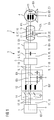
- FIG. 1 are in a schematic representation operationally occurring Erdableitströme IEA or Erdableitteilströme IEA 'and earth faults ES shown on an electric drive system 2, which is operated on an electrical network 1, wherein in case of operation by the ground faults ES dangerous earth fault currents IEF higher frequency in the electric drive system 2 can flow.
- the powered on the electrical network 1 electric drive system 2 has in FIG. 1 an arrangement of electrical components, wherein an electric machine 4, which is a three-phase machine is electrically connected by means of electrical lines 18 to a power converter 3 (in FIG. 1 this electrical line is shown only schematically as suitable for a three-phase system 17).
- the electrical connection of the power converter 3 with the electric machine 4 is designed as a three-phase system 17 and shows one of several circuits 8 of the electric drive system. 2
- the power converter 3 has a rectifier 5 and an inverter 15, wherein the rectifier 5 and the inverter 15 are electrically connected by means of electrical lines 18 to a DC voltage intermediate circuit 6.
- Such converters 3 are also referred to as a frequency converter with DC intermediate circuit 6.
- the electrical connection of the rectifier 5 to the inverter 15 is thus designed as a DC system 16 and shows another of several circuits 8 of the electric drive system. 2
- the electric drive system 2 is starting from the power converter 3 by means of electrical lines 18 to the electrical network 1 electrically connected.
- this electrical connection which is designed as a three-phase system 17, between the electrical network 1 and the power converter 3 of the electric drive system 2, a known from the prior art MFC circuit breaker 14 and a line filter 12 are electrically connected, wherein the line filter 12 is also a part of electric drive system 2 can be.
- conductor-earth capacities 11 are present during operation (shown in FIG. 1 ), which are in electrical connection with the ground or protective conductor potential.
- the conductor earth capacitances 11, for example the electrical lines 18, are co-determined, inter alia, by their insulating jacket 19.
- the electrical network 1 and the mains filter 12 are each connected to the ground or protective conductor potential.
- Operational Erdableitströme IEA high frequency flow now, systemimmanent generated by the power converter 3 of the electric drive system 2, via the conductor ground capacitances 11 to Erd- or protective earth potential, of the operationally generated earth leakage currents IEA high frequency mostly only operational Erdableitteilströme IEA 'high frequency over the ground or protective conductor potential to the electrical network 1 and from there via the residual current circuit breaker 14 back into the electric drive system 2 arrive. Accordingly, a large part of the operationally generated earth leakage current IEA of high frequency is filtered out by means of the network filter 12.
- Known residual current circuit breaker 14 interpret this Erdableitteilstrom IEA 'high frequency usually as a dangerous ground fault current IEF, which by a ground fault ES with predominantly ohmic conductor-ground impedance ZO, for example, on the electrical line 18 between the power converter 3 and the electric machine 4 or in the electrical Machine itself has occurred, in this case, however, has not occurred. As a result of this interpretation, the residual current circuit breaker 14 triggers and disconnects the electric drive system 2 abruptly and undesirably from the electrical network 1.
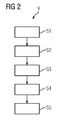
- FIG. 2 shows a structural diagram with essential steps of the inventive method V for detection and shutdown a dangerous earth fault current IEF higher frequency for an operated on an electrical network 1 electric drive system 2 with a power converter 3 and an electric drive machine 4 according to FIG. 1 ,
- a common-mode voltage UCM is generated in the converter 3, which has a specific common-mode voltage component UCMA at a selected low frequency.
- the specific common-mode voltage component UCMA corresponds to an expected voltage value, which is known as a parameter of the method V and / or whose generation can be checked.
- step S2 of the method V flows in the case of a ground fault ES on the electric drive system 2 due to the specific common mode voltage component UCMA by a predominantly ohmic conductor-ground impedance ZO at the selected low frequency, a common mode current component ICMA of a common mode current ICM.
- a summation current IS of the common mode current ICM is detected by means of a current detection 7 in one of a plurality of circuits 8 of the electric drive system 2.
- the total current IS can in each of the exemplary in FIG. 1 shown circuits 8 are detected.
- a fourth method step S4 the common mode current component ICMA of the common mode current ICM at the selected low frequency is determined from the total current IS by means of a current evaluation STW.
- a fifth method step S5 of the method V the electric drive system 2 is separated from the electrical network 1 by means of an electrical switching element 13 when the common mode current component ICMA of the common mode current ICM in the selected low frequency reaches a comparison value VW.
- the method V according to the invention thus ensures that operational earth leakage currents IEA or operational earth leakage partial currents IEA 'of high frequency have no influence on the detection of earth faults ES in the electric drive system 2.
- Dangerous ground fault currents IEF regardless of which frequency, can therefore be reliably detected in the case of ground fault ES and against the background of occurring operational earth leakage currents IEA or Erdableitteilströme IEA high frequency or even prevented before their occurrence, which the reliability and sensitivity of the triggering of the electrical switching element 13 significantly improved.
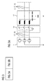
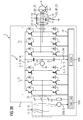
- FIG. 3 shows with the subfigures 3A and 3B a further schematic representation after FIG. 1 with a residual current device 9 according to the invention in the electric drive system 2 for the method V according to the invention FIG. 2 ,
- the arrangement of the electric drive system 2 on the electrical network 1 in FIG. 3 corresponds to the off FIG. 1
- the electric drive system 2 has a current detection 7 for detecting a summation current IS from a common mode current ICM.
- the current detection 7 is arranged by way of example in one of the multiple circuits 8 of the electric drive system 2 in the three-phase system 17 at the grid-side converter input 22 of the power converter 3.
- An arrangement of the current detection 7 to a DC voltage intermediate circuit 6 or to a load-side converter output 23 of the power converter 3 is also possible ,
- a common mode current component ICMA is determined by means of the current evaluation STW at a low frequency and with a comparison value VW compared. If it is determined in the comparison as a result of a ground fault ES that the common mode current component ICMA of the common mode current ICM reaches the comparison value VW at the low frequency, an electrical switching element 13 disconnects the electric drive system 2 from the electrical network 1 and prevents a dangerous ground fault current IEF.
- the common mode current component ICMA flows in the case of the ground fault ES over a predominantly low-impedance conductor-ground impedance ZO, in a power converter 3 of the electric drive system 2 by means of a rectifier 5 and / or an inverter 15, a common mode voltage UCM with a specific common mode voltage component UCMA generated at low frequency.
- the rectifier 5 shown here is designed as a controlled rectifier 21.
- the common-mode voltage UCM in the exemplary embodiment of FIG. 3 ( 3B ) detected by way of example by means of a voltage detection 10 on the DC voltage intermediate circuit 6.
- a voltage detection 10 on the DC voltage intermediate circuit 6 In the case of an arrangement of two DC voltage intermediate capacitances 25 on the DC voltage intermediate circuit 6, it is advantageous to detect the common mode voltage UCM at a midpoint 24 formed between the DC intermediate capacitances 25 with respect to the earth conductor or protective conductor potential.
- the voltage detection 10 can also be arranged on another of the circuits 8 after the DC intermediate circuit 6 of the power converter 3, for example in one of the circuits 8, which is arranged as a three-phase system 17 with the electric machine 4, starting from the load-side converter output 23 of the power converter 3.
- the determined common-mode voltage component UCMA is determined at low frequency and can be compared with the expected voltage value. If the determined common-mode voltage component UCMA does not reach the expected value at the low frequency of the common-mode voltage UCM Voltage value, there is a fault of the residual current device 9.
- appropriate measures can be initiated within the electric drive system 2 or beyond (in FIG. 3 not shown), such as a delivery of an error message to safety or operational control systems of the electric drive system 2 connected to an output of a pulse lock to the power converter 3, a separation of the electric drive system 2 from the electrical network 1 by means of a power switch or inducing a very high impedance Ground fault to trigger a before the electric drive system 2 on the electrical network 2 implemented conventional residual current circuit breaker 14, which then triggers accordingly and the electrical network 1 separates.
- the current evaluation STW and the voltage evaluation SPW are in the embodiment of FIG. 3 ( 3B ) is implemented in a processor unit 20.
- the processor unit is further configured to drive both the controlled rectifier 5, 21 as well as the inverter 15 to respectively generate the determined common mode voltage component UCMA at the low frequency of the common mode voltage UCM.
Landscapes
- Engineering & Computer Science (AREA)
- Power Engineering (AREA)
- Physics & Mathematics (AREA)
- General Physics & Mathematics (AREA)
- Inverter Devices (AREA)
- Emergency Protection Circuit Devices (AREA)
Priority Applications (7)
| Application Number | Priority Date | Filing Date | Title |
|---|---|---|---|
| EP16190797.7A EP3300202A1 (fr) | 2016-09-27 | 2016-09-27 | Procédé destiné à éviter un courant de fuite à la terre dangereux de hautes fréquences pour un système d'entraînement électrique |
| ES17752142T ES2769818T3 (es) | 2016-09-27 | 2017-08-17 | Procedimiento para evitar una corriente de fuga a tierra peligrosa de alta frecuencia, para un sistema de accionamiento eléctrico |
| DK17752142.4T DK3485549T3 (da) | 2016-09-27 | 2017-08-17 | Fremgangsmåde til at undgå en farlig jordfejlstrøm med højere frekvens for et elektrisk drivsystem |
| EP17752142.4A EP3485549B1 (fr) | 2016-09-27 | 2017-08-17 | Procédé destiné à éviter un courant de fuite à la terre dangereux de hautes fréquences pour un système d'entraînement électrique |
| US16/336,748 US10734800B2 (en) | 2016-09-27 | 2017-08-17 | Method for preventing a dangerous, higher-frequency earth fault current for an electrical drive system |
| PCT/EP2017/070816 WO2018059823A1 (fr) | 2016-09-27 | 2017-08-17 | Procédé pour éviter un courant de fuite à la terre dangereux de haute fréquence pour un système d'entraînement électrique |
| CN201780040748.6A CN109417287B (zh) | 2016-09-27 | 2017-08-17 | 用于为电驱动系统避免较高频的危险接地故障电流的方法 |
Applications Claiming Priority (1)
| Application Number | Priority Date | Filing Date | Title |
|---|---|---|---|
| EP16190797.7A EP3300202A1 (fr) | 2016-09-27 | 2016-09-27 | Procédé destiné à éviter un courant de fuite à la terre dangereux de hautes fréquences pour un système d'entraînement électrique |
Publications (1)
| Publication Number | Publication Date |
|---|---|
| EP3300202A1 true EP3300202A1 (fr) | 2018-03-28 |
Family
ID=57153259
Family Applications (2)
| Application Number | Title | Priority Date | Filing Date |
|---|---|---|---|
| EP16190797.7A Withdrawn EP3300202A1 (fr) | 2016-09-27 | 2016-09-27 | Procédé destiné à éviter un courant de fuite à la terre dangereux de hautes fréquences pour un système d'entraînement électrique |
| EP17752142.4A Active EP3485549B1 (fr) | 2016-09-27 | 2017-08-17 | Procédé destiné à éviter un courant de fuite à la terre dangereux de hautes fréquences pour un système d'entraînement électrique |
Family Applications After (1)
| Application Number | Title | Priority Date | Filing Date |
|---|---|---|---|
| EP17752142.4A Active EP3485549B1 (fr) | 2016-09-27 | 2017-08-17 | Procédé destiné à éviter un courant de fuite à la terre dangereux de hautes fréquences pour un système d'entraînement électrique |
Country Status (6)
| Country | Link |
|---|---|
| US (1) | US10734800B2 (fr) |
| EP (2) | EP3300202A1 (fr) |
| CN (1) | CN109417287B (fr) |
| DK (1) | DK3485549T3 (fr) |
| ES (1) | ES2769818T3 (fr) |
| WO (1) | WO2018059823A1 (fr) |
Cited By (2)
| Publication number | Priority date | Publication date | Assignee | Title |
|---|---|---|---|---|
| EP3567689A1 (fr) | 2018-05-09 | 2019-11-13 | Siemens Aktiengesellschaft | Circuit protecteur de courants de fuite à limitation de signal d'entrée |
| US20220014013A1 (en) * | 2020-07-07 | 2022-01-13 | Qingchang ZHONG | Power Electronic Converter with a Ground Fault Detection Unit that Shares a Common Ground with both DC Ports and AC Ports |
Families Citing this family (10)
| Publication number | Priority date | Publication date | Assignee | Title |
|---|---|---|---|---|
| US11204396B2 (en) * | 2018-06-12 | 2021-12-21 | Eaton Intelligent Power Limited | Electrical system |
| DE102018121979A1 (de) | 2018-09-10 | 2020-03-12 | Bender Gmbh & Co. Kg | Verfahren zur Isolationsüberwachung eines Umrichter-gespeisten Stromversorgungssystems |
| EP3629041A1 (fr) * | 2018-09-28 | 2020-04-01 | FRONIUS INTERNATIONAL GmbH | Procédé et dispositif de mise en uvre d'un essai de coupure sur un onduleur |
| EP3672050A1 (fr) * | 2018-12-19 | 2020-06-24 | Siemens Aktiengesellschaft | Procédé de fonctionnement d'un dispositif d'alimentation électrique ainsi que dispositif d'alimentation électrique |
| DE102021204209B4 (de) | 2021-04-28 | 2025-06-05 | Bucher Hydraulics Ag | Frequenzumrichter |
| CN115940671A (zh) * | 2021-10-04 | 2023-04-07 | 丹佛斯电力电子有限公司 | 用于抑制在asd上的供电电压中的偶次谐波的效应的开关控制方法 |
| US12352825B2 (en) * | 2022-06-09 | 2025-07-08 | Hamilton Sundstrand Corporation | Common mode voltage feed fault protection |
| US12519412B2 (en) * | 2022-06-09 | 2026-01-06 | Hamilton Sundstrand Corporation | Common mode current feed fault protection |
| US12510606B2 (en) | 2022-09-23 | 2025-12-30 | Hitachi Energy Ltd | Method for detecting earth faults and frequency converter system with earth fault detection |
| CN118011250A (zh) * | 2024-04-10 | 2024-05-10 | 柔储技术(佛山)有限公司 | 基于pcs自身电压注入的储能系统绝缘阻抗在线监测方法 |
Citations (3)
| Publication number | Priority date | Publication date | Assignee | Title |
|---|---|---|---|---|
| US4896115A (en) * | 1987-06-04 | 1990-01-23 | Merlin Gerin | Electrical network insulation monitoring and measuring device |
| EP1229629A2 (fr) * | 2001-02-02 | 2002-08-07 | Canon Kabushiki Kaisha | Procédé et appareil servant a détecter un courant de défaut de mise à la terre d'un système de génération d'énergie solaire |
| EP2568560A1 (fr) * | 2011-09-07 | 2013-03-13 | Siemens Aktiengesellschaft | Convertisseur de fréquence et procédé de reconnaissance et de blocage d'un courant de fuite dans un convertisseur de fréquence |
Family Cites Families (6)
| Publication number | Priority date | Publication date | Assignee | Title |
|---|---|---|---|---|
| KR100566437B1 (ko) * | 2003-11-11 | 2006-03-31 | 엘에스산전 주식회사 | 위상천이를 이용한 인버터 고장 검출 장치 및 방법 |
| FI119212B (fi) * | 2006-12-14 | 2008-08-29 | Abb Oy | Taajuusmuuttajan maasulkusuojaus |
| FI120565B (fi) * | 2007-12-20 | 2009-11-30 | Abb Oy | Menetelmä ja laitteisto maasulun havaitsemiseen |
| JP5701631B2 (ja) * | 2011-02-03 | 2015-04-15 | 株式会社東芝 | 漏れ電流抑制回路 |
| EP2568557B1 (fr) * | 2011-09-07 | 2014-02-26 | Siemens Aktiengesellschaft | Procédé de fonctionnement d'un disjoncteur à courant de fuite et disjoncteur à courant de fuite pour un convertisseur de courant |
| EP3136526B8 (fr) * | 2015-08-25 | 2022-12-21 | GE Energy Power Conversion Technology Ltd | Procédés de protection de défaut à la terre |
-
2016
- 2016-09-27 EP EP16190797.7A patent/EP3300202A1/fr not_active Withdrawn
-
2017
- 2017-08-17 US US16/336,748 patent/US10734800B2/en active Active
- 2017-08-17 DK DK17752142.4T patent/DK3485549T3/da active
- 2017-08-17 EP EP17752142.4A patent/EP3485549B1/fr active Active
- 2017-08-17 ES ES17752142T patent/ES2769818T3/es active Active
- 2017-08-17 CN CN201780040748.6A patent/CN109417287B/zh active Active
- 2017-08-17 WO PCT/EP2017/070816 patent/WO2018059823A1/fr not_active Ceased
Patent Citations (3)
| Publication number | Priority date | Publication date | Assignee | Title |
|---|---|---|---|---|
| US4896115A (en) * | 1987-06-04 | 1990-01-23 | Merlin Gerin | Electrical network insulation monitoring and measuring device |
| EP1229629A2 (fr) * | 2001-02-02 | 2002-08-07 | Canon Kabushiki Kaisha | Procédé et appareil servant a détecter un courant de défaut de mise à la terre d'un système de génération d'énergie solaire |
| EP2568560A1 (fr) * | 2011-09-07 | 2013-03-13 | Siemens Aktiengesellschaft | Convertisseur de fréquence et procédé de reconnaissance et de blocage d'un courant de fuite dans un convertisseur de fréquence |
Cited By (2)
| Publication number | Priority date | Publication date | Assignee | Title |
|---|---|---|---|---|
| EP3567689A1 (fr) | 2018-05-09 | 2019-11-13 | Siemens Aktiengesellschaft | Circuit protecteur de courants de fuite à limitation de signal d'entrée |
| US20220014013A1 (en) * | 2020-07-07 | 2022-01-13 | Qingchang ZHONG | Power Electronic Converter with a Ground Fault Detection Unit that Shares a Common Ground with both DC Ports and AC Ports |
Also Published As
| Publication number | Publication date |
|---|---|
| US10734800B2 (en) | 2020-08-04 |
| CN109417287A (zh) | 2019-03-01 |
| WO2018059823A1 (fr) | 2018-04-05 |
| CN109417287B (zh) | 2020-04-14 |
| EP3485549A1 (fr) | 2019-05-22 |
| ES2769818T3 (es) | 2020-06-29 |
| EP3485549B1 (fr) | 2019-11-06 |
| US20190363533A1 (en) | 2019-11-28 |
| DK3485549T3 (da) | 2020-02-03 |
Similar Documents
| Publication | Publication Date | Title |
|---|---|---|
| EP3485549B1 (fr) | Procédé destiné à éviter un courant de fuite à la terre dangereux de hautes fréquences pour un système d'entraînement électrique | |
| DE102015207456B3 (de) | Isolationsüberwachungsgerät mit Spannungsüberwachung und zugrunde liegendes Verfahren | |
| DE19930122C1 (de) | Verfahren zur Verhinderung des Draufschaltens auf in Abzweigen bestehende elektrische Kurzschlüsse und zugehörige Anordnung | |
| EP3059828B1 (fr) | Dispositif et procede de detection de courant differentiel | |
| EP3435504B1 (fr) | Procédé, ensembles de circuit électriques et appareils de surveillance de l'isolation pour une surveillance d'isolation résistante au brouillage d'un système d'alimentation électrique pourvu d'un convertisseur | |
| DE112010002226T5 (de) | Verfahren und Vorrichtungen zur Erdschlussüberwachung mittels Multifrequenz-Fehlerstromschutzschalter | |
| EP3351951B1 (fr) | Procédé et dispositif de détection d'une rupture d'une connexion de fils de protection au moyen d'un spectre de courant de fuite | |
| DE10154354A1 (de) | Kurzschlusslichtbogen-Schaltungsunterbrechungs vorrichtung und diese betreffende Verfahren | |
| DE102015208725B3 (de) | Verfahren und Vorrichtung zur Abschaltung eines Isolationsfehler-behafteten Anlagenteils eines ungeerdeten Stromversorgungssystems | |
| DE102007007263A1 (de) | Fehlerstrom-Schutzschalter | |
| DE102015214615A1 (de) | Verfahren und Vorrichtungen zur erweiterten Isolationsfehlersuche mit multifunktionalem Prüfstrom | |
| DE102011001340A1 (de) | Elektrische Vorrichtung für den Kurzschlussschutz einer Drehstromlast in einem Drehstromsystem | |
| EP3931926B1 (fr) | Détection d'une perte à la terre dans un réseau à courant continu | |
| EP0909956B1 (fr) | Procédé et détermination de la résistance d'un réseau de distribution électrique | |
| DE3429067A1 (de) | Schaltung zur kontinuierlichen ueberwachung des erdungswiderstandes elektrischer geraete | |
| EP4099029A1 (fr) | Dispositif de circuit électrique destiné à la surveillance d'isolement conforme aux normes, à arrêt rapide lors de la détection du raccordement à la terre pour un système d'alimentation électrique non mis à la terre | |
| DE102011011984B4 (de) | Fehlerstrom-Schutzeinrichtung mit frequenzabhängiger Schaltung zur Spannungsvervielfachung | |
| DE102011082554B4 (de) | Verfahren zur Bestimmung eines Erdschlussstroms in einem erdschlussbehafteten Drehstromnetz | |
| DE102015200008A1 (de) | Offset Fehlerstrom-Schutzeinrichtung | |
| DE102018204041B4 (de) | Brandschutzschalter, Niederspannungsstromkreis und Verfahren für serielle Fehlerlichtbögen | |
| EP3048685B3 (fr) | Dispositif de protection de courant de fuite et procédé de commutation de contacts de commutation du dispositif de protection de courant de fuite | |
| DE102018204039B4 (de) | Brandschutzschalter, Niederspannungsstromkreis und Verfahren für serielle Fehlerlichtbögen | |
| DE60133059T2 (de) | Drahtbruchdetektion in einem elektrischen Netz | |
| WO2021110844A1 (fr) | Détection d'état de commutation d'élément de commutation électromécanique | |
| EP3221942B1 (fr) | Interrupteur de protection contre les courants de court-circuit |
Legal Events
| Date | Code | Title | Description |
|---|---|---|---|
| PUAI | Public reference made under article 153(3) epc to a published international application that has entered the european phase |
Free format text: ORIGINAL CODE: 0009012 |
|
| AK | Designated contracting states |
Kind code of ref document: A1 Designated state(s): AL AT BE BG CH CY CZ DE DK EE ES FI FR GB GR HR HU IE IS IT LI LT LU LV MC MK MT NL NO PL PT RO RS SE SI SK SM TR |
|
| AX | Request for extension of the european patent |
Extension state: BA ME |
|
| STAA | Information on the status of an ep patent application or granted ep patent |
Free format text: STATUS: THE APPLICATION IS DEEMED TO BE WITHDRAWN |
|
| 18D | Application deemed to be withdrawn |
Effective date: 20180929 |