EP3300209B1 - Energieeffizientes energieerzeugungs- und energieverbrauchssystem und verfahren zum energyeffizienten betrieben dieses systems - Google Patents
Energieeffizientes energieerzeugungs- und energieverbrauchssystem und verfahren zum energyeffizienten betrieben dieses systems Download PDFInfo
- Publication number
- EP3300209B1 EP3300209B1 EP16190644.1A EP16190644A EP3300209B1 EP 3300209 B1 EP3300209 B1 EP 3300209B1 EP 16190644 A EP16190644 A EP 16190644A EP 3300209 B1 EP3300209 B1 EP 3300209B1
- Authority
- EP
- European Patent Office
- Prior art keywords
- control device
- energy
- electronic control
- power
- energy efficient
- Prior art date
- Legal status (The legal status is an assumption and is not a legal conclusion. Google has not performed a legal analysis and makes no representation as to the accuracy of the status listed.)
- Active
Links
Images


Classifications
-
- H—ELECTRICITY
- H05—ELECTRIC TECHNIQUES NOT OTHERWISE PROVIDED FOR
- H05B—ELECTRIC HEATING; ELECTRIC LIGHT SOURCES NOT OTHERWISE PROVIDED FOR; CIRCUIT ARRANGEMENTS FOR ELECTRIC LIGHT SOURCES, IN GENERAL
- H05B1/00—Details of electric heating devices
- H05B1/02—Automatic switching arrangements specially adapted to apparatus ; Control of heating devices
- H05B1/0227—Applications
- H05B1/0252—Domestic applications
- H05B1/0275—Heating of spaces, e.g. rooms, wardrobes
- H05B1/0283—For heating of fluids, e.g. water heaters
-
- F—MECHANICAL ENGINEERING; LIGHTING; HEATING; WEAPONS; BLASTING
- F24—HEATING; RANGES; VENTILATING
- F24D—DOMESTIC- OR SPACE-HEATING SYSTEMS, e.g. CENTRAL HEATING SYSTEMS; DOMESTIC HOT-WATER SUPPLY SYSTEMS; ELEMENTS OR COMPONENTS THEREFOR
- F24D19/00—Details
- F24D19/10—Arrangement or mounting of control or safety devices
- F24D19/1006—Arrangement or mounting of control or safety devices for water heating systems
- F24D19/1051—Arrangement or mounting of control or safety devices for water heating systems for domestic hot water
- F24D19/1057—Arrangement or mounting of control or safety devices for water heating systems for domestic hot water the system uses solar energy
-
- G—PHYSICS
- G05—CONTROLLING; REGULATING
- G05D—SYSTEMS FOR CONTROLLING OR REGULATING NON-ELECTRIC VARIABLES
- G05D23/00—Control of temperature
- G05D23/19—Control of temperature characterised by the use of electric means
- G05D23/1919—Control of temperature characterised by the use of electric means characterised by the type of controller
- G05D23/1924—Control of temperature characterised by the use of electric means characterised by the type of controller using thermal energy, the availability of which is aleatory
-
- H—ELECTRICITY
- H02—GENERATION; CONVERSION OR DISTRIBUTION OF ELECTRIC POWER
- H02J—ELECTRIC POWER NETWORKS; CIRCUIT ARRANGEMENTS OR SYSTEMS FOR SUPPLYING OR DISTRIBUTING ELECTRIC POWER; SYSTEMS FOR STORING ELECTRIC ENERGY
- H02J3/00—Circuit arrangements for AC mains or AC distribution networks
- H02J3/38—Arrangements for feeding a single network from two or more generators or sources in parallel; Arrangements for feeding already energised networks from additional generators or sources in parallel
- H02J3/381—Dispersed generators
-
- H—ELECTRICITY
- H02—GENERATION; CONVERSION OR DISTRIBUTION OF ELECTRIC POWER
- H02J—ELECTRIC POWER NETWORKS; CIRCUIT ARRANGEMENTS OR SYSTEMS FOR SUPPLYING OR DISTRIBUTING ELECTRIC POWER; SYSTEMS FOR STORING ELECTRIC ENERGY
- H02J2101/00—Supply or distribution of decentralised, dispersed or local electric power generation
- H02J2101/20—Dispersed power generation using renewable energy sources
- H02J2101/22—Solar energy
- H02J2101/24—Photovoltaics
-
- Y—GENERAL TAGGING OF NEW TECHNOLOGICAL DEVELOPMENTS; GENERAL TAGGING OF CROSS-SECTIONAL TECHNOLOGIES SPANNING OVER SEVERAL SECTIONS OF THE IPC; TECHNICAL SUBJECTS COVERED BY FORMER USPC CROSS-REFERENCE ART COLLECTIONS [XRACs] AND DIGESTS
- Y02—TECHNOLOGIES OR APPLICATIONS FOR MITIGATION OR ADAPTATION AGAINST CLIMATE CHANGE
- Y02E—REDUCTION OF GREENHOUSE GAS [GHG] EMISSIONS, RELATED TO ENERGY GENERATION, TRANSMISSION OR DISTRIBUTION
- Y02E10/00—Energy generation through renewable energy sources
- Y02E10/50—Photovoltaic [PV] energy
- Y02E10/56—Power conversion systems, e.g. maximum power point trackers
Definitions
- the invention relates to the field of energy generation and consumption systems, more particularly to energy flexible systems of that kind.
- the invention also relates to a method for energy efficient operating of an energy generation and consumption system.
- Today electrical systems are typically constructed as a combination of sub-systems or other arrangements, in order to realize the required global performance. While one might expect to build such combination as a mere concatenation or serial connection of such sub-systems, the nature of part of the used devices, in particular a full electronic realization, in combination with their multi-functional character, especially versus their primary function (like temperature regulation) and other safety functions, brings about technical considerations with respect to the way of connecting, in order to guarantee the by technical standard required performance.
- a typical home photovoltaic (PV) installation usually injects more than 60% of the produced energy in the grid during the day.
- a so-called Generated Power Diverter or GPD helps auto-consuming the surplus power locally generated.
- the GPD system as known from the art however has its limits, particularly regarding compatibility and safety. A solution is needed in order to address these limits.
- a prior art example of photovoltaic DC heater system is described in US2015104160 A1 . It includes a temperature based cut-off control loop to avoid overheating.
- renewable energy like PV
- a kind of storage e.g. use of water heating
- the means for providing electrical power is provided with a plurality of available power lines, and moreover all these available power lines are arranged in the same way. More particularly, it may be that not only the power lines between the means for providing electrical power and first electronic device are according to a specific and similar configuration, also the power lines between first and second electronic control device, and between second electronic control device and the to be electrically powered device for electrical heating respectively are arranged in the same way. Such configuration is for instance referred to as either a 2-phase configuration or either a 3-phase configuration.
- the first electronic control device is only capable of providing on-off control based on a reference temperature
- the second electronic control device is capable of providing variable power control, e.g. variable voltage and/or variable current control. It may be that the first electronic control device is provided with safety protection regulation, such as for instance an overheating protection.
- the system may further be operable solely by use of a (grid) power sensor being part of the power supply control device - and solely used thereby; and a temperature sensor being part of the first electronic control device - and solely used thereby.
- a (grid) power sensor being part of the power supply control device - and solely used thereby
- a temperature sensor being part of the first electronic control device - and solely used thereby.
- power sensor could be a current sensor.
- the invention relates to energy efficient energy generation and consumption systems, comprising an energy supply installation; a power supply control device adapted to determine whether it is efficient to supply the generated energy either to the grid or use otherwise by energy consuming devices, preferably with an energy storage capability; in a further particular combination with an electrical heating arrangement in itself comprising of a to be electrically powered device for electrical heating; a first control device, adapted for determining the achieved temperature (by the to be electrically powered device); a second electronic control device, adapted for determining energy efficient powering conditions, whereby the first electronic control device being fully electronic.
- the energy supply installation is for example a photovoltaic energy supply system, or delivered by another local energy source (for example a micro-cogeneration unit).
- the invention provides a global solution wherein one or more of the following features are used, in particular a particular ordering of the connection, a particular implementation on the power lines, a selected way of power control.
- the invented solution provides a complex energy efficient operating of an energy generation and consumption system while still being based only on two simple decoupled control loops and requiring only a minimal amount of sensors. Allowing the use of a Generated Power Diverter or GPD with variable voltage outputs with an electronic (water boiler) thermostat, the invention provides a new scheme on how to use a GPD that keeps all electronic thermostat functions and safety.
- a GPD system according to the art is depicted in Figure 4 . This typical installation of a GPD shown comprises a current sensor 41, a sensor transmitter 42 and a GPD controller 43.
- the current sensor 41 is based on current clamps, placed around the main feed just after the utility meter 44 to measure the exported or imported current to the grid.
- the sensor transmitter 42 transmits the exported or imported power values to the GPD controller 43. This transmission is for instance performed via a radio link or RF communication 45.
- the GPD controller 43 regulates the energy supplied to the water heater 46 by regulating the voltage at the water heater inlet 47, typically between 80V to 230V.
- the main consumer unit or console 40 which is connected to the PV power switch or PV system isolator 49.
- An immersion double pole isolator 48 connects the GPD controller 43 with the main consumer unit 40 via an immersion circuit.
- a water heater 46 should be equipped with a particular thermal cut off switch.
- the overheating protection provided by the thermal cutoff is directly included in the thermostat, usually with two switches in series.
- the GPD controller 53 is wired in series with the thermostat 54, as shown in Figure 5 . Therefore, the overheating protection in case of a faulty thermostat is always maintained.
- a mechanical thermostat 54 varying the input voltage has no effect on the correct functioning of the thermostat since it relies on thermo-mechanical properties for temperature regulation. Further illustrated in Figure 5 is a heating element 55.
- the electronic thermostat can be split into 3 parts: a thermo-well, a regulation circuit and a power distribution circuit.
- the thermo-well comprises of two circuits: one circuit for the temperature sensors, and a second safety circuit composed of thermal fuse triggering overheating protection defined according to a particular heater product standard.
- the regulation circuit which is an electronic circuit, is meant to regulate the temperature according to the desired set point by controlling output relays (ON/OFF regulation).
- the power distribution circuit that feeds the water elements is composed of relays controlled by the electronic circuit.
- the electronic thermostat is fed at its inlet by a 230V supply, the output of the thermostat is wired directly to the inlet of the heating element, the output is controlled using electrical switches with two positions: closed (the water heater is on heat position) or opened (the feeding circuit is opened and the water heater is not warming up, no current flowing through the resistor).
- the open position can occur in two circumstances: either in normal use when the water boiler has reached its desired temperature and the electronic thermostat ordered to open the feeding circuit; or when the water boiler has reached the overheating limits defined by particular standards.
- the invention provides a solution wherein the GPD controller 63 is wired between the thermostat 62 and the heating element 64 as shown in Figure 6 .
- a control switch 60 and a controlled push button 61 are depicted within its symbol representation - even though in practice both functions are realized by the same set of switches.
- the thermostat is placed before the GPD controller 63 that feeds directly the heating element 64.
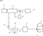
- the thermostat 82 keeps full control of the heating of the resistors of the water boiler 76; the GPD controller 73 only regulates the power that is provided by the thermostat 82 when power is available. In case of any regulation issue and overheating the thermostat 82 will open the feeding relays cutting any power that feeds via the GPD controller 73 the heating elements 77.
- This system works with electronic and mechanical thermostat, and keeps all the current electronic thermostat functionalities.
- the other elements in Figure 7 are like in Figure 4 a current sensor 71, a sensor transmitter 72, the utility meter 74, the main consumer unit or console 70, which is connected to the PV power switch or PV system isolator 79.
- An immersion double pole isolator 78 connects the GPD controller 73 with the main consumer unit 70 via an immersion circuit.
Landscapes
- Engineering & Computer Science (AREA)
- Physics & Mathematics (AREA)
- Chemical & Material Sciences (AREA)
- Power Engineering (AREA)
- Life Sciences & Earth Sciences (AREA)
- Sustainable Development (AREA)
- Sustainable Energy (AREA)
- Thermal Sciences (AREA)
- Combustion & Propulsion (AREA)
- Mechanical Engineering (AREA)
- General Engineering & Computer Science (AREA)
- Automation & Control Theory (AREA)
- General Physics & Mathematics (AREA)
- Supply And Distribution Of Alternating Current (AREA)
Claims (6)
- Energieeffizientes Energieerzeugungs- und -verbrauchssystem (20), umfassend:einer Energieversorgungsanlage (400); einem Energie verbrauchenden Gerät (110) zum elektrischen Heizen, vorzugsweise mit Energiespeicherfähigkeit; wodurch das System ferner eine Regeleinrichtung zur Energieversorgung (420) umfasst, die so angepasst ist, dass sie bestimmen kann, ob es effizient ist, die erzeugte Energie entweder an das Netz (410) oder zur anderweitigen direkten Verwendung durch das Energie verbrauchende Gerät zu liefern; und eine elektrische Heizanordnung (10), umfassend: einer Einrichtung (100) zum Bereitstellen von elektrischer Energie;einem elektrisch zu betreibenden Gerät (110) zum elektrischen Heizen; einer ersten elektronischen Regeleinrichtung (120), die so angepasst ist, um die erreichte Temperatur zu bestimmen, und die in der Lage ist, auf mindestens einen Teil der Einrichtung (100) einzuwirken, um dementsprechend elektrische Energie bereitzustellen; einer zweiten elektronischen Regeleinrichtung (130), die so angepasst ist, dass sie energieeffiziente Energieversorgungsbedingungen bestimmen kann und in der Lage ist, zumindest auf einen Teil der Einrichtung (100) zum Bereitstellen von elektrischer Energie in Übereinstimmung damit einzuwirken;wobei bei dieser elektrische Heizanordnung zumindest Teil (200) der Einrichtung (100) zum Bereitstellen von elektrischer Energie mit der ersten elektronischen Regeleinrichtung (120) verbunden ist, die zumindest eine erste gesteuerte Stromleitung (210) bereitstellt; wobei mindestens eine erste gesteuerte Stromleitung (210) mit der zweiten elektronischen Regeleinrichtung (130) verbunden ist, die mindestens eine zweite gesteuerte Stromleitung (220) bereitstellt; und wobei mindestens eine zweite gesteuerte Stromleitung (220) mit dem Energie verbrauchenden Gerät (110) verbunden ist, wobei die zweite elektronische Regeleinrichtung (130) Teil der Regeleinrichtung zur Energieversorgung (420) ist und die Einrichtung (100) zum Bereitstellen von elektrischer Energie über die Regeleinrichtung zur Energieversorgung (420) mit der Energieversorgungsanlage (400) oder dem Netz (410) verbunden wird.
- System (20) nach Patentanspruch 1, wobei die Einrichtung (100) zum Bereitstellen von elektrischer Energie der Anordnung (10) mehrere verfügbare Stromleitungen hat, wobei diese mehreren verfügbaren Stromleitungen auf die gleiche Weise angeordnet sind.
- System (20) nach Patentanspruch 1 oder 2, wobei die erste elektronische Regeleinrichtung (120) der Anordnung (10) nur in der Lage ist, eine Ein-/AusSteuerung basierend auf einer Referenztemperatur bereitzustellen, und die zweite elektronische Regeleinrichtung (130) in der Lage ist, eine variable Leistungssteuerung bereitzustellen.
- System (20) nach einem der vorhergehenden Patentansprüche, wobei die erste elektronische Regeleinrichtung (120) mit einer Sicherheitsschutzregelung versehen ist.
- System (20) nach einem der vorhergehenden Patentansprüche, das allein durch die Verwendung eines Leistungssensors (500) betrieben werden kann, der Teil der Steuereinrichtung zur Energieversorgung ist; und einen Temperatursensor (510), der Teil der ersten elektronischen Regeleinrichtung (120) ist.
- Verfahren zum energieeffizienten Betreiben eines Energieerzeugungs- und - verbrauchssystems (20) gemäß den Patentansprüchen 1 bis 5, umfassend den folgenden Schritten: Verwendung eines ersten Regelkreises (300) basierend auf der Temperatur durch Verwenden der ersten elektronischen Regeleinrichtung (120), angepasst zum Bestimmen der erreichten Temperatur, und Verwendung eines zweiten Regelkreises (310) basierend auf dem Energiefluss durch Verwendung der zweiten elektronischen Regeleinrichtung (130), angepasst zum Bestimmen energieeffizienter Leistungsbedingungen, wobei der erste und der zweite Regelkreis (300, 310) vollständig entkoppelt sind.
Priority Applications (1)
| Application Number | Priority Date | Filing Date | Title |
|---|---|---|---|
| EP16190644.1A EP3300209B1 (de) | 2016-09-26 | 2016-09-26 | Energieeffizientes energieerzeugungs- und energieverbrauchssystem und verfahren zum energyeffizienten betrieben dieses systems |
Applications Claiming Priority (1)
| Application Number | Priority Date | Filing Date | Title |
|---|---|---|---|
| EP16190644.1A EP3300209B1 (de) | 2016-09-26 | 2016-09-26 | Energieeffizientes energieerzeugungs- und energieverbrauchssystem und verfahren zum energyeffizienten betrieben dieses systems |
Publications (2)
| Publication Number | Publication Date |
|---|---|
| EP3300209A1 EP3300209A1 (de) | 2018-03-28 |
| EP3300209B1 true EP3300209B1 (de) | 2022-04-20 |
Family
ID=57103819
Family Applications (1)
| Application Number | Title | Priority Date | Filing Date |
|---|---|---|---|
| EP16190644.1A Active EP3300209B1 (de) | 2016-09-26 | 2016-09-26 | Energieeffizientes energieerzeugungs- und energieverbrauchssystem und verfahren zum energyeffizienten betrieben dieses systems |
Country Status (1)
| Country | Link |
|---|---|
| EP (1) | EP3300209B1 (de) |
Citations (2)
| Publication number | Priority date | Publication date | Assignee | Title |
|---|---|---|---|---|
| JP2004194485A (ja) * | 2002-12-13 | 2004-07-08 | Hitachi Home & Life Solutions Inc | エネルギーシステム |
| US20150104160A1 (en) * | 2013-10-10 | 2015-04-16 | Barry Lynn Butler | Photovoltaic dc heater systems |
Family Cites Families (3)
| Publication number | Priority date | Publication date | Assignee | Title |
|---|---|---|---|---|
| ITAN20030039A1 (it) * | 2003-08-04 | 2005-02-05 | Merloni Termosanitari Spa | Termoprotettore elettronico per scaldabagni elettrici. |
| US8590802B2 (en) * | 2009-12-17 | 2013-11-26 | Battelle Memorial Institute | Water heater control module |
| GB2514128B (en) * | 2013-05-14 | 2015-04-01 | Exergy Devices Ltd | Energy management method and apparatus |
-
2016
- 2016-09-26 EP EP16190644.1A patent/EP3300209B1/de active Active
Patent Citations (2)
| Publication number | Priority date | Publication date | Assignee | Title |
|---|---|---|---|---|
| JP2004194485A (ja) * | 2002-12-13 | 2004-07-08 | Hitachi Home & Life Solutions Inc | エネルギーシステム |
| US20150104160A1 (en) * | 2013-10-10 | 2015-04-16 | Barry Lynn Butler | Photovoltaic dc heater systems |
Also Published As
| Publication number | Publication date |
|---|---|
| EP3300209A1 (de) | 2018-03-28 |
Similar Documents
| Publication | Publication Date | Title |
|---|---|---|
| US11106228B2 (en) | Thermal energy storage apparatus, controllers and thermal energy storage control methods | |
| CN107005061B (zh) | 电力管理系统 | |
| EP3063476B1 (de) | Vorrichtung zur temperaturkontrolle, verfahren zu deren betrieb und computerprogrammprodukt | |
| US9885498B2 (en) | Electrical water heater with a dual resistive heating element and a control method for energy management | |
| US9927131B2 (en) | Electric water heater systems for power grids with distributed generation | |
| US9784461B2 (en) | Air conditioner heater control based on power supply cord parameters | |
| RS58968B1 (sr) | Podno grejanje | |
| EP3300209A1 (de) | Energieeffizientes energieerzeugungs- und energieverbrauchssystem | |
| CN201034383Y (zh) | 电热水器用高灵敏度超温保护电路 | |
| US20160313012A1 (en) | Electrical heating apparatus, in particular underfloor heating | |
| CA2867607C (en) | Electrical water heater with a dual resistive heating element and a control method for energy management | |
| EP1757868B1 (de) | Elektrischer Kombinationsboiler | |
| FI83926B (fi) | Foerfarande foer reglering av effekten i en elektrisk bastuugn. | |
| CN203350747U (zh) | 集成式八通道热流道温度控制装置 | |
| CN201892882U (zh) | 热处理设备加热的恒温控制系统 | |
| CN102859286A (zh) | 供热装置的控制装置以及用于控制供热设备的系统 | |
| CA2889401A1 (en) | Electrical heating apparatus, in particular underfloor heating | |
| CN208779964U (zh) | 一种合成炉加热器控制系统 | |
| GB2042710A (en) | Control System for a Hot-water Heating Installation and Heating Installation Provided Therewith | |
| CN107529237A (zh) | 一种智能温控电伴热带 | |
| WO2018176087A1 (en) | Safety circuit and control system for direct current powered hot water system | |
| KR101240135B1 (ko) | 온도 조절장치 | |
| CN103180669B (zh) | 用于调节热水温度的混合装置 | |
| GB2326929A (en) | Device for the control of two electric units | |
| CN116499002B (zh) | 热源通电切断方法、装置及具有其的加热装置、烹饪电器 |
Legal Events
| Date | Code | Title | Description |
|---|---|---|---|
| PUAI | Public reference made under article 153(3) epc to a published international application that has entered the european phase |
Free format text: ORIGINAL CODE: 0009012 |
|
| STAA | Information on the status of an ep patent application or granted ep patent |
Free format text: STATUS: THE APPLICATION HAS BEEN PUBLISHED |
|
| AK | Designated contracting states |
Kind code of ref document: A1 Designated state(s): AL AT BE BG CH CY CZ DE DK EE ES FI FR GB GR HR HU IE IS IT LI LT LU LV MC MK MT NL NO PL PT RO RS SE SI SK SM TR |
|
| AX | Request for extension of the european patent |
Extension state: BA ME |
|
| STAA | Information on the status of an ep patent application or granted ep patent |
Free format text: STATUS: REQUEST FOR EXAMINATION WAS MADE |
|
| 17P | Request for examination filed |
Effective date: 20180927 |
|
| RBV | Designated contracting states (corrected) |
Designated state(s): AL AT BE BG CH CY CZ DE DK EE ES FI FR GB GR HR HU IE IS IT LI LT LU LV MC MK MT NL NO PL PT RO RS SE SI SK SM TR |
|
| STAA | Information on the status of an ep patent application or granted ep patent |
Free format text: STATUS: EXAMINATION IS IN PROGRESS |
|
| 17Q | First examination report despatched |
Effective date: 20200616 |
|
| GRAP | Despatch of communication of intention to grant a patent |
Free format text: ORIGINAL CODE: EPIDOSNIGR1 |
|
| STAA | Information on the status of an ep patent application or granted ep patent |
Free format text: STATUS: GRANT OF PATENT IS INTENDED |
|
| INTG | Intention to grant announced |
Effective date: 20211117 |
|
| GRAS | Grant fee paid |
Free format text: ORIGINAL CODE: EPIDOSNIGR3 |
|
| GRAA | (expected) grant |
Free format text: ORIGINAL CODE: 0009210 |
|
| STAA | Information on the status of an ep patent application or granted ep patent |
Free format text: STATUS: THE PATENT HAS BEEN GRANTED |
|
| AK | Designated contracting states |
Kind code of ref document: B1 Designated state(s): AL AT BE BG CH CY CZ DE DK EE ES FI FR GB GR HR HU IE IS IT LI LT LU LV MC MK MT NL NO PL PT RO RS SE SI SK SM TR |
|
| REG | Reference to a national code |
Ref country code: GB Ref legal event code: FG4D |
|
| REG | Reference to a national code |
Ref country code: CH Ref legal event code: EP |
|
| REG | Reference to a national code |
Ref country code: DE Ref legal event code: R096 Ref document number: 602016071229 Country of ref document: DE |
|
| REG | Reference to a national code |
Ref country code: IE Ref legal event code: FG4D |
|
| REG | Reference to a national code |
Ref country code: AT Ref legal event code: REF Ref document number: 1485960 Country of ref document: AT Kind code of ref document: T Effective date: 20220515 |
|
| REG | Reference to a national code |
Ref country code: LT Ref legal event code: MG9D |
|
| REG | Reference to a national code |
Ref country code: NL Ref legal event code: MP Effective date: 20220420 |
|
| REG | Reference to a national code |
Ref country code: AT Ref legal event code: MK05 Ref document number: 1485960 Country of ref document: AT Kind code of ref document: T Effective date: 20220420 |
|
| PG25 | Lapsed in a contracting state [announced via postgrant information from national office to epo] |
Ref country code: NL Free format text: LAPSE BECAUSE OF FAILURE TO SUBMIT A TRANSLATION OF THE DESCRIPTION OR TO PAY THE FEE WITHIN THE PRESCRIBED TIME-LIMIT Effective date: 20220420 |
|
| PG25 | Lapsed in a contracting state [announced via postgrant information from national office to epo] |
Ref country code: SE Free format text: LAPSE BECAUSE OF FAILURE TO SUBMIT A TRANSLATION OF THE DESCRIPTION OR TO PAY THE FEE WITHIN THE PRESCRIBED TIME-LIMIT Effective date: 20220420 Ref country code: PT Free format text: LAPSE BECAUSE OF FAILURE TO SUBMIT A TRANSLATION OF THE DESCRIPTION OR TO PAY THE FEE WITHIN THE PRESCRIBED TIME-LIMIT Effective date: 20220822 Ref country code: NO Free format text: LAPSE BECAUSE OF FAILURE TO SUBMIT A TRANSLATION OF THE DESCRIPTION OR TO PAY THE FEE WITHIN THE PRESCRIBED TIME-LIMIT Effective date: 20220720 Ref country code: LT Free format text: LAPSE BECAUSE OF FAILURE TO SUBMIT A TRANSLATION OF THE DESCRIPTION OR TO PAY THE FEE WITHIN THE PRESCRIBED TIME-LIMIT Effective date: 20220420 Ref country code: HR Free format text: LAPSE BECAUSE OF FAILURE TO SUBMIT A TRANSLATION OF THE DESCRIPTION OR TO PAY THE FEE WITHIN THE PRESCRIBED TIME-LIMIT Effective date: 20220420 Ref country code: GR Free format text: LAPSE BECAUSE OF FAILURE TO SUBMIT A TRANSLATION OF THE DESCRIPTION OR TO PAY THE FEE WITHIN THE PRESCRIBED TIME-LIMIT Effective date: 20220721 Ref country code: FI Free format text: LAPSE BECAUSE OF FAILURE TO SUBMIT A TRANSLATION OF THE DESCRIPTION OR TO PAY THE FEE WITHIN THE PRESCRIBED TIME-LIMIT Effective date: 20220420 Ref country code: ES Free format text: LAPSE BECAUSE OF FAILURE TO SUBMIT A TRANSLATION OF THE DESCRIPTION OR TO PAY THE FEE WITHIN THE PRESCRIBED TIME-LIMIT Effective date: 20220420 Ref country code: BG Free format text: LAPSE BECAUSE OF FAILURE TO SUBMIT A TRANSLATION OF THE DESCRIPTION OR TO PAY THE FEE WITHIN THE PRESCRIBED TIME-LIMIT Effective date: 20220720 Ref country code: AT Free format text: LAPSE BECAUSE OF FAILURE TO SUBMIT A TRANSLATION OF THE DESCRIPTION OR TO PAY THE FEE WITHIN THE PRESCRIBED TIME-LIMIT Effective date: 20220420 |
|
| PG25 | Lapsed in a contracting state [announced via postgrant information from national office to epo] |
Ref country code: RS Free format text: LAPSE BECAUSE OF FAILURE TO SUBMIT A TRANSLATION OF THE DESCRIPTION OR TO PAY THE FEE WITHIN THE PRESCRIBED TIME-LIMIT Effective date: 20220420 Ref country code: PL Free format text: LAPSE BECAUSE OF FAILURE TO SUBMIT A TRANSLATION OF THE DESCRIPTION OR TO PAY THE FEE WITHIN THE PRESCRIBED TIME-LIMIT Effective date: 20220420 Ref country code: LV Free format text: LAPSE BECAUSE OF FAILURE TO SUBMIT A TRANSLATION OF THE DESCRIPTION OR TO PAY THE FEE WITHIN THE PRESCRIBED TIME-LIMIT Effective date: 20220420 Ref country code: IS Free format text: LAPSE BECAUSE OF FAILURE TO SUBMIT A TRANSLATION OF THE DESCRIPTION OR TO PAY THE FEE WITHIN THE PRESCRIBED TIME-LIMIT Effective date: 20220820 |
|
| REG | Reference to a national code |
Ref country code: DE Ref legal event code: R097 Ref document number: 602016071229 Country of ref document: DE |
|
| PG25 | Lapsed in a contracting state [announced via postgrant information from national office to epo] |
Ref country code: SM Free format text: LAPSE BECAUSE OF FAILURE TO SUBMIT A TRANSLATION OF THE DESCRIPTION OR TO PAY THE FEE WITHIN THE PRESCRIBED TIME-LIMIT Effective date: 20220420 Ref country code: SK Free format text: LAPSE BECAUSE OF FAILURE TO SUBMIT A TRANSLATION OF THE DESCRIPTION OR TO PAY THE FEE WITHIN THE PRESCRIBED TIME-LIMIT Effective date: 20220420 Ref country code: RO Free format text: LAPSE BECAUSE OF FAILURE TO SUBMIT A TRANSLATION OF THE DESCRIPTION OR TO PAY THE FEE WITHIN THE PRESCRIBED TIME-LIMIT Effective date: 20220420 Ref country code: EE Free format text: LAPSE BECAUSE OF FAILURE TO SUBMIT A TRANSLATION OF THE DESCRIPTION OR TO PAY THE FEE WITHIN THE PRESCRIBED TIME-LIMIT Effective date: 20220420 Ref country code: DK Free format text: LAPSE BECAUSE OF FAILURE TO SUBMIT A TRANSLATION OF THE DESCRIPTION OR TO PAY THE FEE WITHIN THE PRESCRIBED TIME-LIMIT Effective date: 20220420 Ref country code: CZ Free format text: LAPSE BECAUSE OF FAILURE TO SUBMIT A TRANSLATION OF THE DESCRIPTION OR TO PAY THE FEE WITHIN THE PRESCRIBED TIME-LIMIT Effective date: 20220420 |
|
| PLBE | No opposition filed within time limit |
Free format text: ORIGINAL CODE: 0009261 |
|
| STAA | Information on the status of an ep patent application or granted ep patent |
Free format text: STATUS: NO OPPOSITION FILED WITHIN TIME LIMIT |
|
| 26N | No opposition filed |
Effective date: 20230123 |
|
| PG25 | Lapsed in a contracting state [announced via postgrant information from national office to epo] |
Ref country code: AL Free format text: LAPSE BECAUSE OF FAILURE TO SUBMIT A TRANSLATION OF THE DESCRIPTION OR TO PAY THE FEE WITHIN THE PRESCRIBED TIME-LIMIT Effective date: 20220420 |
|
| REG | Reference to a national code |
Ref country code: DE Ref legal event code: R119 Ref document number: 602016071229 Country of ref document: DE |
|
| PG25 | Lapsed in a contracting state [announced via postgrant information from national office to epo] |
Ref country code: MC Free format text: LAPSE BECAUSE OF FAILURE TO SUBMIT A TRANSLATION OF THE DESCRIPTION OR TO PAY THE FEE WITHIN THE PRESCRIBED TIME-LIMIT Effective date: 20220420 |
|
| REG | Reference to a national code |
Ref country code: CH Ref legal event code: PL |
|
| GBPC | Gb: european patent ceased through non-payment of renewal fee |
Effective date: 20220926 |
|
| PG25 | Lapsed in a contracting state [announced via postgrant information from national office to epo] |
Ref country code: SI Free format text: LAPSE BECAUSE OF FAILURE TO SUBMIT A TRANSLATION OF THE DESCRIPTION OR TO PAY THE FEE WITHIN THE PRESCRIBED TIME-LIMIT Effective date: 20220420 |
|
| PG25 | Lapsed in a contracting state [announced via postgrant information from national office to epo] |
Ref country code: LU Free format text: LAPSE BECAUSE OF NON-PAYMENT OF DUE FEES Effective date: 20220926 |
|
| PG25 | Lapsed in a contracting state [announced via postgrant information from national office to epo] |
Ref country code: LI Free format text: LAPSE BECAUSE OF NON-PAYMENT OF DUE FEES Effective date: 20220930 Ref country code: IE Free format text: LAPSE BECAUSE OF NON-PAYMENT OF DUE FEES Effective date: 20220926 Ref country code: DE Free format text: LAPSE BECAUSE OF NON-PAYMENT OF DUE FEES Effective date: 20230401 Ref country code: CH Free format text: LAPSE BECAUSE OF NON-PAYMENT OF DUE FEES Effective date: 20220930 |
|
| P01 | Opt-out of the competence of the unified patent court (upc) registered |
Effective date: 20230712 |
|
| PG25 | Lapsed in a contracting state [announced via postgrant information from national office to epo] |
Ref country code: GB Free format text: LAPSE BECAUSE OF NON-PAYMENT OF DUE FEES Effective date: 20220926 |
|
| PG25 | Lapsed in a contracting state [announced via postgrant information from national office to epo] |
Ref country code: IT Free format text: LAPSE BECAUSE OF FAILURE TO SUBMIT A TRANSLATION OF THE DESCRIPTION OR TO PAY THE FEE WITHIN THE PRESCRIBED TIME-LIMIT Effective date: 20220420 |
|
| PG25 | Lapsed in a contracting state [announced via postgrant information from national office to epo] |
Ref country code: HU Free format text: LAPSE BECAUSE OF FAILURE TO SUBMIT A TRANSLATION OF THE DESCRIPTION OR TO PAY THE FEE WITHIN THE PRESCRIBED TIME-LIMIT; INVALID AB INITIO Effective date: 20160926 |
|
| PG25 | Lapsed in a contracting state [announced via postgrant information from national office to epo] |
Ref country code: CY Free format text: LAPSE BECAUSE OF FAILURE TO SUBMIT A TRANSLATION OF THE DESCRIPTION OR TO PAY THE FEE WITHIN THE PRESCRIBED TIME-LIMIT Effective date: 20220420 |
|
| PG25 | Lapsed in a contracting state [announced via postgrant information from national office to epo] |
Ref country code: MK Free format text: LAPSE BECAUSE OF FAILURE TO SUBMIT A TRANSLATION OF THE DESCRIPTION OR TO PAY THE FEE WITHIN THE PRESCRIBED TIME-LIMIT Effective date: 20220420 |
|
| PG25 | Lapsed in a contracting state [announced via postgrant information from national office to epo] |
Ref country code: TR Free format text: LAPSE BECAUSE OF FAILURE TO SUBMIT A TRANSLATION OF THE DESCRIPTION OR TO PAY THE FEE WITHIN THE PRESCRIBED TIME-LIMIT Effective date: 20220420 |
|
| PG25 | Lapsed in a contracting state [announced via postgrant information from national office to epo] |
Ref country code: MT Free format text: LAPSE BECAUSE OF FAILURE TO SUBMIT A TRANSLATION OF THE DESCRIPTION OR TO PAY THE FEE WITHIN THE PRESCRIBED TIME-LIMIT Effective date: 20220420 |
|
| PGFP | Annual fee paid to national office [announced via postgrant information from national office to epo] |
Ref country code: FR Payment date: 20240925 Year of fee payment: 9 |
|
| PG25 | Lapsed in a contracting state [announced via postgrant information from national office to epo] |
Ref country code: BG Free format text: LAPSE BECAUSE OF FAILURE TO SUBMIT A TRANSLATION OF THE DESCRIPTION OR TO PAY THE FEE WITHIN THE PRESCRIBED TIME-LIMIT Effective date: 20220420 |
|
| PG25 | Lapsed in a contracting state [announced via postgrant information from national office to epo] |
Ref country code: BG Free format text: LAPSE BECAUSE OF FAILURE TO SUBMIT A TRANSLATION OF THE DESCRIPTION OR TO PAY THE FEE WITHIN THE PRESCRIBED TIME-LIMIT Effective date: 20220420 |
|
| PGFP | Annual fee paid to national office [announced via postgrant information from national office to epo] |
Ref country code: BE Payment date: 20260127 Year of fee payment: 10 |