EP3300317B1 - Procédé, dispositif et système pour réaliser une liaison de service - Google Patents
Procédé, dispositif et système pour réaliser une liaison de service Download PDFInfo
- Publication number
- EP3300317B1 EP3300317B1 EP15894614.5A EP15894614A EP3300317B1 EP 3300317 B1 EP3300317 B1 EP 3300317B1 EP 15894614 A EP15894614 A EP 15894614A EP 3300317 B1 EP3300317 B1 EP 3300317B1
- Authority
- EP
- European Patent Office
- Prior art keywords
- service chain
- tunnel
- chain path
- path
- identifier
- Prior art date
- Legal status (The legal status is an assumption and is not a legal conclusion. Google has not performed a legal analysis and makes no representation as to the accuracy of the status listed.)
- Not-in-force
Links
- 238000000034 method Methods 0.000 title claims description 123
- 238000011144 upstream manufacturing Methods 0.000 claims description 147
- 238000005538 encapsulation Methods 0.000 claims description 39
- 238000012545 processing Methods 0.000 claims description 36
- 230000005641 tunneling Effects 0.000 claims description 22
- 238000004891 communication Methods 0.000 description 28
- 230000008569 process Effects 0.000 description 23
- 230000006870 function Effects 0.000 description 17
- 238000010586 diagram Methods 0.000 description 16
- 238000012423 maintenance Methods 0.000 description 13
- 230000002093 peripheral effect Effects 0.000 description 8
- 230000003993 interaction Effects 0.000 description 7
- 239000000284 extract Substances 0.000 description 6
- 238000012544 monitoring process Methods 0.000 description 5
- 238000012546 transfer Methods 0.000 description 5
- 230000009471 action Effects 0.000 description 4
- 238000000802 evaporation-induced self-assembly Methods 0.000 description 4
- 230000000694 effects Effects 0.000 description 3
- 241000465502 Tobacco latent virus Species 0.000 description 2
- 238000001914 filtration Methods 0.000 description 2
- 238000007689 inspection Methods 0.000 description 2
- 238000013507 mapping Methods 0.000 description 2
- 229940005022 metadate Drugs 0.000 description 2
- JUMYIBMBTDDLNG-UHFFFAOYSA-N methylphenidate hydrochloride Chemical compound [Cl-].C=1C=CC=CC=1C(C(=O)OC)C1CCCC[NH2+]1 JUMYIBMBTDDLNG-UHFFFAOYSA-N 0.000 description 2
- 238000003672 processing method Methods 0.000 description 2
- 230000011664 signaling Effects 0.000 description 2
- 230000001133 acceleration Effects 0.000 description 1
- 230000005540 biological transmission Effects 0.000 description 1
- 230000008859 change Effects 0.000 description 1
- 230000003247 decreasing effect Effects 0.000 description 1
- 238000005516 engineering process Methods 0.000 description 1
- 238000012986 modification Methods 0.000 description 1
- 230000004048 modification Effects 0.000 description 1
- 230000003287 optical effect Effects 0.000 description 1
- 230000004044 response Effects 0.000 description 1
Images


Classifications
-
- H—ELECTRICITY
- H04—ELECTRIC COMMUNICATION TECHNIQUE
- H04L—TRANSMISSION OF DIGITAL INFORMATION, e.g. TELEGRAPHIC COMMUNICATION
- H04L12/00—Data switching networks
- H04L12/28—Data switching networks characterised by path configuration, e.g. LAN [Local Area Networks] or WAN [Wide Area Networks]
- H04L12/46—Interconnection of networks
- H04L12/4633—Interconnection of networks using encapsulation techniques, e.g. tunneling
-
- H—ELECTRICITY
- H04—ELECTRIC COMMUNICATION TECHNIQUE
- H04L—TRANSMISSION OF DIGITAL INFORMATION, e.g. TELEGRAPHIC COMMUNICATION
- H04L45/00—Routing or path finding of packets in data switching networks
- H04L45/302—Route determination based on requested QoS
- H04L45/306—Route determination based on the nature of the carried application
-
- H—ELECTRICITY
- H04—ELECTRIC COMMUNICATION TECHNIQUE
- H04L—TRANSMISSION OF DIGITAL INFORMATION, e.g. TELEGRAPHIC COMMUNICATION
- H04L12/00—Data switching networks
- H04L12/28—Data switching networks characterised by path configuration, e.g. LAN [Local Area Networks] or WAN [Wide Area Networks]
- H04L12/46—Interconnection of networks
- H04L12/4641—Virtual LANs, VLANs, e.g. virtual private networks [VPN]
-
- H—ELECTRICITY
- H04—ELECTRIC COMMUNICATION TECHNIQUE
- H04L—TRANSMISSION OF DIGITAL INFORMATION, e.g. TELEGRAPHIC COMMUNICATION
- H04L41/00—Arrangements for maintenance, administration or management of data switching networks, e.g. of packet switching networks
- H04L41/50—Network service management, e.g. ensuring proper service fulfilment according to agreements
-
- H—ELECTRICITY
- H04—ELECTRIC COMMUNICATION TECHNIQUE
- H04L—TRANSMISSION OF DIGITAL INFORMATION, e.g. TELEGRAPHIC COMMUNICATION
- H04L45/00—Routing or path finding of packets in data switching networks
- H04L45/38—Flow based routing
-
- H—ELECTRICITY
- H04—ELECTRIC COMMUNICATION TECHNIQUE
- H04L—TRANSMISSION OF DIGITAL INFORMATION, e.g. TELEGRAPHIC COMMUNICATION
- H04L45/00—Routing or path finding of packets in data switching networks
- H04L45/64—Routing or path finding of packets in data switching networks using an overlay routing layer
-
- H—ELECTRICITY
- H04—ELECTRIC COMMUNICATION TECHNIQUE
- H04L—TRANSMISSION OF DIGITAL INFORMATION, e.g. TELEGRAPHIC COMMUNICATION
- H04L47/00—Traffic control in data switching networks
- H04L47/10—Flow control; Congestion control
- H04L47/24—Traffic characterised by specific attributes, e.g. priority or QoS
- H04L47/2441—Traffic characterised by specific attributes, e.g. priority or QoS relying on flow classification, e.g. using integrated services [IntServ]
Definitions
- the present invention relates to the field of communications technologies, and specifically, to a method for implementing a service chain, a device, and a system.
- Value-added services are concatenated to form a service chain (service chain), and applied as a whole to traffic of a user that subscribes to the services.
- service chain Properly orchestrating and managing the service chain help an operator quickly deploy and apply a new type of service in a network and quickly provide or change a service template subscribed to by the user.
- a service chain orchestrator generally delivers policy routing information, piece by piece according to a sequence of service nodes (Service Node, SN) that the service needs to pass through, to each service node on the service chain path separately by using a centralized controller or a conventional network management system, and even to a router on an intermediate non-service node, to ensure end-to-end smoothness of a flow to which the service chain is applied.
- Service Node Service Node
- the document US 2014/362857 A1 shows a method and system with a plurality of network nodes each configured to apply one or more service functions to traffic that passes through the respective network nodes.
- a network node receives packets encapsulated in a service header that includes information defining a variable set of context headers stacked into an association of metadata that is relevant to one or more service functions within a service path comprised of one or more network nodes.
- the network node interprets a forwarding state and a next-hop network node for the service path from the service header, and determines a service action or associated metadata from the set of context headers.
- the document US 2015/003455 A1 shows a method of chaining services for a data packet flow and service node.
- a service chaining policy is associated with the data packet flow and a service path identifier is associated with the service chaining policy. If the service chaining policy involves one or more service nodes to be traversed by the data packet flow for obtaining services in a sequential order, a determination is made for obtaining endpoint identifiers and routing locators of the one or more service nodes using the service path identifier of the service chaining policy.
- a data exchange process is performed with the one or more service nodes using encapsulation of data packets based on the endpoint identifiers and routing locators s of the service nodes to sequentially route the data packet flow to each of the service nodes.
- Document US 2013/163594 A1 shows network topology independent service deployment techniques, i.e. overlay-based packet steering techniques.
- a service-directed packet is received at a first network device.
- the service-directed packet comprises a service header and a service overlay tunnel encapsulation, e.g. layer 2 or layer 3, is added to the packet by a second network device enabled as a service classifier.
- the service classifier encapsulates the packet and inserts the packet into a service path to a service virtualization endpoint front ending one or more service nodes.
- Embodiments of the present invention provide a method for implementing a service chain, a device, and a system to resolve a technical problem that load of a centralized control and management device is relatively heavy and that service chain deployment is relatively difficult in an existing service chain implementation.
- a method for implementing a service chain is provided and used in a service chain-enabled domain network, where service nodes SNs and a service chain path from an ingress SN to an egress SN through an intermediate SN are deployed in the service chain-enabled domain network, the SNs include the ingress SN, the intermediate SN, and the egress SN, and the method includes:
- the first service chain path is a path including a service chain path from the ingress SN to the intermediate SN includes: the first service chain path is the service chain path from the ingress SN to the intermediate SN; and correspondingly, that the second service chain path is a path including a service chain path from the ingress SN to the upstream SN includes: the second service chain path is the service chain path from the ingress SN to the upstream SN.
- the first service chain path is a path including a service chain path from the ingress SN to the intermediate SN includes: the first service chain path is the service chain path from the ingress SN to the egress SN; and correspondingly, that the second service chain path is a path including a service chain path from the ingress SN to the upstream SN includes: the second service chain path is the service chain path from the ingress SN to the egress SN.
- the extended first BGP packet further includes a tunnel type, the tunnel type is a label switched path LSP tunnel, and the establishing, by the intermediate SN, a first tunnel from the intermediate SN to the downstream SN with the downstream SN, and linking the first tunnel to a second tunnel to form one tunnel according to the service chain path identifier, where the second tunnel is a tunnel that is from the upstream SN to the intermediate SN and established by the upstream SN with the intermediate SN, includes:
- the extended first BGP packet carries extended network layer reachability information NLRI
- the extended NLRI includes a length field, a label field, and a service chain policy field
- the label field carries the first label
- the service chain policy field includes a service chain path identifier field carrying the service chain path identifier and a service chain path sequence field carrying the first service chain path.
- the service chain policy field further includes a tunnel type field carrying the LSP tunnel type and/or a service chain policy decision point identifier field carrying a service chain policy decision point identifier.
- the extended first BGP packet further includes a tunnel type, the tunnel type is a network virtualization over layer 3 NV03 tunnel, and the establishing, by the intermediate SN, a first tunnel from the intermediate SN to the downstream SN with the downstream SN, and linking the first tunnel to a second tunnel to form one tunnel according to the service chain path identifier, where the second tunnel is a tunnel that is from the upstream SN to the intermediate SN and established by the upstream SN with the intermediate SN, includes:
- the NVO3 tunnel is specifically a virtual extensible local area network VXLAN tunnel or a network virtualization using generic routing encapsulation NVGRE tunnel, and the method further includes:
- the extended first BGP packet carries extended network layer reachability information NLRI
- the extended NLRI includes a length field, a tunnel destination identifier field, and a service chain policy field
- the tunnel destination identifier field includes at least a local service chain identifier field carrying the first local service chain path identifier and a destination IP address field carrying the IP address of the downstream SN
- the service chain policy field includes a service chain path identifier field carrying the service chain path identifier and a service chain path sequence field carrying the first service chain path.
- the service chain policy field further includes a tunnel type field carrying the NVO3 tunnel type and/or a service chain policy decision point identifier field carrying a service chain policy decision point identifier.
- a method for implementing a service chain is provided and used in a service chain-enabled domain network, where service nodes SNs and a service chain path from an ingress SN to an egress SN are deployed in the service chain-enabled domain network, the SNs include the ingress SN and the egress SN, and the method includes:
- the second service chain path is a path including a service chain path from the ingress SN to the upstream SN includes: the second service chain path is the service chain path from the ingress SN to the upstream SN, or the second service chain path is the service chain path from the ingress SN to the egress SN.
- the method further includes:
- the extended BGP packet carries extended network layer reachability information NLRI
- the extended NLRI includes a length field, a label field, and a service chain policy field
- the label field carries the label
- the service chain policy field includes a service chain path identifier field carrying the service chain path identifier and a service chain path sequence field carrying the second service chain path.
- the service chain policy field further includes a tunnel type field carrying the LSP tunnel type and/or a service chain policy decision point identifier field carrying the identifier for identifying a service chain policy decision point.
- the extended BGP packet carries extended network layer reachability information NLRI
- the extended NLRI includes a length field, a tunnel destination identifier field, and a service chain policy field
- the tunnel destination identifier field includes at least a local service chain identifier field carrying the local service chain path identifier and a destination IP address field carrying an IP address of the downstream SN
- the service chain policy field includes a service chain path identifier field carrying the service chain path identifier and a service chain path sequence field carrying the second service chain path.
- the service chain policy field further includes a tunnel type field carrying the NVO3 tunnel type and/or a service chain policy decision point identifier field carrying the identifier for identifying a service chain policy decision point.
- a method for implementing a service chain is provided and used in a service chain-enabled domain network, where service nodes SNs and a service chain path from an ingress SN to an egress SN are deployed in the service chain-enabled domain network, the SNs include the ingress SN and the egress SN, and the method includes:
- the first service chain path is a path including the ingress SN includes: the first service chain path is the ingress SN, or the first service chain path is the service chain path from the ingress SN to the egress SN.
- the service chain-enabled domain network further includes a flow classifier, the flow classifier is an independent device, and the method further includes:
- the service chain-enabled domain network further includes a flow classifier, the flow classifier is integrated with the ingress SN, and the method further includes:
- the extended BGP packet carries extended network layer reachability information NLRI
- the extended NLRI includes a length field, a label field, and a service chain policy field
- the label field carries the label
- the service chain policy field includes a service chain path identifier field carrying the service chain path identifier and a service chain path sequence field carrying the first service chain path.
- the service chain policy field further includes a tunnel type field carrying the LSP tunnel type and/or a service chain policy decision point identifier field carrying the service chain policy decision point identifier.
- the extended BGP packet carries extended network layer reachability information NLRI
- the extended NLRI includes a length field, a tunnel destination identifier field, and a service chain policy field
- the tunnel destination identifier field includes at least a local service chain identifier field carrying the local service chain path identifier and a destination IP address field carrying an IP address of the downstream SN
- the service chain policy field includes a service chain path identifier field carrying the service chain path identifier and a service chain path sequence field carrying the first service chain path.
- the service chain policy field further includes a tunnel type field carrying the NVO3 tunnel type and/or a service chain policy decision point identifier field carrying the service chain policy decision point identifier.
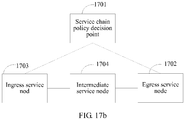
- a method for implementing a service chain is provided and is used in a service chain-enabled domain network, where a service chain policy decision point, service nodes SNs, and a service chain path that is from an ingress SN to an egress SN and orchestrated by the service chain policy decision point are deployed in the service chain-enabled domain network, the SNs include the ingress SN and the egress SN, and the method includes:
- the service chain-enabled domain network further includes a flow classifier, and after the receiving a notification message that is sent by the ingress SN and indicates that the tunnel is established successfully, the method further includes: delivering, by the service chain policy decision point, flow entry information to the ingress SN, where the flow entry information includes information about the flow classifier, and the flow entry information is forwarded by the ingress SN to the flow classifier and used to establish a pull-in tunnel from the flow classifier to the ingress SN.
- the service chain-enabled domain network further includes a flow classifier, the flow classifier is integrated with the ingress SN, and after the receiving a notification message that is sent by the ingress SN and indicates that the tunnel is established successfully, the method further includes: delivering, by the service chain policy decision point, an association message to the ingress SN, where the association message includes an association relationship between the service chain path identifier and a flow steering rule, and the association message is used by the ingress SN to steer a flow of the service chain to the service chain path.
- a service node SN is provided, where the SN is used as an intermediate SN and used in a service chain-enabled domain network, an ingress SN, the intermediate SN, an egress SN, and a service chain path from the ingress SN to the egress SN through the intermediate SN are deployed in the service chain-enabled domain network, and the intermediate SN includes:
- the first service chain path is a path including a service chain path from the ingress SN to the intermediate SN includes: the first service chain path is the service chain path from the ingress SN to the intermediate SN; and correspondingly, that the second service chain path is a path including a service chain path from the ingress SN to the upstream SN includes: the second service chain path is the service chain path from the ingress SN to the upstream SN.
- the first service chain path is a path including a service chain path from the ingress SN to the intermediate SN includes: the first service chain path is the service chain path from the ingress SN to the egress SN; and correspondingly, that the second service chain path is a path including a service chain path from the ingress SN to the upstream SN includes: the second service chain path is the service chain path from the ingress SN to the egress SN.
- the extended first BGP packet further includes a tunnel type, the tunnel type is a label switched path LSP tunnel, and the tunneling module includes:
- the extended first BGP packet carries extended network layer reachability information NLRI
- the extended NLRI includes a length field, a label field, and a service chain policy field
- the label field carries the first label
- the service chain policy field includes a service chain path identifier field carrying the service chain path identifier and a service chain path sequence field carrying the first service chain path.
- the service chain policy field further includes a tunnel type field carrying the LSP tunnel type and/or a service chain policy decision point identifier field carrying a service chain policy decision point identifier.
- the extended first BGP packet further includes a tunnel type
- the tunnel type is a network virtualization over layer 3 NVO3 tunnel
- the tunneling module includes:
- the NVO3 tunnel is specifically a virtual extensible local area network VXLAN tunnel or a network virtualization using generic routing encapsulation NVGRE tunnel, and the intermediate SN further includes:
- the extended first BGP packet carries extended network layer reachability information NLRI
- the extended NLRI includes a length field, a tunnel destination identifier field, and a service chain policy field
- the tunnel destination identifier field includes at least a local service chain identifier field carrying the first local service chain path identifier and a destination IP address field carrying the IP address of the downstream SN
- the service chain policy field includes a service chain path identifier field carrying the service chain path identifier and a service chain path sequence field carrying the first service chain path.
- the service chain policy field further includes a tunnel type field carrying the NVO3 tunnel type and/or a service chain policy decision point identifier field carrying a service chain policy decision point identifier.
- a service node SN is provided, where the SN is used as an egress SN and used in a service chain-enabled domain network, an ingress SN, the egress SN, and a service chain path from the ingress SN to the egress SN are deployed in the service chain-enabled domain network, and the egress SN includes:
- the second service chain path is a path including a service chain path from the ingress SN to the upstream SN includes: the second service chain path is the service chain path from the ingress SN to the upstream SN, or the second service chain path is the service chain path from the ingress SN to the egress SN.
- the obtaining module is further configured to obtain a tunnel type; and the egress SN further includes a tunneling module, where when the tunnel type is a label switched path LSP tunnel, the tunneling module allocates a label to the service chain path, and adds the label to the extended BGP packet; or when the tunnel type is a network virtualization over layer 3 NVO3 tunnel, the tunneling module allocates a local service chain path identifier to the service chain path, generates a tunnel destination identifier according to the local service chain path identifier and an IP address of the egress SN, and adds the tunnel destination identifier to the extended BGP packet.
- the tunnel type is a label switched path LSP tunnel
- the tunneling module allocates a label to the service chain path, and adds the label to the extended BGP packet
- the tunnel type is a network virtualization over layer 3 NVO3 tunnel
- the extended BGP packet carries extended network layer reachability information NLRI
- the extended NLRI includes a length field, a label field, and a service chain policy field
- the label field carries the label
- the service chain policy field includes a service chain path identifier field carrying the service chain path identifier and a service chain path sequence field carrying the second service chain path.
- the service chain policy field further includes a tunnel type field carrying the LSP tunnel type and/or a service chain policy decision point identifier field carrying a service chain policy decision point identifier.
- the extended BGP packet carries extended network layer reachability information NLRI
- the extended NLRI includes a length field, a tunnel destination identifier field, and a service chain policy field
- the tunnel destination identifier field includes at least a local service chain identifier field carrying the local service chain path identifier and a destination IP address field carrying an IP address of the downstream SN
- the service chain policy field includes a service chain path identifier field carrying the service chain path identifier and a service chain path sequence field carrying the second service chain path.
- the service chain policy field further includes a tunnel type field carrying the NVO3 tunnel type and/or a service chain policy decision point identifier field carrying a service chain policy decision point identifier.
- a service node SN is provided, where the SN is used as an ingress SN and used in a service chain-enabled domain network, the ingress SN, an egress SN, and a service chain path from the ingress SN to the egress SN are deployed in the service chain-enabled domain network, and the ingress SN includes:
- the first service chain path is a path including the ingress SN includes: the first service chain path is the ingress SN, or the first service chain path is the service chain path from the ingress SN to the egress SN.
- the service chain-enabled domain network further includes a flow classifier
- the ingress SN further includes:
- the service chain-enabled domain network further includes a flow classifier, the flow classifier is integrated with the ingress SN, and the ingress SN further includes:
- the extended BGP packet carries extended network layer reachability information NLRI
- the extended NLRI includes a length field, a label field, and a service chain policy field
- the label field carries the label
- the service chain policy field includes a service chain path identifier field carrying the service chain path identifier and a service chain path sequence field carrying the first service chain path.
- the service chain policy field further includes a tunnel type field carrying the LSP tunnel type and/or a service chain policy decision point identifier field carrying the service chain policy decision point identifier.
- the extended BGP packet carries extended network layer reachability information NLRI
- the extended NLRI includes a length field, a tunnel destination identifier field, and a service chain policy field
- the tunnel destination identifier field includes at least a local service chain identifier field carrying the local service chain path identifier and a destination IP address field carrying an IP address of the downstream SN
- the service chain policy field includes a service chain path identifier field carrying the service chain path identifier and a service chain path sequence field carrying the first service chain path.
- the service chain policy field further includes a tunnel type field carrying the NVO3 tunnel type and/or a service chain policy decision point identifier field carrying the service chain policy decision point identifier.
- a service chain policy decision point is provided and used in a service chain-enabled domain network, where the service chain policy decision point includes:
- the service chain-enabled domain network further includes a flow classifier; and after the receiving module receives the notification message, the sending module is further configured to send flow entry information to the ingress SN, where the flow entry information includes information about the flow classifier, and the flow entry information is forwarded by the ingress SN to the flow classifier and used to establish a pull-in tunnel from the flow classifier to the ingress SN.
- the service chain-enabled domain network further includes a flow classifier, and the flow classifier is integrated with the ingress SN; and after the receiving module receives the notification message, the sending module is further configured to send an association message to the ingress SN, where the association message includes an association relationship between the service chain path identifier and a flow steering rule, and the association message is used by the ingress SN to steer a flow of the service chain to the service chain path.
- a service chain-enabled domain network system includes a service chain policy decision point, an ingress service node SN, and an egress SN, where the service chain policy decision point is any service chain policy decision point according to the eighth aspect, the ingress SN is any ingress SN according to the seventh aspect, and the egress SN is any egress SN according to the sixth aspect.
- the service chain-enabled domain network system further includes an intermediate SN, where the intermediate SN is any intermediate SN according to the fifth aspect.
- a service node SN determines an upstream SN that is on the first service chain path and immediately adjacent to the SN, and sends an extended BGP packet including the service chain path identifier and a second service chain path to the upstream SN, where the first service chain path is a path including a service chain path from the ingress SN to the intermediate SN, and the second service chain path is a path including a service chain path from the ingress SN to the upstream SN.
- a service chain policy decision point only needs to deliver a service chain policy including the service chain path identifier and a service chain path to an egress SN of a service chain, the service chain policy may be disseminated to the ingress SN of the service chain, and a chain path of the service chain is automatically established. Therefore, automatic service chain deployment is implemented, a service chain deployment operation is simplified, and service chain deployment difficulty is reduced.
- the service chain policy decision point only needs to interact with the egress SN, without delivering the service chain policy to each SN separately, monitoring a route reachability status of each service node, or performing multipoint control and coordination. This reduces objects that interact with the service chain policy decision point, and therefore reduces computation and processing load of the service chain policy decision point. Therefore, operation, administration and maintenance are simple, and extensibility is high.
- Embodiments of the present invention provide a method for implementing a service chain, a device, and a system to provide a service chain solution featuring high extensibility, easy deployment, and simple operation, administration and maintenance.
- the solution can resolve a technical problem that load of a centralized control and management device is relatively heavy and that automatic deployment of a service chain is relatively difficult in a service chain implementation controlled and managed in a centralized manner in the prior art, and can further resolve a technical problem that load of a control and management channel is relatively heavy in the prior art.
- a service chain implementation controlled and managed in a centralized manner is used.
- a centralized control and management device separately delivers policy routing information to each service node on a service chain path to guide each service node on the service chain path in establishing a tunnel from an ingress SN to an egress SN.
- the service chain path includes five SNs denoted by an SN1 to an SN5 respectively, where the SN1 is the ingress SN and the SN5 is the egress SN
- the centralized control and management device needs to separately deliver policy routing information to the five SNs to guide any two immediately adjacent SNs in establishing a tunnel.
- a tunnel is established between the SN1 and the SN2, a tunnel is established between the SN3 and the SN4, a tunnel is established between the SN2 and the SN3, and so on, until the SN1 to the SN5 are all connected by tunnels.
- the SN1 used as the ingress SN establishes a tunnel with the SN2, a flow of the service chain is steered to the established tunnel.
- the embodiments of the present invention provide a method for implementing a service chain, a device, and a system to resolve the technical problems that the load of the centralized control network management device is relatively heavy, and that it is relatively difficult to automatically deploy the service chain, and that the load of the control and management channel is relatively heavy in the existing service chain implementation.
- This embodiment of the present invention provides a method for implementing a service chain.
- the method is used in a service chain-enabled domain network (Service Chain-enabled Domain Network).
- FIG. 1 is a schematic architecture diagram of the service chain-enabled domain network.
- One or more service chain policy decision points and multiple service nodes (SN) configured to provide value-added services are generally deployed in the service chain-enabled domain network.
- a flow classifier may be further deployed in the service chain-enabled domain network.
- An SN is configured to provide one or a group of specific valued-added services, for example, a firewall (FireWall) or deep packet inspection (Deep Packet inspection, DPI), and corresponds to a value-added service module.
- the SN needs to support BGP (Border Gateway Protocol, Border Gateway Protocol) and basic routing, addressing, and forwarding functions, and corresponds to a basic routing module. That is, the SN includes the value-added service module and the basic routing module.
- the two modules may be deployed on one logical/physical network element or different logical/physical network elements (requiring a logical direct connection).
- the basic routing module of the SN can send, according to a service chain path identifier (ID) and/or service flow related metadata (MetaData), a flow to which the service chain is applied, to a value-added service module for processing, and can normally identify, after receiving the flow returned by the value-added service module, a service chain ID corresponding to the flow.
- ID service chain path identifier
- MetalData service flow related metadata
- the service chain policy decision point (or referred to as a service chain controller) is a network device, configured to collect and manage information (for example, types of value-added services, service parameters, and statuses) about the service nodes and network layer reachability information (for example, a route status and a link status) in the service chain-enabled domain network according to a configuration or dynamically by using a protocol, and orchestrate the service nodes according to a requirement of a user to form one or more service chains.
- the requirement of the user may be reflected by a customized service template, a service node status and/or user service flow information (for example, a user identity, and an access location), and the like.
- the service chain may be specifically expressed as a sequence of network layer reachability identifiers (for example, IP addresses and/or VPN (virtual private network, virtual private network) instance identifiers) of the service nodes and/or a sequence of service parameters, and supports dynamic management and search.
- network layer reachability identifiers for example, IP addresses and/or VPN (virtual private network, virtual private network) instance identifiers
- the service chain policy decision point can further perceive a flow identifier of an application-specified service chain and related information (namely, a flow steering rule) of the flow classifier according to a configuration of a service work order or operation and maintenance personnel, and can deliver information such as a service chain policy and a flow steering rule to a corresponding service node and flow classifier in the service chain-enabled domain network by using a southbound interface (such as NetConf/RestConf or RESTful API over HTTP) of the service chain policy decision point.
- a southbound interface such as NetConf/RestConf or RESTful API over HTTP
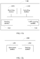
- the basic functional modules of the service chain policy decision point include an orchestrator, a service node information database, and a southbound interface.
- the service node information database is configured to store information of a service node
- the orchestrator is configured to orchestrate a service chain and generate a service chain policy and a flow steering rule
- the southbound interface is a communications interface of the service policy decision point.
- the service chain policy decision point is a logical system, and internal functional modules of the service chain policy decision point may all be deployed on one logical network element, or may be distributed on different network elements. Specific internal interaction manners are not limited in this specification.
- the flow classifier (Flow Classifier, FC) is configured to identify a flow, and forward the flow to an ingress SN of a corresponding service chain according to the flow steering rule.
- the flow classifier may be a device independent of a service node, or may be integrated with a service node.
- this embodiment of the present invention provides a method for implementing a service chain.
- the method is used in a service chain-enabled domain network.
- a service chain policy decision point, service nodes SNs configured to provide value-added services, and a service chain path that is from an ingress SN to an egress SN and orchestrated by the service chain policy decision point are deployed in the service chain-enabled domain network.
- the SNs include the ingress SN and the egress SN.
- the method may include the following steps.
- the egress SN obtains a service chain path identifier and a first service chain path, where the service chain path identifier is used to identify the service chain path, and the first service chain path is the service chain path from the ingress SN to the egress SN.
- the service chain policy decision point deploys or delivers a service chain policy (the service chain policy includes at least the service chain path identifier and the service chain path) to the egress SN of the service chain, and specifically may deliver the service chain policy to the egress SN by using a southbound interface of the service chain policy decision point.
- the egress SN of the service chain may be any SN in the service chain-enabled domain network.
- the service chain policy decision point may directly send the service chain policy to the egress SN, or may send the service chain policy to the egress SN by using another device.
- the service chain policy sent to the egress SN may be in various protocol formats, for example, may be in a network layer reachability information (NLRI) format. If the egress SN receives a service chain policy in a non-NLRI format, the egress SN may convert the service chain policy into the NLRI format.
- NLRI network layer reachability information
- the egress SN determines an upstream SN that is on the first service chain path and immediately adjacent to the egress SN.
- the egress SN sends an extended Border Gateway Protocol BGP packet to the upstream SN, where the extended BGP packet includes the service chain path identifier and a second service chain path, and the second service chain path is a path including a service chain path from the ingress SN to the upstream SN.
- the second service chain path may be the service chain path from the ingress SN to the upstream SN, and in this case, it means that the egress SN generates the second service chain path after removing the egress SN from the first service chain path; or the second service chain path may be the service chain path from the ingress SN to the egress SN, and in this case, it means that the second service chain path and the first service chain path are the same.
- upstream and downstream are based on a service data transmission direction, that is, upstream and downstream in a direction from the ingress SN to the egress SN.
- the "immediately adjacent” means being immediately adjacent on the service chain path, but does not mean that the egress SN is directly connected to the upstream SN of the egress SN.
- an intermediate SN may be included or not included between the ingress SN and the egress SN, and the upstream SN may be the ingress SN, or may be the intermediate SN.
- an intermediate forwarding device (that is, a BGP peer node used for forwarding between two SN nodes) may be included or not included between two adjacent SN nodes, namely, between the egress SN and the upstream SN.
- that the egress SN sends an extended BGP packet to the upstream SN includes: first, the extended BGP packet is sent to the intermediate forwarding device, and then the intermediate forwarding device sends the extended BGP packet to the upstream SN.
- Embodiment 4 and Embodiment 5 Details are not further described herein.
- the egress SN obtains a tunnel type, and establishes a tunnel between the upstream SN and the egress SN.
- the tunnel type is used to guide the service node in establishing a forwarding tunnel according to the service chain policy.
- an NVO3 (Network virtualization over Layer 3, network virtualization over layer 3) tunnel may be specified by default, for example, VXLAN (Virtual eXtensible Local Area Network, virtual extensible local area network) or NVGRE (Network Virtualization using Generic Routing Encapsulation, network virtualization using generic routing encapsulation).
- an LSP Label Switch Path, label switched path
- the tunnel type is optional.
- the egress SN allocates a label to the service chain path, and adds the label to the extended BGP packet; or when the tunnel type is a network virtualization over layer 3 NVO3 tunnel, the egress SN allocates a local service chain path identifier to the service chain path, generates a tunnel destination identifier according to the local service chain path identifier and an IP address of the egress SN, and adds the tunnel destination identifier to the extended BGP packet.
- the extended BGP packet may specifically carry extended network layer reachability information NLRI
- the extended NLRI includes a length field, a label field, and a service chain policy field
- the label field carries the label
- the service chain policy field includes a service chain path identifier field carrying the service chain path identifier and a service chain path sequence field carrying the second service chain path.
- the service chain path identifier is used to indicate the service chain path.
- the service chain policy decision point allocates or uses a UUID (Universally Unique Identifier, universally unique identifier).
- UUID Universally Unique Identifier
- the service chain path sequence field indicates a sequence of multiple SNs included on the service chain path, and is used to indicate the service chain path, and may be specifically expressed as a sequence of network layer reachability identifiers (for example, IP addresses and/or VPN instance identifiers) of the service nodes and/or a sequence of service parameters.
- the service chain policy field further includes a tunnel type field carrying the LSP tunnel type and/or a service chain policy decision point identifier field carrying the service chain policy decision point identifier.
- the service chain policy decision point ID is used to indicate a service chain policy decision point, and is optional. When there is only one service chain policy decision point in the service chain-enabled domain network, the service chain policy may not include the service chain policy decision point ID.
- the extended BGP packet may specifically carry extended network layer reachability information NLRI
- the extended NLRI includes a length field, a tunnel destination identifier field, and a service chain policy field
- the tunnel destination identifier field includes at least a local service chain identifier field carrying the local service chain path identifier and a destination IP address field carrying an IP address of the downstream SN
- the service chain policy field includes a service chain path identifier field carrying the service chain path identifier and a service chain path sequence field carrying the second service chain path.
- the service chain policy field further includes a tunnel type field carrying the NVO3 tunnel type and/or a service chain policy decision point identifier field carrying the service chain policy decision point identifier.
- this embodiment of the present invention discloses a method for implementing a service chain.
- an egress SN obtains a service chain path identifier and a first service chain path, where the service chain path identifier is used to identify the service chain path, and the first service chain path is a service chain path from the ingress SN to the egress SN; the egress SN determines an upstream SN that is on the first service chain path and immediately adjacent to the egress SN; and the egress SN sends an extended Border Gateway Protocol BGP packet to the upstream SN, where the extended BGP packet includes the service chain path identifier and a second service chain path, and the second service chain path is a path including a service chain path from the ingress SN to the upstream SN.
- this embodiment of the present invention provides another method for implementing a service chain.
- the method is used in a service chain-enabled domain network.
- a service chain policy decision point, service nodes SNs configured to provide value-added services, and a service chain path that is from an ingress SN to an egress SN through an intermediate SN and orchestrated by the service chain policy decision point are deployed in the service chain-enabled domain network.
- the SNs include the ingress SN, the intermediate SN, and the egress SN.
- the method includes the following steps.
- the intermediate SN receives an extended first Border Gateway Protocol BGP packet sent by a downstream SN that is on the service chain path and immediately adjacent to the intermediate SN, where the extended first BGP packet includes the service chain path identifier and the first service chain path, the service chain path identifier is used to identify the service chain path, and the first service chain path is a path including a service chain path from the ingress SN to the intermediate SN.
- the intermediate SN determines an upstream SN that is on the first service chain path and immediately adjacent to the intermediate SN.
- the intermediate SN sends an extended second BGP packet to the upstream SN, where the extended second BGP packet includes the service chain path identifier and a second service chain path, and the second service chain path is a path including a service chain path from the ingress SN to the upstream SN.
- the first service chain path may be the service chain path from the ingress SN to the intermediate SN; correspondingly, the second service chain path may be the service chain path from the ingress SN to the upstream SN.
- the first service chain path may be the service chain path from the ingress SN to the egress SN; correspondingly, the second service chain path may be the service chain path from the ingress SN to the egress SN.
- the service chain path is not shortened. The complete service chain path is always transferred.
- an intermediate forwarding device that is, another BGP peer node used for forwarding between two SN nodes
- an intermediate forwarding device may be included or not included between two adjacent SN nodes, namely, between the intermediate SN and the upstream SN.
- that the intermediate SN sends an extended second BGP packet to the upstream SN includes: first, the extended second BGP packet is sent to the intermediate forwarding device, and then the intermediate forwarding device sends the extended second BGP packet to the upstream SN.
- any intermediate SN before the egress SN may receive an extended BGP packet sent by a downstream SN of the intermediate SN.
- the intermediate SN may continue to send the extended BGP packet to an upstream SN of the intermediate SN.
- the downstream SN is a next SN immediately adjacent to the intermediate SN on the service chain path
- the upstream SN is a previous SN immediately adjacent to the intermediate SN on the service chain path.
- the method further includes: the intermediate SN establishes a first tunnel from the intermediate SN to the downstream SN with the downstream SN, and links the first tunnel to a second tunnel to form one tunnel according to the service chain path identifier, where the second tunnel is a tunnel that is from the upstream SN to the intermediate SN and established by the upstream SN with the intermediate SN.
- the extended first BGP packet further includes a tunnel type, the tunnel type may include at least a label switched path LSP tunnel and a network virtualization over layer 3 NVO3 tunnel.
- Specific processing manners are as follows:
- the NVO3 tunnel is specifically a virtual extensible local area network VXLAN tunnel or a network virtualization using generic routing encapsulation NVGRE tunnel, and the method further includes:
- the tunnel type is an LSP tunnel
- specific formats of the extended first BGP packet and the extended second BGP packet are consistent with the format of the extended BGP packet described in Embodiment 1. Details are not further described herein again. A difference from Embodiment 1 lies in that a value carried by each field is different.
- the extended BGP packet may be specifically: a local service chain identifier field carries the first local service chain path identifier, a destination IP address field carries the IP address of the downstream SN, and a service chain path sequence field carries the first service chain path.
- This embodiment of the present invention discloses a method for implementing a service chain above. Terms, definitions, and descriptions used in this method keep consistent with those in Embodiment 1. Details are not further described herein again.
- an intermediate SN of a service chain receives an extended first BGP packet sent by a downstream SN that is on the service chain path and immediately adjacent to the intermediate SN
- the intermediate SN establishes a tunnel with the downstream SN and an upstream SN respectively, and links the two tunnels without obtaining an instruction that is used for establishing a tunnel and delivered by a service chain policy decision point. Therefore, this reduces interactions between the service chain policy decision point and the intermediate SN, and reduces computation and processing load of the service chain policy decision point. Therefore, operation, administration and maintenance are simpler, and extensibility is higher. In addition, this helps implement automatic service chain deployment, and helps reduce service chain deployment difficulty.
- this embodiment further provides a method for implementing a service chain.
- the method of this embodiment is performed by an ingress SN of a service chain.
- the method of this embodiment is used in a service chain-enabled domain network.
- a service chain policy decision point, service nodes SNs configured to provide value-added services, and a service chain path that is from an ingress SN to an egress SN and orchestrated by the service chain policy decision point are deployed in the service chain-enabled domain network.
- the SNs include the ingress SN and the egress SN.
- the method of this embodiment may include the following steps.
- the ingress SN receives an extended BGP packet sent by a downstream SN that is on the service chain path and immediately adjacent to the ingress SN, where the extended BGP packet includes a service chain path identifier and a first service chain path, the service chain path identifier is used to identify the service chain path, and the first service chain path is a path including the ingress SN.
- the first service chain path may be the ingress SN; this means that in a process of transferring the service chain path from the egress SN to the ingress SN, an SN is removed from the service chain path every time an SN is passed through, and when the service chain path arrives at the ingress SN, only the ingress SN remains on the service chain path.
- the first service chain path may be the service chain path from the ingress SN to the egress SN; this means that in a process of transferring the service chain path from the egress SN to the ingress SN, the service chain path is not shortened, and the complete service chain path is always transferred.
- the ingress SN establishes a tunnel from the ingress SN to the downstream SN with the downstream SN.
- the ingress SN sends a notification message to a service chain policy decision point after the tunnel is established successfully, where the notification message carries the service chain path identifier.
- the ingress SN may send, to the corresponding service chain policy decision point, a notification message indicating that a forwarding path of the service chain (namely, a service chain path) is established successfully, where the notification message may carry a service chain ID, and may further carry a service chain forwarding path status (for example, established successfully).
- a specific bearing message may be a notify message of NetConf/RestConf or a query response message of a web APP.
- the service chain policy decision point learns, by receiving the notification message sent by the ingress SN, that the service chain forwarding path is established successfully.
- the service chain-enabled domain network further includes a flow classifier (for example, the flow classifier in FIG. 1 ).
- the flow classifier may be deployed in two manners. It may be an independent device, or may be a same device as the ingress SN (that is, the flow classifier is integrated with the ingress device). The following separately describes processing methods in the two deployment manners.
- Manner 1 When the flow classifier is an independent device, the method may further include:
- the flow classifier after receiving the disseminated service chain policy, the flow classifier initiates a tunnel establishment procedure, and establishes a pull-in tunnel of a specified tunnel type with the corresponding ingress SN.
- the ingress SN may establish a mapping relationship between the pull-in tunnel and the service chain path identifier to establish a forwarding path from the flow classifier to the service chain.
- a one-to-one mapping relationship may be established between an identifier of the pull-in tunnel and ⁇ service chain policy decision point identifier, service chain path identifier>.
- the service chain policy decision point may establish an association relationship between a flow steering rule of the applied service chain and the service chain ID, and then may deliver an association message to the flow classifier by using a southbound interface of the service chain policy decision point, so that the flow classifier steers a flow of the service chain to the forwarding path of the service chain.
- the association message may carry information such as a flow identifier, the service chain path identifier, an identifier of the ingress SN of the service chain path, the tunnel type, and a bound interface list on which a flow rule application of the flow classifier is effective.
- the flow identifier may include a group of packet field filter rules, and a specific form may be an ACL (Access Control List, access control list).
- the information about the bound interface list on which the flow rule application is effective may include an interface identifier and a direction in which an interface flow application is effective (for example, an incoming direction, an outgoing direction, or both directions).
- the flow classifier may steer the flow of the service chain to the forwarding path of the service chain according to the flow steering rule by using the pull-in tunnel. As the flow classifier steers the flow matched and hit by the flow identifier from the established pull-in tunnel to the tunnel corresponding to the corresponding service chain forwarding path, SNs on the whole tunnel forwarding path can forward a service flow packet according to tunnel information.
- the egress SN may forward the service flow packet in a conventional L2/L3 (layer 2/layer 3) routing manner again.
- Manner 2 When the flow classifier is integrated with the ingress SN, the method may further include:
- the method further includes: the ingress SN receives a service data packet of the service chain, and performs tunnel encapsulation on the service data packet before sending the service data packet to the downstream SN.
- a specific format of the extended BGP packet is consistent with the format of the extended BGP packet described in Embodiment 1. Details are not further described herein again.
- a difference from Embodiment 1 lies in that a value carried by each field is different.
- the tunnel type is an LSP tunnel
- a label field carries the label
- a service chain path sequence field carries the first service chain path
- the tunnel type is an NVO3 tunnel
- the extended BGP packet may be specifically: a local service chain identifier field carries the local service chain path identifier, a destination IP address field carries an IP address of the downstream SN, and a service chain path sequence field carries the first service chain path.
- This embodiment of the present invention discloses a method for implementing a service chain above. Terms, definitions, and descriptions used in this method keep consistent with those in Embodiments 1 and 2. Details are not further described herein again.
- this embodiment of the present invention discloses a method for implementing a service chain. After an ingress SN of a service chain path obtains an extended BGP packet sent by a downstream SN, the ingress SN establishes a tunnel with the downstream SN without obtaining an instruction that is used for establishing a tunnel and delivered by a service chain policy decision point. Therefore, this reduces interactions between the service chain policy decision point and the ingress SN, and reduces computation and processing load of the service chain policy decision point. Therefore, operation, administration and maintenance are simpler, and extensibility is higher. In addition, this helps implement automatic service chain deployment, and helps reduce service chain deployment difficulty.
- a tunnel type of a service chain is an LSP (label switched path).
- LSP label switched path
- the extended NLRI is newly defined NLRI, and is used to indicate a service chain policy.
- a basic format of the extended NLRI may be ⁇ length (length), Label(s) (label), Service Chain Policy (service chain policy)>.
- a basic format of Service Chain Policy may be ⁇ Controller ID, Service Chain ID, Tunnel Type, SN Number, SN Sequence>, where Controller ID is a service chain policy decision point identifier (optional), Service Chain ID is a service chain path identifier (mandatory), Tunnel Type is a tunnel type (optional), SN Number is a quantity of SNs (optional), and SN Sequence is the service chain path sequence (mandatory).
- a basic format of SN node information in SN Sequence is ⁇ RD (optional, optional), IP Address, Metadata length (optional), Metadata value (optional)>.
- RD is an acronym of route distinguisher, and is a flag indicating to which VPN a route belongs;
- IP Address is an IP address of an SN;
- Metadata length is a metadata length (optional);
- Metadata value is a metadata value (optional).
- SN Number and SN Sequence may be separately defined as new extended path attributes.
- the extended NLRI may be used in MP_REACH_NLRI/MP_UNREACH_NLRI (two path attributes defined in RFC 2858).
- Metadata indicates metadata that the current SN needs to transfer to a next SN in the service chain path sequence.
- Metadata value defines a group of metadata definition and value setting rules, and is used to guide a forwarding plane of the current SN in filling metadata and adding the metadata to a packet, and guide the next SN in obtaining and parsing the metadate from the packet.
- the metadate may be carried optionally. Directly filling with a specific numeric value is only a special case. Specific use is not limited in this specification.
- Tunnel Information is a compact TLV format as follows:
- Type 1 indicates an LSP tunnel.
- Type 2 indicates a VXLAN tunnel.
- a reference code format of SFC Policy is as follows:
- a reference code format of SN Information is as follows:
- Metadata may include a group of defined TLVs that are more refined. A specific format is not limited in the present invention. If Metadata length is 0, it means that the SN Information does not carry metadata.
- service chain is an abbreviation of service function chain
- SFC is an acronym of service function chain (service chain)
- SFC may also be understood as an acronym of service chain.
- the service chain, service function chain, and SFC in this specification have the same meaning, and are all used to represent a service chain.
- BGP supports the extended NLRI and becomes extended BGP.
- a new SAFI Subsequent Address Family Identifier, subsequent address family identifier
- SAFI Subsequent Address Family Identifier, subsequent address family identifier
- an AFI Address Family Identifier, subsequent address family identifier
- an existing standard for example, an AFI of an IPv4 network is 1, an AFI of an IPv6 network is 2, and an AFI of an L2VPN is 25).
- Tunnel establishment is a procedure on a signaling plane.
- the extended NLRI is advertised forward based on BGP in a reverse service chain path sequence.
- Metadata transferred on the signaling plane guides the current SN in filling an original packet with inserted metadata when the current SN processes a service data packet in the service chain, so that the next SN performs corresponding processing according to the metadata that is inserted in the packet by the current SN, for example, a basic forwarding module of the SN selects a specific value-added service module or a value-added service module of the SN extracts a service parameter.
- Each of intermediate SNs receives extended NLRI advertised by a next SN in the service chain path sequence, continues to advertise the extended NLRI to a previous SN, establishes an LSP tunnel with the next SN, and links two LSP tunnels before and after the SN.
- the SN After the SN receives a service chain advertisement (namely, the extended NLRI advertised by the next SN), first, the SN saves service chain policy information indicated by the extended NLRI.
- a service chain advertisement namely, the extended NLRI advertised by the next SN
- an SN extracts an identifier of the SN from an end of the service chain path sequence, obtains an identifier of a previous SN in the service chain path sequence, and removes the identifier of the SN from the service chain path.
- 1 is subtracted from a value of SN Number correspondingly.
- an SN needs to determine a position of the SN on the service chain path according to an identifier of the SN, and obtain an identifier of a previous SN in the service chain path sequence.
- the SN searches for a route according to the identifier of the previous SN in the service chain path sequence, and advertises modified extended NLRI to only a source BGP peer (peer) of the route, where the extended NLRI carries a label allocated by the SN to the service chain.
- the label (Label ID) is a label allocated by the SN locally, and is mapped to ⁇ Controller ID, Service Chain ID> on a one-to-one basis, or is mapped to ⁇ Service Chain ID> on a one-to-one basis.
- the intermediate forwarding device determines, by using the following method, that the intermediate forwarding device is not a destination SN:
- the intermediate forwarding device extracts an identifier of the destination SN from the end of the service chain path sequence, compares an identifier of the intermediate forwarding device with the identifier of the destination SN, and determines that the intermediate forwarding device is not the destination SN.
- the intermediate forwarding device first needs to obtain the destination SN.
- the current destination SN in the service chain path sequence needs to be obtained according to SN Number. For example, if five SN nodes, namely, an SN1, an SN2, an SN3, an SN4, and an SN5, sequentially exist in the service chain path sequence, but SN Number is equal to 3, the SN3 is the current destination SN.
- a field of the destination SN is added to the NLRI to identify the current destination SN. Then the intermediate forwarding device compares the identifier of the intermediate forwarding device with the identifier of the destination SN, and determines that the intermediate forwarding device is not the destination SN.
- the intermediate forwarding device determines that the intermediate forwarding device is not the destination SN, the intermediate forwarding device does not modify ⁇ SN Number, SN Sequence>, but only reallocates a label, searches for a BGP route according to the identifier of the destination SN, continues to advertise the extended NLRI to an upstream BGP peer (PEER) identified by a next hop of the found BGP route on the service chain, and generates a label forwarding table locally.
- PEER upstream BGP peer
- a forwarding path of an underlying (underlay) network may be established depending on a conventional routing and tunneling manner such as conventional IGP (Interior Gateway Protocol, Interior Gateway Protocol)/LDP (Label Distribution Protocol, Label Distribution Protocol).
- the forwarding path is transparent to a service chain forwarding path.
- an LSP crossing non-SNs may be formed between SNs, and multiple such LSPs are seamlessly linked to form an LSP of a whole service chain.
- different service chains may exclusively use an LSP.
- "SN1 to SN2" are orchestrated into two service chains, and two LSPs are actually respectively established between the SN1 and the SN2 for the two service chains.
- the SN may associate two adjacent LSPs by using ⁇ Controller ID, Service Chain ID>, to implement seamless interconnection.
- i is an integer that is greater than 1 but less than M
- M is a quantity of SNs included in the service chain path sequence:
- the intermediate forwarding device is a non-SN BGP peer node that is used for forwarding a service chain data packet only, and may be a router supporting extended BGP. After the router receives the extended NLRI, the router finds that the router is not the last SN in the service chain path sequence (that is, the router is an intermediate forwarding device to arrive at the SN), continues to search for a route according to identifier information of the SN, advertises the extended NLRI to a next-hop router, and assists in establishing a tunnel. In addition to normally advertising a route, the intermediate device between two SNs needs to allocate a label to the service chain, and extended NLRI advertised to an upstream SN should carry the allocated label.
- An ingress SN receives extended NLRI advertised by a downstream SN that is in the service chain path sequence and adjacent to the ingress SN, establishes an LSP tunnel with the downstream SN, and therefore completes establishment of an LSP tunnel from the ingress SN to the egress SN.
- the method further includes: establishing a pull-in tunnel between the flow classifier and the ingress SN of the service chain path.
- the flow classifier may be a provider network edge PE (Provider Edge, provider edge) device.
- a service chain policy decision point may synchronously deliver a piece of flow entry information to the ingress SN of the service chain, to guide the ingress SN in disseminating service chain information carried in the extended NLRI to the flow classifier (in this case, SN Number in the extended NLRI is 0, and no SN Sequence information exists), so as to trigger the flow classifier to establish an LSP with the ingress SN (namely, the pull-in tunnel described above).
- the flow entry information should include a network layer reachability identifier of the flow classifier and the service chain ID.
- a specific message bearing manner may be NetConf/RestConf or RESTful API over HTTP.
- the flow classifier steers a corresponding flow to the ingress SN of the corresponding service chain path. Therefore, a whole path, from the flow classifier to the ingress SN of the service chain to the egress SN of the service chain, is formed by multiple seamlessly linked LSPs, and the packet is forwarded with labels in the whole process.
- establishment of a service chain tunnel is described in detail above by using an example in which the tunnel type of the service chain is an LSP.
- a tunnel type of a service chain is an NVO3 tunnel.
- the NVO3 tunnel is a tunnel based on IP (Internet Protocol, Internet Protocol) or UDP (User Datagram Protocol, User Datagram Protocol), and may be specifically a VXLAN (virtual extensible local area network) or NVGRE (network virtualization using generic routing encapsulation) tunnel.
- VXLAN virtual extensible local area network
- NVGRE network virtualization using generic routing encapsulation
- the extended NLRI is newly defined NLRI, and is used to indicate a service chain policy.
- a basic format of the extended NLRI may be ⁇ length, Tunnel Destination (tunnel description), Service Chain Policy>.
- a basic format of Tunnel Destination may be ⁇ RD (optional), IP Address, Local Service Chain ID>.
- RD is an acronym of route distinguisher, and is a flag indicating to which VPN a route belongs;
- IP Address is an IP address of a previous-hop SN of a current SN;
- Local Service Chain ID local service chain path identifier
- Controller ID is a service chain policy decision point identifier (optional)
- Service Chain ID is a service chain path identifier (mandatory).
- Other definitions and descriptions are the same as those in Embodiment 4. Details are not further described herein again.
- Each of intermediate SNs receives extended NLRI advertised by a next SN in the service chain path sequence, continues to advertise the extended NLRI to a previous SN, establishes an NVO3 tunnel with the next SN, and links two NVO3 tunnels before and after the SN.
- the SN After the SN receives a service chain advertisement (namely, the extended NLRI advertised by the next SN), first, the SN saves the extended NLRI.
- a service chain advertisement namely, the extended NLRI advertised by the next SN
- an SN extracts an identifier of the SN from an end of the service chain path sequence, obtains an identifier of a previous SN in the service chain path sequence, and removes the identifier of the SN from the service chain path, and at the same time, 1 is subtracted from a value of SN Number correspondingly.
- an SN needs to determine a position of the SN on the service chain path according to an identifier of the SN, and obtain an identifier of a previous SN in the service chain path sequence.
- the SN searches for a route according to a network layer reachability identifier ( ⁇ RD (optional), IP Address>) of the tunnel destination in the extended NLRI, and checks whether the route is reachable. If the route is reachable, the SN extracts information of the SN from the service chain path sequence, and establishes, by using the network layer reachability identifier as a source, a VXLAN tunnel with a destination SN identified by the tunnel destination, where a VXLAN ID is filled with the local service chain ID of the tunnel destination.
- ⁇ RD optional
- IP Address> IP Address
- the SN fills a new tunnel destination with the network layer reachability identifier of the SN and the local service chain ID allocated to the service chain, and generates a forwarding table according to the allocated local service chain ID, where an outbound interface corresponds to the previously established tunnel.
- the SN searches for a route according to the identifier of the previous SN, and advertises modified service chain information to only a source BGP peer node of the route. If the route is unreachable, the SN returns a nodify (notify) message to a BGP peer node that advertises the service chain information, where the notify message carries an error type and an error code, notifying the BGP peer node that the tunnel destination is unreachable.
- the intermediate forwarding device determines, by using the following method, that the intermediate forwarding device is not a destination SN: If SNs decrease on the service chain path on a per-hop basis, the intermediate forwarding device extracts an identifier of the destination SN from the end of the service chain path sequence, compares an identifier of the intermediate forwarding device with the identifier of the destination SN, and determines that the intermediate forwarding device is not the destination SN.
- the intermediate forwarding device first needs to obtain the destination SN.
- the current destination SN in the service chain path sequence needs to be obtained according to SN Number. For example, if five SN nodes, namely, an SN1, an SN2, an SN3, an SN4, and an SN5, sequentially exist in the service chain path sequence, but SN Number is equal to 3, the SN3 is the current destination SN.
- a field of the destination SN is added to the NLRI to identify the current destination SN. Then the intermediate forwarding device compares the identifier of the intermediate forwarding device with the identifier of the destination SN, and determines that the intermediate forwarding device is not the destination SN.
- the intermediate forwarding device After the intermediate forwarding device determines that the intermediate forwarding device is not the destination SN, the intermediate forwarding device does not modify the current extended NLRI, but only searches for a BGP route according to the identifier of the destination SN, and continues to advertise the service chain information to a BGP peer (PEER) identified by a next hop of the found BGP route.
- PEER BGP peer
- a forwarding path of an underlying network is established depending on a conventional routing and tunneling manner such as conventional IGP.
- the forwarding path is transparent to a service chain forwarding path. In this way, the service chain forwarding path is formed by linking multiple VXLAN tunnels.
- the SN may associate two adjacent VXLAN tunnels by using ⁇ Controller ID, Service Chain ID>, to implement seamless interconnection.
- An ingress SN receives extended NLRI advertised by a downstream SN that is in the service chain path sequence and adjacent to the ingress SN, establishes an NVo3 tunnel with the downstream SN, and therefore completes establishment of an NVo3 tunnel from the ingress SN to the egress SN.
- the method further includes: establishing a pull-in tunnel between the flow classifier and the ingress SN of the service chain path.
- a service chain policy decision point may synchronously deliver a piece of flow entry information to the ingress SN of the service chain, to guide the ingress SN in disseminating service chain information carried in the extended NLRI to the related flow classifier (in this case, SN Number in the extended NLRI is 0, and no SN Sequence information exists), so as to trigger the flow classifier to establish a VXLAN tunnel with the ingress SN (namely, the pull-in tunnel described above).
- the flow entry information should include a network layer reachability identifier of the flow classifier and the service chain ID.
- a specific message bearing manner may be NetConf/RestConf or RESTful API over HTTP.
- the flow classifier steers a corresponding flow to the ingress SN of the corresponding service chain path. Therefore, a whole path, from the flow classifier to the ingress SN of the service chain to the egress SN of the service chain, is formed by multiple seamlessly linked VXLANs, and the packet is forwarded with labels in the whole process.
- the SN When an SN different from the egress SN on the service chain receives a flow packet steered to the service chain, the SN terminates a previous VXLAN tunnel, searches a forwarding table according to a VNI (VXLAN Network ID, VXLAN network identifier) in a VXLAN header, obtains encapsulation information of a next VXLAN tunnel and next-hop forwarding information, and then encapsulates a new VXLAN header and forwards the flow packet.
- VNI VXLAN Network ID, VXLAN network identifier
- the SN When the egress SN receives the flow packet steered to the service chain, the SN terminates the previous VXLAN tunnel, cannot find a forwarding table according to the VN ID in the VXLAN header, and therefore searches, directly in a conventional manner according to an internal-layer L2/L3 destination address in the packet, an L2/L3 forwarding information table for forwarding.
- establishment of a service chain tunnel is described in detail above by using an example in which the tunnel type of the service chain is an NVO3 tunnel.
- this embodiment of the present invention further provides a method for implementing a service chain.
- the method is used in a service chain-enabled domain network.
- a service chain policy decision point, service nodes SNs configured to provide value-added services, and a service chain path that is from an ingress SN to an egress SN and orchestrated by the service chain policy decision point are deployed in the service chain-enabled domain network.
- the SNs include the ingress SN and the egress SN.
- the method may include the following steps.
- the service chain policy decision point orchestrates a service chain according to a requirement of a service chain service, and generates a service chain policy of the service chain, where the service chain policy is used to indicate information required for establishing a tunnel from the ingress SN of the service chain to the egress SN of the service chain and service processing, the service chain policy includes a service chain path identifier of the service chain and a service chain path of the service chain, and the service chain path is used to indicate a chain path from the ingress SN to the egress SN on the service chain.
- the service chain policy decision point sends the service chain policy to the egress SN of the service chain according to the service chain path.
- the method may further include: 803.
- the service chain policy decision point receives a notification message that is sent by the ingress SN and indicates that the tunnel is established successfully, where the notification message carries the service chain path identifier.
- the service chain-enabled domain network further includes a flow classifier.
- the flow classifier may be deployed in two manners. It may be an independent device, or may be a same device as the ingress SN (that is, the flow classifier is integrated with the ingress device). The following separately describes processing methods in the two deployment manners.
- the method may further include: after the service chain policy decision point receives the notification message that is sent by the ingress SN and indicates that the tunnel is established successfully, the service chain policy decision point delivers flow entry information to the ingress SN, where the flow entry information includes information about the flow classifier, and the flow entry information is forwarded by the ingress SN to the flow classifier and used to establish a pull-in tunnel from the flow classifier to the ingress SN.
- the service chain policy decision point delivers an association message to the flow classifier, where the association message includes an association relationship between the service chain path identifier and a flow steering rule, and the association message is used by the ingress SN to steer a flow of the service chain to the service chain path.
- the method may further include: after the service chain policy decision point receives the notification message that is sent by the ingress SN and indicates that the tunnel is established successfully, the service chain policy decision point delivers an association message to the ingress SN, where the association message includes an association relationship between the service chain path identifier and a flow steering rule, and the association message is used by the ingress SN to steer a flow of the service chain to the service chain path.
- this embodiment of the present invention discloses a method for implementing a service chain.
- a service chain policy decision point generates a service chain policy, where the service chain policy includes a service chain path identifier and a service chain path; and the service chain policy decision point sends the service chain policy to an egress SN, where the service chain policy is used to indicate information required for establishing a tunnel from the ingress SN to the egress SN and service processing.
- the service chain policy decision point only needs to deliver the service chain policy including the service chain path identifier and the service chain path to the egress SN of the service chain, the service chain policy may be disseminated to the ingress SN of the service chain, and a chain path of the service chain is automatically established. Therefore, automatic service chain deployment is implemented, a service chain deployment operation is simplified, and service chain deployment difficulty is reduced.
- the service chain policy decision point only needs to interact with the egress SN, without delivering the service chain policy to each SN separately, monitoring a route reachability status of each service node, or performing multipoint control and coordination. This reduces objects that interact with the service chain policy decision point, and therefore reduces computation and processing load of the service chain policy decision point. Therefore, operation, administration and maintenance are simple, extensibility is high, and deployment is easy.
- this embodiment of the present invention provides a service node (SN) 900, used as an egress SN and used in a service chain-enabled domain network.
- a service chain policy decision point, an ingress SN, the egress SN, and a service chain path that is from the ingress SN to the egress SN and orchestrated by the service chain policy decision point are deployed in the service chain-enabled domain network.
- the egress SN includes:
- the second service chain path may be the service chain path from the ingress SN to the upstream SN, and in this case, it means that the egress SN generates the second service chain path after removing the egress SN from the first service chain path; or the second service chain path may be the service chain path from the ingress SN to the egress SN, and in this case, it means that the second service chain path and the first service chain path are the same.
- the obtaining module 901 is further configured to obtain a tunnel type; and the egress SN further includes a tunneling module 904, where when the tunnel type is a label switched path LSP tunnel, the tunneling module 904 allocates a label to the service chain path, and adds the label to the extended BGP packet; or when the tunnel type is a network virtualization over layer 3 NVO3 tunnel, the tunneling module 904 allocates a local service chain path identifier to the service chain path, generates a tunnel destination identifier according to the local service chain path identifier and an IP address of the egress SN, and adds the tunnel destination identifier to the extended BGP packet.
- the tunnel type is a label switched path LSP tunnel
- the tunneling module 904 allocates a label to the service chain path, and adds the label to the extended BGP packet
- the tunnel type is a network virtualization over layer 3 NVO3 tunnel
- the egress SN shown in FIG. 9a and FIG. 9b is a network device corresponding to the method for implementing a service chain shown in Embodiment 1. Refer to descriptions about the method shown in Embodiment 1. Details are not further described herein again.
- a service node 900 is disclosed and used as an egress SN.
- an egress SN on a service chain path only needs to receive a service chain policy that includes a service chain path identifier and a service chain path and is sent by a service chain policy decision point, the service chain policy may be disseminated to an ingress SN on the service chain path, and a chain path of a service chain is automatically established. Therefore, a service chain deployment operation is simplified, and service chain deployment difficulty is reduced.
- this embodiment of the present invention provides a service node (SN) 1000, used as an intermediate SN and used in a service chain-enabled domain network.
- a service chain policy decision point, an ingress SN, the intermediate SN, an egress SN, and a service chain path that is from the ingress SN to the egress SN through the intermediate SN and orchestrated by the service chain policy decision point are deployed in the service chain-enabled domain network.
- the intermediate SN includes:
- the first service chain path may be the service chain path from the ingress SN to the intermediate SN; correspondingly, the second service chain path may be the service chain path from the ingress SN to the upstream SN.
- the first service chain path may be the service chain path from the ingress SN to the egress SN; correspondingly, the second service chain path may be the service chain path from the ingress SN to the egress SN.
- the service chain path is not shortened. The complete service chain path is always transferred.
- the intermediate SN further includes: a tunneling module 1004, configured to: after the receiving module receives the extended first BGP packet, establish, by the tunneling module, a first tunnel from the intermediate SN to the downstream SN with the downstream SN, and link the first tunnel to a second tunnel to form one tunnel according to the service chain path identifier, where the second tunnel is a tunnel that is from the upstream SN to the intermediate SN and established by the upstream SN with the intermediate SN.
- a tunneling module 1004 configured to: after the receiving module receives the extended first BGP packet, establish, by the tunneling module, a first tunnel from the intermediate SN to the downstream SN with the downstream SN, and link the first tunnel to a second tunnel to form one tunnel according to the service chain path identifier, where the second tunnel is a tunnel that is from the upstream SN to the intermediate SN and established by the upstream SN with the intermediate SN.
- the extended first BGP packet further includes a tunnel type
- the tunnel type may include at least a label switched path LSP tunnel and a network virtualization over layer 3 NVO3 tunnel.
- Specific processing manners are as follows:
- the NVO3 tunnel is specifically a virtual extensible local area network VXLAN tunnel or a network virtualization using generic routing encapsulation NVGRE tunnel
- the intermediate SN further includes:
- a service node 1000 is disclosed and used as an intermediate SN.
- the intermediate SN receives, by using a receiving module 1001, an extended first Border Gateway Protocol BGP packet sent by a downstream SN that is on the service chain path and immediately adjacent to the intermediate SN; determines, by using a determining module 1002, an upstream SN that is on the first service chain path and immediately adjacent to the SN; and sends, by using a sending module 1003, an extended second BGP packet to the upstream SN. Therefore, this avoids a direct interaction between a service chain policy decision point and the intermediate SN, and reduces computation and processing load of the service chain policy decision point. Therefore, operation, administration and maintenance are simpler, and extensibility is higher. In addition, this helps implement automatic service chain deployment, and helps reduce service chain deployment difficulty.
- this embodiment of the present invention provides a service node (SN) 1100, used as an ingress SN and used in a service chain-enabled domain network.
- a service chain policy decision point, the ingress SN, an egress SN, and a service chain path that is from the ingress SN to the egress SN and orchestrated by the service chain policy decision point are deployed in the service chain-enabled domain network.
- the ingress SN includes:
- the first service chain path may be the ingress SN; this means that in a process of transferring the service chain path from the egress SN to the ingress SN, an SN is removed from the service chain path every time an SN is passed through, and when the service chain path arrives at the ingress SN, only the ingress SN remains on the service chain path.
- the first service chain path may be the service chain path from the ingress SN to the egress SN; this means that in a process of transferring the service chain path from the egress SN to the ingress SN, the service chain path is not shortened, and the complete service chain path is always transferred.
- the service chain-enabled domain network further includes a flow classifier.
- the flow classifier may be deployed in two manners. It may be an independent device, or may be a same device as the ingress SN (that is, the flow classifier is integrated with the ingress device). The following separately describes the ingress SN in the two deployment manners.
- the SN further includes:
- the ingress SN when the flow classifier is integrated with the ingress SN, the ingress SN further includes:
- a service node 1100 is disclosed and used as an ingress SN.
- the ingress SN After obtaining an extended BGP packet sent by a downstream SN, the ingress SN establishes a tunnel with the downstream SN, without obtaining an instruction that is used for establishing a tunnel and delivered by a service chain policy decision point. Therefore, this reduces interactions between the service chain policy decision point and the ingress SN, and reduces computation and processing load of the service chain policy decision point. Therefore, operation, administration and maintenance are simpler, and extensibility is higher. In addition, this helps implement automatic service chain deployment, and helps reduce service chain deployment difficulty.
- this embodiment of the present invention provides a service chain policy decision point 1200, used in a service chain-enabled domain network.
- the service chain policy decision point includes:
- the service chain policy decision point 1200 further includes: a receiving module 1203, configured to receive a notification message that is sent by the ingress SN and indicates that the tunnel is established successfully, where the notification message carries the service chain path identifier.
- the service chain-enabled domain network further includes a flow classifier.
- the flow classifier may be deployed in two manners. It may be an independent device, or may be a same device as the ingress SN (that is, the flow classifier is integrated with the ingress device). The following separately describes the service chain policy decision point 1200 in the two deployment manners.
- the service chain policy decision point 1200 further includes: after the receiving module 1203 receives the notification message, the sending module 1202 is configured to send flow entry information to the ingress SN, where the flow entry information includes information about the flow classifier, and the flow entry information is forwarded by the ingress SN to the flow classifier and used to establish a pull-in tunnel from the flow classifier to the ingress SN.
- the sending module 1202 is further configured to deliver an association message to the flow classifier, where the association message includes an association relationship between the service chain path identifier and a flow steering rule, and the association message is used by the ingress SN to steer a flow of the service chain to the service chain path.
- the service chain policy decision point 1200 may further include: after the receiving module 1203 receives the notification message, the sending module 1202 is configured to send an association message to the ingress SN, where the association message includes an association relationship between the service chain path identifier and a flow steering rule, and the association message is used by the ingress SN to steer a flow of the service chain to the service chain path.
- a service chain policy decision point 1200 is disclosed.
- the service chain policy decision point 1200 only needs to deliver a service chain policy including a service chain path identifier and a service chain path to an egress SN of a service chain, the service chain policy may be disseminated to an ingress SN of the service chain, and a chain path of the service chain is automatically established. Therefore, automatic service chain deployment is implemented, a service chain deployment operation is simplified, and service chain deployment difficulty is reduced.
- the service chain policy decision point 1200 only needs to interact with the egress SN, without delivering the service chain policy to each SN separately, monitoring a route reachability status of each service node, or performing multipoint control and coordination. This reduces objects that interact with the service chain policy decision point, and therefore reduces computation and processing load of the service chain policy decision point. Therefore, operation, administration and maintenance are simple, and extensibility is high.
- An embodiment of the present invention further provides a computer storage medium, where the computer storage medium may store a program, and when the program is executed, some or all steps of the method for implementing a service chain described in the foregoing method embodiment are performed.
- an embodiment of the present invention further provides a service node (SN) 1300, used as an egress SN and used in a service chain-enabled domain network.
- a service chain policy decision point, an ingress SN, the egress SN, and a service chain path that is from the ingress SN to the egress SN and orchestrated by the service chain policy decision point are deployed in the service chain-enabled domain network.
- the service node 1300 may be a micro processing computer.
- the service node 1300 may be one of portable devices such as a general-purpose computer, a customized machine, a mobile phone terminal, or a tablet.
- the service node 1300 includes a processor 1304, a memory 1306, a communications interface 1302, and a bus 1308.
- the processor 1304, the memory 1306, and the communications interface 1302 are connected by the bus 1308 and communicate with each other.
- the bus 1308 may be an industry standard architecture (Industry Standard Architecture, ISA for short) bus, a peripheral component interconnect (Peripheral Component, PCI for short) bus, an extended industry standard architecture (Extended Industry Standard Architecture, EISA for short) bus, or the like.
- the bus may be categorized as one or more of an address bus, a data bus, a control bus, or the like.
- the bus in FIG. 13 is denoted by only a bold line. However, this does not mean that only one bus or one type of bus exists.
- the memory 1306 is configured to store executable program code, where the program code includes a computer operation instruction.
- the service node 1300 executes the program code, the service node 1300 may complete steps 301 to 303 in Embodiment 1, or may implement all functions of the service node 900 in Embodiment 7.
- the memory 1306 may include a high speed RAM (Ramdom Access Memory) memory.
- the memory 1306 may further include a non-volatile memory (non-volatile memory).
- the memory 1306 may include a magnetic disk storage.
- the processor 1304 may be a central processing unit (Central Processing Unit, CPU for short), or the processor 1304 may be a specific integrated circuit (Application Specific Integrated Circuit, ASIC for short), or the processor 1304 may be configured as one or more integrated circuits for implementing an embodiment of the present invention.
- CPU Central Processing Unit
- ASIC Application Specific Integrated Circuit
- the communications interface 1302 is configured to obtain a service chain path identifier and a first service chain path, where the service chain path identifier is used to identify the service chain path, and the first service chain path is the service chain path from the ingress SN to the egress SN.
- the processor 1304 is configured to determine an upstream SN that is on the first service chain path and immediately adjacent to the egress SN.
- the communications interface 1302 is further configured to send an extended Border Gateway Protocol BGP packet to the upstream SN, where the extended BGP packet includes the service chain path identifier and a second service chain path, and the second service chain path is a path including a service chain path from the ingress SN to the upstream SN.
- the second service chain path may be the service chain path from the ingress SN to the upstream SN, and in this case, it means that the egress SN generates the second service chain path after removing the egress SN from the first service chain path; or the second service chain path may be the service chain path from the ingress SN to the egress SN, and in this case, it means that the second service chain path and the first service chain path are the same.
- the communications interface 1302 is further configured to obtain a tunnel type.
- the processor 1304 When the tunnel type is a label switched path LSP tunnel, the processor 1304 further allocates a label to the service chain path, and adds the label to the extended BGP packet; or when the tunnel type is a network virtualization over layer 3 NVO3 tunnel, the processor 1304 further allocates a local service chain path identifier to the service chain path, generates a tunnel destination identifier according to the local service chain path identifier and an IP address of the egress SN, and adds the tunnel destination identifier to the extended BGP packet.
- each functional unit of the service node 1300 provided by this embodiment of the present invention may be a specific implementation of a function of the apparatus provided by Embodiment 7 based on the method provided by Embodiment 1. Definitions and descriptions of terms keep consistent with those in Embodiment 1 and Embodiment 7. Details are not further described herein again.
- a service node 1300 is disclosed and used as an egress SN.
- an egress SN on a service chain path only needs to receive a service chain policy that includes a service chain path identifier and a service chain path and is sent by a service chain policy decision point, the service chain policy may be disseminated to an ingress SN on the service chain path, and a chain path of a service chain is automatically established. Therefore, a service chain deployment operation is simplified, and service chain deployment difficulty is reduced.
- an embodiment of the present invention further provides a service node 1400, used as an intermediate SN and used in a service chain-enabled domain network.
- a service chain policy decision point, an ingress SN, the intermediate SN, an egress SN, and a service chain path that is from the ingress SN to the egress SN through the intermediate SN and orchestrated by the service chain policy decision point are deployed in the service chain-enabled domain network.
- the service node 1400 may be a micro processing computer.
- the service node 1400 may be one of portable devices such as a general-purpose computer, a customized machine, a mobile phone terminal, or a tablet.
- the service node 1400 includes a processor 1404, a memory 1406, a communications interface 1402, and a bus 1408.
- the processor 1404, the memory 1406, and the communications interface 1402 are connected by the bus 1408 and communicate with each other.
- the bus 1408 may be an industry standard architecture (Industry Standard Architecture, ISA for short) bus, a peripheral component interconnect (Peripheral Component, PCI for short) bus, an extended industry standard architecture (Extended Industry Standard Architecture, EISA for short) bus, or the like.
- the bus may be categorized as one or more of an address bus, a data bus, a control bus, or the like.
- the bus in FIG. 14 is denoted by only a bold line. However, this does not mean that only one bus or one type of bus exists.
- the memory 1406 is configured to store executable program code, where the program code includes a computer operation instruction.
- the service node 1400 executes the program code, the service node 1400 may complete steps 401 to 403 in Embodiment 2, or may implement all functions of the service node 1000 in Embodiment 8.
- the memory 1406 may include a high speed RAM (Ramdom Access Memory) memory.
- the memory 1406 may further include a non-volatile memory (non-volatile memory).
- the memory 1406 may include a magnetic disk storage.
- the processor 1404 may be a central processing unit (Central Processing Unit, CPU for short), or the processor 1404 may be a specific integrated circuit (Application Specific Integrated Circuit, ASIC for short), or the processor 1404 may be configured as one or more integrated circuits for implementing an embodiment of the present invention.
- CPU Central Processing Unit
- ASIC Application Specific Integrated Circuit
- the communications interface 1402 is configured to receive an extended first Border Gateway Protocol BGP packet sent by a downstream SN that is on the service chain path and immediately adjacent to the intermediate SN, where the extended first BGP packet includes the service chain path identifier and the first service chain path, the service chain path identifier is used to identify the service chain path, and the first service chain path is a path including a service chain path from the ingress SN to the intermediate SN.
- the processor 1404 is configured to perform an operation of determining an upstream SN that is on the first service chain path and immediately adjacent to the SN.
- the communications interface 1402 is further configured to send an extended second BGP packet to the upstream SN, where the extended second BGP packet includes the service chain path identifier and a second service chain path, and the second service chain path is a path including a service chain path from the ingress SN to the upstream SN.
- the first service chain path may be the service chain path from the ingress SN to the intermediate SN; correspondingly, the second service chain path may be the service chain path from the ingress SN to the upstream SN.
- the first service chain path may be the service chain path from the ingress SN to the egress SN; correspondingly, the second service chain path may be the service chain path from the ingress SN to the egress SN.
- the service chain path is not shortened. The complete service chain path is always transferred.
- the processor 1404 establishes a first tunnel from the intermediate SN to the downstream SN with the downstream SN, and links the first tunnel to a second tunnel to form one tunnel according to the service chain path identifier, where the second tunnel is a tunnel that is from the upstream SN to the intermediate SN and established by the upstream SN with the intermediate SN.
- the extended first BGP packet further includes a tunnel type
- the tunnel type may include at least a label switched path LSP tunnel and a network virtualization over layer 3 NVO3 tunnel.
- Specific processing manners are as follows:
- the NVO3 tunnel is specifically a virtual extensible local area network VXLAN tunnel or a network virtualization using generic routing encapsulation NVGRE tunnel
- the intermediate SN further includes:
- each functional unit of the service node 1400 provided by this embodiment of the present invention may be a specific implementation of a function of the apparatus provided by Embodiment 8 based on the method provided by Embodiment 2. Definitions and descriptions of terms keep consistent with those in Embodiment 2 and Embodiment 8. Details are not further described herein again.
- a service node 1400 is disclosed and used as an intermediate SN.
- the intermediate SN receives an extended first Border Gateway Protocol BGP packet sent by a downstream SN that is on the service chain path and immediately adjacent to the intermediate SN; determines an upstream SN that is on the first service chain path and immediately adjacent to the SN; and sends an extended second BGP packet to the upstream SN, so that a tunnel from the intermediate SN to the downstream SN is linked to a tunnel from the upstream SN to the intermediate SN. Therefore, this avoids a direct interaction between a service chain policy decision point and the intermediate SN, and reduces computation and processing load of the service chain policy decision point. Therefore, operation, administration and maintenance are simpler, and extensibility is higher. In addition, this helps implement automatic service chain deployment, and helps reduce service chain deployment difficulty.
- an embodiment of the present invention further provides a service node 1500, used as an ingress SN and used in a service chain-enabled domain network.
- a service chain policy decision point, the ingress SN, an egress SN, and a service chain path that is from the ingress SN to the egress SN and orchestrated by the service chain policy decision point are deployed in the service chain-enabled domain network.
- the service node 1500 may be a micro processing computer.
- the service node 1500 may be one of portable devices such as a general-purpose computer, a customized machine, a mobile phone terminal, or a tablet.
- the service node 1500 includes a processor 1504, a memory 1506, a communications interface 1502, and a bus 1508.
- the processor 1504, the memory 1506, and the communications interface 1502 are connected by the bus 1508 and communicate with each other.
- the bus 1508 may be an industry standard architecture (Industry Standard Architecture, ISA for short) bus, a peripheral component interconnect (Peripheral Component, PCI for short) bus, an extended industry standard architecture (Extended Industry Standard Architecture, EISA for short) bus, or the like.
- the bus may be categorized as one or more of an address bus, a data bus, a control bus, or the like.
- the bus in FIG. 15 is denoted by only a bold line. However, this does not mean that only one bus or one type of bus exists.
- the memory 1506 is configured to store executable program code, where the program code includes a computer operation instruction.
- the service node 1500 executes the program code, the service node 1500 may complete steps 501 to 503 in Embodiment 3, or may implement all functions of the service node 1100 in Embodiment 9.
- the memory 1506 may include a high speed RAM (Ramdom Access Memory) memory.
- the memory 1506 may further include a non-volatile memory (non-volatile memory).
- the memory 1506 may include a magnetic disk storage.
- the processor 1504 may be a central processing unit (Central Processing Unit, CPU for short), or the processor 1504 may be a specific integrated circuit (Application Specific Integrated Circuit, ASIC for short), or the processor 1504 may be configured as one or more integrated circuits for implementing an embodiment of the present invention.
- CPU Central Processing Unit
- ASIC Application Specific Integrated Circuit
- the communications interface 1502 is configured to receive an extended BGP packet sent by a downstream SN that is on the service chain path and immediately adjacent to the ingress SN, where the extended BGP packet includes a service chain path identifier and a first service chain path, the service chain path identifier is used to identify the service chain path, and the first service chain path is a path including the ingress SN.
- the processor 1504 is configured to establish a tunnel from the ingress SN to the downstream SN with the downstream SN.
- the communications interface 1502 is further configured to send a notification message to the service chain policy decision point after the tunnel is established successfully, where the notification message carries the service chain path identifier.
- the first service chain path may be the ingress SN; this means that in a process of transferring the service chain path from the egress SN to the ingress SN, an SN is removed from the service chain path every time an SN is passed through, and when the service chain path arrives at the ingress SN, only the ingress SN remains on the service chain path.
- the first service chain path may be the service chain path from the ingress SN to the egress SN; this means that in a process of transferring the service chain path from the egress SN to the ingress SN, the service chain path is not shortened, and the complete service chain path is always transferred.
- the service chain-enabled domain network further includes a flow classifier.
- the flow classifier may be deployed in two manners. It may be an independent device, or may be a same device as the ingress SN (that is, the flow classifier is integrated with the ingress device). The following separately describes the ingress SN in the two deployment manners.
- the SN further includes: the communications interface 1502 performs an operation of receiving flow entry information sent by the service chain policy decision point, where the flow entry information includes information about the flow classifier; and performs an operation of disseminating the extended BGP packet to the flow classifier, where the extended BGP packet is used by the flow classifier to establish a pull-in tunnel from the flow classifier to the ingress SN with the ingress SN.
- the processor 1504 performs an operation of establishing the tunnel from the flow classifier to the ingress SN with the flow classifier.
- the ingress SN further includes: the communications interface 1502 performs an operation of receiving an association message delivered by the service chain policy decision point, where the association message includes an association relationship between the service chain path identifier and a flow steering rule; and steers a flow of the service chain to the service chain path according to the association relationship.
- each functional unit of the service node provided by this embodiment of the present invention may be a specific implementation of a function of the apparatus provided by Embodiment 9 based on the method provided by Embodiment 3. Definitions and descriptions of terms keep consistent with those in Embodiment 3 and Embodiment 9. Details are not further described herein again.
- a service node 1500 is disclosed and used as an ingress SN.
- the ingress SN After obtaining an extended BGP packet sent by a downstream SN, the ingress SN establishes a tunnel with the downstream SN, without obtaining an instruction that is used for establishing a tunnel and delivered by a service chain policy decision point. Therefore, this reduces interactions between the service chain policy decision point and the ingress SN, and reduces computation and processing load of the service chain policy decision point. Therefore, operation, administration and maintenance are simpler, and extensibility is higher. In addition, this helps implement automatic service chain deployment, and helps reduce service chain deployment difficulty.
- an embodiment of the present invention further provides a service chain policy decision point 1600.
- the service chain policy decision point 1600 may be a micro processing computer.
- the service chain policy decision point 1600 may be one of portable devices such as a general-purpose computer, a customized machine, a mobile phone terminal, or a tablet.
- the service chain policy decision point 1600 includes a processor 1604, a memory 1606, a communications interface 1602, and a bus 1608.
- the processor 1604, the memory 1606, and the communications interface 1602 are connected by the bus 1608 and communicate with each other.
- the bus 1608 may be an industry standard architecture (Industry Standard Architecture, ISA for short) bus, a peripheral component interconnect (Peripheral Component, PCI for short) bus, an extended industry standard architecture (Extended Industry Standard Architecture, EISA for short) bus, or the like.
- the bus may be categorized as one or more of an address bus, a data bus, a control bus, or the like.
- the bus in FIG. 16 is denoted by only a bold line. However, this does not mean that only one bus or one type of bus exists.
- the memory 1606 is configured to store executable program code, where the program code includes a computer operation instruction.
- the service chain policy decision point 1600 executes the program code, the service chain policy decision point 1600 may complete steps 801 and 802 in Embodiment 6, or may implement all functions of the service chain policy decision point 1200 in Embodiment 10.
- the memory 1606 may include a high speed RAM (Ramdom Access Memory) memory.
- the memory 1606 may further include a non-volatile memory (non-volatile memory).
- the memory 1606 may include a magnetic disk storage.
- the processor 1604 may be a central processing unit (Central Processing Unit, CPU for short), or the processor 1604 may be a specific integrated circuit (Application Specific Integrated Circuit, ASIC for short), or the processor 1604 may be configured as one or more integrated circuits for implementing an embodiment of the present invention.
- CPU Central Processing Unit
- ASIC Application Specific Integrated Circuit
- the processor 1604 is configured to perform operations of orchestrating a service chain according to a requirement of a service chain service, and generating a service chain policy of the service chain, where the service chain policy is used to indicate information required for establishing a tunnel from an ingress SN of the service chain to an egress SN of the service chain and service processing, the service chain policy includes a service chain path identifier of the service chain and a service chain path of the service chain, and the service chain path is used to indicate a chain path from the ingress SN to the egress SN on the service chain.
- the communications interface 1602 is configured to send the service chain policy to the egress SN of the service chain according to the service chain path.
- the service chain policy decision point further includes: the communications interface 1602 performs an operation of receiving a notification message that is sent by the ingress SN and indicates that the tunnel is established successfully, where the notification message carries the service chain path identifier.
- the service chain-enabled domain network further includes a flow classifier.
- the flow classifier may be deployed in two manners. It may be an independent device, or may be a same device as the ingress SN (that is, the flow classifier is integrated with the ingress device). The following separately describes the service chain policy decision point in the two deployment manners.
- the service chain policy decision point further includes: after the communications interface 1602 receives the notification message, the communications interface 1602 is configured to perform an operation of sending flow entry information to the ingress SN, where the flow entry information includes information about the flow classifier, and the flow entry information is forwarded by the ingress SN to the flow classifier and used to establish a pull-in tunnel from the flow classifier to the ingress SN.
- the communications interface 1602 is further configured to perform an operation of delivering an association message to the flow classifier, where the association message includes an association relationship between the service chain path identifier and a flow steering rule, and the association message is used by the ingress SN to steer a flow of the service chain to the service chain path.
- the service chain policy decision point may further include: after the communications interface 1602 receives the notification message, the communications interface 1602 is configured to perform an operation of sending an association message to the ingress SN, where the association message includes an association relationship between the service chain path identifier and a flow steering rule, and the association message is used by the ingress SN to steer a flow of the service chain to the service chain path.
- each functional unit of the service chain policy decision point provided by this embodiment of the present invention may be a specific implementation of a function of the apparatus provided by Embodiment 10 based on the method provided by Embodiment 6. Definitions and descriptions of terms keep consistent with those in Embodiment 6 and Embodiment 10. Details are not further described herein again.
- a service chain policy decision point 1600 is disclosed.
- the service chain policy decision point 1600 only needs to deliver a service chain policy including a service chain path identifier and a service chain path to an egress SN of a service chain, the service chain policy may be disseminated to an ingress SN of the service chain, and a chain path of the service chain is automatically established. Therefore, automatic service chain deployment is implemented, a service chain deployment operation is simplified, and service chain deployment difficulty is reduced.
- the service chain policy decision point 1600 only needs to interact with the egress SN, without delivering the service chain policy to each SN separately, monitoring a route reachability status of each service node, or performing multipoint control and coordination. This reduces objects that interact with the service chain policy decision point, and therefore reduces computation and processing load of the service chain policy decision point. Therefore, operation, administration and maintenance are simple, and extensibility is high.
- an embodiment of the present invention further provides a service chain-enabled domain network system.
- the service chain-enabled domain network system includes the service chain policy decision point 1200 provided by Embodiment 10, the egress service node 900 provided by Embodiment 7, and the ingress service node 1100 provided by Embodiment 9.
- the system further includes the intermediate service node 1000 provided by Embodiment 8.
- the service chain-enabled domain network system includes the service chain policy decision point 1600 provided by FIG. 16 , the egress service node 1300 provided by FIG. 13 , and the ingress service node 1500 provided by FIG. 15 .
- the system further includes the intermediate service node 1400 provided by FIG. 14 .
- the program may be stored in a computer readable storage medium.
- the storage medium may include: a ROM, a RAM, a magnetic disk, or an optical disc.
Landscapes
- Engineering & Computer Science (AREA)
- Computer Networks & Wireless Communication (AREA)
- Signal Processing (AREA)
- Computer Security & Cryptography (AREA)
- Data Exchanges In Wide-Area Networks (AREA)
- Mobile Radio Communication Systems (AREA)
Claims (12)
- Procédé de mise en œuvre d'une chaîne de services, utilisée dans un réseau de domaine à chaîne de services, des nœuds de service SN et un chemin de chaîne de services allant d'un SN d'entrée à un SN de sortie en passant par un SN intermédiaire étant déployés dans le réseau de domaine à chaîne de services, les SN comprenant le SN d'entrée, le SN intermédiaire et le SN de sortie, et le procédé comprenant :la réception (401), par le SN intermédiaire, d'un premier paquet au protocole de passerelle frontière BGP étendu envoyé par un SN en aval qui se trouve sur le chemin de chaîne de services et en contiguïté immédiate du SN intermédiaire, le premier paquet BGP étendu comprenant un identifiant de chemin de chaîne de services et un premier chemin de chaîne de services, l'identifiant de chemin de chaîne de services étant utilisé pour identifier le chemin de chaîne de services, et le premier chemin de chaîne de services étant un chemin comprenant un chemin de chaîne de services allant du SN d'entrée au SN intermédiaire ;la détermination (402), par le SN intermédiaire, d'un SN en amont qui se trouve sur le premier chemin de chaîne de services et en contiguïté immédiate du SN intermédiaire ;la génération, par le SN intermédiaire, d'un deuxième chemin de chaîne de services à partir du premier chemin de chaîne de services ; etl'envoi (403), par le SN intermédiaire, d'un deuxième paquet BGP étendu au SN en amont, le deuxième paquet BGP étendu comprenant l'identifiant de chemin de chaîne de services et le deuxième chemin de chaîne de services, et le deuxième chemin de chaîne de services étant un chemin comprenant un chemin de chaîne de services allant du SN d'entrée au SN en amont ;après la réception, par le SN intermédiaire, d'un premier paquet BGP étendu envoyé par un SN en aval qui se trouve sur le chemin de chaîne de services et en contiguïté immédiate du SN intermédiaire, le procédé comprenant en outre :
l'établissement, par le SN intermédiaire, d'un premier tunnel allant du SN intermédiaire au SN en aval avec le SN en aval, et le raccordement du premier tunnel à un deuxième tunnel pour former un tunnel selon l'identifiant de chemin de chaîne de services, le deuxième tunnel étant un tunnel allant du SN en amont au SN intermédiaire et établi par le SN en amont avec le SN intermédiaire. - Procédé selon l'une quelconque de la revendication 1, dans lequel le premier paquet BGP étendu comprend en outre un type de tunnel, le type de tunnel étant un tunnel de type chemin à commutation d'étiquettes LSP, et l'établissement, par le SN intermédiaire, d'un premier tunnel allant du SN intermédiaire au SN en aval avec le SN en aval, et le raccordement du premier tunnel à un deuxième tunnel pour former un tunnel selon l'identifiant de chemin de chaîne de services, le deuxième tunnel étant un tunnel allant du SN en amont au SN intermédiaire et établi par le SN en amont avec le SN intermédiaire, comprennent :l'obtention, par le SN intermédiaire, d'une première étiquette à partir du premier paquet BGP étendu, la première étiquette étant une étiquette allouée par le SN en aval à l'identifiant de chemin de chaîne de services, et l'établissement, par le SN intermédiaire, du premier tunnel avec le SN en aval, le premier tunnel étant un tunnel LSP allant du SN intermédiaire au SN en aval ;l'allocation, par le SN intermédiaire, d'une deuxième étiquette à l'identifiant de chemin de chaîne de services, et l'ajout de la deuxième étiquette au deuxième paquet BPG étendu, la deuxième étiquette étant utilisée par le SN en amont pour établir le deuxième tunnel avec le SN intermédiaire, et le deuxième tunnel étant un tunnel LSP allant du SN en amont au SN intermédiaire ; etl'association, par le SN intermédiaire, de la deuxième étiquette à la première étiquette selon l'identifiant de chemin de chaîne de services, et la génération d'une table de transmission d'étiquettes, la deuxième étiquette étant utilisée en tant qu'étiquette entrante, et la première étiquette étant utilisée en tant qu'étiquette sortante, afin que le premier tunnel soit raccordé au deuxième tunnel pour former un tunnel.
- Procédé selon la revendication 1, dans lequel le premier paquet BGP étendu comprend en outre un type de tunnel, le type de tunnel étant un tunnel de virtualisation du réseau en couche 3 NVO3, et l'établissement, par le SN intermédiaire, d'un premier tunnel allant du SN intermédiaire au SN en aval avec le SN en aval, et le raccordement du premier tunnel à un deuxième tunnel pour former un tunnel selon l'identifiant de chemin de chaîne de services, le deuxième tunnel étant un tunnel allant du SN en amont au SN intermédiaire et établi par le SN en amont avec le SN intermédiaire, comprennent :l'obtention, par le SN intermédiaire, d'un premier identifiant de destination de tunnel à partir du premier paquet BGP étendu, le premier identifiant de destination de tunnel comprenant une adresse IP du SN en aval et un premier identifiant de chemin de chaîne de services local alloué par le SN en aval au chemin de chaîne de services, et l'établissement, par le SN intermédiaire, du premier tunnel avec le SN en aval, le premier tunnel étant un tunnel NOV3 allant du SN intermédiaire au SN en aval ;l'allocation, par le SN intermédiaire, d'un deuxième identifiant de chemin de chaîne de services local au chemin de chaîne de services, la génération d'un deuxième identifiant de destination de tunnel selon le deuxième identifiant de chemin de chaîne de services local, et l'ajout du deuxième identifiant de destination de tunnel au deuxième paquet BPG étendu, le deuxième identifiant de destination de tunnel comprenant une adresse IP du SN intermédiaire et le deuxième identifiant de chemin de chaîne de services local, le deuxième identifiant de destination de tunnel étant utilisé par le SN en amont pour établir le deuxième tunnel avec le SN intermédiaire, et le deuxième tunnel étant un tunnel NVO3 allant du SN en amont au SN intermédiaire ; etl'association, par le SN intermédiaire, du deuxième identifiant de destination de tunnel au premier identifiant de destination de tunnel selon l'identifiant de chemin de chaîne de services, et la génération d'une table d'informations de transmission, afin que le premier tunnel soit raccordé au deuxième tunnel pour former un tunnel.
- Procédé selon la revendication 3, le tunnel NVO3 étant spécifiquement un tunnel de réseau local extensible virtuel VXLAN ou un tunnel de virtualisation de réseau au moyen d'une encapsulation générique de routage NVGRE, et le procédé comprenant en outre :la réception, par le SN intermédiaire, d'un paquet de données de service de la chaîne de services qui est envoyé par le SN en amont, l'arrêt d'un en-tête d'encapsulation de tunnel du deuxième tunnel dans le paquet de données de service, et la réencapsulation d'un en-tête d'encapsulation de tunnel du premier tunnel, un champ spécifique de l'en-tête d'encapsulation de tunnel du premier tunnel étant rempli avec le premier identifiant de chemin de chaîne de services local,le champ spécifique rempli étant, lorsque le type de tunnel est un tunnel VXLAN, un champ identifiant de réseau VXLAN VNI d'un en-tête VXLAN ; ou le champ spécifique rempli étant, lorsque le type de tunnel est un tunnel NVGRE, un champ identifiant de sous-réseau virtuel VSI d'un en-tête NVGRE.
- Procédé selon la revendication 1, 3 ou 4,
le premier paquet BGP étendu transportant des informations d'accessibilité de couche de réseau NLRI étendues, les NLRI étendues comprenant un champ longueur, un champ identifiant de destination de tunnel, et un champ politique de chaîne de services, le champ identifiant de destination de tunnel comprenant au moins un champ identifiant de chaîne de services local transportant le premier identifiant de chemin de chaîne de services local et un champ adresse IP de destination transportant l'adresse IP du SN en aval, et le champ politique de chaîne de services comprenant un champ identifiant de chemin de chaîne de services transportant l'identifiant de chemin de chaîne de services et un champ séquence de chemin de chaîne de services transportant le premier chemin de chaîne de services. - Nœud de service SN (1000), le SN étant utilisé en tant que SN intermédiaire et utilisé dans un réseau de domaine à chaîne de services, un SN d'entrée, le SN intermédiaire, un SN de sortie, et un chemin de chaîne de services allant du SN d'entrée au SN de sortie en passant par le SN intermédiaire étant déployés dans le réseau de domaine à chaîne de services, et le SN intermédiaire comprenant :un module de réception (1001), configuré pour recevoir un premier paquet au protocole de passerelle frontière BGP étendu envoyé par un SN en aval qui se trouve sur le chemin de chaîne de services et en contiguïté immédiate du SN intermédiaire, le premier paquet BGP étendu comprenant un identifiant de chemin de chaîne de services et un premier chemin de chaîne de services, l'identifiant de chemin de chaîne de services étant utilisé pour identifier le chemin de chaîne de services, et le premier chemin de chaîne de services étant un chemin comprenant un chemin de chaîne de services allant du SN d'entrée au SN intermédiaire ;un module de détermination (1002), configuré pour déterminer un SN en amont qui se trouve sur le premier chemin de chaîne de services et en contiguïté immédiate du SN et pour générer un deuxième chemin de chaîne de services à partir du premier chemin de chaîne de services ; etun module d'envoi (1003), configuré pour envoyer un deuxième paquet BGP étendu au SN en amont, le deuxième paquet BGP étendu comprenant l'identifiant de chemin de chaîne de services et le deuxième chemin de chaîne de services, et le deuxième chemin de chaîne de services étant un chemin comprenant un chemin de chaîne de services allant du SN d'entrée au SN en amont ;le SN intermédiaire comprenant en outre :
un module de tunnellisation (1004), configuré pour : après que le module de réception a reçu le premier paquet BGP étendu, établir un premier tunnel allant du SN intermédiaire au SN en aval avec le SN en aval, et raccorder le premier tunnel à un deuxième tunnel pour former un tunnel selon l'identifiant de chemin de chaîne de services, le deuxième tunnel étant un tunnel allant du SN en amont au SN intermédiaire et établi par le SN en amont avec le SN intermédiaire. - SN intermédiaire selon la revendication 6, dans lequel le fait que le premier chemin de chaîne de services est un chemin comprenant un chemin de chaîne de services allant du SN d'entrée au SN intermédiaire comprend le fait que le premier chemin de chaîne de services est le chemin de chaîne de services allant du SN d'entrée au SN intermédiaire ; et
de manière correspondante, le fait que le deuxième chemin de chaîne de services est un chemin comprenant un chemin de chaîne de services allant du SN d'entrée au SN en amont comprend le fait que le deuxième chemin de chaîne de services est le chemin de chaîne de services allant du SN d'entrée au SN en amont. - SN intermédiaire selon la revendication 6 ou 7, dans lequel
le fait que le premier chemin de chaîne de services est un chemin comprenant un chemin de chaîne de services allant du SN d'entrée au SN intermédiaire comprend le fait que le premier chemin de chaîne de services est le chemin de chaîne de services allant du SN d'entrée au SN de sortie ; et
de manière correspondante, le fait que le deuxième chemin de chaîne de services est un chemin comprenant un chemin de chaîne de services allant du SN d'entrée au SN en amont comprend le fait que le deuxième chemin de chaîne de services est le chemin de chaîne de services allant du SN d'entrée au SN de sortie. - SN intermédiaire selon l'une quelconque des revendications 6 à 8, dans lequel le premier paquet BGP étendu comprend en outre un type de tunnel, le type de tunnel est un tunnel de type chemin à commutation d'étiquettes LSP, et le module de tunnellisation comprend :une unité d'obtention, configurée pour obtenir une première étiquette à partir du premier paquet BGP étendu, la première étiquette étant une étiquette allouée par le SN en aval à l'identifiant de chemin de chaîne de services ;une unité d'établissement, configurée pour établir le premier tunnel avec le SN en aval, le premier tunnel étant un tunnel LSP allant du SN intermédiaire au SN en aval ;une unité d'allocation, configurée pour allouer une deuxième étiquette à l'identifiant de chemin de chaîne de services, et ajouter la deuxième étiquette au deuxième paquet BPG étendu, la deuxième étiquette étant utilisée par le SN en amont pour établir le deuxième tunnel avec le SN intermédiaire, et le deuxième tunnel étant un tunnel LSP allant du SN en amont au SN intermédiaire ; etune unité d'association, configurée pour associer la deuxième étiquette à la première étiquette selon l'identifiant de chemin de chaîne de services, et générer une table de transmission d'étiquettes, la deuxième étiquette étant utilisée en tant qu'étiquette entrante, et la première étiquette étant utilisée en tant qu'étiquette sortante, afin que le premier tunnel soit raccordé au deuxième tunnel pour former un tunnel.
- SN intermédiaire selon l'une quelconque des revendications 6 à 8, dans lequel le premier paquet BGP étendu comprend en outre un type de tunnel, le type de tunnel est un tunnel de virtualisation du réseau en couche 3 NVO3, et le module de tunnellisation comprend :une unité d'obtention, configurée pour obtenir un premier identifiant de destination de tunnel à partir du premier paquet BGP étendu, le premier identifiant de destination de tunnel comprenant une adresse IP du SN en aval et un premier identifiant de chemin de chaîne de services local alloué par le SN en aval au chemin de chaîne de services ;une unité d'établissement, configurée pour établir le premier tunnel avec le SN en aval, le premier tunnel étant un tunnel NOV3 allant du SN intermédiaire au SN en aval ;une unité d'allocation, configurée pour allouer un deuxième identifiant de chemin de chaîne de services local au chemin de chaîne de services, générer un deuxième identifiant de destination de tunnel selon le deuxième identifiant de chemin de chaîne de services local, et ajouter le deuxième identifiant de destination de tunnel au deuxième paquet BPG étendu, le deuxième identifiant de destination de tunnel comprenant une adresse IP du SN intermédiaire et le deuxième identifiant de chemin de chaîne de services local, le deuxième identifiant de destination de tunnel étant utilisé par le SN en amont pour établir le deuxième tunnel avec le SN intermédiaire, et le deuxième tunnel étant un tunnel NVO3 allant du SN en amont au SN intermédiaire ; etune unité d'association, configurée pour associer le deuxième identifiant de destination de tunnel au premier identifiant de destination de tunnel selon l'identifiant de chemin de chaîne de services, et générer une table d'informations de transmission, afin que le premier tunnel soit raccordé au deuxième tunnel pour former un tunnel.
- SN intermédiaire selon la revendication 6, dans lequel le tunnel NVO3 est spécifiquement un tunnel de réseau local extensible virtuel VXLAN ou un tunnel de virtualisation de réseau au moyen d'une encapsulation générique de routage NVGRE ; et le module de réception reçoit un paquet de données de service de la chaîne de services qui est envoyé par le SN en amont, arrête un en-tête d'encapsulation de tunnel du deuxième tunnel dans le paquet de données de service, et réencapsule un en-tête d'encapsulation de tunnel du premier tunnel, un champ spécifique de l'en-tête d'encapsulation de tunnel du premier tunnel étant rempli avec le premier identifiant de chemin de chaîne de services local,
le champ spécifique rempli étant, lorsque le type de tunnel est un tunnel VXLAN, un champ identifiant de réseau VXLAN VNI d'un en-tête VXLAN ; ou le champ spécifique rempli étant, lorsque le type de tunnel est un tunnel NVGRE, un champ identifiant de sous-réseau virtuel VSI d'un en-tête NVGRE. - Système de réseau de domaine à chaîne de services, comprenant :un point de décision de politique de chaîne de services (1701) configuré pour :orchestrer une chaîne de services selon une exigence d'un service de chaîne de services, et générer une politique de chaîne de services de la chaîne de services, la politique de chaîne de services étant utilisée pour indiquer des informations requises pour l'établissement d'un tunnel allant d'un SN d'entrée (1703) de la chaîne de services à un SN de sortie (1702) de la chaîne de services et le traitement des services, la politique de chaînes de services comprenant un identifiant de chemin de chaîne de services de la chaîne de services et un premier chemin de chaîne de services de la chaîne de services, et le premier chemin de chaîne de services étant utilisé pour indiquer un chemin de chaîne allant du SN d'entrée (1703) au SN de sortie (1702) sur la chaîne de services ;envoyer la politique de chaîne de services au SN de sortie (1702) de la chaîne de services selon le chemin de chaîne de services ; etun module de réception, configuré pour recevoir un message de notification qui est envoyé par le SN d'entrée (1703) et indique que le tunnel est établi avec succès, le message de notification transportant l'identifiant de chemin de chaîne de services ;le SN d'entrée (1702) configuré pour :obtenir l'identifiant de chemin de chaîne de services et le premier chemin de chaîne de service, l'identifiant de chemin de chaîne de services étant utilisé pour identifier le premier chemin de chaîne de services, ;déterminer un SN en amont qui se trouve sur le premier chemin de chaîne de services et en contiguïté immédiate du SN d'entrée (1702) ;générer un deuxième chemin de chaîne de services à partir du premier chemin de chaîne de services ; etenvoyer un premier paquet au protocole de passerelle frontière BGP étendu au SN en amont, le premier paquet BGP étendu comprenant l'identifiant de chemin de chaîne de services et le deuxième chemin de chaîne de services, et le deuxième chemin de chaîne de services étant un chemin comprenant un chemin de chaîne de services allant du SN d'entrée (1703) au SN en amont ;le nœud de service SN d'entrée (1703) configuré pour :recevoir un deuxième paquet BGP étendu envoyé par un SN en aval qui se trouve sur le chemin de chaîne de services et en contiguïté immédiate du SN d'entrée (1703), le deuxième paquet BGP étendu comprenant l'identifiant de chemin de chaîne de services et un troisième chemin de chaîne de services, le troisième chemin de chaîne de services étant un chemin comprenant le SN d'entrée (1703) ;établir un tunnel allant du SN d'entrée (1703) au SN en aval avec le SN en aval ; etenvoyer un message de notification à un point de décision de politique de chaîne de services après que le tunnel a été établi avec succès, le message de notification transportant l'identifiant de chemin de chaîne de services ;comprenant en outre :
un SN intermédiaire (1704) configuré pour :recevoir un troisième paquet au protocole de passerelle frontière BGP étendu envoyé par un SN en aval qui se trouve sur le chemin de chaîne de services et en contiguïté immédiate du SN intermédiaire (1704), le troisième paquet BGP étendu comprenant l'identifiant de chemin de chaîne de services et un quatrième chemin de chaîne de services, le quatrième chemin de chaîne de services étant un chemin comprenant un chemin de chaîne de services allant du SN d'entrée (1703) au SN intermédiaire (1704) ; déterminer un SN en amont qui se trouve sur le premier chemin de chaîne de services et en contiguïté immédiate du SN ;générer un cinquième chemin de chaîne de services à partir du quatrième chemin de chaîne de services ; etenvoyer un quatrième paquet BGP étendu au SN en amont, le quatrième paquet BGP étendu comprenant l'identifiant de chemin de chaîne de services et le cinquième chemin de chaîne de services, et le cinquième chemin de chaîne de services étant un chemin comprenant un chemin de chaîne de services allant du SN d'entrée (1703) au SN en amont ;après la réception du troisième paquet BGP étendu, établir un premier tunnel allant du SN intermédiaire (1704) au SN en aval avec le SN en aval, et raccorder le premier tunnel à un deuxième tunnel pour former un tunnel selon l'identifiant de chemin de chaîne de services, le deuxième tunnel étant un tunnel allant du SN en amont au SN intermédiaire (1704) et établi par le SN en amont avec le SN intermédiaire (1704).
Applications Claiming Priority (1)
| Application Number | Priority Date | Filing Date | Title |
|---|---|---|---|
| PCT/CN2015/081170 WO2016197344A1 (fr) | 2015-06-10 | 2015-06-10 | Procédé, dispositif et système pour réaliser une liaison de service |
Publications (3)
| Publication Number | Publication Date |
|---|---|
| EP3300317A1 EP3300317A1 (fr) | 2018-03-28 |
| EP3300317A4 EP3300317A4 (fr) | 2018-06-06 |
| EP3300317B1 true EP3300317B1 (fr) | 2020-08-26 |
Family
ID=57502921
Family Applications (1)
| Application Number | Title | Priority Date | Filing Date |
|---|---|---|---|
| EP15894614.5A Not-in-force EP3300317B1 (fr) | 2015-06-10 | 2015-06-10 | Procédé, dispositif et système pour réaliser une liaison de service |
Country Status (4)
| Country | Link |
|---|---|
| US (1) | US10700891B2 (fr) |
| EP (1) | EP3300317B1 (fr) |
| CN (1) | CN106664252B (fr) |
| WO (1) | WO2016197344A1 (fr) |
Families Citing this family (41)
| Publication number | Priority date | Publication date | Assignee | Title |
|---|---|---|---|---|
| US9225638B2 (en) | 2013-05-09 | 2015-12-29 | Vmware, Inc. | Method and system for service switching using service tags |
| US10135737B2 (en) | 2014-09-30 | 2018-11-20 | Nicira, Inc. | Distributed load balancing systems |
| US10129077B2 (en) | 2014-09-30 | 2018-11-13 | Nicira, Inc. | Configuring and operating a XaaS model in a datacenter |
| US9935827B2 (en) | 2014-09-30 | 2018-04-03 | Nicira, Inc. | Method and apparatus for distributing load among a plurality of service nodes |
| US10594743B2 (en) | 2015-04-03 | 2020-03-17 | Nicira, Inc. | Method, apparatus, and system for implementing a content switch |
| CN106302206B (zh) * | 2015-05-28 | 2020-04-24 | 中兴通讯股份有限公司 | 报文的转发处理方法、装置及系统 |
| EP3320721A4 (fr) * | 2015-07-06 | 2018-08-01 | Telefonaktiebolaget LM Ericsson (publ) | Appareil et procédé d'envoi de messages |
| US10158568B2 (en) * | 2016-02-12 | 2018-12-18 | Huawei Technologies Co., Ltd. | Method and apparatus for service function forwarding in a service domain |
| EP3468112B1 (fr) * | 2016-07-01 | 2025-06-25 | Huawei Technologies Co., Ltd. | Procédé, appareil et système pour transférer un paquet dans un chaînage de fonctions de service (sfc) |
| US10797966B2 (en) | 2017-10-29 | 2020-10-06 | Nicira, Inc. | Service operation chaining |
| CN109995634B (zh) * | 2017-12-29 | 2021-08-17 | 中兴通讯股份有限公司 | 一种组播虚拟专用网络的承载方法和设备 |
| CN109995572B (zh) * | 2018-01-02 | 2022-06-07 | 中国移动通信有限公司研究院 | 一种拓扑隐藏的方法和设备 |
| US10797910B2 (en) | 2018-01-26 | 2020-10-06 | Nicira, Inc. | Specifying and utilizing paths through a network |
| US10805192B2 (en) | 2018-03-27 | 2020-10-13 | Nicira, Inc. | Detecting failure of layer 2 service using broadcast messages |
| CN108616451B (zh) * | 2018-04-25 | 2020-12-29 | 新华三技术有限公司 | 一种Flow Spec路由生效方法、装置及网络设备 |
| US10153978B1 (en) | 2018-05-04 | 2018-12-11 | Nefeli Networks, Inc. | Distributed anticipatory bidirectional packet steering for software network functions |
| CN110557317B (zh) * | 2018-06-01 | 2022-05-13 | 华为技术有限公司 | 管理虚拟专用网络的方法和设备 |
| US10630581B2 (en) * | 2018-06-19 | 2020-04-21 | Juniper Networks, Inc. | Dynamic tunnel report for path computation and traffic engineering within a computer network |
| EP3588857B1 (fr) | 2018-06-25 | 2023-06-07 | Juniper Networks, Inc. | Utilisation de plusieurs itinéraires de réseau privé virtuel ethernet (evpn) pour les interfaces de service correspondantes d'une interface d'abonné |
| US10693679B2 (en) | 2018-06-25 | 2020-06-23 | Juniper Networks, Inc. | Using multiple ethernet virtual private network (EVPN) routes for corresponding service interfaces of a subscriber interface |
| US11595250B2 (en) | 2018-09-02 | 2023-02-28 | Vmware, Inc. | Service insertion at logical network gateway |
| US10805221B2 (en) | 2018-11-06 | 2020-10-13 | Nanning Fugui Precision Industrial Co., Ltd. | Service function chain (SFC) path selection method and system |
| US11086654B2 (en) | 2019-02-22 | 2021-08-10 | Vmware, Inc. | Providing services by using multiple service planes |
| CN112583690B (zh) | 2019-09-27 | 2022-08-19 | 华为技术有限公司 | 隧道配置方法、装置、系统、设备及存储介质 |
| US11140218B2 (en) | 2019-10-30 | 2021-10-05 | Vmware, Inc. | Distributed service chain across multiple clouds |
| US11283717B2 (en) | 2019-10-30 | 2022-03-22 | Vmware, Inc. | Distributed fault tolerant service chain |
| CN112995034B (zh) * | 2019-12-02 | 2023-02-07 | 华为技术有限公司 | 业务路径确定方法和设备 |
| US11223494B2 (en) | 2020-01-13 | 2022-01-11 | Vmware, Inc. | Service insertion for multicast traffic at boundary |
| US11659061B2 (en) | 2020-01-20 | 2023-05-23 | Vmware, Inc. | Method of adjusting service function chains to improve network performance |
| US11153406B2 (en) | 2020-01-20 | 2021-10-19 | Vmware, Inc. | Method of network performance visualization of service function chains |
| US11277331B2 (en) | 2020-04-06 | 2022-03-15 | Vmware, Inc. | Updating connection-tracking records at a network edge using flow programming |
| CN111756632B (zh) * | 2020-06-22 | 2021-10-22 | 中国电子科技集团公司第五十四研究所 | 一种基于mpls封装的安全服务链动态编排方法 |
| CN114363183A (zh) * | 2020-09-30 | 2022-04-15 | 中兴通讯股份有限公司 | 一种业务链地址池切片处理方法、装置及系统 |
| US11611625B2 (en) | 2020-12-15 | 2023-03-21 | Vmware, Inc. | Providing stateful services in a scalable manner for machines executing on host computers |
| US11734043B2 (en) | 2020-12-15 | 2023-08-22 | Vmware, Inc. | Providing stateful services in a scalable manner for machines executing on host computers |
| CN112631804B (zh) * | 2020-12-25 | 2024-05-24 | 杭州涂鸦信息技术有限公司 | 基于隔离环境的服务调用请求处理方法及计算机设备 |
| US11750581B1 (en) * | 2021-09-17 | 2023-09-05 | Graphiant, Inc. | Secure communication network |
| CN114221898B (zh) * | 2021-12-29 | 2023-11-10 | 优刻得科技股份有限公司 | 报文处理方法及网络系统 |
| US12028237B2 (en) * | 2022-06-28 | 2024-07-02 | Zscaler, Inc. | Egress handling for networks with public internet protocol (IP) address |
| US20240056814A1 (en) * | 2022-08-10 | 2024-02-15 | Arris Enterprises Llc | Supporting computer networking device connections to controllers using different connection protocols |
| US20240348549A1 (en) * | 2023-04-11 | 2024-10-17 | Cisco Technology, Inc. | Routable and intent-based service chains |
Family Cites Families (12)
| Publication number | Priority date | Publication date | Assignee | Title |
|---|---|---|---|---|
| US7068600B2 (en) * | 2002-04-29 | 2006-06-27 | Harris Corporation | Traffic policing in a mobile ad hoc network |
| CN101227248B (zh) * | 2008-01-29 | 2011-05-25 | 中兴通讯股份有限公司 | 业务路径建立方法 |
| CN101588288B (zh) * | 2008-05-19 | 2012-02-22 | 华为技术有限公司 | 链路属性信息的配置方法、通信设备与通信系统 |
| CN102006218B (zh) * | 2009-09-03 | 2014-07-16 | 中兴通讯股份有限公司 | 隧道保护方法及装置 |
| CN102143077B (zh) * | 2011-03-29 | 2014-12-10 | 中兴通讯股份有限公司 | 路由设备多业务链接实现方法、系统及路由设备 |
| US8830834B2 (en) * | 2011-12-21 | 2014-09-09 | Cisco Technology, Inc. | Overlay-based packet steering |
| US9608901B2 (en) * | 2012-07-24 | 2017-03-28 | Telefonaktiebolaget Lm Ericsson (Publ) | System and method for enabling services chaining in a provider network |
| US8989192B2 (en) | 2012-08-15 | 2015-03-24 | Futurewei Technologies, Inc. | Method and system for creating software defined ordered service patterns in a communications network |
| US9130872B2 (en) * | 2013-03-15 | 2015-09-08 | Cisco Technology, Inc. | Workload based service chain insertion in a network environment |
| US9178812B2 (en) * | 2013-06-05 | 2015-11-03 | Cisco Technology, Inc. | Stacking metadata contexts for service chains |
| CN103491129B (zh) * | 2013-07-05 | 2017-07-14 | 华为技术有限公司 | 一种业务节点配置方法、业务节点池注册器及系统 |
| CN104283891B (zh) * | 2014-10-27 | 2017-12-08 | 新华三技术有限公司 | 将业务功能节点接入业务链网络的方法和装置 |
-
2015
- 2015-06-10 WO PCT/CN2015/081170 patent/WO2016197344A1/fr not_active Ceased
- 2015-06-10 CN CN201580001752.2A patent/CN106664252B/zh not_active Expired - Fee Related
- 2015-06-10 EP EP15894614.5A patent/EP3300317B1/fr not_active Not-in-force
-
2017
- 2017-12-08 US US15/835,603 patent/US10700891B2/en not_active Expired - Fee Related
Non-Patent Citations (1)
| Title |
|---|
| None * |
Also Published As
| Publication number | Publication date |
|---|---|
| WO2016197344A1 (fr) | 2016-12-15 |
| US10700891B2 (en) | 2020-06-30 |
| EP3300317A1 (fr) | 2018-03-28 |
| US20180102919A1 (en) | 2018-04-12 |
| EP3300317A4 (fr) | 2018-06-06 |
| CN106664252A (zh) | 2017-05-10 |
| CN106664252B (zh) | 2019-11-29 |
Similar Documents
| Publication | Publication Date | Title |
|---|---|---|
| EP3300317B1 (fr) | Procédé, dispositif et système pour réaliser une liaison de service | |
| EP2963866B1 (fr) | Chaînage de service à travers de multiples réseaux | |
| US10454821B2 (en) | Creating and maintaining segment routed traffic engineering policies via border gateway protocol | |
| EP3429141B1 (fr) | Trajet à commutation d'étiquette de routage de segment pour les routeurs activés sans routage de segment | |
| US10003531B2 (en) | Method for establishing tunnel, method for allocating label, device and network system | |
| EP3043519B1 (fr) | Procédé, contrôleur, dispositif de transmission, et système de réseau pour la transmission de paquets | |
| EP3754913A1 (fr) | Signalisation de tunnels de voie ip pour l'ingénierie de trafic | |
| CN110870261B (zh) | Pecp分段路由路径分段标签绑定扩展 | |
| Monge et al. | MPLS in the SDN Era: Interoperable Scenarios to Make Networks Scale to New Services | |
| US9571381B2 (en) | System and method for inter-domain RSVP-TE LSP load balancing | |
| CN110050445B (zh) | 发送和接收消息的方法、设备和系统 | |
| EP3417578A1 (fr) | Extensions is-is destinées à l'assemblage de chemin flexible et sélection destinée à un routage de segment transitant de trafic et réseaux mpls | |
| WO2015155616A1 (fr) | Procédé et système pour un placement de fonction de réseau | |
| EP3585012A1 (fr) | Établissement de rapports de tunnel dynamique de calcul de trajets et d'ingénierie de trafic dans un réseau informatique | |
| WO2015184852A1 (fr) | Procédé d'obtention d'informations sr, et procédé d'établissement de réseau sr | |
| CN106549871A (zh) | 一种报文处理的方法、设备和系统 | |
| EP3754914A1 (fr) | Ingénierie de trafic à base de classes dans un réseau ip | |
| US20200314016A1 (en) | Tunneling inter-domain stateless internet protocol multicast packets | |
| EP3804238B1 (fr) | Procédé et appareil de fourniture de service dans un réseau de communication | |
| CA2980732A1 (fr) | Routage d'etiquettes de service dans un reseau | |
| CN106169969B (zh) | 建立虚拟专用网标签交换路径方法、相关设备和系统 | |
| US20260005959A1 (en) | ENABLING IDENTIFICATION AND EXECUTION OF SOURCE BASED SRv6 NETWORK PROGRAMMING FUNCTIONS | |
| Weldeselasie | Layer 3 Multiprotocol Label Switching Virtual Private Network |
Legal Events
| Date | Code | Title | Description |
|---|---|---|---|
| STAA | Information on the status of an ep patent application or granted ep patent |
Free format text: STATUS: THE INTERNATIONAL PUBLICATION HAS BEEN MADE |
|
| PUAI | Public reference made under article 153(3) epc to a published international application that has entered the european phase |
Free format text: ORIGINAL CODE: 0009012 |
|
| STAA | Information on the status of an ep patent application or granted ep patent |
Free format text: STATUS: REQUEST FOR EXAMINATION WAS MADE |
|
| 17P | Request for examination filed |
Effective date: 20171218 |
|
| AK | Designated contracting states |
Kind code of ref document: A1 Designated state(s): AL AT BE BG CH CY CZ DE DK EE ES FI FR GB GR HR HU IE IS IT LI LT LU LV MC MK MT NL NO PL PT RO RS SE SI SK SM TR |
|
| AX | Request for extension of the european patent |
Extension state: BA ME |
|
| A4 | Supplementary search report drawn up and despatched |
Effective date: 20180508 |
|
| RIC1 | Information provided on ipc code assigned before grant |
Ipc: H04L 12/715 20130101ALN20180502BHEP Ipc: H04L 12/46 20060101ALI20180502BHEP Ipc: H04L 12/24 20060101ALI20180502BHEP Ipc: H04L 12/851 20130101ALN20180502BHEP Ipc: H04L 12/721 20130101ALN20180502BHEP Ipc: H04L 12/723 20130101AFI20180502BHEP Ipc: H04L 12/725 20130101ALI20180502BHEP |
|
| DAV | Request for validation of the european patent (deleted) | ||
| DAX | Request for extension of the european patent (deleted) | ||
| STAA | Information on the status of an ep patent application or granted ep patent |
Free format text: STATUS: EXAMINATION IS IN PROGRESS |
|
| 17Q | First examination report despatched |
Effective date: 20190514 |
|
| GRAP | Despatch of communication of intention to grant a patent |
Free format text: ORIGINAL CODE: EPIDOSNIGR1 |
|
| STAA | Information on the status of an ep patent application or granted ep patent |
Free format text: STATUS: GRANT OF PATENT IS INTENDED |
|
| RIC1 | Information provided on ipc code assigned before grant |
Ipc: H04L 12/715 20130101ALN20200224BHEP Ipc: H04L 12/46 20060101ALI20200224BHEP Ipc: H04L 12/725 20130101ALI20200224BHEP Ipc: H04L 12/851 20130101ALN20200224BHEP Ipc: H04L 12/24 20060101ALI20200224BHEP Ipc: H04L 12/723 20130101AFI20200224BHEP Ipc: H04L 12/721 20130101ALN20200224BHEP |
|
| INTG | Intention to grant announced |
Effective date: 20200311 |
|
| GRAS | Grant fee paid |
Free format text: ORIGINAL CODE: EPIDOSNIGR3 |
|
| GRAA | (expected) grant |
Free format text: ORIGINAL CODE: 0009210 |
|
| STAA | Information on the status of an ep patent application or granted ep patent |
Free format text: STATUS: THE PATENT HAS BEEN GRANTED |
|
| AK | Designated contracting states |
Kind code of ref document: B1 Designated state(s): AL AT BE BG CH CY CZ DE DK EE ES FI FR GB GR HR HU IE IS IT LI LT LU LV MC MK MT NL NO PL PT RO RS SE SI SK SM TR |
|
| REG | Reference to a national code |
Ref country code: GB Ref legal event code: FG4D |
|
| REG | Reference to a national code |
Ref country code: CH Ref legal event code: EP |
|
| REG | Reference to a national code |
Ref country code: DE Ref legal event code: R096 Ref document number: 602015058194 Country of ref document: DE |
|
| REG | Reference to a national code |
Ref country code: AT Ref legal event code: REF Ref document number: 1307471 Country of ref document: AT Kind code of ref document: T Effective date: 20200915 |
|
| REG | Reference to a national code |
Ref country code: IE Ref legal event code: FG4D |
|
| REG | Reference to a national code |
Ref country code: LT Ref legal event code: MG4D |
|
| PG25 | Lapsed in a contracting state [announced via postgrant information from national office to epo] |
Ref country code: FI Free format text: LAPSE BECAUSE OF FAILURE TO SUBMIT A TRANSLATION OF THE DESCRIPTION OR TO PAY THE FEE WITHIN THE PRESCRIBED TIME-LIMIT Effective date: 20200826 Ref country code: LT Free format text: LAPSE BECAUSE OF FAILURE TO SUBMIT A TRANSLATION OF THE DESCRIPTION OR TO PAY THE FEE WITHIN THE PRESCRIBED TIME-LIMIT Effective date: 20200826 Ref country code: BG Free format text: LAPSE BECAUSE OF FAILURE TO SUBMIT A TRANSLATION OF THE DESCRIPTION OR TO PAY THE FEE WITHIN THE PRESCRIBED TIME-LIMIT Effective date: 20201126 Ref country code: NO Free format text: LAPSE BECAUSE OF FAILURE TO SUBMIT A TRANSLATION OF THE DESCRIPTION OR TO PAY THE FEE WITHIN THE PRESCRIBED TIME-LIMIT Effective date: 20201126 Ref country code: GR Free format text: LAPSE BECAUSE OF FAILURE TO SUBMIT A TRANSLATION OF THE DESCRIPTION OR TO PAY THE FEE WITHIN THE PRESCRIBED TIME-LIMIT Effective date: 20201127 Ref country code: PT Free format text: LAPSE BECAUSE OF FAILURE TO SUBMIT A TRANSLATION OF THE DESCRIPTION OR TO PAY THE FEE WITHIN THE PRESCRIBED TIME-LIMIT Effective date: 20201228 Ref country code: HR Free format text: LAPSE BECAUSE OF FAILURE TO SUBMIT A TRANSLATION OF THE DESCRIPTION OR TO PAY THE FEE WITHIN THE PRESCRIBED TIME-LIMIT Effective date: 20200826 Ref country code: SE Free format text: LAPSE BECAUSE OF FAILURE TO SUBMIT A TRANSLATION OF THE DESCRIPTION OR TO PAY THE FEE WITHIN THE PRESCRIBED TIME-LIMIT Effective date: 20200826 |
|
| REG | Reference to a national code |
Ref country code: NL Ref legal event code: MP Effective date: 20200826 |
|
| REG | Reference to a national code |
Ref country code: AT Ref legal event code: MK05 Ref document number: 1307471 Country of ref document: AT Kind code of ref document: T Effective date: 20200826 |
|
| PG25 | Lapsed in a contracting state [announced via postgrant information from national office to epo] |
Ref country code: PL Free format text: LAPSE BECAUSE OF FAILURE TO SUBMIT A TRANSLATION OF THE DESCRIPTION OR TO PAY THE FEE WITHIN THE PRESCRIBED TIME-LIMIT Effective date: 20200826 Ref country code: RS Free format text: LAPSE BECAUSE OF FAILURE TO SUBMIT A TRANSLATION OF THE DESCRIPTION OR TO PAY THE FEE WITHIN THE PRESCRIBED TIME-LIMIT Effective date: 20200826 Ref country code: LV Free format text: LAPSE BECAUSE OF FAILURE TO SUBMIT A TRANSLATION OF THE DESCRIPTION OR TO PAY THE FEE WITHIN THE PRESCRIBED TIME-LIMIT Effective date: 20200826 Ref country code: NL Free format text: LAPSE BECAUSE OF FAILURE TO SUBMIT A TRANSLATION OF THE DESCRIPTION OR TO PAY THE FEE WITHIN THE PRESCRIBED TIME-LIMIT Effective date: 20200826 Ref country code: IS Free format text: LAPSE BECAUSE OF FAILURE TO SUBMIT A TRANSLATION OF THE DESCRIPTION OR TO PAY THE FEE WITHIN THE PRESCRIBED TIME-LIMIT Effective date: 20201226 |
|
| PG25 | Lapsed in a contracting state [announced via postgrant information from national office to epo] |
Ref country code: DK Free format text: LAPSE BECAUSE OF FAILURE TO SUBMIT A TRANSLATION OF THE DESCRIPTION OR TO PAY THE FEE WITHIN THE PRESCRIBED TIME-LIMIT Effective date: 20200826 Ref country code: CZ Free format text: LAPSE BECAUSE OF FAILURE TO SUBMIT A TRANSLATION OF THE DESCRIPTION OR TO PAY THE FEE WITHIN THE PRESCRIBED TIME-LIMIT Effective date: 20200826 Ref country code: EE Free format text: LAPSE BECAUSE OF FAILURE TO SUBMIT A TRANSLATION OF THE DESCRIPTION OR TO PAY THE FEE WITHIN THE PRESCRIBED TIME-LIMIT Effective date: 20200826 Ref country code: SM Free format text: LAPSE BECAUSE OF FAILURE TO SUBMIT A TRANSLATION OF THE DESCRIPTION OR TO PAY THE FEE WITHIN THE PRESCRIBED TIME-LIMIT Effective date: 20200826 Ref country code: RO Free format text: LAPSE BECAUSE OF FAILURE TO SUBMIT A TRANSLATION OF THE DESCRIPTION OR TO PAY THE FEE WITHIN THE PRESCRIBED TIME-LIMIT Effective date: 20200826 |
|
| REG | Reference to a national code |
Ref country code: DE Ref legal event code: R097 Ref document number: 602015058194 Country of ref document: DE |
|
| PG25 | Lapsed in a contracting state [announced via postgrant information from national office to epo] |
Ref country code: AT Free format text: LAPSE BECAUSE OF FAILURE TO SUBMIT A TRANSLATION OF THE DESCRIPTION OR TO PAY THE FEE WITHIN THE PRESCRIBED TIME-LIMIT Effective date: 20200826 Ref country code: AL Free format text: LAPSE BECAUSE OF FAILURE TO SUBMIT A TRANSLATION OF THE DESCRIPTION OR TO PAY THE FEE WITHIN THE PRESCRIBED TIME-LIMIT Effective date: 20200826 Ref country code: ES Free format text: LAPSE BECAUSE OF FAILURE TO SUBMIT A TRANSLATION OF THE DESCRIPTION OR TO PAY THE FEE WITHIN THE PRESCRIBED TIME-LIMIT Effective date: 20200826 |
|
| PG25 | Lapsed in a contracting state [announced via postgrant information from national office to epo] |
Ref country code: SK Free format text: LAPSE BECAUSE OF FAILURE TO SUBMIT A TRANSLATION OF THE DESCRIPTION OR TO PAY THE FEE WITHIN THE PRESCRIBED TIME-LIMIT Effective date: 20200826 |
|
| PLBE | No opposition filed within time limit |
Free format text: ORIGINAL CODE: 0009261 |
|
| STAA | Information on the status of an ep patent application or granted ep patent |
Free format text: STATUS: NO OPPOSITION FILED WITHIN TIME LIMIT |
|
| PG25 | Lapsed in a contracting state [announced via postgrant information from national office to epo] |
Ref country code: IT Free format text: LAPSE BECAUSE OF FAILURE TO SUBMIT A TRANSLATION OF THE DESCRIPTION OR TO PAY THE FEE WITHIN THE PRESCRIBED TIME-LIMIT Effective date: 20200826 |
|
| 26N | No opposition filed |
Effective date: 20210527 |
|
| PG25 | Lapsed in a contracting state [announced via postgrant information from national office to epo] |
Ref country code: SI Free format text: LAPSE BECAUSE OF FAILURE TO SUBMIT A TRANSLATION OF THE DESCRIPTION OR TO PAY THE FEE WITHIN THE PRESCRIBED TIME-LIMIT Effective date: 20200826 |
|
| REG | Reference to a national code |
Ref country code: DE Ref legal event code: R079 Ref document number: 602015058194 Country of ref document: DE Free format text: PREVIOUS MAIN CLASS: H04L0012723000 Ipc: H04L0045500000 |
|
| PG25 | Lapsed in a contracting state [announced via postgrant information from national office to epo] |
Ref country code: MC Free format text: LAPSE BECAUSE OF FAILURE TO SUBMIT A TRANSLATION OF THE DESCRIPTION OR TO PAY THE FEE WITHIN THE PRESCRIBED TIME-LIMIT Effective date: 20200826 |
|
| REG | Reference to a national code |
Ref country code: CH Ref legal event code: PL |
|
| REG | Reference to a national code |
Ref country code: BE Ref legal event code: MM Effective date: 20210630 |
|
| PG25 | Lapsed in a contracting state [announced via postgrant information from national office to epo] |
Ref country code: LU Free format text: LAPSE BECAUSE OF NON-PAYMENT OF DUE FEES Effective date: 20210610 |
|
| PG25 | Lapsed in a contracting state [announced via postgrant information from national office to epo] |
Ref country code: LI Free format text: LAPSE BECAUSE OF NON-PAYMENT OF DUE FEES Effective date: 20210630 Ref country code: IE Free format text: LAPSE BECAUSE OF NON-PAYMENT OF DUE FEES Effective date: 20210610 Ref country code: CH Free format text: LAPSE BECAUSE OF NON-PAYMENT OF DUE FEES Effective date: 20210630 |
|
| PG25 | Lapsed in a contracting state [announced via postgrant information from national office to epo] |
Ref country code: BE Free format text: LAPSE BECAUSE OF NON-PAYMENT OF DUE FEES Effective date: 20210630 |
|
| PG25 | Lapsed in a contracting state [announced via postgrant information from national office to epo] |
Ref country code: HU Free format text: LAPSE BECAUSE OF FAILURE TO SUBMIT A TRANSLATION OF THE DESCRIPTION OR TO PAY THE FEE WITHIN THE PRESCRIBED TIME-LIMIT; INVALID AB INITIO Effective date: 20150610 |
|
| PG25 | Lapsed in a contracting state [announced via postgrant information from national office to epo] |
Ref country code: CY Free format text: LAPSE BECAUSE OF FAILURE TO SUBMIT A TRANSLATION OF THE DESCRIPTION OR TO PAY THE FEE WITHIN THE PRESCRIBED TIME-LIMIT Effective date: 20200826 |
|
| PGFP | Annual fee paid to national office [announced via postgrant information from national office to epo] |
Ref country code: FR Payment date: 20230510 Year of fee payment: 9 Ref country code: DE Payment date: 20230502 Year of fee payment: 9 |
|
| PGFP | Annual fee paid to national office [announced via postgrant information from national office to epo] |
Ref country code: GB Payment date: 20230504 Year of fee payment: 9 |
|
| PG25 | Lapsed in a contracting state [announced via postgrant information from national office to epo] |
Ref country code: MK Free format text: LAPSE BECAUSE OF FAILURE TO SUBMIT A TRANSLATION OF THE DESCRIPTION OR TO PAY THE FEE WITHIN THE PRESCRIBED TIME-LIMIT Effective date: 20200826 |
|
| PG25 | Lapsed in a contracting state [announced via postgrant information from national office to epo] |
Ref country code: TR Free format text: LAPSE BECAUSE OF FAILURE TO SUBMIT A TRANSLATION OF THE DESCRIPTION OR TO PAY THE FEE WITHIN THE PRESCRIBED TIME-LIMIT Effective date: 20200826 |
|
| PG25 | Lapsed in a contracting state [announced via postgrant information from national office to epo] |
Ref country code: MT Free format text: LAPSE BECAUSE OF FAILURE TO SUBMIT A TRANSLATION OF THE DESCRIPTION OR TO PAY THE FEE WITHIN THE PRESCRIBED TIME-LIMIT Effective date: 20200826 |
|
| REG | Reference to a national code |
Ref country code: DE Ref legal event code: R119 Ref document number: 602015058194 Country of ref document: DE |
|
| GBPC | Gb: european patent ceased through non-payment of renewal fee |
Effective date: 20240610 |
|
| PG25 | Lapsed in a contracting state [announced via postgrant information from national office to epo] |
Ref country code: DE Free format text: LAPSE BECAUSE OF NON-PAYMENT OF DUE FEES Effective date: 20250101 |
|
| PG25 | Lapsed in a contracting state [announced via postgrant information from national office to epo] |
Ref country code: FR Free format text: LAPSE BECAUSE OF NON-PAYMENT OF DUE FEES Effective date: 20240630 |
|
| PG25 | Lapsed in a contracting state [announced via postgrant information from national office to epo] |
Ref country code: GB Free format text: LAPSE BECAUSE OF NON-PAYMENT OF DUE FEES Effective date: 20240610 |