EP3300324A1 - Verfahren und vorrichtung zur übertragung eines mehrträgersignals - Google Patents
Verfahren und vorrichtung zur übertragung eines mehrträgersignals Download PDFInfo
- Publication number
- EP3300324A1 EP3300324A1 EP16190380.2A EP16190380A EP3300324A1 EP 3300324 A1 EP3300324 A1 EP 3300324A1 EP 16190380 A EP16190380 A EP 16190380A EP 3300324 A1 EP3300324 A1 EP 3300324A1
- Authority
- EP
- European Patent Office
- Prior art keywords
- subcarrier spacing
- resource
- subcarrier
- spacing
- offset value
- Prior art date
- Legal status (The legal status is an assumption and is not a legal conclusion. Google has not performed a legal analysis and makes no representation as to the accuracy of the status listed.)
- Withdrawn
Links
Images








Classifications
-
- H—ELECTRICITY
- H04—ELECTRIC COMMUNICATION TECHNIQUE
- H04L—TRANSMISSION OF DIGITAL INFORMATION, e.g. TELEGRAPHIC COMMUNICATION
- H04L27/00—Modulated-carrier systems
- H04L27/26—Systems using multi-frequency codes
- H04L27/2601—Multicarrier modulation systems
- H04L27/2602—Signal structure
-
- H—ELECTRICITY
- H04—ELECTRIC COMMUNICATION TECHNIQUE
- H04L—TRANSMISSION OF DIGITAL INFORMATION, e.g. TELEGRAPHIC COMMUNICATION
- H04L27/00—Modulated-carrier systems
- H04L27/26—Systems using multi-frequency codes
- H04L27/2601—Multicarrier modulation systems
- H04L27/2602—Signal structure
- H04L27/26025—Numerology, i.e. varying one or more of symbol duration, subcarrier spacing, Fourier transform size, sampling rate or down-clocking
Definitions
- the present invention is directed to a method and apparatus for transmitting a multicarrier signal.
- OFDM Orthogonal Frequency Division Multiplexing
- SC subcarrier
- spacing and symbol duration are constant in the system.
- numerology may be optimized for each frequency resource for serving certain service type. That is because only one fixed numerology may not be efficient to support diverse kinds of applications with different requirements.
- numerology in the following refers especially to the spacing between the subcarriers, but also it can refer to the symbol duration. For example, a wider SC spacing may be more suitable for combating higher Doppler shift in high mobility scenario than in low mobility scenario.
- OFDM is no longer orthogonal and the high out-of-band emission, OOBE, introduces significant interference to the neighboring resources in the frequency domain.
- a so-called guard band between the users can reduce the interference, but due to the spectrum of OFDM a large amount of guard band would be needed leading to dramatically reduced spectral efficiency.
- OFDM-based waveforms are considered as promising candidate waveforms for new radio that apply additional signal processing such as filtering or windowing in order to lower the OOBE and thus lower the interference to neighboring resources.
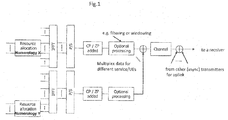
- Figure 1 shows a schematic overview of OFDM-based waveform in a transmitter where resource allocation for different users and/or different services is performed in the frequency domain.
- OFDM-based waveform in a transmitter where resource allocation for different users and/or different services is performed in the frequency domain.
- uplink transmission signals transmitted from multiple (possibly asynchronous) transmitters are received by a receiver.
- Different numerologies such as SC spacing may be used for different subbands.
- f 0 is the smallest SC spacing
- f 1 2 f 0
- f 2 2 f 1
- LCM least common multiple
- GCD greatest common divisor
- PRB physical source block
- PRB which is the smallest scheduling unit
- PRBs among all numerologies have nested relations.
- nesting means k consecutive PRBs for SC spacing f 0 cover the same frequency range as k/2 consecutive PRBs for SC spacing f 1 , the same frequency range as k/4 consecutive PRBs for SC spacing f 2 , etc.
- Figure 2 illustrates an example of the nested relations of PRBs among different numerologies.
- multiple numerologies may, for example, be time-domain or frequency-domain multiplexed and PRBs for different numerologies may be located on a fixed grid relative to each other.
- the PRB bandwidth is scaled with the SC spacing, e.g., when SC spacing is doubled, so is the PRB bandwidth. This results in the nested relations.
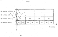
- Figure 3 illustrates an approach to place the SCs for different SC spacings from f 0 up to 8 f 0 based on Figure 2 .
- the number of subcarriers for PRBs at SC spacing f 0 is 6 for illustration.
- the resource grid for the SC spacing f 0 are partly indicated by the dashed vertical lines; for example, the leftmost vertical line labelled A indicates the SC center frequency of the lowest frequency within RB1 for the SC spacing f 0 .
- Figure 3 illustrates that SC center frequency corresponding to the lowest frequency within RB1 for all the SC spacings, i.e. numerologies, is located exactly on the same frequency as for the SC spacing f 0 .
- Figure 4 shows at the right hand side of RB1 for the SC spacing 2 f 0 , the rightmost SC is mapped on the second last resource grid, labelled B, of the SC spacing f 0 , instead of the last grid, labelled C, because only every other resource grid carries active SC for the SC spacing 2 f 0 .
- the reason for the left bias is that some multiples of 6 (right edge of a basic PRB in the example) are not multiples of 2n (position of subcarriers of straight-forward SC spacing for PRBs at SC spacing f n ).
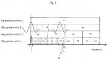
- FIG. 5 shows that the rightmost SC for the SC spacing 4 f 0 is mapped on the resource grid labelled B, which is biased to the left, i.e. towards lower frequencies in view of the resource grids C 1 , C 2 , C 3 of RB4 for the SC spacing f 0 .
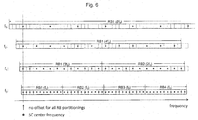
- Figure 6 illustrates the same mapping of the SC center frequencies in Figures 3 to 5 , but in another representation, where each circle represents the location of an active SC.
- the scenario in Figure 6 assumes that there are 12 subcarriers per PRBs at SC spacing f 0 .
- Figure 6 shows that the interference to neighbor PRBs are strongly biased to the left.
- the present invention intends to overcome the drawback of the prior art.
- This transmission method has the advantage that transmission can occur in resource blocks with mixed numerologies, e.g. different subcarrier spacings of resource blocks, so that diverse requirements can be met, e.g. to combat various inter carrier interferences, ICIs, with different mobility.
- the subcarrier centers within each resource block may be shifted by an offset, so as to control interference among subcarriers in neighboring physical resource blocks.
- subcarrier center frequencies of subcarrier spacing f n and subcarrier center frequencies of subcarrier spacing f n +1 are shifted by integer multiples of f n .
- said offset value for said subcarrier spacing f n is configurable for each n.
- said configurable offset value for said subcarrier spacing f n is chosen from a pre-defined set of values for each n.
- said configurable offset value for said subcarrier spacing f n is signaled from network to user equipment semi-statically or dynamically.
- the method is applicable to any waveform and any reference signal design that may be configured using the above aspects for defining the slot structure and physical resource elements.
- the offset value can be represented and configured in an efficient manner.
- an apparatus for transmitting a multicarrier signal over a frequency resource wherein
- the apparatus further comprises a module for performing the steps as defined in one of the embodiments of the invention.
- a multicarrier signal to be transmitted over a frequency resource, wherein
- Such a signal achieves the advantages with respect to a controlling interference among neighboring subcarriers that have been described for the above embodiments of the invention.
- Figure 7 shows an example offset value ( f n - f 0 )/2 for each SC spacing f n .
- all the subcarriers within each PRB for all the SC spacing are located symmetrically, which means that a subcarrier center in the SC spacing f n +1 has a frequency that lies in the middle between the respective subcarrier centers of subcarriers in the SC spacing f n That completely avoids unequal interference situations to neighbor PRBs and balanced BLER performance in neighbor PRBs can be expected.
- Figure 8 shows another example of offset value f n /2 for n > 0.
- all the SCs for SC spacing n > 0 are slightly biased to the higher frequency.
- the SC center frequencies for all the SC spacings are aligned with the resource grid of the base subcarrier spacing f 0 that has an advantage of efficient receiver processing.
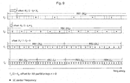
- Figure 9 shows a further example of offset value f n /2 - f 0 for n > 0. This is simply a shifted version of Figure 8 where all the SCs for SC spacing n > 0 are slightly biased to the lower frequency. The amount of the shift with respect to Figure 8 is equal to the base SC spacing f 0 .
- the SCs for the base SC spacing f 0 are slightly biased to the higher frequency.
- the f 0 subcarriers are shifted, namely by offset f 0 /2.
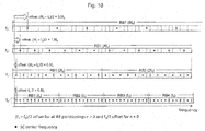
- Such a shift of the baseline SC locations may not be desired for compatibility reasons so that other embodiments which are also presented herein do not shift the baseline SC locations, i.e. the SC spacing f 0 .
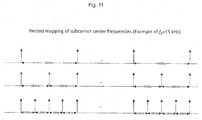
- Figure 11 illustrates the nested mapping of SC center frequencies, i.e., subcarriers are mapped on the subset/superset of those for subcarrier spacing of the base SC spacing f 0 in the nested manner in the frequency domain.
- SC center frequencies of SC spacing f n and SC center frequencies of SC spacing f n +1 are shifted by integer multiples of f n .
- offset values for SC spacing f n is selected to balance the interference to the left and right hand sides while satisfying the nested mapping of SC center frequencies for all the SC spacings.
- Figure 12 illustrates an example of 2 f 0 offset value for SC spacing of 4 f 0 when SC spacing up to 4 f 0 are supported in one system band. In contrast to no offset at all, which is shown in Figure 6 , interference to the left and right neighbor PRBs are more balanced while satisfying the nested SC center frequencies for all the SC spacings.
- Figure 13 shows another example of f 0 offset value for SC spacing of 2 f 0 and 4 f 0 when SC spacing up to 4 f 0 are supported in one system band.
- This is simply a mirrored version of Figure 12 .
- mirroring means that the locations of center frequencies of active SCs in Figure 13 , when mirrored on the frequency axis, corresponds to locations of center frequencies of active SCs in Figure 12 .
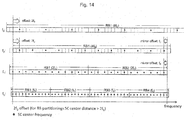
- Figure 14 , 15 , 16 , and 17 illustrate several offset values when SC spacing up to 8 f 0 are supported in one system band.
- Figure 14 introduces 2 f 0 offset value for the SC spacing of 4 f 0 and 8 f 0 .
- the details of the high end of the frequency spectrum for the 8 f 0 SC spacing are not shown in Figure 14 but are instead shown and detailed in Figure 15 , where only the f 0 SC spacing and the 8 f 0 SC spacing are shown.
- a mirror offset for each SC spacing f n can be determined as shown in Figure 14 .
- the mirror offset is the distance between the last subcarrier center (highest frequency) in the f n SC spacing and the last subcarrier center (highest frequency) in the last physical resource block of the f 0 SC spacing that is nested in the frequency range of the PRB at spacing f n .
- This distance can be determined based on integer/modulo arithmetic, the baseline subcarrier bandwidth f 0 , and the number of subcarriers per resource block.
- Figure 16 shows another offset value of 4 f 0 for the SC spacing of 8 f 0 while no offset for other SC spacing.
- the interference by the SC spacing 4 f 0 is more biased, but more balanced interference is achieved for the SC spacing 8 f 0 .
- the offset values in Figure 16 may lead to less critical interference than in Figure 14 .
- Figure 17 and Figure 18 are mirrored versions of the scenarios shown in Figure 14 and Figure 16 , respectively.
- offset value for SC spacing f n is configurable for each n and the configurable offset value is signaled from network to user equipment semi-statically or dynamically. This has the advantage that the network can choose an appropriate offset value by flexibly adapting to the resource usage. Thereby, offset values and their computations, according to the above, may be different for different users and/or different services.
- network can choose and signal offset values for the PRB or contiguous PRBs that result in less interference on that side where resource is already allocated.
- An extreme example is that no offset value as in Figures 4 , 5 , and 6 can be chosen if there is already allocated resource for a certain user or service on the right hand side (higher frequency), but not on the left hand side (lower frequency).
- the configurable offset value for SC spacing f n is chosen from pre-defined set of values for each n.
- Quantized indices can be defined for the pre-defined set and can be utilized for efficient signaling.
- the offset values for different numerologies have been defined in terms of f 0 or f n .
- alternative ways of expressing and specifying the offset value for different numerologies are described.
- offset values can be defined based on resource grids for SC spacing f 0 .
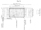
- An example of such a resource grid is shown in Figure 19 . More specifically, a multicarrier signal to be transmitted in a certain time slot is described by one or several resource grids of N RB N sc RB SCs and N symb symbols, where N sc RB denotes the number of SCs per physical resource block and N RB is the number of PRBs for SC spacing f 0 .
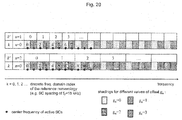
- the positions of the SC center frequencies for these two cases are illustrated with different shadings in the Figure 20 . It can be obtained from Figure 20 that the scenario for this first example is the same, i.e. same positions of SC center frequencies, as the one shown in Figure 8 , where the offset has been specified in terms of f n as f n /2 for n>0.
- the present invention has been described by adopting terminology and concepts from the LTE design. It should be clear to skilled person that the present invention can be applied to any multicarrier signal design with mixed numerologies.
- the present invention can be applicable for different link types, such as downlink, uplink, sidelink, etc.
- embodiments of the invention may be implemented by software or hardware or by a combination of both.
- a microprocessor e.g. a digital signal processor, controlled by a suitably programmed computer program.
Landscapes
- Engineering & Computer Science (AREA)
- Computer Networks & Wireless Communication (AREA)
- Signal Processing (AREA)
- Physics & Mathematics (AREA)
- Mathematical Physics (AREA)
- Mobile Radio Communication Systems (AREA)
Priority Applications (3)
| Application Number | Priority Date | Filing Date | Title |
|---|---|---|---|
| EP16190380.2A EP3300324A1 (de) | 2016-09-23 | 2016-09-23 | Verfahren und vorrichtung zur übertragung eines mehrträgersignals |
| JP2018510941A JP2018531539A (ja) | 2016-09-23 | 2017-09-21 | マルチキャリア信号を送信するための方法及び装置 |
| PCT/EP2017/073860 WO2018055017A1 (en) | 2016-09-23 | 2017-09-21 | Transmitting ofdm resource blocks with different subcarrier spacing |
Applications Claiming Priority (1)
| Application Number | Priority Date | Filing Date | Title |
|---|---|---|---|
| EP16190380.2A EP3300324A1 (de) | 2016-09-23 | 2016-09-23 | Verfahren und vorrichtung zur übertragung eines mehrträgersignals |
Publications (1)
| Publication Number | Publication Date |
|---|---|
| EP3300324A1 true EP3300324A1 (de) | 2018-03-28 |
Family
ID=57044865
Family Applications (1)
| Application Number | Title | Priority Date | Filing Date |
|---|---|---|---|
| EP16190380.2A Withdrawn EP3300324A1 (de) | 2016-09-23 | 2016-09-23 | Verfahren und vorrichtung zur übertragung eines mehrträgersignals |
Country Status (3)
| Country | Link |
|---|---|
| EP (1) | EP3300324A1 (de) |
| JP (1) | JP2018531539A (de) |
| WO (1) | WO2018055017A1 (de) |
Cited By (2)
| Publication number | Priority date | Publication date | Assignee | Title |
|---|---|---|---|---|
| US11206547B1 (en) | 2019-10-11 | 2021-12-21 | Sprint Spectrum L.P. | Contiguously clustering of resource allocation in response to near-frequency communication with different subcarrier spacing |
| WO2026026461A1 (zh) * | 2024-07-29 | 2026-02-05 | 华为技术有限公司 | 通信方法和相关装置 |
Families Citing this family (4)
| Publication number | Priority date | Publication date | Assignee | Title |
|---|---|---|---|---|
| KR20190120722A (ko) | 2018-04-16 | 2019-10-24 | 엘지전자 주식회사 | 무선 통신 시스템에서 신호를 생성하는 방법 및 장치 |
| CN110958700B (zh) * | 2018-09-27 | 2022-04-22 | 维沃移动通信有限公司 | 一种副链路资源确定方法和设备 |
| CN116321479A (zh) * | 2019-03-22 | 2023-06-23 | 上海朗帛通信技术有限公司 | 一种被用于无线通信的节点中的方法和装置 |
| CN117082624A (zh) * | 2022-05-05 | 2023-11-17 | 中兴通讯股份有限公司 | 数据的传输方法、装置、存储介质及电子装置 |
Family Cites Families (1)
| Publication number | Priority date | Publication date | Assignee | Title |
|---|---|---|---|---|
| CN101136894B (zh) * | 2007-03-23 | 2012-11-28 | 中兴通讯股份有限公司 | 可扩展的ofdm及ofdma带宽分配的方法和系统 |
-
2016
- 2016-09-23 EP EP16190380.2A patent/EP3300324A1/de not_active Withdrawn
-
2017
- 2017-09-21 JP JP2018510941A patent/JP2018531539A/ja active Pending
- 2017-09-21 WO PCT/EP2017/073860 patent/WO2018055017A1/en not_active Ceased
Non-Patent Citations (1)
| Title |
|---|
| QUALCOMM INCORPORATED: "Specification impact of OFDM filtering-windowing", vol. RAN WG1, no. Gothenburg, Sweden; 20160822 - 20160826, 13 August 2016 (2016-08-13), XP051142339, Retrieved from the Internet <URL:http://www.3gpp.org/ftp/tsg_ran/WG1_RL1/TSGR1_86/Docs/> [retrieved on 20160813] * |
Cited By (2)
| Publication number | Priority date | Publication date | Assignee | Title |
|---|---|---|---|---|
| US11206547B1 (en) | 2019-10-11 | 2021-12-21 | Sprint Spectrum L.P. | Contiguously clustering of resource allocation in response to near-frequency communication with different subcarrier spacing |
| WO2026026461A1 (zh) * | 2024-07-29 | 2026-02-05 | 华为技术有限公司 | 通信方法和相关装置 |
Also Published As
| Publication number | Publication date |
|---|---|
| JP2018531539A (ja) | 2018-10-25 |
| WO2018055017A1 (en) | 2018-03-29 |
Similar Documents
| Publication | Publication Date | Title |
|---|---|---|
| EP3300324A1 (de) | Verfahren und vorrichtung zur übertragung eines mehrträgersignals | |
| CN112040544B (zh) | 带宽利用的通讯设备和方法 | |
| US9942011B2 (en) | Wireless communication apparatus and the method thereof | |
| US8675570B2 (en) | Scalable OFDM and OFDMA bandwidth allocation in communication systems | |
| US10135663B2 (en) | FBMC signal transmitting method and receiving method, transmitter and receiver | |
| JP2018531539A6 (ja) | マルチキャリア信号を送信するための方法及び装置 | |
| US20110103333A1 (en) | Carrier aggregation | |
| US10536314B2 (en) | OFDMA apparatus and method thereof for performing OFDM based communication in wireless communication system | |
| KR20090125252A (ko) | 주파수 옵셋 보상 방법 | |
| CN107645464B (zh) | 多载波系统及多载波系统的数据调制、解调方法及装置 | |
| JP2010502078A (ja) | キャリア間干渉を相殺する伝送方法及び伝送装置 | |
| KR20160092837A (ko) | 다중 반송파 통신 시스템에서 전력을 제어하는 방법 및 장치 | |
| CN112204911A (zh) | 用于新无线电的数字方案选项 | |
| US8995374B2 (en) | Method for determining information which enable a mobile station to identify which resources are allocated to the mobile station | |
| JP2018527841A (ja) | マルチキャリア信号を送信するための方法及び装置 | |
| US10581546B2 (en) | Transmitter, transmission method, and receiver based on time-domain windows | |
| EP3358798A1 (de) | Empfänger, sender, kommunikationssystem zur teilbandkommunikation und verfahren zur teilbandkommunikation | |
| US10715366B2 (en) | Sub-band based composite digital time domain signal processing | |
| EP3599748B1 (de) | Symbolaufnahmeschema für dft-s-ofdm | |
| EP3282655A1 (de) | Verfahren und vorrichtung zur übertragung eines signals | |
| KR20080005821A (ko) | 통신 시스템에서 중심 주파수 설정 방법 | |
| HK40008447A (en) | Receiver, transmitter, communication system for subband communication and methods for subband communication |
Legal Events
| Date | Code | Title | Description |
|---|---|---|---|
| PUAI | Public reference made under article 153(3) epc to a published international application that has entered the european phase |
Free format text: ORIGINAL CODE: 0009012 |
|
| AK | Designated contracting states |
Kind code of ref document: A1 Designated state(s): AL AT BE BG CH CY CZ DE DK EE ES FI FR GB GR HR HU IE IS IT LI LT LU LV MC MK MT NL NO PL PT RO RS SE SI SK SM TR |
|
| AX | Request for extension of the european patent |
Extension state: BA ME |
|
| 17P | Request for examination filed |
Effective date: 20180611 |
|
| RBV | Designated contracting states (corrected) |
Designated state(s): AL AT BE BG CH CY CZ DE DK EE ES FI FR GB GR HR HU IE IS IT LI LT LU LV MC MK MT NL NO PL PT RO RS SE SI SK SM TR |
|
| GRAP | Despatch of communication of intention to grant a patent |
Free format text: ORIGINAL CODE: EPIDOSNIGR1 |
|
| INTG | Intention to grant announced |
Effective date: 20191112 |
|
| STAA | Information on the status of an ep patent application or granted ep patent |
Free format text: STATUS: THE APPLICATION IS DEEMED TO BE WITHDRAWN |
|
| 18D | Application deemed to be withdrawn |
Effective date: 20200603 |