EP3300454B1 - Appareil de cuisson à chauffage par induction - Google Patents
Appareil de cuisson à chauffage par induction Download PDFInfo
- Publication number
- EP3300454B1 EP3300454B1 EP17185052.2A EP17185052A EP3300454B1 EP 3300454 B1 EP3300454 B1 EP 3300454B1 EP 17185052 A EP17185052 A EP 17185052A EP 3300454 B1 EP3300454 B1 EP 3300454B1
- Authority
- EP
- European Patent Office
- Prior art keywords
- switch
- heating
- menu item
- display
- top plate
- Prior art date
- Legal status (The legal status is an assumption and is not a legal conclusion. Google has not performed a legal analysis and makes no representation as to the accuracy of the status listed.)
- Active
Links
Images


Classifications
-
- H—ELECTRICITY
- H05—ELECTRIC TECHNIQUES NOT OTHERWISE PROVIDED FOR
- H05B—ELECTRIC HEATING; ELECTRIC LIGHT SOURCES NOT OTHERWISE PROVIDED FOR; CIRCUIT ARRANGEMENTS FOR ELECTRIC LIGHT SOURCES, IN GENERAL
- H05B6/00—Heating by electric, magnetic or electromagnetic fields
- H05B6/02—Induction heating
- H05B6/06—Control, e.g. of temperature, of power
- H05B6/062—Control, e.g. of temperature, of power for cooking plates or the like
Definitions
- the present invention relates to an induction heating cooker.
- Patent Literature 1 proposes a conventional induction heating cooker having a configuration in which a plurality of switches disposed in an operation unit includes at least one switch assigned with a plurality of control commands. This configuration allows the number of switches disposed in a top plate to be reduced without a reduction in the number of control commands.
- Patent Literature 1 the conventional induction heating cooker proposed in Patent Literature 1 will be described using FIG. 7 .
- the conventional induction heating cooker includes top plate 201, a heating coil, operation unit 202, and a control unit.
- Top plate 201 is for placing a cooking container thereon.
- the heating coil is configured to generate an induction field, thereby induction-heating the cooking container.
- Operation unit 202 includes a plurality of switches assigned with their respective control commands. When such a switch of operation unit 202 is pressed, the control unit controls a high frequency current to be supplied to the heating coil, based on an inputted control command corresponding to the pressed switch.
- switches 202a, 202b, 202c, 202d, and 202e are disposed in the operation unit 202.
- Switch 202b is assigned with two control commands, that is, a control command to set/release a lock for enabling/disabling an operation and a control command to select cooking menu items, namely, deep-frying, water-boiling, and rice-cooking.
- Switch 202a corresponds to a heating on/off switch for controlling turn-on/off of heating.
- Switch 202c and switch 202d correspond to adjustment switches for increasing/decreasing a heating power and adjusting temperature.
- Switch 202e corresponds to a timer switch for setting a heating time.
- the conventional induction heating cooker is normally locked in a state of being turned on an electric power supply so as to disable the operation of switches 202a, 202c, 202d, and 202e. Therefore, switch 202b is assigned with a control command to unlock switches 202a and 202c to 202e, and functions as an unlocking switch. That is, when switch 202b is pressed in a state in which switches 202a, 202c, 202d, and 202e are locked, switches 202a, 202c, 202d, and 202e are unlocked.
- switch 202b is switched to function as a menu switch assigned with a control command to select a cooking menu item.
- switch 202b is configured that, every time switch 202b is pressed, a cooking menu item is sequentially selected from modes of "deep-fry", “water-boiling", and "rice-cooking".
- the induction heating cooker is configured so that, when switch 202a serving as a heating on/off switch is pressed in a state in which a predetermined cooking menu item is selected by the operation of switch 202b, heating is initiated in accordance with the selected predetermined cooking menu item.
- the above-mentioned induction heating cooker is configured so that heating menu items are sequentially selected in a single direction in accordance with the number of times of operation of a single switch for selecting a cooking menu item.
- a user needs to operate the switch two or more times. This causes an increase in the number of times of operations for selecting a cooking menu item, and thereby sometimes impairs the usability.
- the switch is pressed the wrong number of times past a heating menu item desired to be selected.
- the user in order to make a return to the heating menu item desired to be selected, the user needs to operate the switch for selecting a cooking menu item further two or more times to make a round to the heating menu item.
- the user needs to stop halfway the operation for selecting the heating menu item and try again the selection of the heating menu item from the beginning. This impairs usability in the selection of a cooking menu item.
- the conventional induction heating cooker needs to be provided with another switch (for example, switch 202e) for making valid a control command to select a cooking menu item from a plurality of control commands. This makes the configuration of the operation unit more complicated.
- the above-mentioned induction heating cooker includes three switches.
- a first switch is a switch assigned with a control command to increase a heating power for heating an object to be heated placed on a top plate and a control command to select a cooking menu item.
- a second switch is a switch assigned with a control command to decrease a heating power for heating an object to be heated placed on the top plate and a control command to select a cooking menu item.
- a third switch is a switch for switching between a control command to increase or decrease a heating power and a control command to select a cooking menu item. When the third switch for switching between the control commands is operated, the control command to select a cooking menu item becomes valid. With this configuration, a cooking menu item can be selected by the first switch for increasing a heating power or the second switch for decreasing a heating power.
- the above-mentioned induction heating cooker is configured to sequentially select a plurality of cooking menu items in different directions in accordance with the operation of the first switch for increasing a heating power and the second switch for decreasing a heating power.
- the above-mentioned induction heating cooker needs to be provided with a switch for making valid a control command to select a cooking menu item from a plurality of control commands. Accordingly, the configuration of the operation unit becomes more complicated. This impairs the usability of the induction heating cooker.
- EP 2 065 651 A2 describes an appliance which has a control unit and a user interface e.g. touch-screen, selecting a degree e.g. heating degree, from a number of degrees to adjust a successive adjustable operating parameter.
- the control unit is designed to use an allocation function for determining the operating parameter depending on the selected degree.
- the user interface includes an adjusting unit for changing the allocation function.
- the user interface has two buttons for incrementing and decrementing the degree.
- a memory unit e.g. ROM, stores a list of values used as a parameter of the function.
- WO 2011/128293 A2 describes a programmable user interaction control interface for household appliances such as ovens.
- the user interface comprises a display for displaying text and icons.
- the user interface further comprises control and selection buttons for navigation in a two dimensional menu structure. LED technology is used in order to lit up buttons as well as indicators.
- EP 2 161 966 A1 describes an induction heating device which includes an infrared ray sensor for detecting infrared rays radiated from a cooking container through a top plate, a light emitting device which is placed near the infrared ray sensor and emits light to the back surface of the top plate, and a heating control unit 8 which controls a high-frequency current through a heating coil for controlling the heating of the cooking container.
- the heating control unit has stopped the heating of the cooking container, and a predetermined time elapses at the heating-stopped state, the light emitting device is controlled to stop the light emission therefrom. This can improve durability of the light emitting device, which enables maintaining a function of clearly indicating a position at which the cooking container should be placed and a function of detecting failures in the infrared ray sensor, which are roles of the light emitting device.
- the invention is defined by the subject-matter of independent claim 1.
- the dependent claims are directed to advantageous embodiments.
- the present invention provides an induction heating cooker having a simplified operation unit and providing usability.
- the induction heating cooker includes a main body including a top plate on which an object to be heated is placed, and a heating coil disposed inside the main body and configured to induction-heat the object to be heated placed on the top plate.
- the induction heating cooker further includes an operation unit configured to set a heating condition for heating an object to be heated placed on the top plate, a display unit configured to display the heating condition set by the operation unit, and a control unit configured to control a high frequency current to be supplied to the heating coil, in accordance with the heating condition set by the operation unit.
- the operation unit includes a first switch configured to operate as a switch for selecting a heating menu item for heating an object to be heated placed on the top plate from a plurality of preset heating menu items and as a switch for increasing a heating power for heating an object to be heated placed on the top plate.
- the operation unit further includes a second switch configured to operate as a switch for selecting a heating menu item for heating an object to be heated placed on the top plate from a plurality of preset heating menu items and as a switch for decreasing a heating power for heating an object to be heated placed on the top plate.
- the control unit is configured to, when any heating menu item has not been set, set the first switch and the second switch as switches for selecting a heating menu item for heating an object to be heated placed on the top plate.
- control unit is configured to, when a heating menu item is set, set the first switch as a switch for increasing a heating power for heating an object to be heated placed on the top plate and set the second switch as a switch for decreasing a heating power for heating an object to be heated placed on the top plate.
- the control unit sets the first switch and the second switch as switches for selecting a heating menu item. Therefore, it is not necessary to dispose, in the operation unit, another switch for setting the first switch and the second switch as switches for selecting a heating menu item for an object to be heated. With this, a heating menu item for heating an object to be heated can be quickly selected by the first switch and the second switch. As a result, an induction heating cooker having a simplified operation unit and providing usability is achieved.
- a user can select a predetermined heating menu item from a plurality of heating menu items by operating the two switches, namely, the first switch and the second switch. Accordingly, for example, it can be configured such that the sequence of heating menu items selected one by one every operation of the first switch is the reverse of the sequence of heating menu items selected one by one every operation of the second switch.
- this configuration allows a larger reduction in the number of times of operation of the first switch or the second switch before a heating menu item is selected, compared with a configuration in which a heating menu item is selected with a single switch from a plurality of heating menu items. As a result, the usability of the induction heating cooker is improved.
- a heating menu item desired to be selected can be reversed by the operation of the other switch for making the selection in an opposite direction to the wrongly-operated switch.
- a heating menu desired to be selected can be selected by a smaller number of times of operation. As a result, usability is improved.
- control unit is configured to, when a heating menu item for heating an object to be heated placed on the top plate is set, set the first switch as a switch for increasing a heating power for heating an object to be heated.
- the control unit sets the second switch as a switch for decreasing a heating power for heating an object to be heated. Therefore, it is not necessary to dispose, in the operation unit, another switch for switching the first switch and the second switch to switches for increasing and decreasing a heating power for heating an object to be heated, respectively. That is, the control unit is capable of setting the first switch and the second switch as switches for increasing and decreasing a heating power for heating an object to be heated, respectively. This allows the configuration of the operation unit to be simplified, whereby an induction heating cooker providing usability is achieved.
- FIG. 1 is a schematic diagram of the induction heating cooker according to the present embodiment.
- FIG. 2 is a top view of a top plate according to the present embodiment.
- induction heating cooker 100 includes main body 3 including top plate 2 for placing object to be heated 1 thereon, heating coil 4 disposed inside main body 3, operation unit 7, display unit 8, and control unit 9.
- Heating coil 4 is configured to induction-heating object to be heated 1, such as a pan, which is placed on top plate 2.
- Operation unit 7 is configured to set a heating condition for object to be heated 1.
- Display unit 8 is configured to display, for example, the heating condition set by operation unit 7.
- Control unit 9 is configured to control, for example, a high frequency current to be supplied to heating coil 4 in accordance with the heating condition set by operation unit 7.
- Operation unit 7 and display unit 8 are disposed at the front portion of the top plate as illustrated in FIG. 2 .
- a plurality (three in the present embodiment) of heating units 11 indicating positions to place object to be heated 1 thereat is formed on the top face of top plate 2. Under each of the plurality of heating units 11, a corresponding one of heating coils 4 is disposed.
- Operation unit 7 includes power switch 10, first switch 5, second switch 6, and start switch 12.
- each of the switches When pressed by a user, each of the switches functions as follows.
- Power switch 10 causes induction heating cooker 100 to be turned on.
- First switch 5 operates as a switch for selecting, in a single direction, a heating menu item for heating object to be heated 1 placed on top plate 2 from a plurality of preset heating menu items. Furthermore, first switch 5 operates as a switch for increasing a heating power for heating object to be heated 1. Likewise, second switch 6 operates as a switch for selecting, in the reverse direction, a heating menu item for heating object to be heated 1 placed on top plate 2 from a plurality of preset heating menu items. In other words, second switch 6 is configured to select a heating menu item in an opposite (return) direction to that of first switch 5. Furthermore, second switch 6 operates as a switch for decreasing a heating power for heating object to be heated 1.
- Start switch 12 determines a heating menu item and a heating power selected by first switch 5 and second switch 6, and sets the heating menu item and the heating power in control unit 9 as heating conditions for heating object to be heated 1. That is, start switch 12 is used also as determination switch 7a. Determination switch 7a determines a selected heating menu item.
- first switch 5, second switch 6, and start switch 12 are disposed in each of heating units 11 formed in top plate 2.
- Display unit 8 is disposed at the back of operation unit 7, and displays, for example, heating menu items selected by first switch 5 and second switch 6. Furthermore, besides a heating menu item, display unit 8 displays heating conditions set by operation unit 7. For example, display unit 8 displays the level of heat for heating object to be heated 1 and a remaining time of a timer having a function of stopping heating after a lapse of a predetermined time period.
- heating menu items selected by first switch 5 and second switch 6 for example, "heating”, “deep-fry”, “grill”, and “water-boiling” are preset.
- Control unit 9 controls a high frequency current to be supplied to heating coil 4, based on information, such as a heating power set by first switch 5 and second switch 6, the temperature of object to be heated 1, and the time elapsed since the start of heating.
- control unit 9 controls a high frequency current to be supplied to heating coil 4.
- Induction heating cooker 100 is configured as described above.
- induction heating cooker 100 having the above-mentioned configuration will be described using FIG. 3A to FIG. 3F .
- heating is to heat object to be heated 1.
- Grill is to heat object to be heated 1, thereby grilling a food material accommodated in object to be heated 1.
- Deep-fry is to heat object to be heated 1, thereby frying a food material in a large amount of oil accommodated in object to be heated 1.
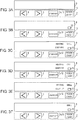
- FIG. 3A is a diagram illustrating a display state of display unit 8 before power is turned on.
- FIG. 3B is a diagram illustrating a display state of display unit 8 when power is turned on.
- FIG. 3C is a diagram illustrating a display state of display unit 8 in which, by operating the first switch in a state in which any heating menu item is not selected, "heating" is selected.
- FIG. 3D is a diagram illustrating a display state of display unit 8 in which, by operating the second switch in a state in which any heating menu item is not selected, "deep-fry" is selected.
- FIG. 3A is a diagram illustrating a display state of display unit 8 before power is turned on.
- FIG. 3B is a diagram illustrating a display state of display unit 8 when power is turned on.
- FIG. 3C is a diagram illustrating a display state of display unit 8 in which, by operating the first switch in a state in which any heating menu item is not selected, "heating" is selected.
- FIG. 3E is a diagram illustrating a display state of display unit 8 in which, by operating the first switch or the second switch in a state in which any heating menu item is not selected, "grill" is selected.
- FIG. 3F is a diagram illustrating a display state of display unit 8 when "grill" is finally set as a heating menu item.
- a user places object to be heated 1 at heating unit 11 on top plate 2 as illustrated in FIG. 1 and FIG. 2 .
- the user operates power switch 10 disposed in operation unit 7.
- electric power is supplied to each of the switches disposed in operation unit 7 and supplied to display unit 8. This leads to a state in which the user can set, for example, a heating menu item and heating conditions for object to be heated 1 via operation unit 7.
- control unit 9 turns on power indication light 13 disposed in display unit 8 to inform the user that power switch 10 is on, as illustrated in FIG. 3B .
- a heating menu item for heating object to be heated 1 placed on top plate 2 has not been set.
- control unit 9 automatically sets first switch 5 and second switch 6 as switches for selecting a heating menu item for heating object to be heated 1.
- control unit 9 causes display unit 8 to display all or some of heating menu items selectable by first switch 5 and second switch 6. Furthermore, control unit 9 sequentially causes heating menu items sequentially selected by a user's pressing operation to flash on and off. This flashing allows the user to recognize which heating menu item is in a state of being selected.
- control unit 9 causes display unit 8 to display all the preset heating menu items, namely, "heating", “grill”, and "deep-fry”. Then, control unit 9 causes the display of "heating" in display unit 8, selected by the user, to flash on and off.
- control unit 9 causes display unit 8 to display all the preset heating menu items, namely, "heating”, “grill”, and "deep-fry”. Then, control unit 9 causes the display of "deep-fry” in display unit 8, selected by the user, to flash on and off.
- a description is given by taking as an example a method of identification of a heating menu item selected by a user by causing the item to flash on and off, but a method of identification is not limited to this.
- a configuration for identifying a heating menu item may be such that a heating menu item selected by a user is displayed at a higher brightness than that of a heating menu item not selected by the user.
- a configuration may be such that a heating menu item selected by a user is displayed in a different manner from a heating menu item not selected by the user. That is, any identification method may be employed as long as the method enables a selected heating menu item to be identified.
- control unit 9 causes the shifted heating menu item to flash on and off in display unit 8.
- control unit 9 causes the display of "heating” to stop flashing on and off and causes the display of "grill” in display unit 8 to flash on and off.
- control unit 9 causes the display of "grill” to stop flashing on and off and causes the display of "deep-fry” in display unit 8 to flash on and off.
- control unit 9 causes the display of "deep-fry” to stop flashing on and off and causes the display of "heating" in display unit 8 to flash on and off.
- the induction heating cooker according to the present embodiment is configured such that, every time first switch 5 is operated, a plurality of the heating menu items is shifted in a single direction and selected sequentially.
- the induction heating cooker is configured such that, every time second switch 6 is operated, the plurality of the heating menu items is shifted in the opposite direction to that in the operation of first switch 5 and selected sequentially.
- menu item J is selected by a shift from menu item B, for example, when the selection is made in a clockwise direction by first switch 5, the selection needs eight operations. However, when the selection is made in a counter-clockwise direction by second switch 6, menu item J can be selected in two operations.
- second switch 6 in a state in which menu item F is selected, thereby making a counter-clockwise return to the previous heating menu item to select menu item E.
- second switch 6 allows the return to menu item E, whereby the target heating menu item is selected.
- control unit 9 starts heating object to be heated 1 by a heating operation corresponding to the set heating menu item.
- control unit 9 causes display unit 8 to display only the heating menu item set by the user with the item flashing on and off. With this, the user is informed of which heating menu item the user has set.
- control unit 9 automatically changes functions of first switch 5 and second switch 6 to the following functions in accordance with the heating menu item set by a user.
- control unit 9 causes display unit 8 to display information on a heating power for heating object to be heated 1. Furthermore, control unit 9 sets first switch 5 as a switch for increasing a heating power, and sets second switch 6 as a switch for decreasing a heating power. Then, in accordance with the operation of first switch 5 or second switch 6, control unit 9 controls a high frequency current to be supplied to heating coil 4 so as to increase or decrease a heating power for heating object to be heated 1.
- control unit 9 causes display unit 8 to display a target temperature for heating object to be heated 1. Furthermore, control unit 9 sets first switch 5 as a switch for increasing a target temperature for object to be heated 1, and sets second switch 6 as a switch for decreasing a target temperature for object to be heated 1. Then, in accordance with the operation of first switch 5 or second switch 6, control unit 9 controls a high frequency current to be supplied to heating coil 4 so as to increase or decrease the target temperature for object to be heated 1.
- first switch 5 and second switch 6 are set again in accordance with a heating menu item set by a user and a set state.
- the setting is such that the operation of first switch 5 causes a set value to change to be larger.
- the setting is such that the operation of second switch 6 causes a set value to change to be smaller.
- the directions of change in set values of first switch 5 and second switch 6 may be opposite to the above-mentioned directions.
- control unit 9 sets first switch 5 and second switch 6 as switches for selecting a heating menu item.
- control unit 9 sets first switch 5 and second switch 6 as switches for selecting a heating menu item.
- another switch for setting first switch 5 and second switch 6 as switches for selecting a heating menu item can be selected by first switch 5 and second switch 6.
- a predetermined heating menu item is selected from a plurality of heating menu items.
- it is configured such that the sequence of heating menu items selected one by one every operation of first switch 5 is the reverse of the sequence of heating menu items selected one by one every operation of second switch 6. Therefore, even in the case where there are many heating menu items, this configuration allows a larger reduction in the number of times of operation of first switch 5 or second switch 6 before a heating menu item is selected, compared with a configuration in which a heating menu item is selected by a single switch. Thus, the usability of induction heating cooker 100 is improved.
- first switch 5 or second switch 6 is pressed the wrong number of times past a heating menu item desired to be selected, the operation of the other switch for making the selection in an opposite direction to the operated switch allows a return to the heating menu item.
- a heating menu desired to be selected can be selected by a smaller number of times of operation. As a result, the operability of induction heating cooker 100 is improved.
- control unit 9 is configured to, when a heating menu item for heating object to be heated 1 is set, change the functions of first switch 5 and second switch 6 in accordance with the heating menu item set by a user and a set state. Hence, there is no need to dispose, in operation unit 7, a plurality of switches each for a corresponding one of functions. In other words, control unit 9 can change a set value for each of the functions of first switch 5 and second switch 6. This allows the configuration of operation unit 7 to be simplified, whereby the operability of induction heating cooker 100 is improved.
- control unit 9 is configured to, when a heating menu item for heating object to be heated 1 is set, set first switch 5 as a switch for increasing a heating power and set second switch 6 as a switch for decreasing a heating power.
- control unit 9 there is no need to dispose, in operation unit 7, another switch for setting first switch 5 and second switch 6 so as to function as switches for increasing and decreasing a heating power, respectively. That is, a heating power for heating object to be heated 1 can be increased and decreased only by first switch 5 and second switch 6, respectively.
- This allows the configuration of operation unit 7 to be simplified, whereby induction heating cooker 100 having excellent operability can be achieved.
- control unit 9 automatically causes first switch 5 and second switch 6 to operate as switches for selecting a heating menu item
- the present invention is not limited to this configuration. Any configuration may be employed as long as the configuration causes first switch 5 and second switch 6 to, in a state in which any heating menu item is not set, operate as switches for selecting a heating menu item.
- it may be configured such that, when a user operates any one of a plurality of switches disposed in operation unit 7, control unit 9 automatically causes first switch 5 and second switch 6 to operate as switches for selecting a heating menu item.
- the above-mentioned one switch is any one of first switch 5, second switch 6, and start switch 12, for example.
- Embodiment 2 of the present invention will be described using FIG. 4 .
- the same or equivalent constituents as those in the above-mentioned Embodiment 1 are assigned with the same reference numerals, and a duplicate description thereof will be omitted.
- FIG. 4 is a flowchart illustrating the selection of a heating menu item in Embodiment 2.
- the induction heating cooker according to the present embodiment is configured such that, first, when first switch 5 or second switch 6 is operated in a state in which any heating menu item for heating object to be heated 1 is not set, a preset first heating menu item is selected. Furthermore, the induction heating cooker is configured such that, when first switch 5 or second switch 6 is operated in a state in which the first heating menu item is set, a heating menu item different depending on the operated switch is selected. In terms of the above-mentioned configuration, the induction heating cooker according to the present embodiment differs from the induction heating cooker according to Embodiment 1.
- control unit 9 detects whether or not power switch 10 has been operated (step S101). If power switch 10 has not been operated (NO at step S101), the power source of induction heating cooker 100 is operated so that induction heating cooker 100 is put on standby until the operation of power switch 10 is detected.
- control unit 9 determines whether or not first switch 5 or second switch 6 has been operated (step S102). That is, if a user operates power switch 10 to turn on induction heating cooker 100 (YES at step S101), control unit 9 detects whether or not first switch 5 or second switch 6 has been operated (step S102).
- the present embodiment it is configured such that, when a user operates first switch 5 or second switch 6 in a state in which induction heating cooker 100 is turned on and any heating menu item is not set, regardless of which switch is operated, the same first heating menu item is selected.
- control unit 9 detects that first switch 5 or second switch 6 has not been operated (NO at step S102)
- the process returns to step S102. Then, induction heating cooker 100 is put on standby until first switch 5 or second switch 6 is operated.
- heating which is a frequently-used heating menu item, is set as a first heating menu item.
- any heating menu item may be set as a second or third heating menu item as long as a second heating menu item and a third heating menu item are different from each other.
- a second heating menu item and a third heating menu item there may be set arbitrary heating menu items selected from a plurality of heating menu items preset in induction heating cooker 100, heating menu items determined by a questionnaire survey addressed to users, and heating menu items intended to appeal to users.
- a plurality of heating menu items is disposed in a predetermined sequence.
- the direction of selection of a heating menu item by the operation of first switch 5 is configured to be different from (opposite to) the direction of selection of a heating menu item by the operation of second switch 6. That is, an improvement in the sequence or direction of selection of a heating menu item leads to a further improvement in the operability of induction heating cooker 100.
- the induction heating cooker according to the present embodiment is configured such that, when first switch 5 is operated in a state in which the first heating menu item is selected, a preset second heating menu item is selected. Furthermore, the induction heating cooker is configured such that, when second switch 6 is operated in a state in which the first heating menu item is selected, a preset third heating menu item is selected. That is, the induction heating cooker is configured such that, when first switch 5 or second switch 6 is operated after the first heating menu item is selected, a heating menu item different from the first heating menu item can be selected in accordance with the operated switch. Therefore, the number of times of operation of first switch 5 or second switch 6 before a user selects a heating menu item desired to be selected can be reduced. Thus, the operability of the induction heating cooker is improved.
- first display 14 may be in an arbitrary form as long as the form allows a user to recognize that first switch 5 and second switch 6 are switches for selecting a heating menu item.
- the display may be made by enclosing characters such as "menu" with a figure such as a square as illustrated in FIG. 5 .
- the display may be composed only of characters such as "menu”.
- the form of first display 14 is not limited to a particular form as long as the form is recognizable by a user. With this, a user can easily recognize that first switch 5 and second switch 6 are in an operating state as switches for selecting a heating menu item. Thus, the user can easily identify the operating state of first switch 5 and second switch 6. As a result, the usability of induction heating cooker 100 is improved.
- first switch 5 and second switch 6 function as not switches for selecting a heating menu item, but switches for operating other functions
- first display 14 is preferably not displayed. This prevents a user from misunderstanding the functions of first switch 5 and second switch 6. As a result, an unnecessary operation caused by the misunderstanding is prevented, and the usability of the induction heating cooker is further improved.
- FIG. 6 is a schematic diagram of the display unit, the diagram illustrating a state in which a modification of first display 14 according to Embodiment 4 is displayed.
- control unit 9 causes display unit 8 to display, via first display 14, that first switch 5 and second switch 6 are in an operating state as switches for selecting a heating menu item, and thereby to inform a user of the state.
- first display 14 is disposed such that at least part of first display 14 is positioned in the range of the left-right width between first switch 5 and second switch 6, both inclusive, illustrated in FIG. 6 .
- first display 14 is composed of a combination of two inverted triangles and characters such as "menu" disposed between the two inverted triangles.
- first display 14 is displayed in display unit 8 such that each of the apexes of the two inverted triangles is positioned at the top of a corresponding one of first switch 5 and second switch 6. This allows a user to appropriately recognize the correspondence.
- the induction heating cooker includes a main body including a top plate on which an object to be heated is placed, and a heating coil disposed inside the main body and configured to induction-heat the object to be heated placed on the top plate.
- the induction heating cooker further includes an operation unit configured to set a heating condition for heating the object to be heated placed on the top plate, a display unit configured to display the heating condition set by the operation unit, and a control unit configured to control a high frequency current to be supplied to the heating coil, in accordance with the heating condition set by the operation unit.
- control unit is configured to, when a heating menu item is set (determined), set the first switch as a switch for increasing a heating power for heating an object to be heated placed on the top plate and set the second switch as a switch for decreasing a heating power for heating an object to be heated placed on the top plate.
- the control unit sets the first switch and the second switch as switches for selecting a heating menu item. Therefore, it is not necessary to dispose, in the operation unit, another switch for setting the first switch and the second switch as switches for selecting a heating menu item for an object to be heated. With this, a heating menu item for heating an object to be heated can be quickly selected by the first switch and the second switch. As a result, an induction heating cooker having a simplified operation unit and providing usability is achieved.
- a heating menu desired to be selected can be selected by a smaller number of times of operation. As a result, usability is improved.
- control unit is configured to, when a heating menu item for heating an object to be heated placed on the top plate is set, set the first switch as a switch for increasing a heating power for heating an object to be heated.
- the control unit sets the second switch as a switch for decreasing a heating power for heating an object to be heated. Therefore, it is not necessary to dispose, in the operation unit, another switch for switching the first switch and the second switch to switches for increasing and decreasing a heating power for heating an object to be heated, respectively. That is, the control unit is capable of setting the first switch and the second switch as switches for increasing and decreasing a heating power for heating an object to be heated, respectively. This allows the configuration of the operation unit to be simplified, whereby an induction heating cooker providing usability is achieved.
- the induction heating cooker according to the present invention may be configured such that, when the first switch or the second switch is operated in a state in which any heating menu item is not set, a preset first heating menu item is selected.
- This configuration allows, for example, a highly-frequently-used heating menu item to be preset as the first heating menu item out of a plurality of heating menu items.
- a highly-frequently-used heating menu item can be selected by the first operation of the first switch or the second switch.
- the usability of the induction heating cooker is improved.
- the induction heating cooker according to the present invention may be configured such that, when the first switch is operated in a state in which the first heating menu item is selected, a preset second heating menu item is selected, and when the second switch is operated in a state in which the first heating menu item is selected, a preset third heating menu item is selected.
- the induction heating cooker according to the present invention may be configured such that the first switch and the second switch are disposed to adjacent to each other, and when the first switch and the second switch are in an operating state as switches for selecting a heating menu item, the display unit displays a first display for informing that a heating menu item is selectable by the first switch and the second switch.
- the induction heating cooker according to the present invention may be configured such that the first display is disposed at a position of the display unit, the position corresponding to the first switch and the second switch disposed to adjacent to each other.
- the induction heating cooker according to the present invention may be configured such that the first display is displayed so as to have at least part of the first display disposed at a position corresponding to the range of the left-right width between the first switch and the second switch, both inclusive.
- an expression for prompting the operation of the switches can be made with a "figure”
- an expression for indicating that the first switch and the second switch have been set as switches for selecting a heating menu item can be made with a "character”.
- a state in which the first switch and the second switch are operable can be expressed in various ways. With this, the user can more easily identify that the first switch and the second switch are in an operating state as switches for selecting a heating menu item. As a result, the usability of the induction heating cooker is further improved.
- the induction heating cooker according to the present invention may be configured such that, with a combination of a plurality of figures and a character disposed between the figures, the first display displays a state in which the first switch and the second switch are in an operable state.
Landscapes
- Physics & Mathematics (AREA)
- Electromagnetism (AREA)
- Induction Heating Cooking Devices (AREA)
Claims (8)
- Cuisinière à induction (100) comportant :un corps principal (3) comprenant une plaque supérieure (2) sur laquelle est placé un objet (1) à chauffer ;une bobine de chauffage (4) disposée à l'intérieur du corps principal (3) et configurée pour chauffer par induction l'objet (1) à chauffer placé sur la plaque supérieure (2) ;une unité de commande (7) configurée pour définir une condition de chauffage pour chauffer l'objet (1) à chauffer placé sur la plaque supérieure (2) ;une unité d'affichage (8) configurée pour afficher la condition de chauffage définie par l'unité de commande (7) ; etune unité de contrôle (9) configurée pour contrôler un courant haute fréquence à fournir à la bobine de chauffage (4) conformément à la condition de chauffage définie par l'unité de commande (7),où l'unité de commande (7) comprend :un premier commutateur (5) configuré pour servir de commutateur pour sélectionner un élément de menu de chauffage pour chauffer un objet (1) à chauffer placé sur la plaque supérieure (2) parmi une pluralité d'éléments de menu de chauffage prédéfinis, et de commutateur pour augmenter une puissance de chauffe pour chauffer un objet (1) à chauffer placé sur la plaque supérieure (2) ; etun second commutateur (6) configuré pour servir de commutateur pour sélectionner un élément de menu de chauffage pour chauffer un objet (1) à chauffer placé sur la plaque supérieure (2) parmi une pluralité d'éléments de menu de chauffage prédéfinis, et de commutateur pour réduire une puissance de chauffe pour chauffer un objet (1) à chauffer placé sur la plaque supérieure (2) ;caractérisée en ce que :
l'unité de contrôle (9) est configuréelorsque l'élément de menu de chauffage n'a pas été défini, pour régler le premier commutateur (5) et le second commutateur (6) en tant que commutateurs pour sélectionner un élément de menu de chauffage pour chauffer un objet (1) à chauffer placé sur la plaque supérieure (2), etlorsque l'élément de menu de chauffage a été défini, pour régler le premier commutateur (5) en tant que commutateur pour augmenter une puissance de chauffe pour chauffer un objet (1) à chauffer placé sur la plaque supérieure (2), et régler le second commutateur (6) en tant que commutateur pour réduire une puissance de chauffe pour chauffer un objet (1) à chauffer placé sur la plaque supérieure (2). - Cuisinière à induction (100) selon la revendication 1, dans laquelle, quand le premier commutateur (5) ou le second commutateur (6) est actionné dans un état dans lequel l'élément de menu de chauffage n'est pas défini, un premier élément de menu de chauffage prédéfini est sélectionné.
- Cuisinière à induction (100) selon la revendication 2,
dans laquelle, quand le premier commutateur (5) est actionné dans un état dans lequel le premier élément de menu de chauffage est sélectionné, un second élément de menu de chauffage prédéfini est sélectionné, et
dans laquelle, quand le second commutateur (6) est actionné dans un état dans lequel le premier élément de menu de chauffage est sélectionné, un troisième élément de menu de chauffage prédéfini est sélectionné. - Cuisinière à induction (100) selon la revendication 1,
dans laquelle le premier commutateur (5) et le second commutateur (6) sont disposés de manière à être adjacents l'un à l'autre, et
dans laquelle, quand le premier commutateur (5) et le second commutateur (6) fonctionnent en tant que commutateurs pour sélectionner l'élément de menu de chauffage, l'unité d'affichage (8) affiche un premier écran d'affichage (14) indiquant que l'élément de menu de chauffage peut être sélectionné par le premier commutateur (5) et le second commutateur (6). - Cuisinière à induction (100) selon la revendication 4, dans laquelle le premier écran d'affichage (14) est disposé en une position de l'unité d'affichage (8) correspondant au premier commutateur (5) et au second commutateur (6) disposés de manière adjacente l'un à l'autre.
- Cuisinière à induction (100) selon la revendication 5, dans laquelle le premier écran d'affichage (14) est affiché de manière à ce qu'au moins une partie du premier écran d'affichage (14) soit disposée en une position correspondant à un ordre de grandeur d'une largeur gauche droite entre le premier commutateur (5) et le second commutateur (6) inclus, disposés de manière adjacente l'un à l'autre.
- Cuisinière à induction (100) selon la revendication 4, dans laquelle le premier écran d'affichage (14) indique que le premier commutateur (5) et le second commutateur (6) sont dans un état d'actionnement au moyen d'une combinaison d'une lettre et d'un chiffre.
- Cuisinière à induction (100) selon la revendication 4, dans laquelle le premier écran d'affichage (14) indique que le premier commutateur (5) et le second commutateur (6) sont dans un état d'actionnement au moyen d'une combinaison d'une pluralité de chiffres et d'une lettre disposée entre les chiffres.
Applications Claiming Priority (1)
| Application Number | Priority Date | Filing Date | Title |
|---|---|---|---|
| JP2016183572A JP6850960B2 (ja) | 2016-09-21 | 2016-09-21 | 誘導加熱調理器 |
Publications (2)
| Publication Number | Publication Date |
|---|---|
| EP3300454A1 EP3300454A1 (fr) | 2018-03-28 |
| EP3300454B1 true EP3300454B1 (fr) | 2018-11-07 |
Family
ID=59558307
Family Applications (1)
| Application Number | Title | Priority Date | Filing Date |
|---|---|---|---|
| EP17185052.2A Active EP3300454B1 (fr) | 2016-09-21 | 2017-08-07 | Appareil de cuisson à chauffage par induction |
Country Status (2)
| Country | Link |
|---|---|
| EP (1) | EP3300454B1 (fr) |
| JP (1) | JP6850960B2 (fr) |
Family Cites Families (6)
| Publication number | Priority date | Publication date | Assignee | Title |
|---|---|---|---|---|
| JP5270848B2 (ja) | 2007-03-01 | 2013-08-21 | パナソニック株式会社 | 誘導加熱調理器 |
| EP2161966B1 (fr) * | 2007-06-22 | 2013-08-14 | Panasonic Corporation | Appareil de cuisson à induction |
| JP5194710B2 (ja) * | 2007-10-22 | 2013-05-08 | パナソニック株式会社 | 加熱調理器 |
| ES2332970B1 (es) * | 2007-11-28 | 2011-01-17 | Bsh Electrodomesticos España, S.A. | Aparato domestico con al menos una unidad de potencia. |
| JP5316484B2 (ja) * | 2009-09-10 | 2013-10-16 | 三菱電機株式会社 | 誘導加熱調理器、誘導加熱調理器の制御方法 |
| AU2011240145B2 (en) * | 2010-04-12 | 2016-03-17 | Aktiebolaget Electrolux | A control interface for household appliances |
-
2016
- 2016-09-21 JP JP2016183572A patent/JP6850960B2/ja active Active
-
2017
- 2017-08-07 EP EP17185052.2A patent/EP3300454B1/fr active Active
Non-Patent Citations (1)
| Title |
|---|
| None * |
Also Published As
| Publication number | Publication date |
|---|---|
| JP6850960B2 (ja) | 2021-03-31 |
| JP2018049712A (ja) | 2018-03-29 |
| EP3300454A1 (fr) | 2018-03-28 |
Similar Documents
| Publication | Publication Date | Title |
|---|---|---|
| KR101151519B1 (ko) | 가열 조리기 | |
| JP5368986B2 (ja) | 加熱調理器 | |
| JP5051318B2 (ja) | 誘導加熱調理器 | |
| JP6227162B2 (ja) | 誘導加熱調理器 | |
| CN110691943A (zh) | 灶具的用户界面 | |
| US6940049B2 (en) | Heating element temperature control for a cooking appliance | |
| CN114501710B (zh) | 感应加热烹调器以及计算机可读取的记录介质 | |
| EP3300454B1 (fr) | Appareil de cuisson à chauffage par induction | |
| JP5223782B2 (ja) | 誘導加熱装置 | |
| EP3473935B1 (fr) | Appareil de cuisson avec fonction de grille sélectionnable par l'utilisateur | |
| JP6909956B2 (ja) | 誘導加熱調理器 | |
| KR102914279B1 (ko) | 가전 기기의 제어 장치 및 가전 기기의 제어 방법 | |
| JP6897419B2 (ja) | 表示・操作部を具える調理器 | |
| JP4879564B2 (ja) | 加熱調理器 | |
| JP2005158329A (ja) | 多口加熱調理器 | |
| JP4613675B2 (ja) | 誘導加熱調理器 | |
| CN114585125B (zh) | 感应加热烹调器以及计算机程序的存储介质 | |
| JP5680158B2 (ja) | 加熱調理器 | |
| JP2011023318A (ja) | 加熱調理器 | |
| JP5948604B2 (ja) | 加熱調理器 | |
| JP2024101585A (ja) | 加熱調理器及び加熱調理システム | |
| CN113939690A (zh) | 用于家用电器的控制单元和用于控制家用电器的方法 | |
| KR101468044B1 (ko) | 보온 예약 기능을 구비한 전기 보온 밥솥 및 전기 보온 밥솥의 보온 기능 예약 방법 | |
| JP2022084300A (ja) | 誘導加熱調理器及びコンピュータプログラム | |
| JPWO2014171126A1 (ja) | 加熱調理器 |
Legal Events
| Date | Code | Title | Description |
|---|---|---|---|
| PUAI | Public reference made under article 153(3) epc to a published international application that has entered the european phase |
Free format text: ORIGINAL CODE: 0009012 |
|
| STAA | Information on the status of an ep patent application or granted ep patent |
Free format text: STATUS: THE APPLICATION HAS BEEN PUBLISHED |
|
| AK | Designated contracting states |
Kind code of ref document: A1 Designated state(s): AL AT BE BG CH CY CZ DE DK EE ES FI FR GB GR HR HU IE IS IT LI LT LU LV MC MK MT NL NO PL PT RO RS SE SI SK SM TR |
|
| AX | Request for extension of the european patent |
Extension state: BA ME |
|
| STAA | Information on the status of an ep patent application or granted ep patent |
Free format text: STATUS: REQUEST FOR EXAMINATION WAS MADE |
|
| 17P | Request for examination filed |
Effective date: 20180514 |
|
| RBV | Designated contracting states (corrected) |
Designated state(s): AL AT BE BG CH CY CZ DE DK EE ES FI FR GB GR HR HU IE IS IT LI LT LU LV MC MK MT NL NO PL PT RO RS SE SI SK SM TR |
|
| GRAP | Despatch of communication of intention to grant a patent |
Free format text: ORIGINAL CODE: EPIDOSNIGR1 |
|
| STAA | Information on the status of an ep patent application or granted ep patent |
Free format text: STATUS: GRANT OF PATENT IS INTENDED |
|
| INTG | Intention to grant announced |
Effective date: 20180627 |
|
| GRAS | Grant fee paid |
Free format text: ORIGINAL CODE: EPIDOSNIGR3 |
|
| GRAA | (expected) grant |
Free format text: ORIGINAL CODE: 0009210 |
|
| STAA | Information on the status of an ep patent application or granted ep patent |
Free format text: STATUS: THE PATENT HAS BEEN GRANTED |
|
| AK | Designated contracting states |
Kind code of ref document: B1 Designated state(s): AL AT BE BG CH CY CZ DE DK EE ES FI FR GB GR HR HU IE IS IT LI LT LU LV MC MK MT NL NO PL PT RO RS SE SI SK SM TR |
|
| REG | Reference to a national code |
Ref country code: GB Ref legal event code: FG4D |
|
| REG | Reference to a national code |
Ref country code: CH Ref legal event code: EP Ref country code: AT Ref legal event code: REF Ref document number: 1063665 Country of ref document: AT Kind code of ref document: T Effective date: 20181115 |
|
| REG | Reference to a national code |
Ref country code: DE Ref legal event code: R096 Ref document number: 602017000835 Country of ref document: DE |
|
| REG | Reference to a national code |
Ref country code: IE Ref legal event code: FG4D |
|
| REG | Reference to a national code |
Ref country code: NL Ref legal event code: MP Effective date: 20181107 |
|
| REG | Reference to a national code |
Ref country code: LT Ref legal event code: MG4D |
|
| REG | Reference to a national code |
Ref country code: AT Ref legal event code: MK05 Ref document number: 1063665 Country of ref document: AT Kind code of ref document: T Effective date: 20181107 |
|
| PG25 | Lapsed in a contracting state [announced via postgrant information from national office to epo] |
Ref country code: LT Free format text: LAPSE BECAUSE OF FAILURE TO SUBMIT A TRANSLATION OF THE DESCRIPTION OR TO PAY THE FEE WITHIN THE PRESCRIBED TIME-LIMIT Effective date: 20181107 Ref country code: FI Free format text: LAPSE BECAUSE OF FAILURE TO SUBMIT A TRANSLATION OF THE DESCRIPTION OR TO PAY THE FEE WITHIN THE PRESCRIBED TIME-LIMIT Effective date: 20181107 Ref country code: HR Free format text: LAPSE BECAUSE OF FAILURE TO SUBMIT A TRANSLATION OF THE DESCRIPTION OR TO PAY THE FEE WITHIN THE PRESCRIBED TIME-LIMIT Effective date: 20181107 Ref country code: BG Free format text: LAPSE BECAUSE OF FAILURE TO SUBMIT A TRANSLATION OF THE DESCRIPTION OR TO PAY THE FEE WITHIN THE PRESCRIBED TIME-LIMIT Effective date: 20190207 Ref country code: AT Free format text: LAPSE BECAUSE OF FAILURE TO SUBMIT A TRANSLATION OF THE DESCRIPTION OR TO PAY THE FEE WITHIN THE PRESCRIBED TIME-LIMIT Effective date: 20181107 Ref country code: IS Free format text: LAPSE BECAUSE OF FAILURE TO SUBMIT A TRANSLATION OF THE DESCRIPTION OR TO PAY THE FEE WITHIN THE PRESCRIBED TIME-LIMIT Effective date: 20190307 Ref country code: NO Free format text: LAPSE BECAUSE OF FAILURE TO SUBMIT A TRANSLATION OF THE DESCRIPTION OR TO PAY THE FEE WITHIN THE PRESCRIBED TIME-LIMIT Effective date: 20190207 Ref country code: ES Free format text: LAPSE BECAUSE OF FAILURE TO SUBMIT A TRANSLATION OF THE DESCRIPTION OR TO PAY THE FEE WITHIN THE PRESCRIBED TIME-LIMIT Effective date: 20181107 Ref country code: LV Free format text: LAPSE BECAUSE OF FAILURE TO SUBMIT A TRANSLATION OF THE DESCRIPTION OR TO PAY THE FEE WITHIN THE PRESCRIBED TIME-LIMIT Effective date: 20181107 |
|
| PG25 | Lapsed in a contracting state [announced via postgrant information from national office to epo] |
Ref country code: AL Free format text: LAPSE BECAUSE OF FAILURE TO SUBMIT A TRANSLATION OF THE DESCRIPTION OR TO PAY THE FEE WITHIN THE PRESCRIBED TIME-LIMIT Effective date: 20181107 Ref country code: SE Free format text: LAPSE BECAUSE OF FAILURE TO SUBMIT A TRANSLATION OF THE DESCRIPTION OR TO PAY THE FEE WITHIN THE PRESCRIBED TIME-LIMIT Effective date: 20181107 Ref country code: NL Free format text: LAPSE BECAUSE OF FAILURE TO SUBMIT A TRANSLATION OF THE DESCRIPTION OR TO PAY THE FEE WITHIN THE PRESCRIBED TIME-LIMIT Effective date: 20181107 Ref country code: RS Free format text: LAPSE BECAUSE OF FAILURE TO SUBMIT A TRANSLATION OF THE DESCRIPTION OR TO PAY THE FEE WITHIN THE PRESCRIBED TIME-LIMIT Effective date: 20181107 Ref country code: GR Free format text: LAPSE BECAUSE OF FAILURE TO SUBMIT A TRANSLATION OF THE DESCRIPTION OR TO PAY THE FEE WITHIN THE PRESCRIBED TIME-LIMIT Effective date: 20190208 Ref country code: PT Free format text: LAPSE BECAUSE OF FAILURE TO SUBMIT A TRANSLATION OF THE DESCRIPTION OR TO PAY THE FEE WITHIN THE PRESCRIBED TIME-LIMIT Effective date: 20190307 |
|
| PG25 | Lapsed in a contracting state [announced via postgrant information from national office to epo] |
Ref country code: PL Free format text: LAPSE BECAUSE OF FAILURE TO SUBMIT A TRANSLATION OF THE DESCRIPTION OR TO PAY THE FEE WITHIN THE PRESCRIBED TIME-LIMIT Effective date: 20181107 Ref country code: IT Free format text: LAPSE BECAUSE OF FAILURE TO SUBMIT A TRANSLATION OF THE DESCRIPTION OR TO PAY THE FEE WITHIN THE PRESCRIBED TIME-LIMIT Effective date: 20181107 Ref country code: DK Free format text: LAPSE BECAUSE OF FAILURE TO SUBMIT A TRANSLATION OF THE DESCRIPTION OR TO PAY THE FEE WITHIN THE PRESCRIBED TIME-LIMIT Effective date: 20181107 Ref country code: CZ Free format text: LAPSE BECAUSE OF FAILURE TO SUBMIT A TRANSLATION OF THE DESCRIPTION OR TO PAY THE FEE WITHIN THE PRESCRIBED TIME-LIMIT Effective date: 20181107 |
|
| REG | Reference to a national code |
Ref country code: DE Ref legal event code: R097 Ref document number: 602017000835 Country of ref document: DE |
|
| PG25 | Lapsed in a contracting state [announced via postgrant information from national office to epo] |
Ref country code: RO Free format text: LAPSE BECAUSE OF FAILURE TO SUBMIT A TRANSLATION OF THE DESCRIPTION OR TO PAY THE FEE WITHIN THE PRESCRIBED TIME-LIMIT Effective date: 20181107 Ref country code: SM Free format text: LAPSE BECAUSE OF FAILURE TO SUBMIT A TRANSLATION OF THE DESCRIPTION OR TO PAY THE FEE WITHIN THE PRESCRIBED TIME-LIMIT Effective date: 20181107 Ref country code: EE Free format text: LAPSE BECAUSE OF FAILURE TO SUBMIT A TRANSLATION OF THE DESCRIPTION OR TO PAY THE FEE WITHIN THE PRESCRIBED TIME-LIMIT Effective date: 20181107 Ref country code: SK Free format text: LAPSE BECAUSE OF FAILURE TO SUBMIT A TRANSLATION OF THE DESCRIPTION OR TO PAY THE FEE WITHIN THE PRESCRIBED TIME-LIMIT Effective date: 20181107 |
|
| PLBE | No opposition filed within time limit |
Free format text: ORIGINAL CODE: 0009261 |
|
| STAA | Information on the status of an ep patent application or granted ep patent |
Free format text: STATUS: NO OPPOSITION FILED WITHIN TIME LIMIT |
|
| 26N | No opposition filed |
Effective date: 20190808 |
|
| PG25 | Lapsed in a contracting state [announced via postgrant information from national office to epo] |
Ref country code: TR Free format text: LAPSE BECAUSE OF FAILURE TO SUBMIT A TRANSLATION OF THE DESCRIPTION OR TO PAY THE FEE WITHIN THE PRESCRIBED TIME-LIMIT Effective date: 20181107 |
|
| PG25 | Lapsed in a contracting state [announced via postgrant information from national office to epo] |
Ref country code: LU Free format text: LAPSE BECAUSE OF NON-PAYMENT OF DUE FEES Effective date: 20190807 Ref country code: MC Free format text: LAPSE BECAUSE OF FAILURE TO SUBMIT A TRANSLATION OF THE DESCRIPTION OR TO PAY THE FEE WITHIN THE PRESCRIBED TIME-LIMIT Effective date: 20181107 |
|
| REG | Reference to a national code |
Ref country code: BE Ref legal event code: MM Effective date: 20190831 |
|
| PG25 | Lapsed in a contracting state [announced via postgrant information from national office to epo] |
Ref country code: FR Free format text: LAPSE BECAUSE OF NON-PAYMENT OF DUE FEES Effective date: 20190831 Ref country code: IE Free format text: LAPSE BECAUSE OF NON-PAYMENT OF DUE FEES Effective date: 20190807 |
|
| PG25 | Lapsed in a contracting state [announced via postgrant information from national office to epo] |
Ref country code: BE Free format text: LAPSE BECAUSE OF NON-PAYMENT OF DUE FEES Effective date: 20190831 |
|
| REG | Reference to a national code |
Ref country code: CH Ref legal event code: PL |
|
| PG25 | Lapsed in a contracting state [announced via postgrant information from national office to epo] |
Ref country code: LI Free format text: LAPSE BECAUSE OF NON-PAYMENT OF DUE FEES Effective date: 20200831 Ref country code: CH Free format text: LAPSE BECAUSE OF NON-PAYMENT OF DUE FEES Effective date: 20200831 |
|
| PG25 | Lapsed in a contracting state [announced via postgrant information from national office to epo] |
Ref country code: CY Free format text: LAPSE BECAUSE OF FAILURE TO SUBMIT A TRANSLATION OF THE DESCRIPTION OR TO PAY THE FEE WITHIN THE PRESCRIBED TIME-LIMIT Effective date: 20181107 |
|
| PG25 | Lapsed in a contracting state [announced via postgrant information from national office to epo] |
Ref country code: MT Free format text: LAPSE BECAUSE OF FAILURE TO SUBMIT A TRANSLATION OF THE DESCRIPTION OR TO PAY THE FEE WITHIN THE PRESCRIBED TIME-LIMIT Effective date: 20181107 Ref country code: HU Free format text: LAPSE BECAUSE OF FAILURE TO SUBMIT A TRANSLATION OF THE DESCRIPTION OR TO PAY THE FEE WITHIN THE PRESCRIBED TIME-LIMIT; INVALID AB INITIO Effective date: 20170807 |
|
| PG25 | Lapsed in a contracting state [announced via postgrant information from national office to epo] |
Ref country code: SI Free format text: LAPSE BECAUSE OF FAILURE TO SUBMIT A TRANSLATION OF THE DESCRIPTION OR TO PAY THE FEE WITHIN THE PRESCRIBED TIME-LIMIT Effective date: 20181107 |
|
| PG25 | Lapsed in a contracting state [announced via postgrant information from national office to epo] |
Ref country code: MK Free format text: LAPSE BECAUSE OF FAILURE TO SUBMIT A TRANSLATION OF THE DESCRIPTION OR TO PAY THE FEE WITHIN THE PRESCRIBED TIME-LIMIT Effective date: 20181107 |
|
| PGFP | Annual fee paid to national office [announced via postgrant information from national office to epo] |
Ref country code: GB Payment date: 20230822 Year of fee payment: 7 |
|
| GBPC | Gb: european patent ceased through non-payment of renewal fee |
Effective date: 20240807 |
|
| PG25 | Lapsed in a contracting state [announced via postgrant information from national office to epo] |
Ref country code: GB Free format text: LAPSE BECAUSE OF NON-PAYMENT OF DUE FEES Effective date: 20240807 |
|
| PGFP | Annual fee paid to national office [announced via postgrant information from national office to epo] |
Ref country code: DE Payment date: 20250820 Year of fee payment: 9 |